Article

Dynamic Balancing and Vibration Analysis of Rotor Turbines: Methodologies and Applications in Predictive Maintenance

1
Hydropower Plant Gazivode, Gazivode, 38228 Zubin Potok, Serbia
2
Technical Faculty “Mihajlo Pupin”, University of Novi Sad, Djure Djakovica bb, 23000 Zrenjanin, Serbia
3
Faculty of Engineering, University of Kragujevac, Sestre Janjic 6, 34000 Kragujevac, Serbia
4
Municipality of Zubin Potok, 38228 Zubin Potok, Serbia
*
Author to whom correspondence should be addressed.
Symmetry 2025, 17(5), 743; https://doi.org/10.3390/sym17050743
Submission received: 23 March 2025 / Revised: 1 May 2025 / Accepted: 8 May 2025 / Published: 13 May 2025
(This article belongs to the Section Engineering and Materials)

Abstract

:
This paper presents a comprehensive study on dynamic rotor balancing and vibration analysis as part of a predictive maintenance framework for thermal power plants, with a case study focused on the TVF-100-2 turbo generator. The methodology involves on-site multi-plane balancing under real operational conditions, supported by spectral vibration diagnostics, phase angle evaluation, and orbit analysis. These advanced techniques enable precise identification of unbalance-related vibration issues and their effective mitigation without disassembly. This study demonstrates how integrating dynamic balancing with continuous monitoring and diagnostic analysis enhances operational stability and extends equipment lifespan. The findings contribute to more efficient predictive maintenance strategies, with significant implications for reducing downtime and improving the reliability of rotating machinery in thermal power generation.

1. Introduction

The latest innovation in the field of predictive maintenance is so-called proactive maintenance, which uses different technologies to prolong the work life of a machine and eliminate reactive maintenance. The main part of a proactive program is the root cause analysis, i.e., the determination of mechanisms and causes that lead to machine failure. Fundamental causes of failure occurrence can be removed this way, and failure mechanisms can be gradually eliminated through a proper engineering approach. For a long time now, it has been known that imbalance and misalignment are the primary causes of most machine failures [1,2]. Both of these causes generate additional loads on bearings, thus shortening their work life. A significantly better approach is to precisely balance and align the machine, while including verification of vibration measurement results, instead of constantly replacing worn-out bearings [3].
In recent years, the widely disseminated application of systems for monitoring vibrations on machines allowed for data to be accumulated on a wide spectrum of cases and greater vibration problems occurring in specific types of machines [3,4,5]. Machines often contain inner dynamic inaccuracy as a result, and the performance of machines changes. The dynamic process of further operation leads to worsening performance [3,6].
This study directly supports proactive maintenance practices by enabling the early detection and correction of rotor unbalance under actual operating conditions, before failure mechanisms develop into critical faults. Through the use of in situ vibration diagnostics and phase analysis, the method provides timely insights that guide maintenance interventions aimed at preventing damage, minimizing wear, and extending the lifespan of key rotating components. As such, it integrates root cause mitigation into the ongoing operational cycle, contributing to the broader objectives of proactive maintenance.
Every parameter of vibration, displacement, speed, and acceleration has certain characteristics concerning pertinence for use and defining the level of vibration. The amplitude of displacement characterizes construction deformations due to vibration and is recommended as a measurement unit in case a malfunction leads to changes in certain linear or angular dimensions which reduces clearance between the rotor and stator, or a reduction in clearances between elastic elements and support casings. Vibrations expressed by velocity pickup characterize the level of inertial loads that appear during oscillation. These forces can be primary in evaluating the condition of supports, joints with flanges, fixing aggregate, etc. [7,8,9].
Rotating machinery represents a fundamental category of industrial equipment, where ensuring long-term reliability and operational safety is of paramount importance. One of the primary causes of abnormal functioning in such systems is rotor imbalance, which induces excessive vibrations [10]. To mitigate this issue, rotor dynamic balancing serves as a crucial approach, continuously attracting interest from both industrial and academic domains. With the increasing complexity of rotary machines, balancing has become an integral component of condition monitoring, aiming to enhance both operational reliability and safety [11,12]. This necessity is particularly pronounced in the case of flexible rotors, which frequently operate at speeds exceeding critical thresholds. Imbalance remains a prevalent issue in flexible rotating systems, leading to significant vibration and noise levels, thereby underscoring the importance of exploring diverse balancing methodologies for addressing vibrational responses in rotating machinery [10,13].
Despite the extensive body of research on rotor balancing, many existing methods are limited by the need to remove the rotor from its operational setting, perform off-site balancing, or apply corrections under idealized, non-operational conditions. These constraints reduce the applicability and effectiveness of conventional approaches, particularly in thermal power plants where prolonged downtime is not acceptable.
The primary objective of this study is to experimentally validate an in situ, multi-plane dynamic balancing technique applied to a TVF-100-2 turbo generator operating under full-load conditions in a thermal power plant. Unlike conventional approaches that require rotor disassembly or rely on test-bench conditions, the proposed method enables the real-time correction of rotor unbalance through the integration of vibration spectrum analysis and phase diagnostics. This study does not aim to develop a new balancing algorithm, but rather to demonstrate the practical effectiveness of an advanced, field-applicable methodology that enhances predictive maintenance strategies. By addressing the limitations of traditional balancing procedures, the research contributes a technically feasible and operationally efficient solution for vibration mitigation in critical rotating machinery.

2. Related Work

The study of rotor balancing techniques dates back to the early 1930s, encompassing approaches such as the influence coefficient method (ICM) and the modal balancing method (MBM), among others. Hundal [14] pioneered a dynamic balancing method that eliminates the need for trial weights, relying on modal parameters to precisely determine correction masses based on accurate experimental and modal data. Building on this, Morton et al. [15] introduced an alternative balancing technique that similarly omits trial weights, a method that has since undergone extensive evaluation and refinement by multiple research groups.
Subsequent investigations have focused on advancing trial-weight-free modal balancing strategies [16,17]. However, these methodologies heavily depend on modal analysis, which imposes certain practical constraints. In contemporary applications, there is a growing demand for high-precision balancing techniques, particularly in the case of heavy-load and high-speed rotating machinery. Given that existing methods continue to exhibit significant limitations, further research is imperative for enhancing current techniques or developing novel solutions.
Parkinson [18] provided a comprehensive review of rotor balancing methods in 1991, covering both rigid and flexible shafts, with particular emphasis on high-speed flexible shaft balancing. Foiles [19] conducted a survey of balancing approaches, encompassing techniques based on influence coefficients, modal analysis, unified balancing, and methodologies that do not require phase or amplitude data. In addition, computational algorithms and fundamental physical concepts underlying rotor balancing were examined. Zhou [20] contributed to the field by reviewing advancements in dynamic modeling and analysis of rotor systems, as well as research in real-time active balancing and active vibration control.
Saldarriaga et al. [21] introduced a balancing method for flexible rotors grounded in an inverse problem approach, wherein the unbalance mass and phase are treated as design variables within a pseudo-random optimization framework. This approach enables the precise identification of rotor system parameters, facilitating balancing without trial weights. Chatzisavvas et al. [22] addressed the challenge of mathematically ill-conditioned unbalance identification problems when a limited number of measurement positions are available. Their proposed methodology integrates generalized minimum angle regression and the equivalent load method for sparse vibration measurements, while also offering a comparative analysis against modal expansion (time domain) and linear regression (frequency domain). Shamsah et al. [23] developed an approach to estimate rotor unbalance using a single start-up procedure and a reduced number of sensors.
Further advancements include that of Zou et al. [24], who proposed a time-domain unbalanced load identification technique combining the finite element method with an augmented Kalman filter algorithm. Zhao et al. [25] introduced a transient-based balancing approach that integrates dynamic load identification techniques to determine rotor unbalance parameters. Wang et al. [26] developed two algorithms—the single-direction algorithm and the two-orthogonal-direction algorithm—to identify unbalance in multi-disk and multi-span rotors. Bachschmid et al. [27] proposed a model-based approach capable of diagnosing multiple faults, including unbalance, through the introduction of residual plots as a visualization tool for fault identification and localization.
Yao et al. [28] presented a methodology for detecting unbalance faults in single-disk rotors, leveraging modal expansion and optimization techniques to determine fault location, amplitude, and phase. Additionally, their work extended to a two-disk rotor unbalance identification framework integrating modal expansion, inverse problem formulation, and optimization algorithms. Shrivastava et al. [29] developed a model-based identification technique using a Kalman filter and recursive least squares, requiring prior knowledge of unbalance fault locations. Sudhakar et al. [30] proposed refinements to equivalent load minimization and vibration minimization techniques, demonstrating that these methods can identify the location, amplitude, and phase of a single unbalance fault with minimal measurement points. Lastly, Chatzisavvas et al. [22] introduced an approach based on sparse vibration measurements and the equivalent load method, capable of detecting multiple unbalance faults without necessitating prior information.

3. Materials and Methods

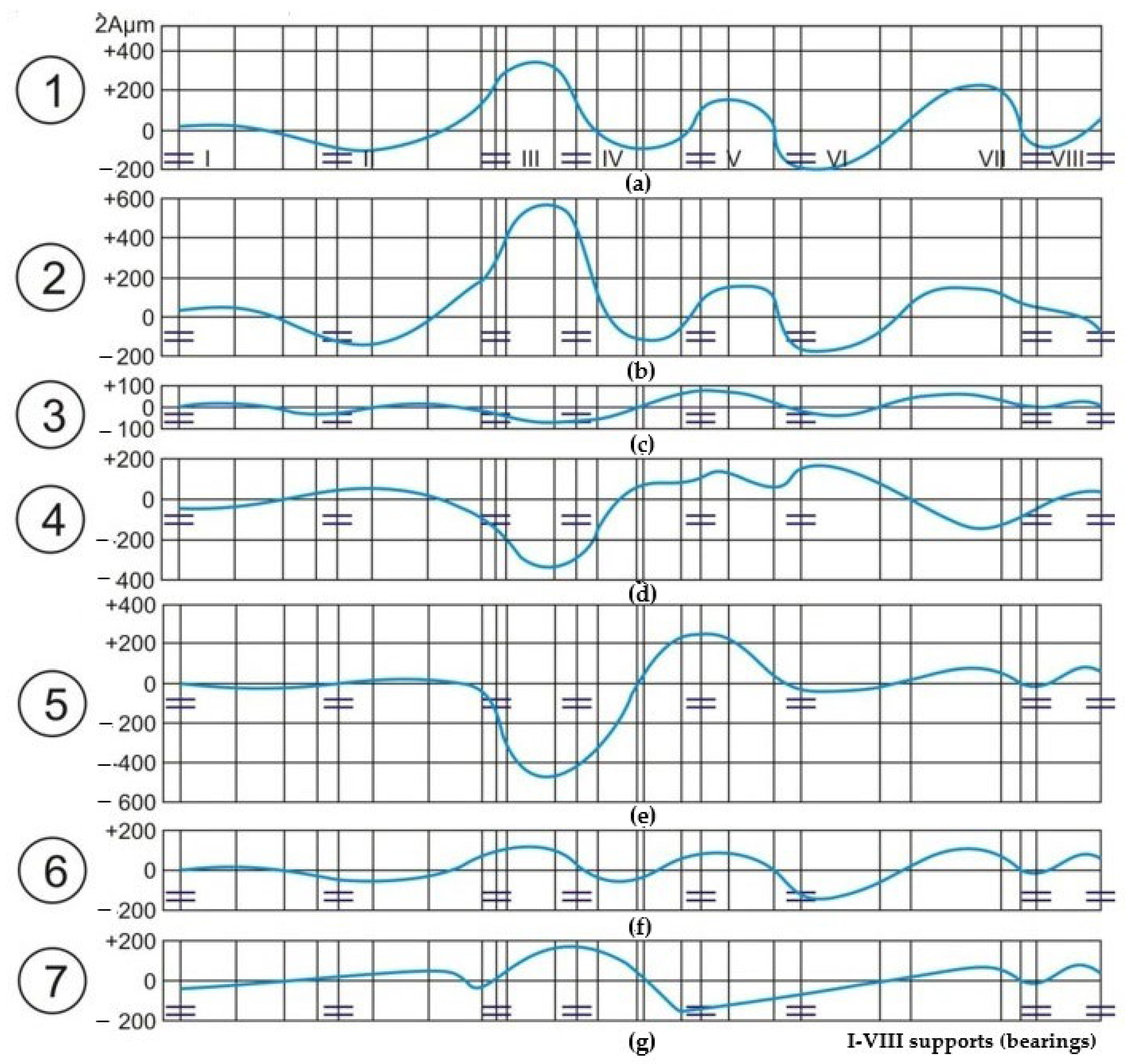
3.1. Vibrations of Turbo Generator TVF-100-2

In the realm of thermal power plant operations, the importance of precise vibration monitoring for turbo generators cannot be overstated. While most modern generators are equipped with online systems featuring sensors for continuous vibration monitoring, supplementary instruments are often utilized to cross-verify measurement results. In this investigation, the vibration diagnostics instruments used were the MI-CROLOG CMVA 65 and CMVA 60 from SKF. These instruments are adept at diagnosing a range of issues including rotor eccentricity, imbalance, bent shafts, misalignment (both parallel and angular), sleeve bearing problems (such as rubbing, clearance issues, and lubrication oil distribution), resonance phenomena, mechanical imperfections, rotor and bearing damage, pump problems (turbulence, cavitation), and electrical equipment issues (such as stator eccentricity and damage).
The layout of the turbo generator TVF-100-2, along with the measurement points and directions, is depicted in Figure 1. The figure shows the specific locations for the sliding bearings (N1 to N8), rigid couplings (S1 to S3), and pressure zones (C.N.V for low pressure and C.V.P for high pressure).
For the purpose of vibration monitoring, two types of sensors were utilized: absolute vibration sensors and relative vibration sensors. The absolute vibration sensors (depicted in Figure 1b) were mounted on the bearing housings and measured the vibrations of the entire support structure relative to a fixed reference (ground). The relative vibration sensors (depicted in Figure 1c) were installed to measure the displacement between the rotor shaft and the bearing housing, providing detailed information on rotor-specific dynamic behavior.
An approximate dimensional scale of the rotor components for the TVF-100-2 turbo generator is presented in Table 1.
To enhance the clarity and reproducibility of the experimental procedure, we have explicitly distinguished between general background information and the specific methodology applied in this study. The vibration measurements were conducted during full-load operation of the turbo generator at 100 MW, ensuring realistic assessment under nominal conditions. Sensors were mounted directly onto the bearing housings at predefined measurement points (N1–N8), as shown in Figure 1. Each measurement session lasted approximately 20 min and captured both transient and steady-state operating conditions. The testing protocol followed a sequential procedure that included baseline diagnostics, phase analysis for unbalance identification, trial weight application at specified rotor locations, and post-balancing verification measurements.
Measurements were conducted with a sampling frequency of 6.4 kHz, ensuring accurate capture of the relevant vibration spectrum. The accelerometers employed were ICP-type with a sensitivity of 100 mV/g, allowing for precise detection of both low- and high-frequency components. Prior to data acquisition, all equipment was calibrated in accordance with ISO 10816-3 standards [31] to ensure measurement reliability and consistency across test sessions.
This structured approach enabled targeted vibration mitigation based on empirical data and phase correlation techniques.

3.2. Impact of Load on Turbo Generator

Rotor imbalance significantly influences the operational stability and efficiency of turbomachinery in thermal power plants. This section presents experimental investigations into how different loading systems affect rotor vibrations, with a specific focus on the impact of both symmetrical and asymmetrical load distributions.
Figure 2 consists of seven subplots (labeled 1 to 7), each illustrating the vibration amplitude (Aμm) as a function of the rotor’s angular position. The x-axis represents the positions (I to VIII), corresponding to the bearings (supports), while the y-axis shows the vibration amplitude in micrometers.
These plots demonstrate that different configurations and placements of asymmetric loads can markedly affect the vibration characteristics of the rotor. Configurations involving shifts in the coupling tend to result in higher vibration amplitudes, indicating increased sensitivity. The effectiveness of the asymmetric load system is context-dependent, becoming more pronounced in specific balancing scenarios. This detailed visualization aids in comprehending the complex dynamics of rotor vibrations under various asymmetric loading conditions, crucial for optimizing rotor performance and minimizing vibrations in turbomachinery.
The use of an asymmetric loading system in the tangential plane of the low-pressure rotor (LPR) has been found to be less effective, showing its utility primarily during the balancing process (Figure 2c, curve 3). Conversely, placing asymmetric loads in the tangential plane of the generator rotor impacts the entire rotor system (Figure 2f, curve 6). Similarly to symmetrical systems, shifting one of the loads in asymmetric systems on the coupling seldom increases the rotor’s sensitivity (Figure 2b,d,e,g, curves 2, 4, 5, 7).
In Figure 2, phase shifts are implicitly reflected in the angular displacement of maximum vibration amplitudes at different bearings when asymmetric loads are applied. These variations illustrate changes in the dynamic response and phase relationship between the excitation force and vibration response at various positions along the rotor.
Additionally, the shifts in the vibration amplitude maxima across different bearings (positions I–VIII) indicate the presence of phase changes in the rotor response. These phase shifts are induced by the asymmetric loading and affect the angular position of maximum deflection along the rotor, highlighting the sensitivity of the system to load-induced dynamic variations.
In contrast, Figure 3 examines the vibration responses of different rotor components under symmetrical imbalance conditions.
The figure consists of four sub-diagrams, labeled with letters from (a) to (d), each depicting the vibration amplitude (Aμm) as a function of the rotor’s angular position. The x-axis represents the positions (I to VIII), corresponding to the bearings (supports), while the y-axis shows the vibration amplitude in micrometers.
  • Curve 1: The high-pressure rotor (HPR) displays relatively low vibration amplitudes across all angular positions, indicating good balance under symmetrical loading.
  • Curve 2: The medium-pressure rotor (MPR) exhibits slightly higher vibration amplitudes than the HPR, indicating moderate sensitivity to symmetrical imbalance.
  • Curve 3: The low-pressure rotor (LPR) demonstrates the highest vibration amplitudes among the three rotors, suggesting it is the most sensitive to symmetrical imbalance.
  • Curve 4: The generator rotor shows vibration amplitudes generally higher than those of the HPR and MPR, but lower than those of the LPR.
This figure underscores how symmetrical imbalance affects the vibration behavior of various components within the turbomachine. The LPR is particularly sensitive, resulting in higher vibration amplitudes. Understanding these characteristics is vital for improving rotor balance and reducing vibration levels in the turbomachinery system.
Figure 3 and Figure 4 show phase-related effects under symmetrical and asymmetrical imbalance distributions, respectively.
It is noteworthy that under symmetrical imbalance (Figure 3), the phase relationships between different rotor sections remain relatively uniform, resulting in coherent vibration behavior with minimal phase lag across the components. This consistent phase alignment contributes to lower overall vibration amplitudes compared to asymmetrical cases.
Asymmetrical imbalance has a more pronounced impact on rotor dynamics, particularly affecting the LPR and subsequently the generator rotor (Figure 4). The subplots illustrate the vibration responses of different rotor components under these conditions.
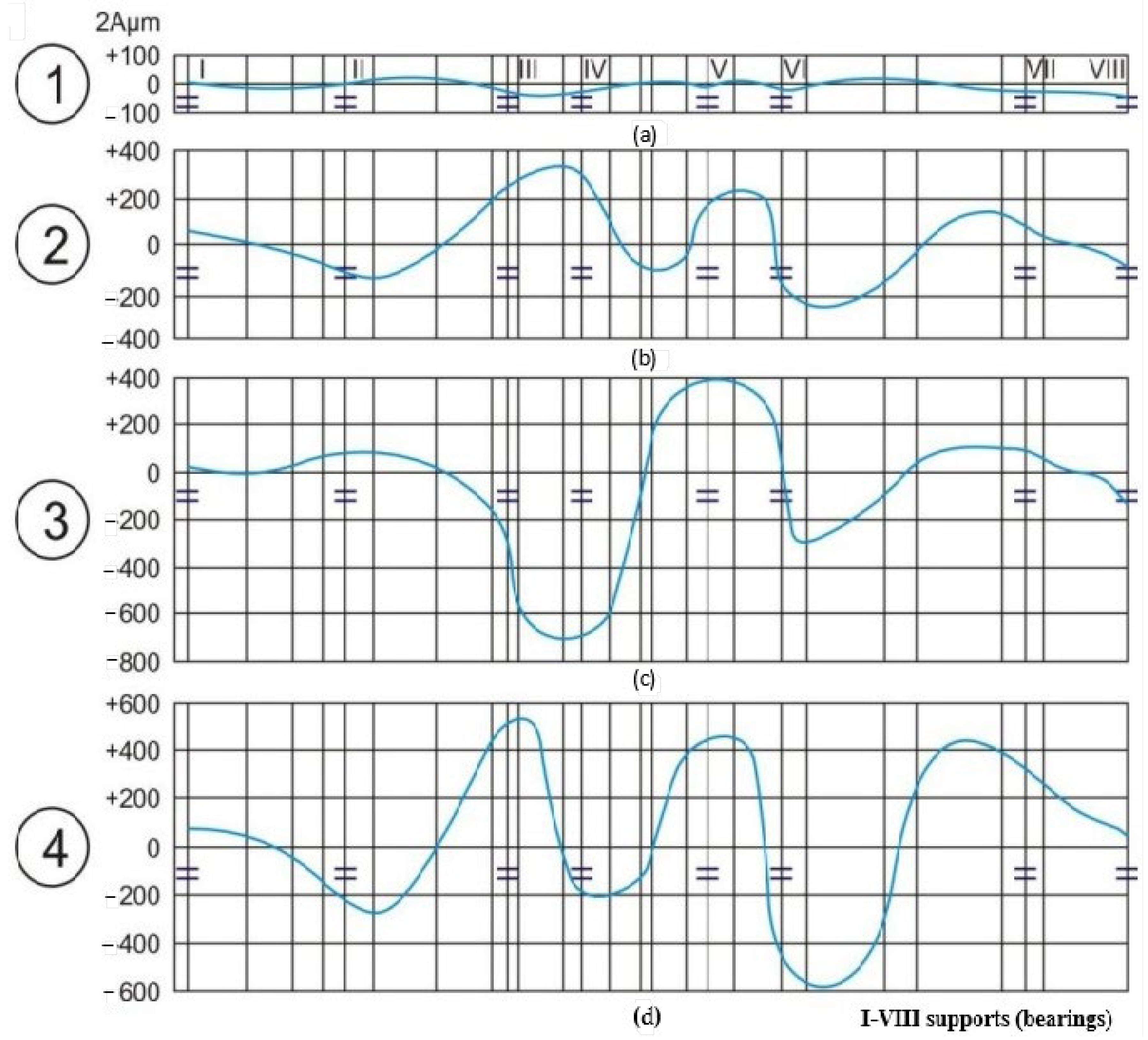
  • Curve 1: The HPR shows minimal vibration amplitudes, indicating it is less affected by asymmetrical imbalance.
  • Curve 2: The MPR exhibits moderate vibration amplitudes, showing moderate sensitivity.
  • Curve 3: The LPR has the highest vibration amplitudes, indicating high sensitivity to asymmetrical imbalance, which significantly impacts the generator rotor.
  • Curve 4: The generator rotor displays substantial vibration amplitudes, which are relatively uniform, indicating that the imbalance affects all parts of the rotor system evenly.
The asymmetrical imbalance illustrated in Figure 4 induces significant phase shifts among different rotor segments, particularly in the low-pressure rotor (LPR) and generator rotor. These phase variations lead to complex vibration patterns, where the angular positions of maximum amplitudes differ more markedly between supports, reflecting the destabilizing effect of asymmetrical unbalance on rotor dynamics.
In symmetrical cases (Figure 3), the phase difference across different rotor components is relatively small, while asymmetrical imbalance (Figure 4) introduces more pronounced phase shifts, especially in the low-pressure rotor (LPR) and generator rotor.
This analysis elucidates how different rotor components respond to asymmetrical imbalance, which is critical for improving the balancing process and reducing vibrations. The LPR’s heightened sensitivity to asymmetrical imbalance significantly affects the generator rotor, while the generator rotor’s imbalance uniformly impacts all rotor components. Notably, throughout these experiments, the LPR consistently exhibited higher sensitivity to imbalance. This heightened sensitivity is primarily due to the LPR’s structural flexibility, as it possesses a relatively lower stiffness and mass moment of inertia compared to other components in the rotor train. Furthermore, its geometric positioning—extending across a longer unsupported span between bearings and located closer to the generator coupling—renders it more susceptible to dynamic deflections.
Understanding these dynamics is essential for optimizing rotor performance and enhancing the overall stability of turbomachinery in thermal power plants.
All experimental vibration measurements presented in Figure 2, Figure 3 and Figure 4 were performed during the full-load operation of the turbo generator at 100 MW output and 3000 RPM rotational speed. The operating conditions corresponded to the standard nominal parameters of the TVF-100-2 unit, without external disturbances other than the controlled application of test loads for balancing analysis.

4. Results and Discussion

Balancing of the Turbo Generator
Balancing a turbo generator is a meticulous process that ensures operational stability and efficiency in the machinery. During this process, the vibrations of the support are frequently measured, including the relative vibrations of the rotor at various distances from the support. These measurements are complemented by data on rotor vibration in the plane of the support, which allows for precise balancing and accurate depiction of the rotor’s elastic lines before and after balancing.
The experimental data demonstrate that, prior to balancing, the rotor’s elastic lines exhibit significant deflection (curve 1 in Figure 5a). The ideal final shape of the elastic lines, which minimizes vibration, is achieved by applying two symmetrical loads on the couplings (curve 2 in Figure 5a). After a certain period of operation, the turbomachinery was halted to apply symmetrical loads of 0.90 kg each on the LPR couplings. This intervention significantly reduced the elastic deflection of the rotor (curve 3 in Figure 5a) and the inherent vibrations of the support.
Subsequent balancing trials concluded that an optimal load of 0.80 kg was necessary for final balancing (curves 4 and 5 in Figure 5a). Another case involved a different approach to shaping the rotor’s elastic lines, initially depicted by curve 1 in Figure 5b. The optimal shape was influenced by the load on the MPR-LPR coupling (curve 7 in Figure 5b). When the turbomachinery was started up with a pre-assembled load of 0.40 kg, the expected balance and vibration reduction were achieved.
The selected load magnitudes (0.90 kg, 0.80 kg, and 0.40 kg) were determined empirically, based on prior experience with similar rotor systems and their known sensitivity to unbalance within the analyzed operational range. These mass values were chosen to reflect realistic unbalance conditions that typically occur in practice and to allow for gradual adjustment of the dynamic response. The distribution and magnitude of the trial weights were further refined by evaluating the vibration response function during preliminary test runs, ensuring that the system’s reaction remained within a measurable and interpretable range without exceeding safe vibration limits.
The provided image, Figure 5, contains two sets of graphs related to the balancing of a turbo generator. These graphs illustrate imbalance measurements and adjustments over multiple stages (I to VIII) for the LPR, generator rotor (GR), and Low-Pressure Turbine (LPT). The lines in the graphs represent the paths of the rotor during the balancing process.
Upper Graph (Figure 5a): Imbalance of LPR and GR
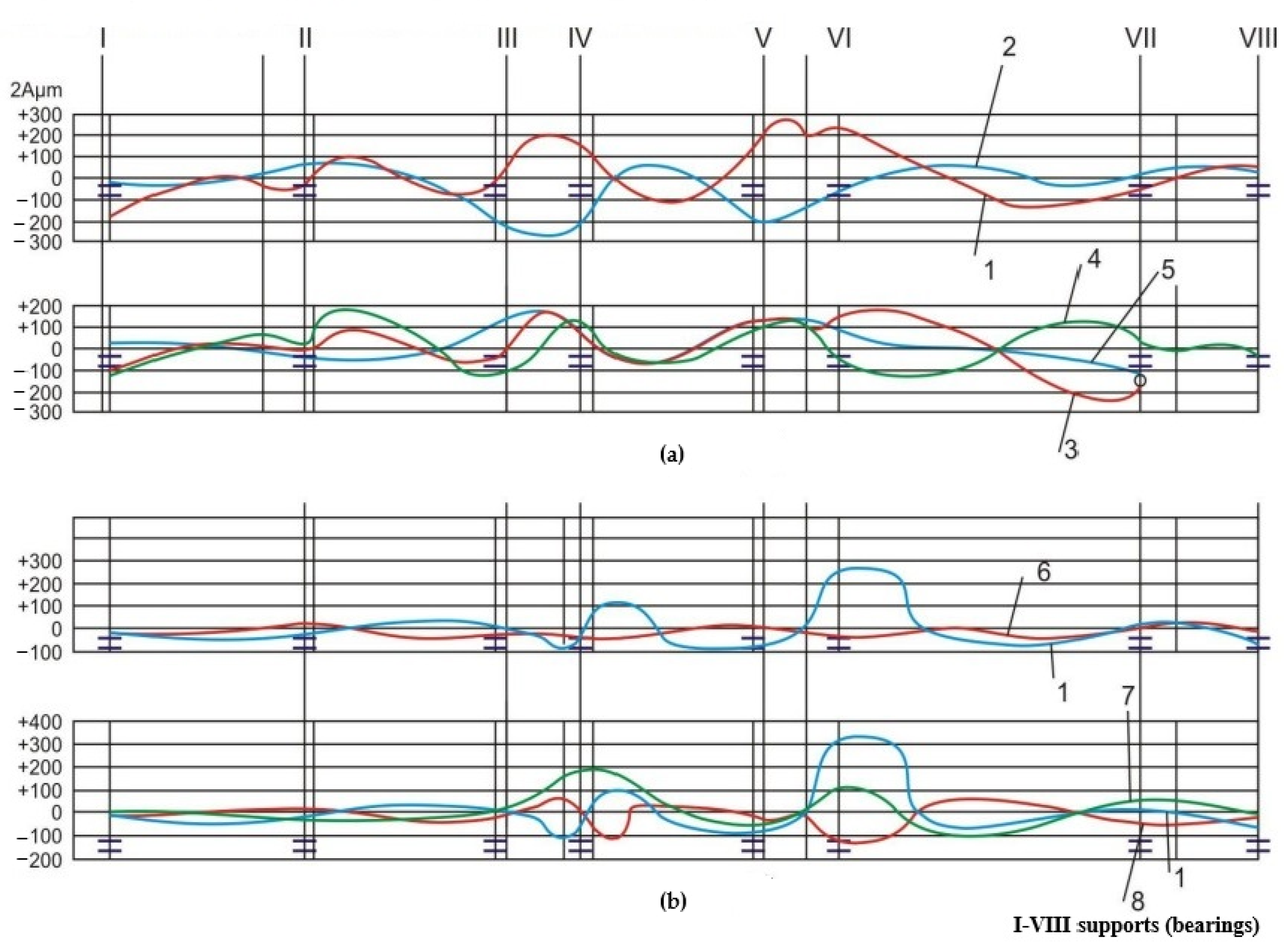
  • Line 1 (Red): This represents the initial imbalance of the LPR and GR, with amplitude variations ranging from +300 μm to −300 μm.
  • Line 2 (Blue): This depicts the adjustments made to counter the imbalance, with notable amplitude changes indicating major corrections.
  • Lines 3 (Red), 4 (Green), and 5 (Blue): These lines represent finer adjustments or specific measurement points, with lower amplitude ranges compared to lines 1 and 2, indicating more precise balancing adjustments.
Lower Graph (Figure 5b): Imbalance of LPT
  • Line 1 (Blue): This illustrates the initial imbalance of the LPT, with amplitude variations between +300 μm and −300 μm.
  • Line 7 (Green): This shows the corrective measures taken to balance the LPT, with significant adjustments similar to that in the LPR and GR adjustments.
  • Line 8 (Red): This represents another specific measurement or adjustment point with relatively minor amplitude variations, suggesting small corrections during the balancing process.
Stages I to VIII represent different load conditions or steps in the balancing process. Each stage corresponds to a different configuration or placement of loads used to move and balance the rotor. The significant changes in the graphs at certain stages highlight critical points where major balancing adjustments are necessary.
This detailed analysis of the balancing process for the turbo generator underscores the importance of a staged approach to achieve optimal balance. A comprehensive understanding of how imbalances and corrective actions fluctuate across different stages is crucial for ensuring the efficient and stable operation of the turbo generator. The ability to fine-tune adjustments through continuous monitoring and precise measurement is vital for maintaining the operational integrity and longevity of the turbomachinery.
The graph implicitly contains information about the phase shift in vibrations, which is reflected in changes to the rotor line shape depending on the position and mass of the balancing weights. The phase shift in vibrations is recognized through the displacement of the point of maximum amplitude along the phase positions, as well as through variations in the slope and symmetry of the deformation line observed across different loading configurations, for example, between Lines 1, 4, and 5. These changes indicate phase differences relative to the reference position of the rotor during rotation. In the context of experimental balancing, the analysis of vibration phase shifts plays a crucial role, as it enables the precise localization of the dominant imbalance and determination of the optimal angular placement of correction masses. Although the phase is not explicitly expressed in degrees on the presented graph, its influence is clearly demonstrated through the shape and behavior of the vibration lines, which vary according to the mass distribution within the system.
Based on the experimental measurements presented in Figure 5, the initial vibration amplitude of the LPR and the GR was recorded at approximately ±300 μm (Line 1), indicating significant unbalance and pronounced elastic deformation. Following the application of symmetrical trial weights of 0.90 kg, and subsequently optimized correction weights of 0.80 kg, the vibration amplitude was reduced to approximately ±100 μm (Lines 4 and 5). This represents a reduction of about 66% in amplitude, confirming the effectiveness of the applied balancing method.
Moreover, the results presented in this study provide a practical foundation for developing predictive maintenance strategies. By identifying characteristic vibration signatures associated with specific imbalance conditions and load configurations, maintenance teams can establish threshold values and early warning indicators. These indicators enable timely interventions before significant deterioration or damage occurs. Thus, the vibration-based insights obtained from the staged balancing process can be directly integrated into condition monitoring systems, facilitating proactive maintenance scheduling and reducing unplanned downtime.

5. Conclusions

The experimental investigations into rotor imbalance in a thermal power plant highlight the critical role of precise balancing in maintaining the operational efficiency and stability of turbomachinery. Through the implementation of both asymmetric and symmetrical loading systems, it has been observed that different configurations and placements of loads can significantly influence the vibration characteristics of various rotor components.
In the initial stages of balancing, the asymmetrical loading system showed effectiveness only during specific balancing scenarios, indicating its context-dependent nature. Symmetrical loading, on the other hand, demonstrated a more consistent influence on vibration reduction across different rotor components. The LPR was particularly sensitive to both symmetrical and asymmetrical imbalances, necessitating careful monitoring and adjustment.
Detailed analysis of the balancing process revealed that significant corrections were often required at specific stages, as indicated by the substantial adjustments observed in the graphs. For instance, in the case of the LPR and GR, the initial vibration amplitudes reached values of ±300 μm (Figure 5a, Line 1). After applying 0.90 kg symmetrical loads, the amplitudes were reduced to approximately ±150 μm (Figure 5a, Line 3), and further decreased to less than ±100 μm following the final 0.80 kg load adjustment (Figure 5a, Lines 4 and 5), corresponding to a total reduction of over 65%. Similarly, in the LPT balancing process, the application of a 0.40 kg pre-assembled load brought the amplitude down from ±300 μm to about ±120 μm (Figure 5b, Line 7), evidencing a significant quantitative improvement. The application of symmetrical loads to the couplings resulted in notable reductions in elastic deflection and inherent vibrations, demonstrating the effectiveness of these corrective measures.
Overall, the findings underscore the importance of a systematic and precise approach to balancing turbo generators. By meticulously monitoring and adjusting for imbalances, it is possible to optimize rotor performance, minimize vibrations, and ensure the reliable operation of turbomachinery in thermal power plants. This approach not only enhances the efficiency of the power plant but also extends the lifespan of the equipment, reducing maintenance costs and improving overall operational stability.

Author Contributions

Conceptualization, S.P. and M.V.; Methodology S.V. and S.P.; Software, D.B. and B.R.; Validation, J.T.; Investigation, M.V.; Resources, S.V.; Writing—original draft, S.V.; Writing—review and editing, M.V. and S.P.; Visualization, M.J. and U.S.; Supervision, S.P. and M.V.; Project administration, M.V. and S.V.; Funding acquisition, S.P., J.T., B.R., D.B., and U.S. All authors have read and agreed to the published version of the manuscript.

Funding

This research received no external funding.

Data Availability Statement

The data presented in this study are available on request from the corresponding author.

Conflicts of Interest

The authors declare no conflicts of interest.

References

  1. Sun, N.Q.; Zhao, Z.J.; Zhang, Q.H.; Han, S.L.; Chen, X.X. Fault feature extraction of bearings for the petrochemical industry and diagnosis based on high-value dimensionless features. Trans. Famena 2022, 46, 31–44. [Google Scholar] [CrossRef]
  2. Sun, L.; Zhang, Q.; Liu, G.; Sun, N.; Yang, P. A dimensionless immune intelligent fault diagnosis system for rotating machinery. Trans. Famena 2022, 46, 23–36. [Google Scholar] [CrossRef]
  3. Adamović, Z.; Josimović, L.; Vulović, S.; Ilić, B.; Spasić, D. Vibro-Diagnostic Maintenance of Technical Systems; Serbian Society for Technical Diagnostics: Belgrade, Serbia, 2016. [Google Scholar]
  4. Shengyuan, L.; Longxi, Z. Vibration attenuation mechanism of the rotor system with anisotropic support stiffness. Trans. Famena 2021, 45, 129–144. [Google Scholar] [CrossRef]
  5. Adel, A.S.; Emad, A.N.; Hisham, A.M.; Abdulrahman, A.A.; Ali, K.K.; Husam, K.; Haitham, A.; Mahmoud, A. New association analysis-based method for enhancing maintenance and repair in manufacturing. Trans. Famena 2021, 45, 85–104. [Google Scholar] [CrossRef]
  6. Prvulović, S.; Tolmač, D.; Dimitrijević, D.; Tolmač, J. Research of sensibility and tendency rotors to unbalance. J. Balkan Tribol. Assoc. 2012, 18, 365–380. [Google Scholar]
  7. Vulović, S.; Spasić, D.; Vulović, M.; Radovanović, L.; Otić, G. Vibrodiagnostic automated system. In Proceedings of the 25th International Conference on Noise and Vibration, University of Niš, Tara, Serbia, 26–28 October 2016. [Google Scholar]
  8. El-Mongy, H.H.; Younes, Y.K. Vibration analysis of a multi-fault transient rotor passing through sub-critical resonances. J. Vib. Control 2018, 24, 2986–3009. [Google Scholar] [CrossRef]
  9. Vulović, S. Integrated Maintenance Model Based on the Change of Vibrations in Rotating Technical Systems. Ph.D. Thesis, University of Novi Sad, Novi Sad, Serbia, 2017. [Google Scholar]
  10. Tiboni, M.; Remino, C.; Bussola, R.; Amici, C. A Review on Vibration-Based Condition Monitoring of Rotating Machinery. Appl. Sci. 2022, 12, 972. [Google Scholar] [CrossRef]
  11. Davila-Alfaro, G.d.J.; Salas-Reyes, A.E.; Chaires, J.M.; Arcos-Gutiérrez, H.; Garduño, I.E.; Gallegos-Melgar, A.; Hernández-Hernández, M.; Mercado-Lemus, V.H. The Study of the Balancing Process for Starting Rotors in Heavy-Duty Vehicles: An Industrial Application. Vehicles 2024, 6, 1752–1768. [Google Scholar] [CrossRef]
  12. Zhou, S.; Shi, J. Active balancing and vibration control of rotating machinery: A survey. Shock and Vibration Digest. 2001, 33, 361–371. [Google Scholar] [CrossRef]
  13. Meslameni, W.; Kamoun, T. Detection of an Imbalance Fault by Vibration Monitoring: Case of a Screw Compressor. J. Appl. Res. Ind. Eng. 2021, 8, 27–39. [Google Scholar] [CrossRef]
  14. Hundal, M. Trial-weight-free dynamic balancing method based on modal parameters. J. Sound Vib. 1981, 77, 29–42. [Google Scholar]
  15. Morton, P.G. Modal balancing of flexible shafts without trial weights. Proc. Inst. Mech. Eng. Part C J. Mech. Eng. Sci. 1985, 199, 71–78. [Google Scholar] [CrossRef]
  16. Delgado, E.P.; Bannister, R.H. Balancing of an Experimental Rotor without Trial Runs. Int. J. Rotating Mach. 2002, 8, 99–108. [Google Scholar] [CrossRef]
  17. Khulief, Y.A.; Mohiuddin, M.A.; El-Gebeily, M. A new method for field-balancing of high-speed flexible rotors without trial weights. Int. J. Rotating Mach. 2014, 603241. [Google Scholar] [CrossRef]
  18. Parkinson, A. A review of rotating machinery. J. Sound Vib. 1991, 150, 289–300. [Google Scholar]
  19. Foiles, W.C.; Allaire, P.E.; Gunter, E.J. Review: Rotor balancing. Shock Vib. 1998, 5, 325–336. [Google Scholar] [CrossRef]
  20. Zhou, S. Dynamic modeling and analysis techniques for rotating machinery. Mech. Syst. Signal Process. 2002, 16, 599–616. [Google Scholar] [CrossRef]
  21. Saldarriaga, M.V.; Mahfoud, J.; Steffen Jr., V.; Der Hagopian, J. Adaptive balancing of highly flexible rotors by using artificial neural networks. Smart Struct. Syst. 2009, 5, 507–515. [Google Scholar] [CrossRef]
  22. Chatzisavvas, I.; Dohnal, F. Unbalance identification using the least angle regression technique. Mech. Syst. Signal Process 2015, 50–51, 706–717. [Google Scholar] [CrossRef]
  23. Ibn Shamsah, S.M.; Sinha, J.K. Rotor unbalance estimation with reduced number of sensors. Machines 2016, 4, 19. [Google Scholar] [CrossRef]
  24. Zou, D.; Zhao, H.; Liu, G.; Ta, N.; Rao, Z. Application of augmented Kalman filter to identify unbalance load of rotor-bearing system: Theory and experiment. J. Sound Vib. 2019, 463, 114972. [Google Scholar] [CrossRef]
  25. Zhao, Y.; Wang, H.; Sun, Z. Balancing method based on transient characteristics and dynamic load identification. Mech. Syst. Signal Process. 2015, 64–65, 52–64. [Google Scholar] [CrossRef]
  26. Wang, X.; Yu, L.; Zhang, Y. Algorithms for Unbalance Identification in Multi-Disc and Multi-Span Rotors. J. Sound Vib. 2018, 422, 147–161. [Google Scholar] [CrossRef]
  27. Bachschmid, N.; Pennacchi, P.; Tanzi, E. Model-Based Fault Identification in Rotating Machinery. Mech. Syst. Signal Process. 2012, 29, 214–230. [Google Scholar] [CrossRef]
  28. Ya, J.; Tang, H.; Liang, Y. Modal Expansion and Optimization Algorithms for Rotor Unbalance Fault Identification. Mech. Syst. Signal Process. 2014, 46, 285–300. [Google Scholar] [CrossRef]
  29. Shrivastava, R.; Gupta, A. Unbalance Fault Identification Using Kalman Filter and Recursive Least Squares. J. Vib. Acoust. 2010, 132, 041010. [Google Scholar] [CrossRef]
  30. Sudhakar, M.; Raman, S. Improved Equivalent Load and Vibration Minimization Methods for Rotor Unbalance Identification. J. Sound Vib. 2019, 450, 161–173. [Google Scholar] [CrossRef]
  31. ISO 10816-3; Mechanical vibration—Evaluation of machine vibration by measurements on non-rotating parts—Part 3: Industrial machines with nominal power above 15 kW and nominal speeds between 120 r/min and 15,000 r/min when measured in situ. International Organization for Standardization: Geneva, Switzerland, 2009.
Figure 1. Layout and numeration of measurement locations for the turbo generator TVF-100-2: (a) General arrangement showing sliding bearings (N1–N8), rigid couplings (S1–S3), and pressure sections (C.N.V., C.V.P.). (b) Installation position of absolute vibration sensors mounted on bearing housings (vibrations measured relative to the ground). (c) Installation position of relative vibration sensors measuring shaft displacement relative to the bearing housings.
Symmetry 17 00743 g001
Figure 2. Influence of side-symmetrical loads on turbomachine vibrations at 3000 rpm (turbo generator TVF-100-2). (a) Curve 1—Reference configuration without additional lateral loads. (b) Curve 2—Asymmetrical load applied at the coupling with displacement. (c) Curve 3—Asymmetrical load applied in the tangential plane of the low-pressure rotor (LPR). (d) Curve 4—Alternative configuration of asymmetrical loading with a shifted element at the coupling. (e) Curve 5—Another case of shifting one load from a pair; behavior similar to that in curves 2 and 4. (f) Curve 6—Asymmetrical load applied in the tangential plane of the generator rotor. (g) Curve 7—Variation in the asymmetrical loading system with weak-to-moderate influence, without a notable increase in sensitivity.
Symmetry 17 00743 g002
Figure 3. The impact of symmetrical imbalance distribution on the vibration of the turbomachinery system at 3000 RPM (1–4: imbalance of HPR, MPR, LPR turbine rotors, and generator rotor; I–VIII: bearing supports). (a) Curve 1: The high-pressure rotor (HPR). (b) Curve 2: The medium-pressure rotor (MPR). (c) Curve 3: The low-pressure rotor (LPR). (d) Curve 4: The generator.
Symmetry 17 00743 g003
Figure 4. The impact of asymmetrical imbalance distribution on the vibration of the turbomachinery system at 3000 RPM (1–4: imbalance of HPR, MPR, LPR turbine rotors, and generator rotor; I–VIII: bearing supports). (a) Curve 1: Imbalance of HPR turbine rotors. (b) Curve 2: Imbalance of MPR turbine rotors. (c) Curve 3: Imbalance of LPR turbine rotors. (d) Curve 4: Imbalance of generator rotor.
Symmetry 17 00743 g004
Figure 5. Balancing of a turbo generator: (a) imbalance of LPR and generator rotor (GR); (b) imbalance of LPT; (I-VIII loads placed on a device for moving a rotor; 1–8 lines of a rotor in the process of balancing).
Symmetry 17 00743 g005
Table 1. Approximate dimensional scale of the rotor.
ComponentEstimated LengthEstimated DiameterRemarks
High-pressure rotor (HPR)~1.5 m~0.4–0.5 mCompact geometry due to higher temperatures and smaller blades.
Medium-pressure
rotor (MPR)
~1.5–2 m~0.6 mLarger blade diameters and increased length.
Low-pressure rotor (LPR)~2.5–3 m~0.8–1.2 mLargest rotor, often featuring a double-flow configuration.
Generator rotor~1.5–2 m~0.5–0.6 mCylindrical geometry with evenly distributed loading.
Note: The listed dimensions represent approximate ranges observed along different sections of each rotor component, reflecting variations in shaft diameter and geometry at blade regions, coupling zones, and intermediate segments.
Disclaimer/Publisher’s Note: The statements, opinions and data contained in all publications are solely those of the individual author(s) and contributor(s) and not of MDPI and/or the editor(s). MDPI and/or the editor(s) disclaim responsibility for any injury to people or property resulting from any ideas, methods, instructions or products referred to in the content.

