Article

PMSM Speed Control Based on Improved Adaptive Fractional-Order Sliding Mode Control

1
Ruidian Technology Co., Ltd., Beijing 100068, China
2
Department of Electronics Engineering, National Taipei University of Technology, Taipei 160344, Taiwan
*
Author to whom correspondence should be addressed.
Symmetry 2025, 17(5), 736; https://doi.org/10.3390/sym17050736
Submission received: 19 March 2025 / Revised: 27 April 2025 / Accepted: 8 May 2025 / Published: 10 May 2025
(This article belongs to the Special Issue Symmetry/Asymmetry in Intelligent Control Systems)

Abstract

:
Addressing the problem of poor robustness and anti-interference ability in the permanent magnet synchronous motor (PMSM) speed control system, an adaptive fractional-order sliding mode controller based on a fractional-order sliding mode disturbance observer is proposed. Firstly, a mathematical model of a PMSM is established, which combines adaptive control with fractional order sliding mode control to effectively reduce the drawbacks of traditional integer order sliding mode control and improve the control accuracy of the system. At the same time, a new sliding mode approach law is used to replace the traditional exponential approach law, which reduces system buffeting and improves control performance. We use a fractional-order sliding mode observer to observe external disturbances and perform feedforward compensation on the observed disturbance values to improve the system’s anti-interference ability. By combining adaptive control with fractional-order sliding mode techniques, the system mitigates limitations of traditional integer-order approaches. It enhances symmetry preservation in system response and control accuracy under asymmetric conditions. The simulation results show that the motor system using the improved sliding mode disturbance observer and fractional order sliding mode controller can enhance system stability and anti-interference ability, and has better dynamic and steady-state performance.

1. Introduction

PMSMs have become pivotal in modern electromechanical applications, owing to their outstanding control precision, compact structure, and high energy conversion efficiency. In recent years, PMSMs have been widely adopted in diverse sectors, including renewable energy systems, aerospace, advanced manufacturing, and automated machinery [1,2,3,4,5,6,7,8]. Despite these advantages, the speed control of the PMSM remains technically demanding due to its inherent nonlinearities, strong coupling effects, and multivariable dynamics. Such characteristics make PMSM systems particularly susceptible to performance degradation when faced with internal parameter variations, such as magnetic saturation or external disturbances; for example, abrupt changes in load torque. As a result, achieving accurate and robust speed regulation over a wide range of operating conditions continues to pose a significant challenge. Conventional control strategies often struggle to maintain optimal performance under these complex and variable circumstances [9,10,11,12,13,14,15,16,17].
To address the aforementioned challenges in PMSM speed regulation, a variety of advanced control methodologies have been explored in recent years. These include sliding mode control (SMC), active disturbance rejection control (ADRC), robust and adaptive control schemes, as well as intelligent approaches based on fuzzy logic and neural networks [18,19,20,21,22,23,24,25]. The primary objective of these methods is to enhance system robustness and maintain precise control performance under complex and dynamic operating conditions. Among these strategies, SMC has attracted significant attention for servo applications due to its fast transient response and inherent robustness against parameter variations. However, a major limitation of conventional SMC remains the chattering phenomenon, which continues to hamper control precision and can introduce undesirable mechanical effects in practical implementations [26,27,28,29,30,31].
Recent advancements in SMC methodologies have shown promising results. For instance, Zheng et al. developed a decoupled super-twisting algorithm SMC (STA-SMC) framework that incorporates adaptive parameter estimation for PMSM drives. This method effectively integrates extended Kalman filtering (EKF) with binary polynomial approximation to dynamically compensate for variations in electromechanical parameters. Experimental results demonstrated a 34.5% improvement in torque ripple suppression and a 22.8% reduction in settling time compared to conventional SMC implementations [32]. However, in practical scenarios, the slip mode gain of STA-SMC requires knowledge of the upper bound of the perturbation derivative, which is often difficult to determine and increases the challenge of parameter design [33]. To overcome this issue, Chen et al. proposed a self-triggered super-twisting algorithm (ST-STA) for PMSM speed regulation. This approach utilizes a modified particle swarm optimization (PSO) algorithm incorporating Lévy flight characteristics, enabling automated gain optimization and achieving 78.6% faster convergence than standard PSO. The optimized STA yields a 62.3% reduction in chattering amplitude while maintaining a reaching time within 0.15 s [34]. Nevertheless, these advanced algorithms still depend on conventional linear sliding mode surfaces, which limit further improvements in robustness and convergence speed.
Fractional order sliding mode control (FOSMC) offers an effective solution to the aforementioned problems. By introducing a fractional-order sliding surface, FOSMC attenuates high-frequency oscillations through gradual energy dissipation during phase trajectory switching, thereby effectively suppressing control chattering. Additionally, the fractional-order sliding surface often preserves certain symmetries in the error dynamics, which enhances overall system stability and ensures more symmetric convergence to the sliding manifold compared to integer-order controllers [35]. Recent developments in this field mainly follow two technical pathways. In the observer-based approach, Zhang et al. proposed a compound estimation framework for PMSM speed servo systems by integrating an enhanced disturbance observer (DO) with a nonlinear extended state observer (NESO) to simultaneously track exogenous disturbances and parameter uncertainties [36]. Their method, which combines fractional-order switching laws with disturbance feedforward compensation, achieved a 39.7% reduction in speed overshoot and a 58.2% improvement in settling time compared to conventional SMC in experimental tests. From a sliding surface design perspective, Wang and Li introduced a dual fractional-integral sliding surface architecture that enhances traditional integral SMC through three innovations: (1) employing Riemann–Liouville fractional operators for improved dynamic response; (2) incorporating super-twisting reaching laws with sigmoid modulation; and (3) applying gradient descent for automatic parameter tuning [37]. Simulation results showed a 67.3% reduction in chattering amplitude and a maintained response time of 0.22 s under a 50% load torque variation. Fractional-order sliding mode observers are also designed to estimate and compensate for asymmetric external disturbances, thereby restoring system symmetry under varying loads. Furthermore, the introduction of fractional-order terms allows controlled asymmetry in the reaching phase, enabling faster convergence for large errors and reduced chattering as the sliding surface is approached. Consequently, FOSMC handles asymmetric uncertainties and disturbances more effectively than traditional integer-order controllers. By combining symmetric sliding surface design with asymmetric adaptive mechanisms, FOSMC achieves a well-balanced trade-off among stability, performance, and robustness, making it particularly suitable for controlling systems such as PMSMs, which exhibit both symmetric ideal behavior and asymmetric disturbances in real-world applications [38,39].
Despite these benefits, most existing FOSMC strategies do not comprehensively consider the influence of the reaching law on both chattering suppression and overall system performance. Motivated by these gaps, this paper proposes a novel adaptive fractional-order sliding mode control (AFOSMC) framework with integrated disturbance compensation for PMSM drives, introducing the following three core innovations:
(1)
Fractional-Order Disturbance Observer (FOSMDO): merges fractional calculus and sliding mode estimation for fast, accurate disturbance tracking, particularly against periodic load torques;
(2)
Adaptive Variable Exponential Reaching Law: employs a novel adaptive approach to reduce chattering and accelerate sliding mode convergence;
(3)
Integrated Fractional-Order Sliding Mode Observer: utilizes the estimated disturbance to compensate the q-axis current, further enhancing the system’s anti-disturbance capability.
The proposed approach is validated through comprehensive simulation studies, demonstrating significantly improved performance, including faster settling time, negligible overshoot, enhanced disturbance rejection, and resilience to parameter changes, over both conventional SMC and classical PI-controlled systems.
The remainder of this paper is arranged as follows. In Section 2, we analyze the mathematical model of PMSM. Section 3 details the proposed fractional-order sliding mode speed controller. Moreover, we present a new adaptive approach law based on the traditional exponential approach law to reduce controller chattering and enhance system dynamic performance. The fractional-order sliding mode observer for observing the system disturbances and improving the controller’s anti-interference ability is presented in Section 4. Simulation results and comparative analysis are discussed in Section 5. Finally, concluding remarks and future works are drawn in Section 6.

2. PMSM Mathematical Model

To establish a tractable control-oriented model, we adopt the following standard assumptions for PMSM modeling:
(1)
Three-phase symmetrical stator winding distribution with ideal electromagnetic characteristics;
(2)
Neglect of magnetic saturation effects and iron core losses;
(3)
Insensitivity of permanent magnet flux linkage (ψf) to temperature variations;
(4)
Exclusion of high-frequency parasitic effects and eddy current losses.
Under these idealized conditions, the electromagnetic dynamics can be effectively decoupled through coordinate transformation techniques. Following the Clarke transformation for phase variable conversion and the Park transformation for rotational frame alignment, the PMSM mathematical model in the stationary α-β reference frame is derived in axis-invariant form. The stator voltage equations are expressed as
L s (   d i α d t ) = R s i α e α + u α L s (   d i β d t ) = R s i β e β + u β
The mathematical model of the PMSM in the d-q coordinate system is
L s (   d i d d t ) = R s i d + ω e L s i q + u d L s (   d i q d t ) = R s i q ω e ( L s i d + ψ f ) + u q
The electromagnetic torque equation is
T e = 3 2 p i q ( i d ( L d L q ) + ψ f )
When the PMSM is a surface mount type, the inductance of the d-q axis is the same. The electromagnetic torque expression can be simplified to
T e = 3 2 p i q ψ f
The PMSM mechanical motion rotation equation is
J d ω r d t = T e T L B ω
The electromagnetic variables in the α-β stationary reference frame are defined as follows:
  • iα, iβ: Stator current components in α-β frame
  • uα, uβ: Stator voltage components in α-β frame
  • id, iq: Stator current components in d-q frame
  • ud, uq: Stator voltage components in d-q frame
  • eα, eβ: Back-EMF components
  • Rs: Stator resistance (Ω)
  • Ls: Stator winding inductance (H)
  • ψf: Permanent magnet flux linkage (Wb)
  • p: polar number
  • ωr: mechanical angular velocity (rad/s)
  • ωe: electrical angular velocity (rad/s)
  • Te: electromagnetic torque (N·m)
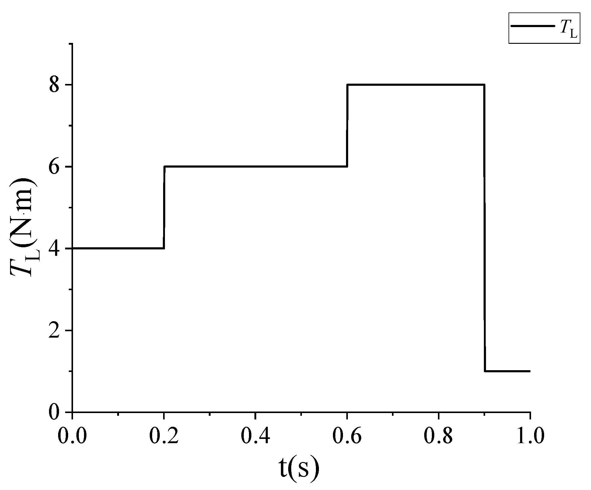
  • TL: load torque (N·m)
  • J: Moment of inertia (kg·m2)

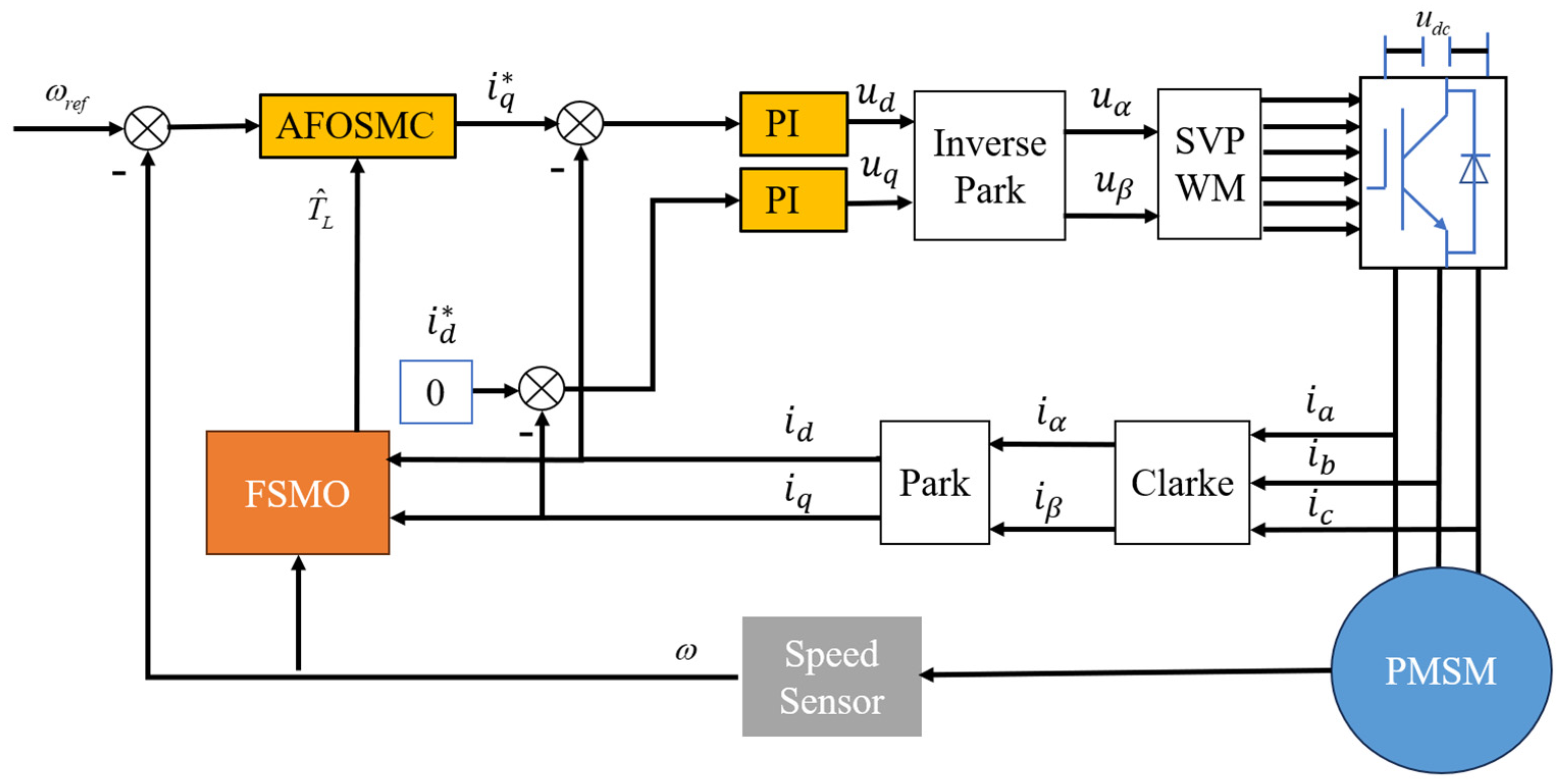
3. Design of Speed Controller

3.1. Fractional Order Controller Theory

As an extension of classical calculus, fractional calculus theory has demonstrated significant potential in modern engineering applications, particularly in developing advanced control systems with enhanced robustness. Fractional-order control methodologies, leveraging non-integer differentiation/integration operators, have emerged as a prominent research direction for addressing complex dynamic behaviors. The fractional calculus operator D f α e can be defined as
D f α e = d α d f α , R ( α ) > 0 1 , R ( α ) = 0 0 f ( d τ ) ( α ) , R ( α ) < 0
where e, f are the upper and lower bounds of the integral, α is the fractional order, and R ( α ) is the real part of α. For convenience, we use D α to replace D f α e .
Fractional calculus has undergone substantial theoretical development since its foundational mathematical formulations in the 19th century, with modern engineering applications emerging prominently in the 1980s. Three principal definitions govern fractional-order operations: the Grünwald–Letnikov (GL) formulation, the Riemann–Liouville (RL) definition, and the Caputo interpretation. The Caputo fractional derivative has gained predominant adoption in engineering practice due to its inherent advantage in handling conventional initial value conditions. Unlike the GL and RL definitions that involve fractional-order initial states (which lack direct physical interpretability), the Caputo operator maintains consistency with integer-order differential equations when describing dynamical systems with measurable initial conditions. The Caputo fractional derivative of order α ∈ (n − 1, n) for a function f(t) is formally defined as follows [40]:
t 0 D t α f ( t n ) = 1 Γ ( n α ) d n d t n t 0 t f ( τ ) ( t τ ) 1 + α n d τ
where n 1 α n and Γ ( . ) is Euler’s Gamma function.

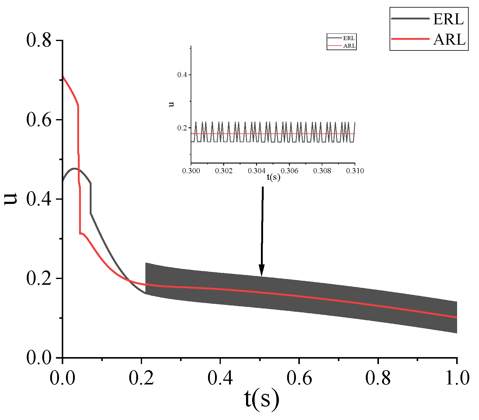
3.2. Design of a New Adaptive Approach Law

Building upon the pioneering theoretical framework established by Gao et al. [41], the sliding mode reaching law methodology has become fundamental in modern variable structure control systems. The conventional exponential reaching law (ERL), serving as the basis for advanced reaching law designs, is mathematically formulated as
s ˙ = ε s i g n ( s ) k s
Among them, ɛ > 0 and k > 0 are the sliding mode gain coefficients, s is the sliding mode surface, and when s approaches zero, its limit expression is
lim s 0 s ˙ = ε , s 0 + ε ,       s 0
The operational characteristics of the conventional exponential reaching law (ERL) can be analyzed through Equations (8) and (9). The system exhibits dual-phase convergence behavior. When the system state deviates significantly from the sliding manifold s, the trajectory converges with an exponential rate ks, ensuring rapid transient response. When the system approaches s, it approaches at a constant speed. Selecting the appropriate sum of k and ɛ is necessary to ensure that the system jitter is reduced while the approximation speed is accelerated, and the dynamic quality of the system is improved.
To address the inherent chattering phenomenon in conventional SMC while enhancing transient performance and steady-state accuracy, this work develops an adaptive reaching law (ARL) through two principal innovations:
S = s ˙ = ε ( t ) tanh ( s ϕ ) k ( t ) s μ sgn ( s ) k 1 s α E n sgn ( s )
where ε ( t ) and k ( t ) are the time-varying adaptive gain functions, sgn ( s ) is the sign function, k 1 > 0 , and 0 < α < 1 . Note that
(1)
The power term (0 < μ < 1) in s μ enhances the approach force when moving away.
(2)
The term E represents the Euclidean distance in the state space between the equilibrium point and the current position.
E = x 1 2 + x 2 2 + x 3 2 + x n 2
(3)
Switching Gain Adaptation Law ε ( t )
ε ˙ ( t ) = η 1 s t a n h ( s δ )
where η 1 > 0 is the adjustment rate and δ > 0 is to prevent high-frequency buffeting.
(4)
Power gain adaptation law k ( t ) :
k ( t ) = ξ + η 2 0 t s ( τ ) 1 + μ d τ
where the basic gain is ξ > 0, and the integration coefficient is η 2 > 0.
According to Lyapunov stability analysis, the Lyapunov function is selected as
V ( s ) = 1 2 s 2 + 1 2 η 1 ( ε ε * ) 2 + 1 2 η 2 ( k k * ) 2
By taking the derivative of Equation (14), we can obtain
V ˙ ( s ) = s ( ε ( t ) tan ( s ϕ ) k ( t ) s μ s i g n ( s ) k 1 s α E n s i g n ( s ) ) + 1 η 1 ( ε ε * ) ε ˙ + 1 η 2 ( k k * ) k ˙ = ε ( t ) s tan ( s ϕ ) k ( t ) s μ + 1 k 1 s α + 1 E n + 1 η 1 ( ε ε * ) η 1 s tanh ( s δ ) + 1 η 2 ( k k * ) η 2 s 1 + μ = ε ( t ) s tan ( s ϕ ) k 1 s α + 1 E n + ( ε ε * ) s tanh ( s δ ) k * s 1 + μ = ( k 1 s α + 1 E n ) + ( k * s 1 + μ ) + ( ε ( t ) s tan ( s ϕ ) + ( ε ε * ) s tanh ( s δ ) )
The above equation is divided into three parts to analyze the results:
Since k1 > 0, it leads to
k 1 s α + 1 E n < 0
Since k* is the upper bound of the ideal gain and k* > 0, we have
k * s 1 + μ < 0
Assuming the parameters are satisfied:
δ ϕ
It yields
t a n h ( s δ ) t a n h ( s ϕ )
Therefore, the third part in Equation (15) can be bounded as follows:
ε ( t ) s tan ( s ϕ ) + ( ε ε * ) s tanh ( s δ ) = s ( ε ( t ) tan ( s ϕ ) + ( ε ε * ) tanh ( s δ ) ) = s ( ε ( t ) ( tan ( s ϕ ) + tanh ( s δ ) ) ε * tanh ( s δ ) ) ε * tanh ( s δ ) 0
According to the above analysis and Lyapunov stability theorem, we have
V ˙ 0
Therefore, the system is stable, and the controller is designed to meet the stability requirements.
The second-order classical nonlinear control system is adopted as follows:
θ ¨ ( t ) = f ( θ , t ) + d ( t ) + b u ( t )
In Equation (22), θ(t) is the position function, u(t) is the control input, f(θ,t) is a known nonlinear function, and d(t) is an external disturbance. The unknown parameter b is not equal to 0. The goal of the control system is to design a controller u(t) that enables the system state signal θ(t) to track the desired signal θd(t).
Let the nonlinear function f(x(t),u(t)) be as follows:
x = x 1 x 2 T
x 1 = e = θ d θ x 2 = x ˙ 1 = e ˙ = θ ˙ d θ ˙
where x denotes the system state variable, x1 is defined as the tracking error difference, and x2 is the derivative of the tracking error.
Suppose the second-order nonlinear function is
f ( θ , t ) = a θ ˙
To suppress chattering, the sliding surface s is designed using an integral sliding surface as follows:
s = c e + e ˙
where c is greater than 0.
Among them, θd(t) is the ideal expected signal and can be expressed as follows:
θ d = cos ( t )
The sliding mode convergence law S is the derivative of the sliding mode surface s, that is
S = s ˙ = c e ˙ + e ¨ = c ( θ ˙ d θ ˙ ) + ( θ ¨ d ( a θ ˙ + d ( t ) + b u ( t ) ) )
According to Equation (22), the sliding mode controller u(t) is
u ( t ) = c ( θ ˙ d θ ˙ ) + θ ¨ d a θ ˙ d ( t ) S b
By introducing a new adaptive reaching law expression S, the controller expression can be obtained as follows:
u ( t ) = c ( θ ˙ d θ ˙ ) + θ ¨ d a θ ˙ d ( t ) ( ε ( t ) sgn ( s ) k ( t ) s μ sgn ( s ) k 1 s α E n sgn ( s ) ) b
Let a = 5, b = 1, c = 15, and the bounded disturbance d(t) be 2. The simulation parameters of ERL and ARL are shown in Table 1, and the simulation results of the two convergence laws are shown in Figure 1 and Figure 2. Figure 1 shows the variation of error e over time under two different convergence laws. Figure 2 shows the variation of controller u over time under two different convergence laws.
From the above results, compared to traditional ERL control, AVERL has good advantages in approaching speed and suppressing chattering. It converges quickly in approaching motion, improving system control accuracy.

3.3. Design of Fractional Sliding Mode Speed Controller

The state variables of the PMSM system are
x 1 = ω r e f ω x 2 = x ˙ 1
where ω r e f is the target speed.
The fractional sliding mode surface is constructed as follows:
s = l 1 x 1 + l 2 D v 1 x 1
where l 1 and l 2 are the gains (in general, the gains are positive real values) of the sliding mode surface to be designed; v1 is the order of the fractional sliding mode surface and 0 < v1 < 1.
The derivative of the above formula can be obtained as follows:
s ˙ = l 1 x ˙ 1 + l 2 D v 1 + 1 x 1
Select the traditional exponential approach law:
s ˙ = s = ε s i g n ( s ) q s
where ε > 0 and q > 0.
It can be deduced that
l 2 D v 1 + 1 x 1 = ( l 1 x ˙ 1 + ε s i g n ( s ) + q s )
When the PMSM is a surface mount type, the inductance of the dq axis is equal, which can be seen from Equation (36):
x ˙ 1 = x 2 = ω ˙ = T E T L B ω J = 3 p ψ f i q 2 T L B ω J
Thus, the q-axis current controller can be expressed as follows:
i q = 2 3 p ψ f ( J l 1 ( l 2 D u + 1 x 1 + ε s i g n ( s ) + q s + l 1 ω ˙ r e f ) B ω T L )
Using the new adaptive sliding mode reaching law proposed in Equation (37) to replace the traditional exponential reaching law, the q-axis current controller sliding mode current controller using the new approach law can be expressed as follows:
i q = 2 J 3 p ψ f l 2 D 2 u ( l 1 x 1 + ε ( t ) sgn ( s ) + k ( t ) s μ sgn ( s ) + k 1 s α E n sgn ( s ) )

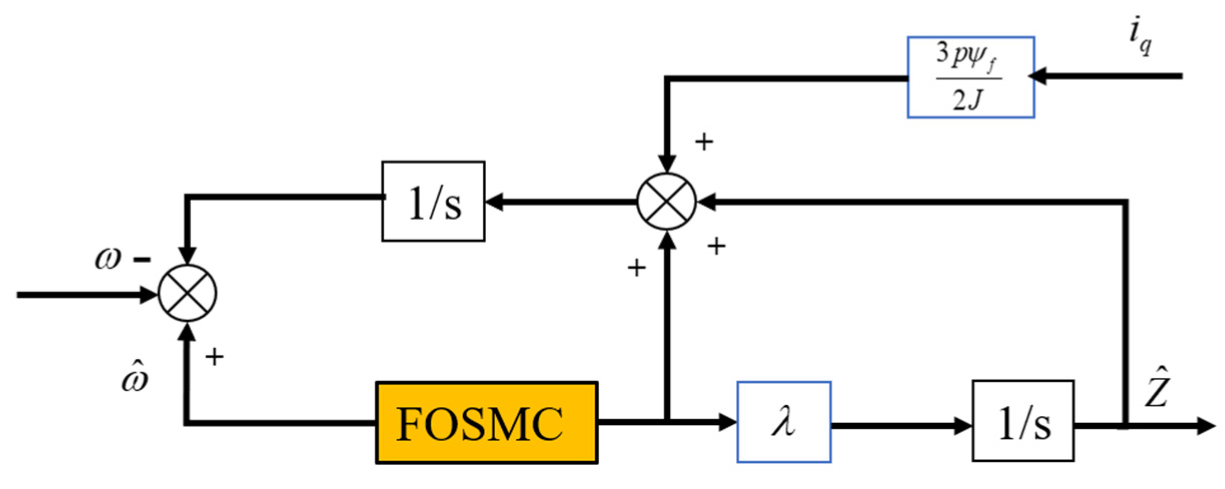
4. Design of Fractional Sliding Mode Observer

To improve the anti-disturbance ability of the controller, a fractional sliding mode observer is used to estimate the disturbance. According to Equation (3), the sliding mode disturbance observer is designed as
d ω d t = 3 p ψ f i q 2 J B ω J + Z d Z d t = η
where η is the rate of change of the unknown perturbed part.
d ω ^ d t = 3 p ψ f i q 2 J B ω ^ J + Z + u s d Z d t = λ u s
where ω ^   is the estimated speed, Z is the sliding mode control law, us is the sliding mode function to be designed, and λ > 0 is the observer gain.
The speed error is defined as
ω ~ = ω ^ ω
The observation error of the unknown disturbance part is
Z ~ = Z ^ Z
By subtracting Equation (10) from Equation (9), we can obtain
d ω ~ d t = B ω ~ J + Z ~ + u s d F ^ d t = λ u s η
Define the sliding mode surface of the load torque fractional sliding mode observer is as follows:
s = c 1 ω ~ + c 2 D v 2 ω ~
In the formula, c 1 and c 2 are the gains of the sliding mode surface to be designed, generally taking positive real numbers; v2 is the order of the fractional sliding mode surface, 0 < v 2 < 1.
The derivation of the above sliding surface can be obtained as follows:
s ˙ = c 1 ω ~ ˙ + c 2 D v 2 + 1 ω ~
Using the new adaptive sliding mode approach law proposed above, the expression of the sliding mode control function u s can be obtained as follows:
u s = S c 2 D v 2 + 1 ω ~ c 1 + B J ω ~ Z ~  
By substituting the sliding mode convergence law S from Equation (46) into Equation (10), we can obtain
u s = ε ( t ) tan ( s ϕ ) k ( t ) s μ sgn ( s ) k 1 s α E n sgn ( s ) c 2 D u + 1 ω ~ c 1 + B J ω ~ Z ~
Figure 3 illustrates the structural block diagram of the fractional sliding mode observer.
Finally, the overall structural block diagram of the proposed system is shown in Figure 4. Note, that in our system, the outer loop for motor control utilizes SMC. In contrast, the inner loop employs a PI controller for current regulation. This configuration is chosen to ensure the system maintains stability and robustness when faced with parameter uncertainties and external disturbances, which are common challenges in motor control. The outer loop SMC effectively addresses these uncertainties, while the inner loop PI controller provides accurate and efficient current regulation using a straightforward and reliable control method. Retaining the PI controller in the inner loop offers a practical balance between control performance and implementation complexity.

5. Simulation Verification

To verify the effectiveness of the AFOSMC strategy based on the fractional sliding mode observer proposed in this paper, a surface mount PMSM simulation model is established in Matlab/Simulink, and the performance is compared with the PMSM based on traditional PI and integer sliding mode control algorithms. Note that the version of Simulink we adopted is 10.7, and the solver uses ode23tb with a variable step size algorithm. Moreover, the Oustaloup recursive approximation was adopted to implement the fractional calculus. We implemented fractional-order operators using the Oustaloup recursive approximation with a frequency band of frequency band [ωl, ωh]. The discretization formula is
G ( s ) = K k = 1 N s + ω k s + ω k
where ωk′ and ωk are recursively defined zeros/poles, respectively.
Other main parameters used in the simulation are listed in Table 2.

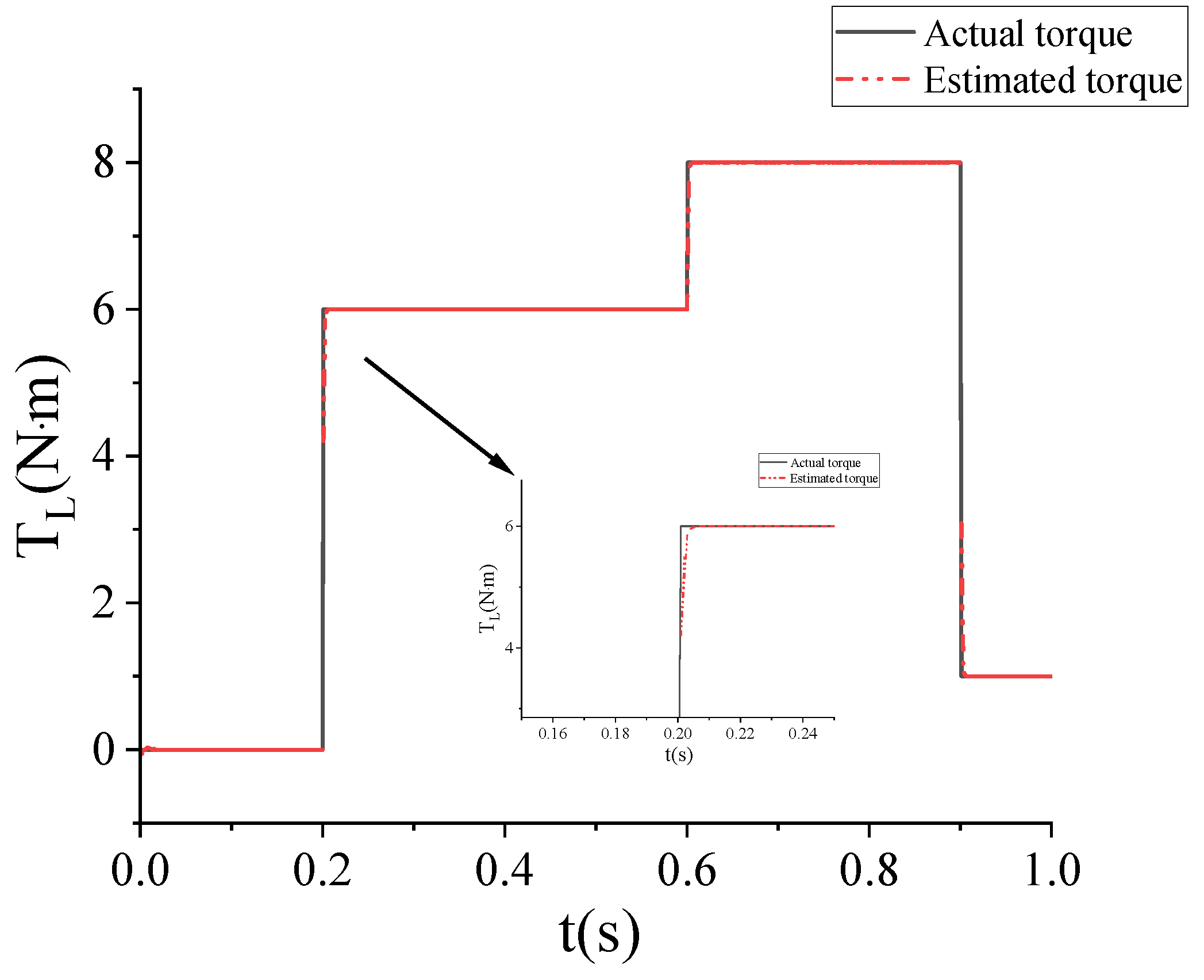
5.1. Performance Test of Fractional Sliding Mode Observer

When the motor starts with no load, it becomes 6 N·m when the load torque is 0.2 s, 8 N·m when it is 0.6 s, and 1 N·m when it is 0.9 s. Figure 5 shows the load torque given value and the observed value curve.
It can be seen that the load torque changes from 0 N·m to 6 N·m at 0.2 s, and the fractional sliding mode observer can accurately observe the load torque with almost no fluctuation. From this, it can be seen that the designed fractional sliding mode observer has a faster convergence speed and higher observation accuracy.

5.2. Controller Performance Testing

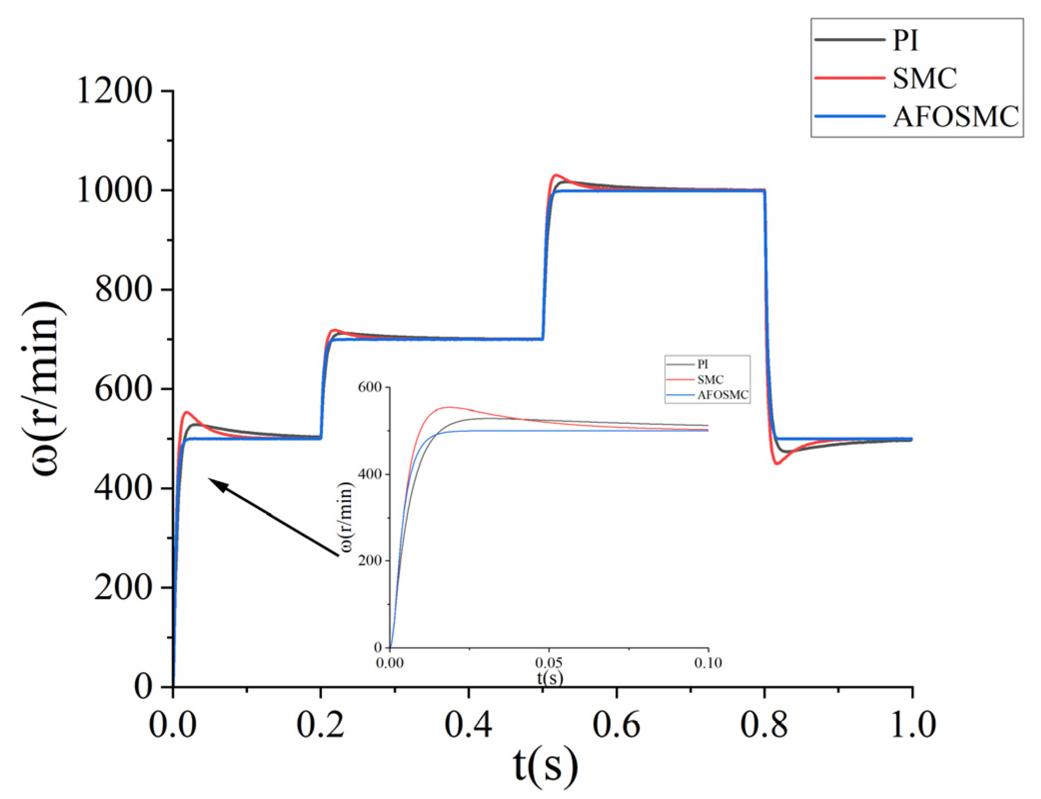
5.2.1. No-Load Start Transmission

To observe the speed response effect of the motor in the no-load starting phase and the variable speed phase, the given motor reference speed is 500 r/min, the motor starts without load, the speed of 0.2 s rises to 700 r/min, 0.5 s rises to 1000 r/min, and the speed of 0.8 s drops to 500 r/min, and the simulation time is 1 s. Table 3 shows the simulation data of three control modes under no-load mode. As shown in Figure 6 and Figure 7, NFOSMC can make the motor reach the given speed quickly without overshooting compared with PI and SMC, and it can compensate sliding mode control based on a sliding mode observer. At the same time, this method enables the motor to respond quickly when the motor speed changes, which proves the effectiveness of the control strategy.

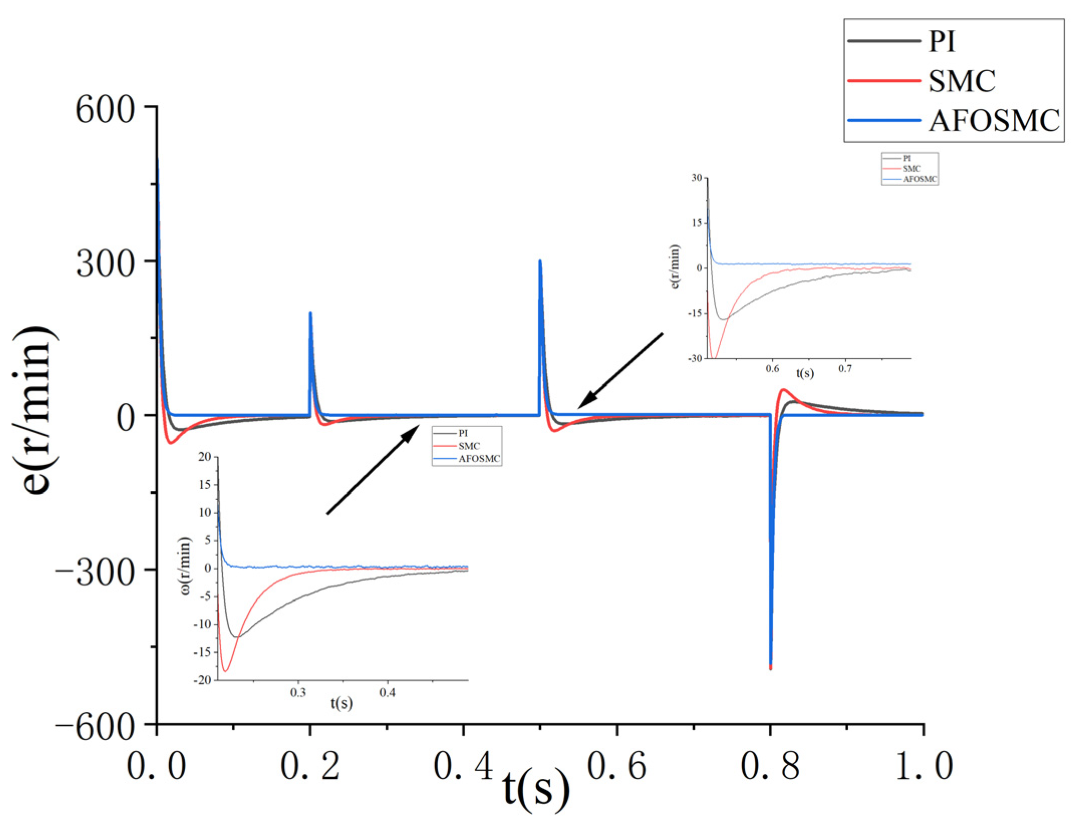
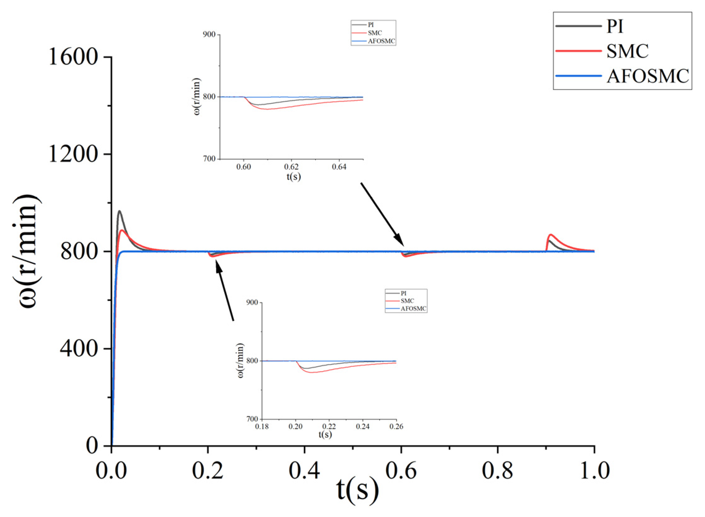
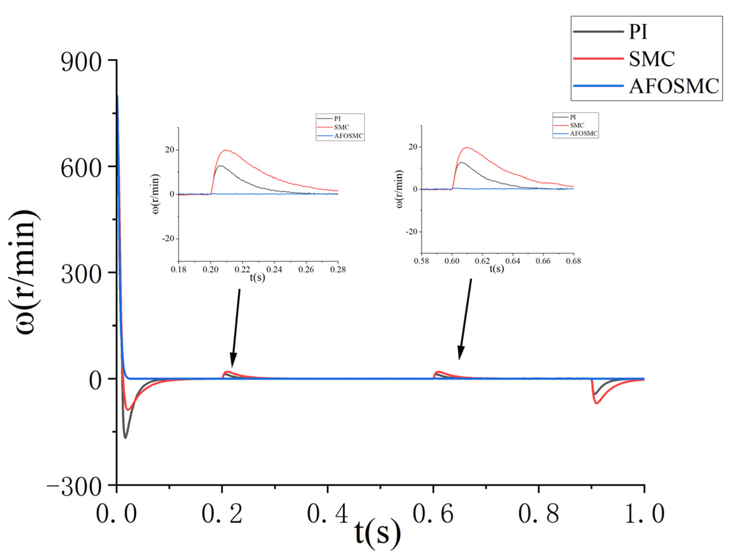
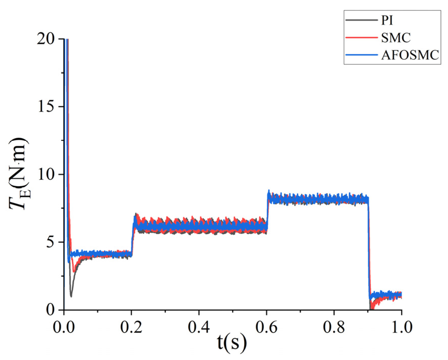
5.2.2. System Response to Sudden Load Changes

The motor reference speed was set to 800 rpm with an initial load torque of 4 N·m. Step changes in load torque were applied at 0.2 s (6 N·m), 0.6 s (8 N·m), and 0.9 s (1 N·m), as illustrated in the load torque profile (Figure 8). The resulting speed response and speed tracking error under these variable load conditions are presented in Figure 9 and Figure 10, respectively, demonstrating the system’s dynamic performance during rapid torque transitions.
Table 4 shows the simulation data of three different control modes under load conditions. The comparative analysis of Figure 9, Figure 10 and Figure 11 demonstrates that the proposed AFOSMC scheme significantly outperforms traditional PI and SMC controllers under complex disturbance conditions. The proposed AFOSMC control scheme performs better than traditional PI and SMC control. It can achieve more accurate speed tracking control, higher observation accuracy, and stronger anti-interference ability.

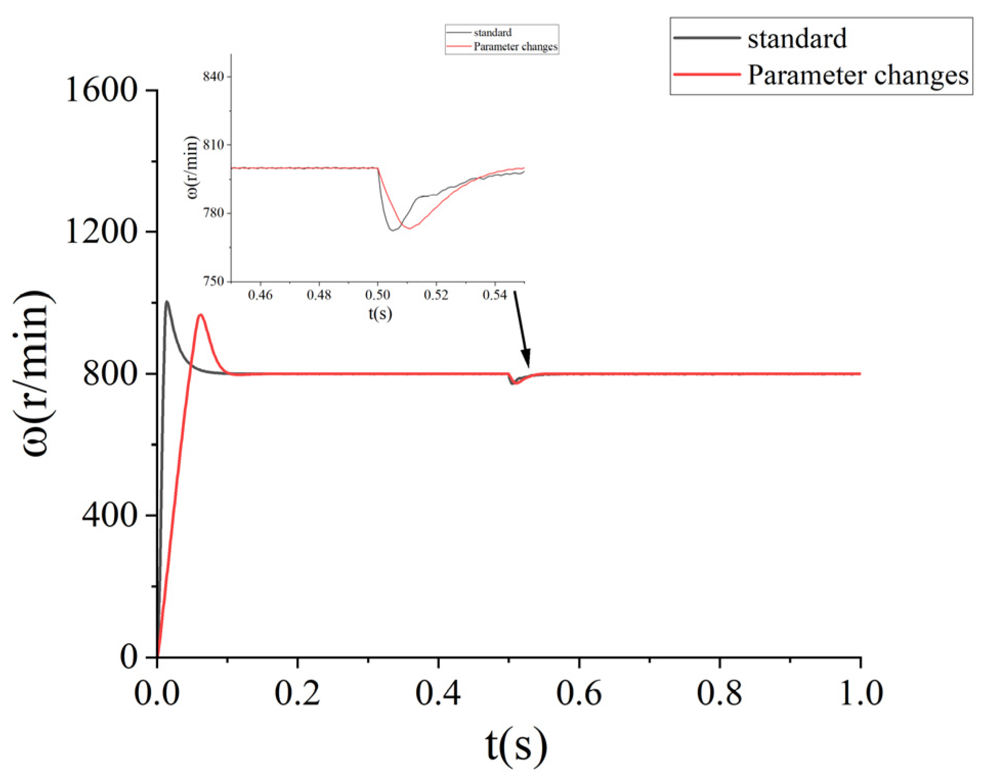
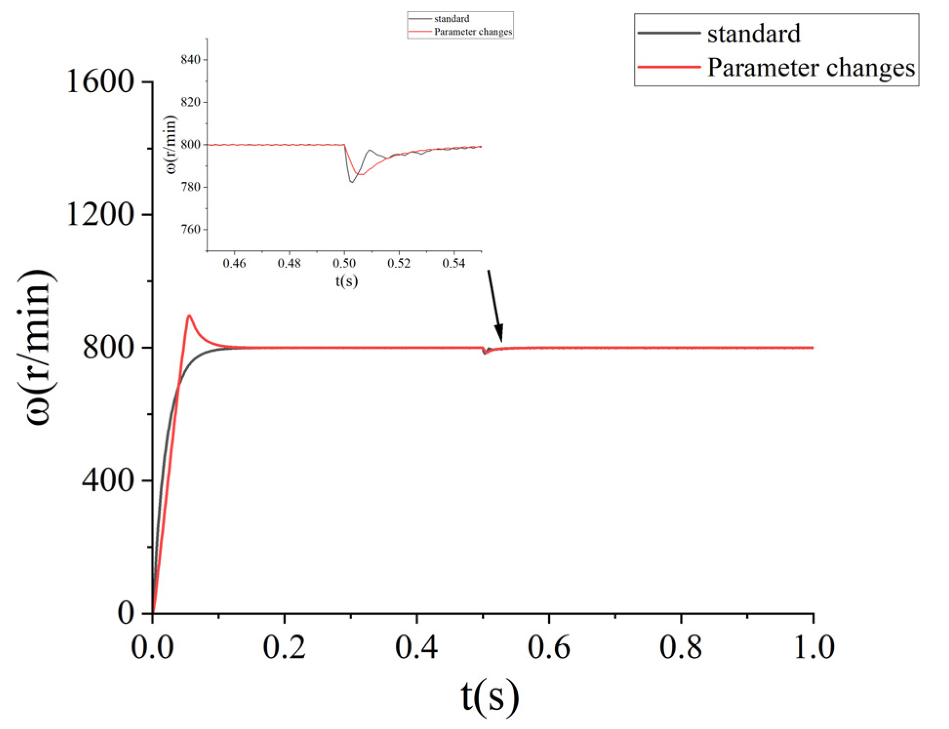
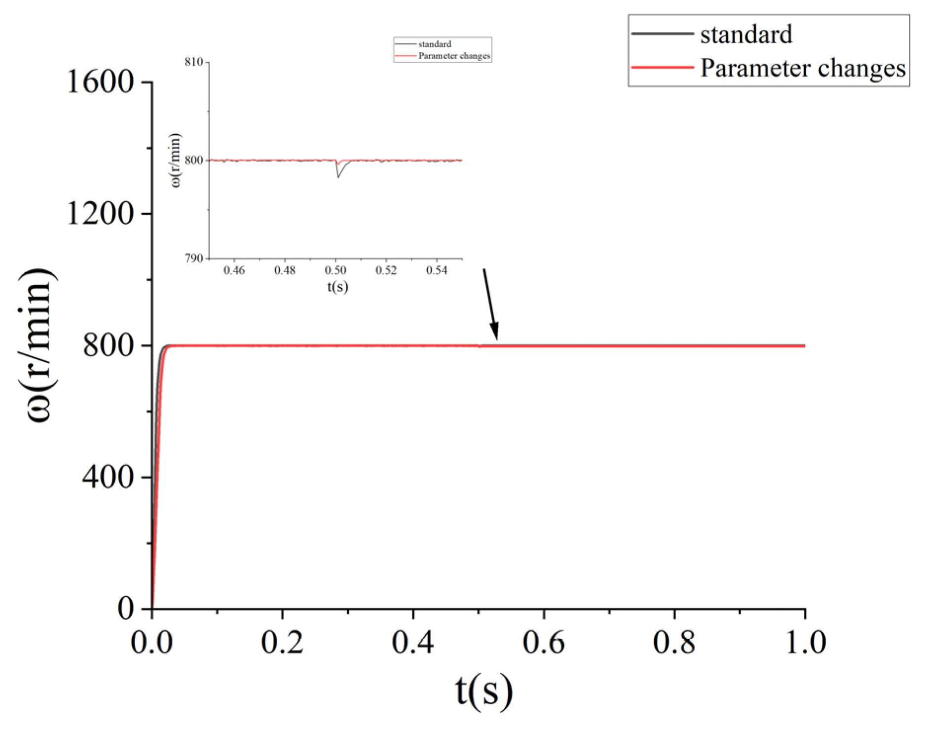
5.3. Parameter Change Test

Due to possible deviations in the mathematical modeling of PMSM control systems, changes in motor parameters are important factors affecting the tracking accuracy of the system. Change the internal parameters of the motor and analyze the response of the PMSM control system under SMC, PI, and AFOSMC. Change the motor parameters J and R used in the controller to three times the corresponding nominal values, while keeping other simulation parameters unchanged. Given a speed of 800 r/min, add a load torque of 4 N·m at 0.5 s. The speed simulation curves under the three control modes are shown in Figure 12, Figure 13 and Figure 14. The simulation data after changes in system parameters are shown in Table 5.
As shown in Figure 12, after adding the load at 0.5 s, the maximum speed deviation of the PI system under the standard parameter state is 27 r/min, which returns to steady state after 58 ms. The maximum speed deviation after parameter change is 28 r/min, which returns to steady state after 45 ms, and the convergence speed is slightly faster than the standard state. Figure 13 shows that after adding the load, the maximum speed deviation of the SMC system in the nominal state is 18 r/min, which returns to steady state after 53 ms. After parameter changes, the maximum speed deviation is 14 r/min, which returns to steady state after 44 ms. Figure 14 shows that after adding the load, the AFOSMC system has a maximum speed deviation of 1.8 r/min in the nominal state, which returns to steady state after 4 ms. After parameter changes, the maximum speed deviation is 0.4 r/min, and the convergence speed is 2 ms faster than the nominal state. As shown in Figure 12, Figure 13 and Figure 14 and Table 5, when the stator resistance and inertia change, the AFOSMC system has a shorter peak time and a smaller overshoot compared to traditional sliding mode control and PI control. At the same time, the control accuracy is also improved, indicating that it is more robust under this control method.

6. Conclusions

To improve the dynamic performance of a PMSM under complex load disturbance, this paper proposes a control system based on fractional sliding mode. Based on the traditional integer sliding mode surface, a new fractional sliding mode surface is designed to optimize the control effect and improve the control accuracy. At the same time, the new adaptive sliding mode reaching law is used to replace the traditional exponential reaching law, which significantly reduces the controller chatter and allows the system to converge quickly. In addition, the fractional sliding mode observer designed in this paper can compensate for the disturbance in real-time. The simulation compares the AFOSMC, SMC, and PI control strategies under no-load start-up and sudden load conditions. The simulation results show that the control method proposed in this paper responds quickly and performs well in terms of stability and resistance to interference, which can meet the high-precision and high-performance requirements of PMSMs in industry and experiments. Table 6 compares our proposed method with representative existing works, emphasizing the novelty and performance of our AFOSMC for PMSM speed control.
Note that the proposed method improves both symmetry preservation in system response and control accuracy under asymmetric conditions. This is supported by the simulation results in several ways. First, using a fractional-order sliding mode controller leads to more balanced and consistent system behavior when the motor experiences sudden or uneven changes in load. For example, when the load torque changes abruptly at different times, the controller maintains accurate speed tracking with minimal error and overshoot, as shown in Figure 9 and Figure 10. This demonstrates that the system response remains stable and symmetrical even under asymmetric disturbances. Second, the fractional-order sliding mode disturbance observer accurately estimates and compensates for external disturbances in real time. This allows the controller to quickly and effectively reject asymmetric load changes, further improving the system’s robustness and control accuracy. The results show that the proposed method achieves faster convergence and smaller speed deviations than traditional PI and SMC controllers, especially when the system parameters or external conditions change unpredictably. Finally, the adaptive approach law reduces chattering and ensures smooth convergence to the desired state, which helps maintain symmetry in the control process. Overall, the simulation results confirm that the proposed method not only handles asymmetric disturbances more effectively but also preserves the desired symmetry and accuracy in system performance. Our future work will experimentally validate the proposed control approach to better demonstrate its effectiveness.

Author Contributions

Conceptualization, F.B.; methodology, F.B.; software, F.B.; validation, F.B.; formal analysis, F.B. and Y.-R.C.; investigation, Y.-R.C.; resources, Y.-R.C.; writing—original draft, F.B. and Y.-R.C.; writing—review and editing, F.B. and Y.-R.C.; supervision, Y.-R.C. All authors have read and agreed to the published version of the manuscript.

Funding

This research has no external funding.

Data Availability Statement

The original contributions presented in this study are included in the article. Further inquiries can be directed to the corresponding author.

Conflicts of Interest

Author Fengshuo Bian was employed by the company Ruidian Technology Co., Ltd. The remaining authors declare that the research was conducted in the absence of any commercial or financial relationships that could be construed as a potential conflict of interest. No funding was received from the company Ruidian Technology Co., Ltd.

References

  1. Cheng, X.; Yao, L.; Han, P.; Zhou, R.; Zhu, J. Active damping control based bus voltage resonance suppression in electrolytic capacitorless PMSM application. J. Phys. Conf. Ser. 2024, 2853, 012010. [Google Scholar] [CrossRef]
  2. Xia, T.; Peng, F.; Huang, Y. A novel energy balance control method for a modular multilevel converter in a high-speed PMSM drive application. Energies 2023, 16, 5022. [Google Scholar] [CrossRef]
  3. Muthusamy, M.; Hendershot, J.; Pillay, P. Design of a spoke type PMSM with SMC stator core for traction applications. IEEE Trans. Ind. Appl. 2022, 59, 1418–1436. [Google Scholar] [CrossRef]
  4. Wei, Z.; Deng, Y.; Qiao, T.; Fei, Q.; Li, H. Gaussian process-based parameter identification and model current predictive control strategy of PMSM. Opt. Precis. Eng. 2023, 31, 479–490. [Google Scholar] [CrossRef]
  5. Zhu, G.; Li, L.; Xue, M.; Liu, T. A full-domain fluidic-thermal approach for a high-speed PMSM considering the bearing components. IET Electr. Power Appl. 2022, 16, 169–177. [Google Scholar] [CrossRef]
  6. Karakatsanis, T.S. Overview of IoT security challenges and sensors specifications in PMSM for elevator applications. Machines 2024, 12, 839. [Google Scholar] [CrossRef]
  7. Kartal, E.T.; Arabul, F.K. Effects of air gap eccentricity on different rotor structures for PMSM in electric vehicles. Sci. Rep. 2024, 14, 17335. [Google Scholar] [CrossRef]
  8. Kesavan, P.K.; Subramaniam, U.; Almakhles, D.J. Laboratory implementation of direct torque controller based speed loop pseudo derivative feedforward controller for PMSM drive. CES Trans. Electr. Mach. Syst. 2024, 8, 12–21. [Google Scholar]
  9. Li, H.; Zhang, R.; Shi, P.; Mei, Y.; Zheng, K.; Qiu, T. Sensorless control of a PMSM based on an RBF neural network-optimized ADRC and SGH-CKF-STF algorithm. Meas. Control 2024, 57, 266–279. [Google Scholar] [CrossRef]
  10. Tong, Z.; Meng, B.; Wang, F.; Liu, J.; Liu, Y.; Lin, S.; Ding, B.; Feng, G. Dual position offset injection based multi-parameter decoupled estimation of PMSM considering signal injection induced inductance variation. IEEE Trans. Ind. Appl. 2024, 60, 6913–6922. [Google Scholar] [CrossRef]
  11. Zhang, W.; Xu, Q.; Zhang, Y.; Wang, Y.; Yang, Y.; Cai, H. Multi-objective tree-structured parzen estimator optimized Res-Net for ITSC fault diagnosis of PMSM. IEEE Access, 2024; early access. [Google Scholar]
  12. Singh, V.; Majumder, M.G.; Rajashekara, K.; Reddy, S.R.P. Parameter estimation for sensorless position control of PMSM drives with long cables in subsea applications. IEEJ J. Ind. Appl. 2023, 12, 303–311. [Google Scholar] [CrossRef]
  13. Skowron, M. Analysis of PMSM short-circuit detection systems using transfer learning of deep convolutional networks. Power Electron. Drives 2024, 9, 21–33. [Google Scholar] [CrossRef]
  14. Zhang, W.; Li, M.; Gao, Y.; Chen, Y. Periodic adaptive learning control of PMSM servo system with LuGre model-based friction compensation. Mech. Mach. Theory 2022, 167, 104561. [Google Scholar] [CrossRef]
  15. Kojabadi, H.; Ghribi, M. MRAS-based adaptive speed estimator in PMSM drives. In Proceedings of the 9th IEEE International Workshop on Advanced Motion Control, Istanbul, Turkey, 27–29 March 2006. [Google Scholar] [CrossRef]
  16. Lu, L.; Wang, X.; Jin, L.; Liu, Q.; Zhang, Y.; Mao, Y. Current optimization-based control of dual three-phase PMSM for low-frequency temperature swing reduction. Def. Technol. 2024, 34, 238–246. [Google Scholar] [CrossRef]
  17. Wang, X.; Li, Q. Analysis of bending and torsional modal of PMSM rotor systems for EV. J. Phys. Conf. Ser. 2024, 2782, 012025. [Google Scholar] [CrossRef]
  18. Pan, F. Research and simulation of high-efficiency disturbance rejection speed control strategy for PMSM. J. Phys. Conf. Ser. 2024, 2803, 012038. [Google Scholar] [CrossRef]
  19. Kumar, P.; Ajmeri, M.; Singh, A.K.; Mandal, R.K. Novel high-gain boost converter with experimentally validated ADRC control technique for renewable energy applications. Electr. Eng. 2025, 107, 899–908. [Google Scholar] [CrossRef]
  20. Carlson, F.B. Linear ADRC is equivalent to PID with set-point weighting and measurement filter. IEEE Trans. Ind. Electron. 2025; early access. [Google Scholar]
  21. Chi, X.; Wang, C.; Wu, Q.; Yang, J.; Lin, W.; Zeng, P.; Li, H.; Shao, M. A ripple suppression of sensorless FOC of PMSM electrical drive system based on MRAS. Results Eng. 2023, 20, 101427. [Google Scholar] [CrossRef]
  22. Qiu, J. Design and simulation of the fuzzy PID control system for PMSM. J. Phys. Conf. Ser. 2024, 2820, 012097. [Google Scholar] [CrossRef]
  23. Zhang, X.; Zhang, C.; Xu, C.; Fan, S. Multimode model predictive control for PMSM drive system. IEEE Trans. Transp. Electrific. 2023, 9, 667–677. [Google Scholar] [CrossRef]
  24. Wang, M.; Liu, Y.; Wang, Q.; Liao, Y.; Wheeler, P. Speed-current single-loop control of PMSM based on model-assisted cascaded extended state observer and sliding mode control. Int. J. Circuit Theory Appl. 2024, 52, 3558–3583. [Google Scholar]
  25. Jankowska, K.; Dybkowski, M. Experimental analysis of the current sensor fault detection mechanism based on neural networks in the PMSM drive system. Electronics 2023, 12, 1170. [Google Scholar] [CrossRef]
  26. Guo, H.; Gu, Y.; Huang, Y.; Zhou, J.; Wang, X. A study on the characteristics of schizophrenia patients with violent crimes based on clinical, prefrontal functional connectivity, and polygenic risk scores. Int. J. Neuropsychopharmacol. 2025, 28, i225–i226. [Google Scholar] [CrossRef]
  27. Ahn, H.; Kim, S.; Park, J.; Chung, Y.; Hu, M.; You, K. Adaptive quick sliding mode reaching law and disturbance observer for robust PMSM control systems. Actuators 2024, 13, 136. [Google Scholar] [CrossRef]
  28. Liu, J.; Li, M.; Xie, E. Noncascade Structure Equivalent SMC for PMSM Driving Based on Improved ESO. IEEE Trans. Power Electron. 2025, 40 Pt 1, 611–624. [Google Scholar] [CrossRef]
  29. Karabulut, Y.; Meşe, E.; Ayaz, M. Comparison study on SMC and grain-oriented laminated steel core for small-size axial flux permanent-magnet synchronous machines. Mater. Res. Express 2024, 11, 106102. [Google Scholar] [CrossRef]
  30. Song, Z.; Xiao, X.; Yang, J.; Tao, T.; Mei, X. A novel sliding mode control with MRAS inertia identification for permanent magnet synchronous motors. Meas. Control 2024, 57, 240–250. [Google Scholar] [CrossRef]
  31. Zhu, M.; Cao, Y.; He, Z.; Wu, Q.; Ma, J.; Qiu, B.; Luo, C. Research on fractional-order sliding mode PMSM speed regulation based on load observer. J. Electr. Eng. Technol. 2024, 19, 3429–3438. [Google Scholar] [CrossRef]
  32. Zwerger, T.; Mercorelli, P. Optimal control strategies for PMSM with a decoupling super twisting SMC and inductance estimation in the presence of saturation. J. Frankl. Inst. 2024, 361, 106934. [Google Scholar] [CrossRef]
  33. Gao, P.; Zhang, G.; Ouyang, H.; Mei, L. An Adaptive Super Twisting Nonlinear Fractional Order PID Sliding Mode Control of Permanent Magnet Synchronous Motor Speed Regulation System Based on Extended State Observer. IEEE Access 2022, 8, 53498–53510. [Google Scholar]
  34. Song, J.; Zheng, W.X.; Niu, Y. Self-triggered sliding mode control for networked PMSM speed regulation system: A PSO-optimized super-twisting algorithm. IEEE Trans. Ind. Electron. 2022, 69, 763–773. [Google Scholar] [CrossRef]
  35. Liu, J.-F.; Feng, Y.; Yu, J.-Y.; Tang, J.-W.; Zhang, L. Fractional order second-order sliding mode MRASO for SPMSM. Meas. Control. 2024, 57, 863–870. [Google Scholar]
  36. Zheng, W.; Chen, Y.; Wang, X.; Huang, R.; Lin, M.; Guo, F. Fractional order sliding mode control for permanent magnet synchronous motor speed servo system via an improved disturbance observer. Int. J. Control Autom. Syst. 2023, 21, 1143–1153. [Google Scholar]
  37. Gao, P.; Pan, H.H. Model-free double fractional-order integral sliding mode control for permanent magnet synchronous motor based electric mopeds drive system. IEICE Electron. Express 2023, 20, 20230178. [Google Scholar] [CrossRef]
  38. Yang, X.; Chen, W.; Yin, C.; Cheng, Q. Fractional-Order Sliding-Mode Control and Radial Basis Function Neural Network Adaptive Damping Passivity-Based Control with Application to Modular Multilevel Converters. Energies 2024, 17, 580. [Google Scholar] [CrossRef]
  39. Benaddy, A.; Labbadi, M.; Elyaalaoui, K.; Bouzi, M. Fixed-Time Fractional-Order Sliding Mode Control for UAVs under External Disturbances. Fractal Fract. 2023, 7, 775. [Google Scholar] [CrossRef]
  40. Shah, P.; Agashe, S. Review of fractional PID controller. Mechatronics 2016, 38, 29–41. [Google Scholar] [CrossRef]
  41. Gao, W.; Wang, Y.; Homaifa, A. Discrete-time variable structure control systems. IEEE Trans. Ind. Electron. 1995, 42, 117–122. [Google Scholar] [CrossRef]
Figure 1. Error varies with time.
Symmetry 17 00736 g001
Figure 2. Controller u varies with time.
Symmetry 17 00736 g002
Figure 3. Fractional sliding mode observer.
Symmetry 17 00736 g003
Figure 4. Overall structural block diagram.
Symmetry 17 00736 g004
Figure 5. Load torque estimation.
Symmetry 17 00736 g005
Figure 6. No-load speed.
Symmetry 17 00736 g006
Figure 7. Rotational speed error.
Symmetry 17 00736 g007
Figure 8. Given load.
Symmetry 17 00736 g008
Figure 9. Speed under different loads.
Symmetry 17 00736 g009
Figure 10. Rotational speed error.
Symmetry 17 00736 g010
Figure 11. Electromagnetic torque.
Symmetry 17 00736 g011
Figure 12. Speed curve under PI control.
Symmetry 17 00736 g012
Figure 13. Speed curve under SMC control.
Symmetry 17 00736 g013
Figure 14. Speed curve under AFOSMC control.
Symmetry 17 00736 g014
Table 1. Two simulation parameters of the convergence law.
ERLARL
ɛ = 5η1 = 0.5
k = 15δ = 0.1
η2 = 0.7, ζ = 1
A = 0.6
k1 = 1, μ = 0.6
Table 2. PMSM simulation parameters.
ParametersValues
Pole-pairs4
Stator resistance2.875 Ω
Stator inductance8.5 × 10−3 H
Permanent magnet flux link0.175 Wb
Inertia0.0003 kg·m2
Viscous friction coefficient0 N·m·s
Table 3. No load startup simulation data.
Performance IndexPISMCAFOSMC
Settling time/ms15011020
Overshoot ratio/%5.6100.15
Steady-state error/r31.10.13
Table 4. Load start simulation data.
Performance IndexPISMCAFOSMC
Settling time/ms9810320
Overshoot ratio/%20.7510.370.02
Steady-state error/r0.50.30.16
Table 5. Simulation data after changing motor parameters.
Performance IndexPISMCAFOSMC
Settling time/ms10910627
Overshoot ratio/%20.75120.125
Steady-state error/r0.40.20.1
Table 6. Comparison between the proposed method and existing PMSM speed control methods.
MethodControl MethodDisturbance
Observer
Adaptive
Mechanism
Fractional-OrderNovel Reaching LawChattering
Suppression
PIPINoNoNoN/ANo
SMCInteger-order SMCOptionalNoNoExponentialLimited
Super Twisting SMCSTW SMCYesParameter TuningNoSuper-TwistingYes
FOSMCFractional-Order SMCYesSomeYesStand/ModifiedYes
ProposedAdaptive FOSMC (AFOSMC)Fractional SMCFully AdaptiveYesNovel AVERLExcellent
Disclaimer/Publisher’s Note: The statements, opinions and data contained in all publications are solely those of the individual author(s) and contributor(s) and not of MDPI and/or the editor(s). MDPI and/or the editor(s) disclaim responsibility for any injury to people or property resulting from any ideas, methods, instructions or products referred to in the content.

