Abstract
The dynamic response of symmetrical press mechanisms is severely affected by revolute clearance, translational clearance, and the elasticity of the components. Therefore, the coupling effects of disturbance factors were studied in this paper, including revolute clearance, translational clearance, and component elastic deformation; the influence of their coupling effects on the dynamic chaos characteristic are also discussed. A dynamic model of a rigid–flexible coupling mechanism with revolute clearance and translational clearance was established. Using MATLAB R2024a to solve the model, chaos identification was researched through phase diagrams, Poincaré maps, and maximum Lyapunov exponents. Under the parameters studied in this paper, the maximum Lyapunov exponents at revolute clearance A (X direction and Y direction) and translational clearance B (X direction and Y direction) were 0.0521, 0.0573, 0.3915, and −0.0287, respectively. The motion state of revolute pair A (X direction and Y direction) and translational pair B (X direction) were more prone to chaotic states; translational pair B (Y direction) was more prone to periodic motion. The influence of various factors on the dynamic response were analyzed. With the increase in driving speed and clearance value, as well as the decrease in friction coefficient, the stability of the mechanism weakened, and the vibration of the mechanism’s dynamic response intensified. This paper provides theoretical support for the establishment of precise dynamic models for multi-link symmetrical structure press mechanisms.
1. Introduction
The clearance between two relative moving members in a symmetrical structure press mechanism is inevitable, and this can cause collisions between two connecting components [1,2,3]. The collision force of the clearance will seriously affect the dynamic of the symmetrical structure press mechanism and reduce its dynamic performance. Revolute and translational pairs are the two most common types of motion pairs, so studying the coupling effect of these two types of motion pairs on mechanism dynamics is highly relevant. When the mechanism operates at a fast speed and is subjected to certain external forces, the components are prone to elastic deformation [4,5,6]. Therefore, when the mechanism is in a rapid motion state, it is necessary to comprehensively consider the coupling effects of disturbance factors, such as translational clearance, revolute clearance, and elastic deformation, and analyze the impact of their coupling effects on the mechanism’s motion state.
In recent years, the effect of revolute clearance on the dynamics of mechanisms has attracted much scholarly attention, and, therefore, research has been conducted on the dynamic performance of mechanisms with revolute pair clearance. Revolute clearance can cause inaccurate motion transmission of the mechanism, resulting in deviation between the output motion and the theoretical value, which affects the dimensional accuracy and surface quality of the machined parts. Revolute clearance can cause collisions and impacts between components, resulting in vibration and noise, which in turn affects the dynamic performance of the mechanism. Chen et al. [7] proposed a computational method for the dynamic modeling and analysis of planar multi-link mechanisms with multiple degrees of freedom and multiple clearances, and they investigated the dynamic characteristics of the planar multi-link mechanism. Li et al. [8] used the finite particle method to analyze the dynamic behavior of Bennett linkage with revolute clearance pairs. The motion of the proposed model agrees well with that of the higher-fidelity model, but the authors did not consider situations when journals and bearings are in line contact and surface contact. Wang et al. [9] established a rigid–flexible coupled multibody dynamic model of a tracked armored vehicle using the transfer matrix method for multibody systems, and they analyzed the influence of trunnion bearing clearance on the vibration characteristics of a tracked armored vehicle. The proposed method avoids the global dynamics equations of the system, keeps a high computational speed, and allows for highly formalized modeling. The proposed method successfully simplifies the modeling process but reduces the accuracy of solving problems involving a large amount of nonlinear friction. Chen et al. [10] proposed a dynamic response error and precision reliability analysis method for mechanisms with revolute clearance pairs. Fu et al. [11] proposed a compound control method for the reliability of robotic arms with clearance pairs. However, these two proposed methods involve a certain degree of subjectivity in selecting the allowable error range. In contrast, Jia et al. [12] established a dynamic response reliability model for a 4-UPS/RPS spatial parallel mechanism with clearance pairs and uncertain parameters using the metamodeling approach, significantly improving the accuracy of reliability calculations. Jiang et al. [13] proposed a precise modeling method for the nonlinear dynamics of a multi-link mechanism under the coupling effects of clearance and elastic deformation, successfully exploring the impact of component flexibility on the system’s dynamic response. However, the proposed method involves a large computational load, and the accuracy of deformation description may decrease under complex deformation conditions. Liang et al. [14] studied the dynamic characteristics of a planar R-2RRP-RRR mechanism with clearance based on the Newton–Euler method, and the validity of the dynamic model was verified through numerical calculations and multibody dynamics simulations. Chen et al. [15] analyzed the dynamic response and nonlinear characteristics of a planar six-bar mechanism, and they investigated the effect of clearance lubrication on the mechanism using the improved Pinkus–Sternlicht model. The proposed method demonstrates high numerical stability and modeling rationality, but extending it to the case of lubrication in translational pairs is more challenging. Guo et al. [6] proposed a new type of revolute clearance contact model considering surface topography. Chen et al. [16] studied the effect of impact load on the dynamics of a mechanism with clearance, and a test prototype was built. Ma et al. [17] used spectral element methodology to research the dynamics of a planar structure with clearance, and they revealed the wave propagation law in the planar structure with a rotating gap joint. Wu et al. [18] proposed a passive chaos suppression methodology. The effectiveness and correctness of the method were verified by a phase diagram, and so on. Lin et al. [19] established a nonlinear dynamics model of a mechanism with revolute clearance, and a reliability model of motion accuracy based on a strength–stress interference method was proposed. Gao et al. [20] studied a failure mechanism and the reliability of the mechanism with lubrication clearance. The applicability of the model was verified by the Monte Carlo method. Wang et al. [21] studied the influence of clearance between kinematic pairs; a degeneration and impact model of mechanical transmission mechanism was proposed. Chen et al. [22] established a dynamic model of a 3-RRRR mechanism with clearance, and simulation verification was carried out with ADMAS. Based on the Achard model, Bai et al. [23] predicted wear characteristics of clearance in the mechanism. Huang et al. [24] combined clearance with time-varying mesh stiffness, and nonlinear dynamics analysis of a gear transmission model with rotation pair clearance was carried out. Huang et al. [25] presented a monitoring method of revolute clearance that integrated dynamic and thermal image features.
A translational pair is generally used as a connection between the end effector of a mechanism and the frame. The translational clearance model is more difficult and complex compared to a revolute clearance pair, and scholars have relatively less research on it compared to revolute clearance pairs. The clearance between translational pairs causes the components to shake and jam during the movement process, affecting the smoothness of the mechanism’s motion. Due to the presence of clearance, a translational pair is prone to relative sliding and collision during motion, accelerating component wear and shortening the service life of the mechanism. Zhuang et al. [26] proposed a modeling and simulation method for a rigid multibody system with frictional translational pairs; the problem of the transitions of the contact situation of normal forces acting on sliders and the transitions of the stick–slip of the sliders in the system was formulated as a horizontal linear complementarity problem. Wang et al. [27] established a contact force model for the slider and guide rail in a three-dimensional translational pair, and they analyzed the dynamic chaotic phenomena and behavior of the three-dimensional crank–slider mechanism. This study fills the research gap regarding the clearance in three-dimensional translational pairs to some extent. Xiao et al. [28] studied the nonlinear dynamics of the crank–slider mechanism considering rod flexibility and translational pair clearance. Based on the finite element method, Zhang et al. [29] established a dynamic model of the crank–slider mechanism considering translational clearance. Combined with the numerical calculation method, Qian et al. [30] proposed a contact detection methodology, which was applied to the crank–slider mechanism with translational clearance. Wu et al. [31] studied a double crank mechanism with translational clearance, and simulation verification was carried out with ANSYS/LS-DYNA. Zheng et al. [32] presented a modeling methodology for a planar mechanism considering translational clearance, and the uncertainty problem from a stationary analysis of the mechanism was solved. Liu et al. [33] proposed a dynamic equation of a mechanism with translational clearance, and the effect of the flexibility of component and clearance lubrication on dynamic performance was analyzed. Flores and Zhuang et al. [34,35] proposed a dynamic modeling method for a rigid system with translational clearance. Liu et al. [36] researched a new tribo-dynamic coupling model of a lubricated translational joint in two-stroke marine engines to research dynamic characteristics.
In order to establish an accurate dynamic model, it is necessary to simultaneously consider the coupling effect of revolute clearance and a translational clearance pair to reveal the impact of their coupling effect on dynamics, which has attracted the attention of some researchers. However, previous studies mainly concentrated on the dynamic response of simple, four-bar, rigid-body mechanisms, and there are relatively few studies on the nonlinear characteristics of a complex flexible mechanism. Components undergo elastic deformation when subjected to force, which may result in deviations between the actual and ideal movements of the mechanism. Meanwhile, the flexible deformation of the components consumes some energy, resulting in a decrease in the energy transfer efficiency of the mechanism. Therefore, it is necessary to study the influence of component elastic deformation on mechanisms. Ting et al. [37] proposed a kinematic model to quantify the impact of joint clearance accumulation on the nominal output link position of a linkage comprising rotational and prismatic joints, and they successfully reduced complexity and computational load. Bai et al. [38] established a planar crank–slider mechanism model considering revolute and translational clearances, and its dynamics response was studied by calculation and experiment methods. Tan et al. [39], taking the crank–slider mechanism and considering mixed clearance as the research object, derived a dynamics equation based on the first type of the Lagrange multiplier method, and the dynamics response of the mechanism under four different situations was compared and analyzed. Dong et al. [40] established the dynamic equation of a flexible toggle link mechanism with the lubrication revolute and translational clearance. Jiang et al. [41] established a dynamics model with mixed clearance, and nonlinear dynamic characteristics were studied. Jiang et al. [42] compared the effects of different gap types on dynamics, and then the chaotic phenomenon, accuracy, and stability of the mechanism were studied. Chen et al. [43] analyzed the effect of mixed clearance on the dynamics of slider motor output, driving torque, contact force, and so on. Xiao et al. [44] presented a dynamic modeling method of a flexible multilink mechanism with mixed clearances. Wu and Tan et al. [45,46] used a phase diagram and bifurcation diagram to describe the nonlinear dynamics of a slider–crank mechanism with mixed clearance. Jia et al. [47] proposed a dynamic modeling method of a parallel mechanism with three-dimensional mixed clearance. Three-dimensional motion models of spherical joint clearance and rotating clearance are derived.
Previous research has mostly focused on the influence of pure revolute clearance or pure translational clearance on the dynamics of mechanisms. Due to the difficulty of coupling translational clearance, revolute clearance, and flexible component models into a multi-link mechanism and the difficulty of solving them using MATLAB, there is relatively little research on the comprehensive coupling effects of translational clearance, revolute clearance, and flexible components, as well as their coupling effects on the dynamic characteristics and chaos of complex multi-link mechanisms. Therefore, this paper has innovative and research significance for the content of the mechanism, considering the coupling effects of translational clearance, revolute clearance, and flexible components, and can more accurately predict the motion characteristics and performance of the mechanism.
The arrangement of this paper is as follows: in Section 2, mathematical motion models for translational and revolute clearances are established; in Section 3, theoretical models of rigid beam elements and flexible two elements are established; in Section 4, a dynamic model of a rigid–flexible coupled symmetrical structure press mechanism that considers both revolute and translational clearances simultaneously is established; and in Section 5, chaos identification and an analysis of the influence of various factors on the dynamics of the symmetrical structure press mechanism are studied. In Section 6, the conclusion is discussed.
2. Establishment of a Clearance Model
In the manufacturing process of mechanical parts, due to the limitations of processing technology and equipment, it is difficult to precisely process the size and shape of kinematic pair elements, resulting in clearance. In order to facilitate the assembly of the kinematic pair and ensure that the parts can be smoothly installed in the designated position, it is also necessary to leave appropriate clearance between the kinematic pair elements. Mechanical mechanisms are affected by various factors during operation, such as temperature changes, stress deformation, etc. The reserved clearance between the kinematic pair can compensate for the size changes caused by these factors, ensuring that the kinematic pair can work normally under different working conditions [48,49]. Therefore, it is necessary to study the clearance between kinematic pairs.
2.1. Clearance of the Translational Pair
2.1.1. Mathematical Model of Clearance of the Translational Pair
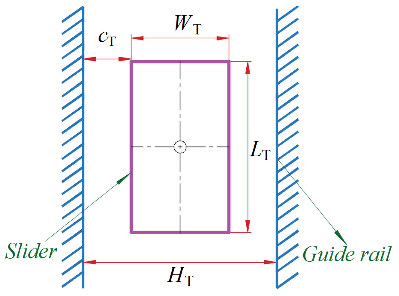
Figure 1 shows a model of clearance of the translational pair, HT is the horizontal distance between upper and lower boundaries of the guide rail, WT is the width of the slider, LT is the length of the slider, and cT is clearance size, with cT = (HT − WT)/2.
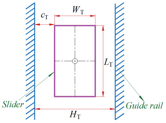
Figure 1.
Model of clearance of the translational pair.
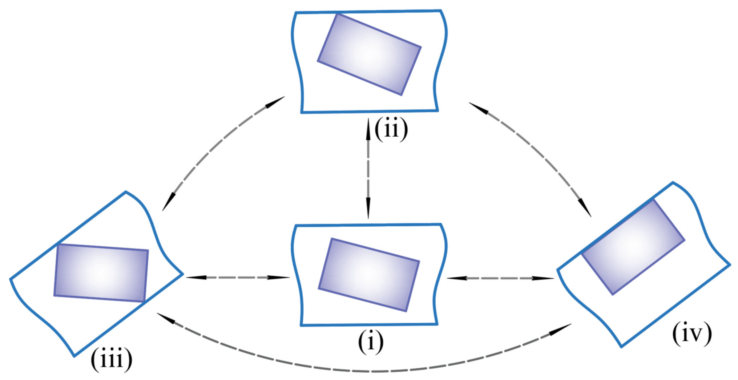
Motion modes of translational clearance are mainly divided into four situations; the motion mode of translational clearance is shown in Figure 2. The slider is in a free state without any collision phenomenon, as shown in Figure 2(i); a corner of the slider collides with the guide rail surface, as shown in Figure 2(ii); the diagonal of the slider collides with the guide rail surface, as shown in Figure 2(iii); and the same side of the slider collides with the guide rail surface, as shown in Figure 2(iv).
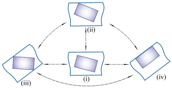
Figure 2.
Motion mode of translational clearance.
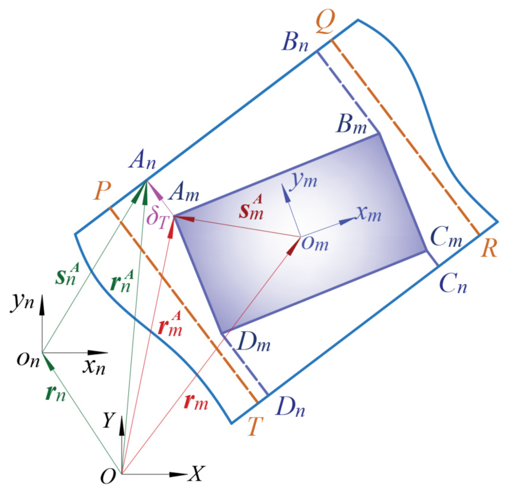
Establishing an effective contact detection model is one of the key aspects of this study, as the clearance between the moving pair can cause contact collisions between the slider and guide rail. Figure 3 shows the contact detection model, which divides the clearance of the moving pair into two parts: slider m and guide rail n. Am, Bm, Cm, and Dm are potential contact points on the slider, and An, Bn, Cn, and Dn are four corner points of the guide rail. Unit normal vector nT is set to [1, 0]T, and the unit horizontal vector tT is set to [0, 1]T. Due to the vertical placement of the guide rail, the unit normal vector is perpendicular to the guide rail. Taking the contact detection of the slider corner point A as an example, there exists a geometric relationship as follows:
where rm and rn are position vectors of the centroid of the slider and guide rail, respectively; Tm and Tn are the transformation matrix of the slider and guide rail, respectively.

Figure 3.
Contact detection model.
When the angle A of the slider collides with the guide rail, the judgment conditions are as follows:
When angle A of the slider collides with the guide rail, the judgment condition is as follows:
2.1.2. Collision Force Model for the Translational Clearance Pair
There are various forms of contact between guide rails and sliders. In order to improve accuracy of established model, suitable normal contact force models need to be adopted for different contact forms to measure the normal contact force. Contact mode between slider and guide rail are shown in Figure 4. For angular contact, due to the small contact area, a small fileted corner can be considered at the corner of the slider, which could be regarded as contact between a sphere and a plane, as illustrated in Figure 4i. The following contact force model considering energy dissipation effect is adopted:
where KT is the stiffness coefficient; ce is the coefficient of recovery; is initial collision velocity; and are the Poisson’s ratio; Em and En are the elastic moduli, respectively; and Rmn represents radius of curvature of slider corner.
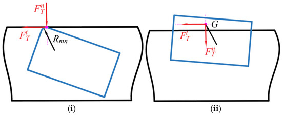
Figure 4.
Contact mode between slider and guide rail. (i) Contact between plane and sphere. (ii) Surface contact.
When two adjacent corners of the slider come into contact with the guideway, contact force acts on the centroid of penetration area, as illustrated in Figure 4ii. The collision force can be expressed as
where is the thickness of the slider.
Friction, as a complex force, has a significant impact on dynamics, and selecting a reasonable friction model is crucial. A modified version of the Coulomb friction model presented by Ambrosio is used [50].
where cf is the coefficient of friction, and cd is the coefficient of correction.
where v0 and v1 are limit values of the given speed.
2.2. Clearance of the Revolute Pair
2.2.1. Mathematical Model of Clearance of the Revolute Pair
The clearance model of the rotating pair is shown in Figure 5. and are the bearing and shaft radius, respectively. and are the centers of the bearing and shaft, respectively. and are the collision points on the bearing and shaft, respectively. The eccentricity between shaft and bearing is
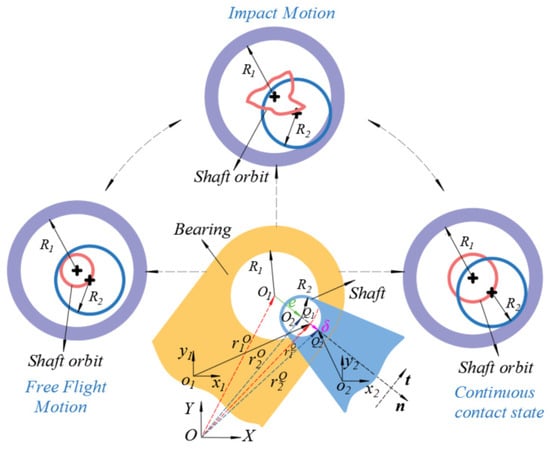
Figure 5.
Clearance model of rotating pair.
The magnitude of eccentricity value between the shaft and bearing is
The size of embedding depth at clearance can be written as
where is clearance size, .
The unit vector of the eccentricity vector between the bearing and the shaft is
Criteria for determining collisions between components in a rotating joint with clearance are as follows:
When the shaft collides with the bearing, judgment conditions are as follows:
The position vector of the collision point can be represented as
The velocity vector at the collision point is
where is the first derivative of the eccentric vector unit vector, .
The velocity components of the collision point of the bearing relative to the axis in the normal and tangential directions are
where the tangential vector t can be obtained by rotating n counterclockwise by 90°.
2.2.2. Collision Force Model of the Revolute Clearance Pair
The L-N model is widely applied in the normal collision force model at the clearance of the rotating pair, which can be written as
where KR is the stiffness coefficient, DR is the damping coefficient, and is the embedded depth velocity.
The stiffness coefficient and damping coefficient can be expressed as
where is the initial collision velocity; and represent Poisson’s ratio; and E1 and E2 represent elastic modulus.
Friction force at the revolute clearance also uses the modified Coulomb friction model, which is expressed in the same form as Equation (8).
3. Establishment of Beam Unit Model
3.1. Rigid Beam Unit
The reference point coordinate method is used to model the rigid beam element. Generalized coordinate of the rigid element can be written as
where xr and yr are the centroid coordinates, and θr is the rotation angle.
The mass matrix of the rigid beam element is
where mr and Jr represent the mass and moment of the inertia of the rigid beam element.
Gravity is simplified as a generalized force acting on the center of the mass of the element, which can be written as
The dynamic equation of the rigid element is
3.2. Flexible Beam Unit
The flexible element is modeled by using the absolute node coordinate method, and a one-dimensional two-node element is applied to divide the flexible element. The model of the flexible beam element is shown in Figure 6. The position vector of any point could be written as
where x is the local coordinates of the unit in the axial direction; S is the global shape function; and is the generalized coordinate, which can be expressed as
where and are position vectors of nodes i and j, and are slope vectors in the tangential direction of the axis of the flexible element.
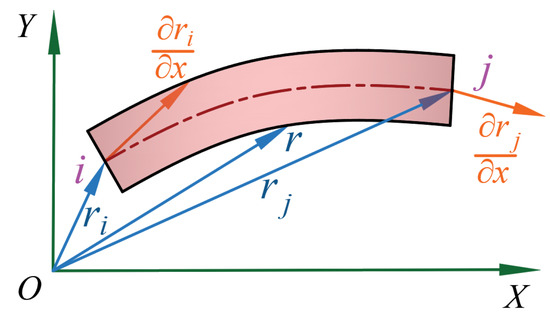
Figure 6.
Model of flexible beam element.
The shape function of the flexible element is expressed as
where represents a 2 × 2 unit matrix; ; ; ; ; and ; l is the length of the flexible beam element.
The absolute velocity vector can be obtained by taking the derivative of Equation (26) over time, . The kinetic energy of the flexible element is
where ρ is density; is the constant mass matrix of the flexible element, which can be written as
The elastic force of a flexible element is expressed as
where , , and are the total strain energy, bending strain energy, and axial tensile strain energy of the flexible element, respectively, for isotropic materials; and can be written as
where E, , , Aa, and are Young’s modulus, curvature of the beam element, moment of inertia of the cross-section, cross-sectional area of the beam unit, and strain of the beam element, respectively.
Bending elastic force and axial elastic force are expressed as
Bending stiffness and axial stiffness are expressed as
The strain could be simply written as
The generalized force of a flexible element is
The dynamic equation of a flexible beam element is
4. Rigid–Flexible Coupling Dynamic Modeling of a Mechanism with Revolute Clearance and Translational Clearance
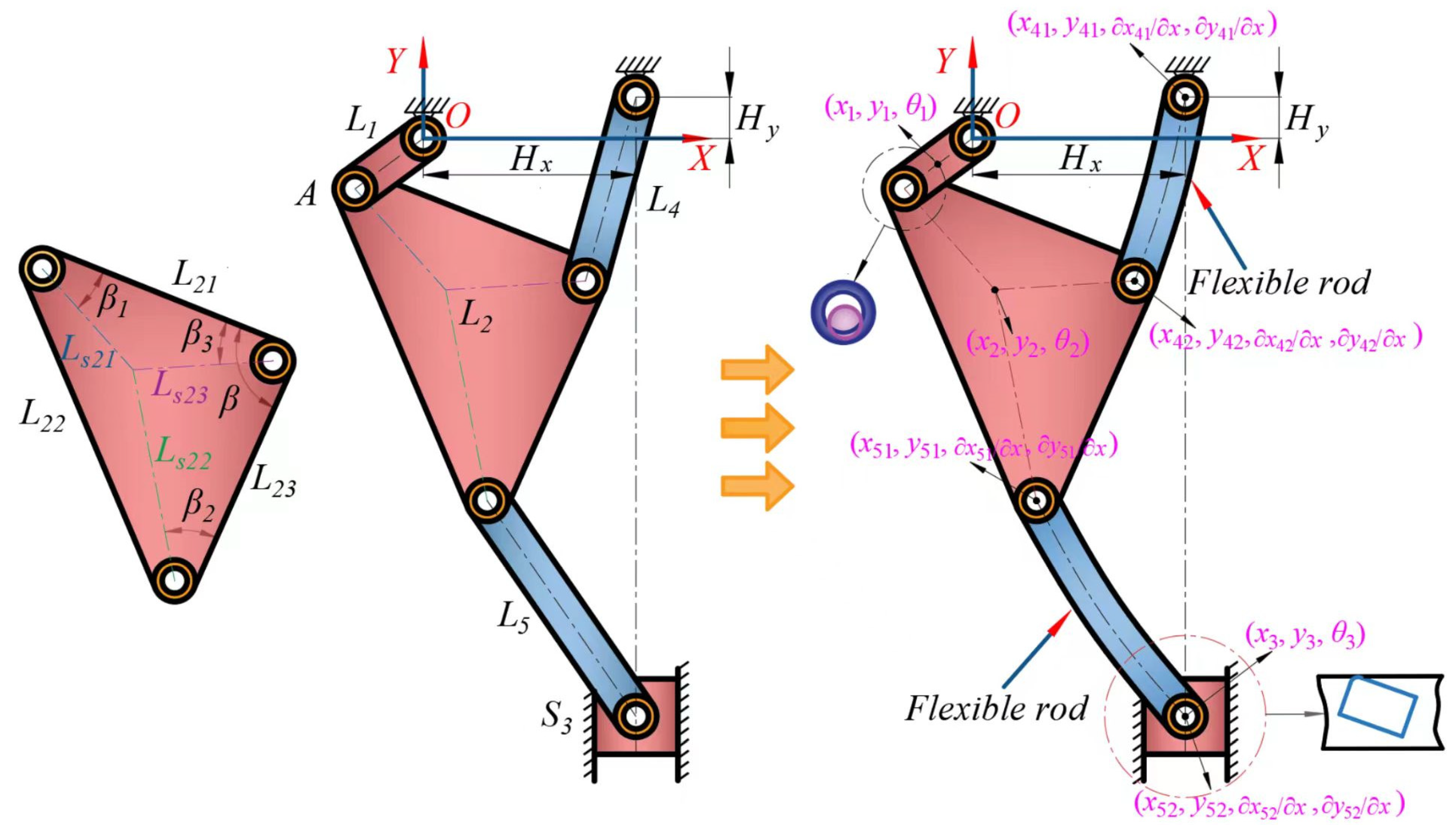
A schematic diagram of a multilink press mechanism is shown in Figure 7, which includes crank 1, triangle plate 3, connecting rod 2, connecting rod 4, and slider. Because component 3 is a triangular plate structure that is not easily deformed during the operation of the mechanism, it is considered that link 2 and link 4 in the mechanism are flexible components, while the other components are regarded as rigid components. The revolute clearance pair at the driving component and translational clearance between the slider and guide can directly affect the driving torque and motion characteristics of the slider. Therefore, this paper focuses on the comprehensive coupling effect of rotating pair A clearance and translational clearance B on the mechanism.
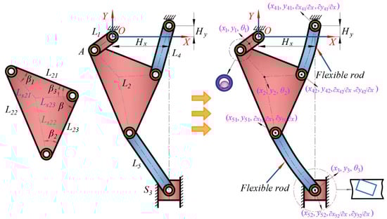
Figure 7.
Schematic diagram of multilink press mechanism.
The generalized coordinates of components can be written as
The generalized coordinates of a system considering compound clearances are
where is the generalized coordinate of the system’s rigid components, , and is the generalized coordinate of flexible components, .
Each kinematic pair can introduce two constraint equations. Considering the presence of the clearance at rotating pair A, as well as clearance B at the translational pair, the constraints on rotating pair A and the translational pair B fail due to the presence of clearances. At this point, the constraint equation of system is
The velocity constraint equation could be written as
where is the Jacobian matrix, .
The Jacobian matrix can be represented as
where and are derivative of the constraint equation with respect to generalized coordinates of rigid components and flexible components, respectively. , .
The acceleration constraint equation can be written as
where , .
The dynamic model of the system could be represented as
where and are the mass matrix and external force of rigid components for the whole system, λ is a Lagrange multiplier, and , , and are the mass matrix, external force, and elastic force of flexible rods for the whole system, respectively.
Baumgarte proposed an algorithm that combines displacement and velocity constraints into an acceleration constraint equation to improve the stability of the solution.
where α and β are Baumgarte feedback parameters.
5. Dynamic Response Analysis and Chaos Identification
5.1. Solution of Dynamic Equations for Mechanisms with Compound Clearances
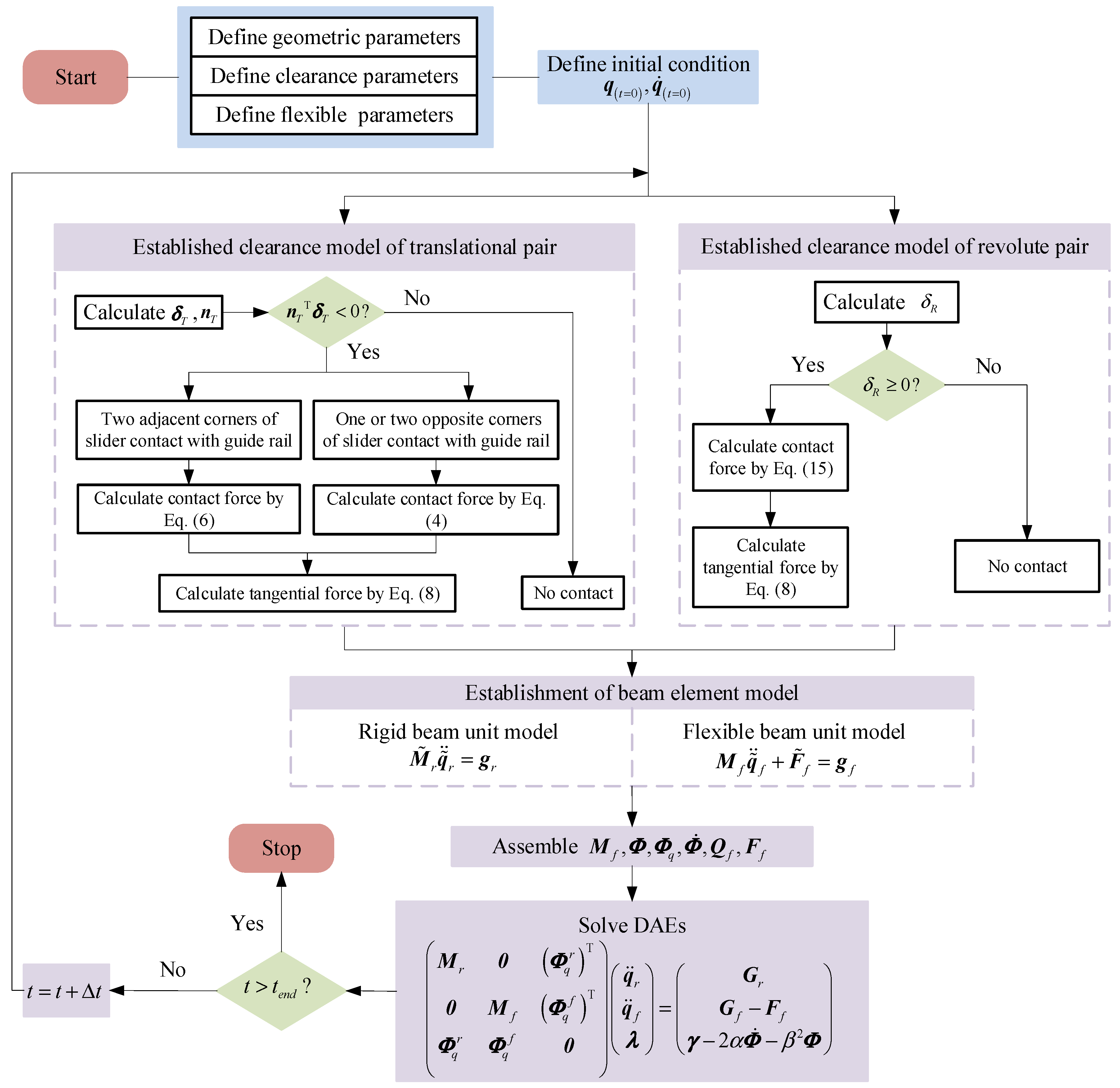
A flowchart for solving the dynamic equation with a flexible rod and compound clearances is shown in Figure 8.
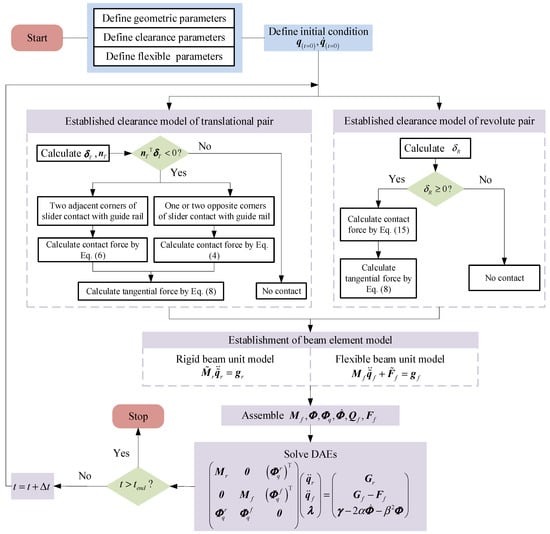
Figure 8.
Flowchart for solving the dynamic equation with a flexible rod and compound clearances.
5.2. Simulation Parameters
The rod length parameters of the mechanism through kinematic optimization in the early stage are obtained, and a three-dimensional model of the six-bar mechanism from SOLIDWORKS is established. Then, the SOLIDWORKS model is imported into ADAMS 2020 software for the establishment of a virtual prototype model. And the mass, moment of inertia of the rod, and cross-sectional area from the ADAMS virtual prototype model are measured; the material of the component is defined as iron. Geometric parameters of the mechanism are displayed in Table 1. Parameters of clearance and the flexible rod are displaced in Table 2.

Table 1.
Geometric parameters of the mechanism.
Table 2.
Parameters of clearance and flexible rod.
5.3. Chaos Identification
Translational and revolute pairs are common motion pairs in mechanisms, and the clearances at the motion pair can cause collisions and wear between components of motion pair, resulting in uncertainty in the motion of the mechanism. Elastic deformation of the component will cause deformation and accelerate the shaking of the mechanism. For the six-bar mechanism studied in this article, the coupling effect of clearance between rotating joints, clearance between translational pairs, and the elastic deformation of the rods are important factors that cause chaos, leading to a decrease in its stability. Therefore, it is very important to perform chaos identification on mechanisms with compound clearances and flexible components.
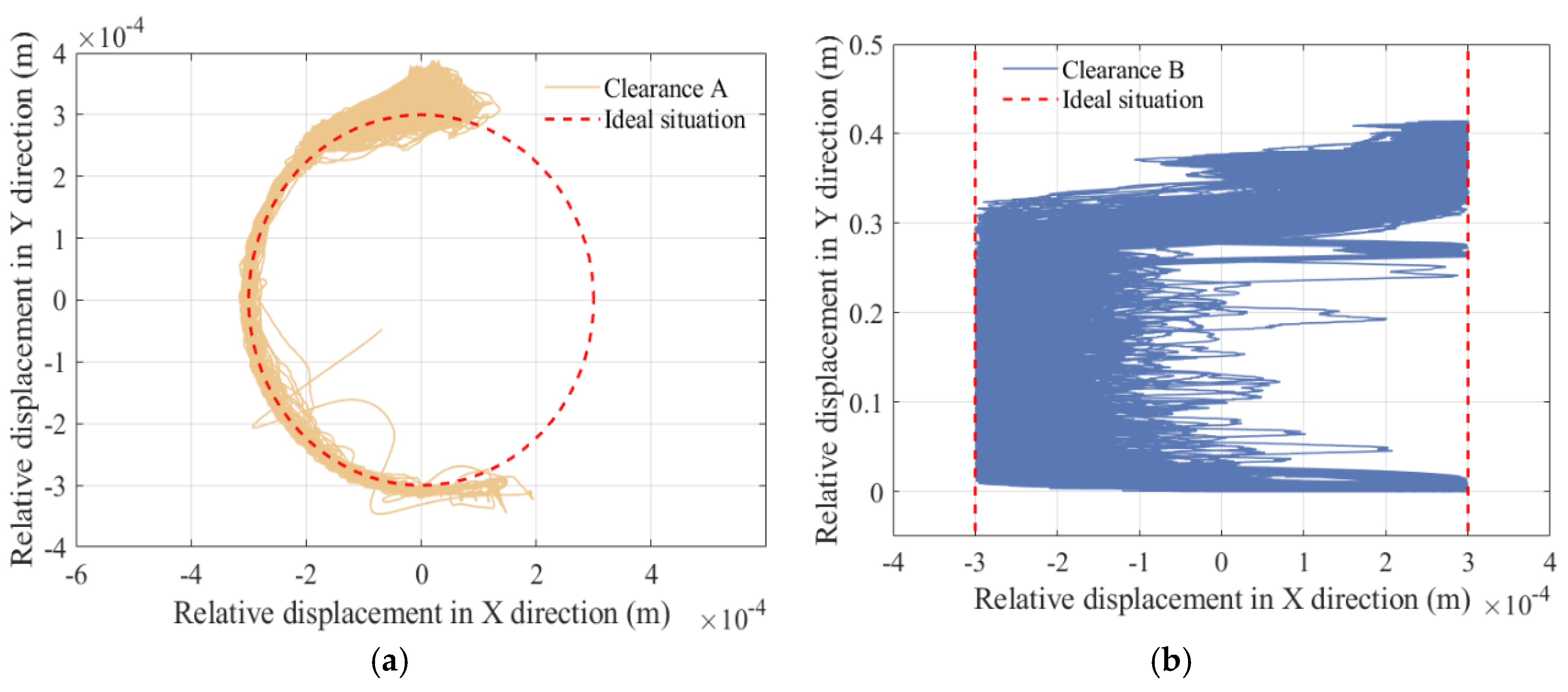
We selected the following parameters for simulation analysis: the driving speed of the slider 1 is 150 rpm, the friction coefficient is 0.15, and the clearance value of clearance joints B, C, and F are all set as 0.3 mm. When the mechanism operates at 100 cycles, chaos identification of the mechanism’s motion is performed based on the data from these 100 cycles. Center trajectories at the clearance are shown in Figure 9.
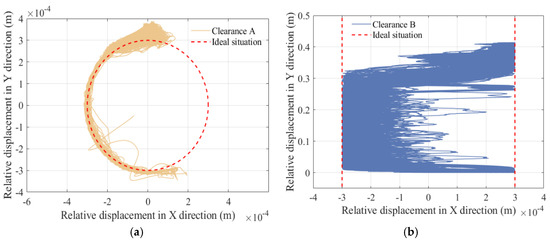
Figure 9.
Center trajectories at the clearance. (a) Revolute clearance A. (b) Translational clearance B.
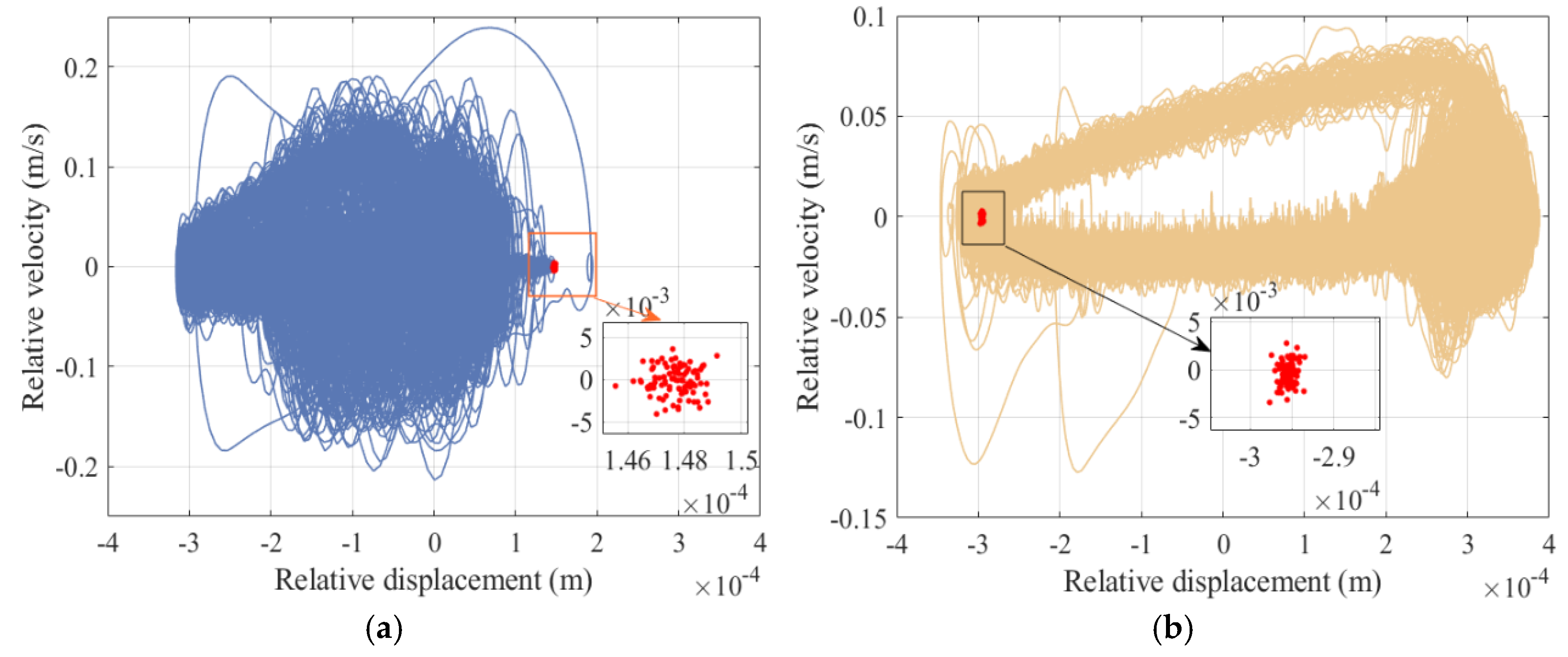
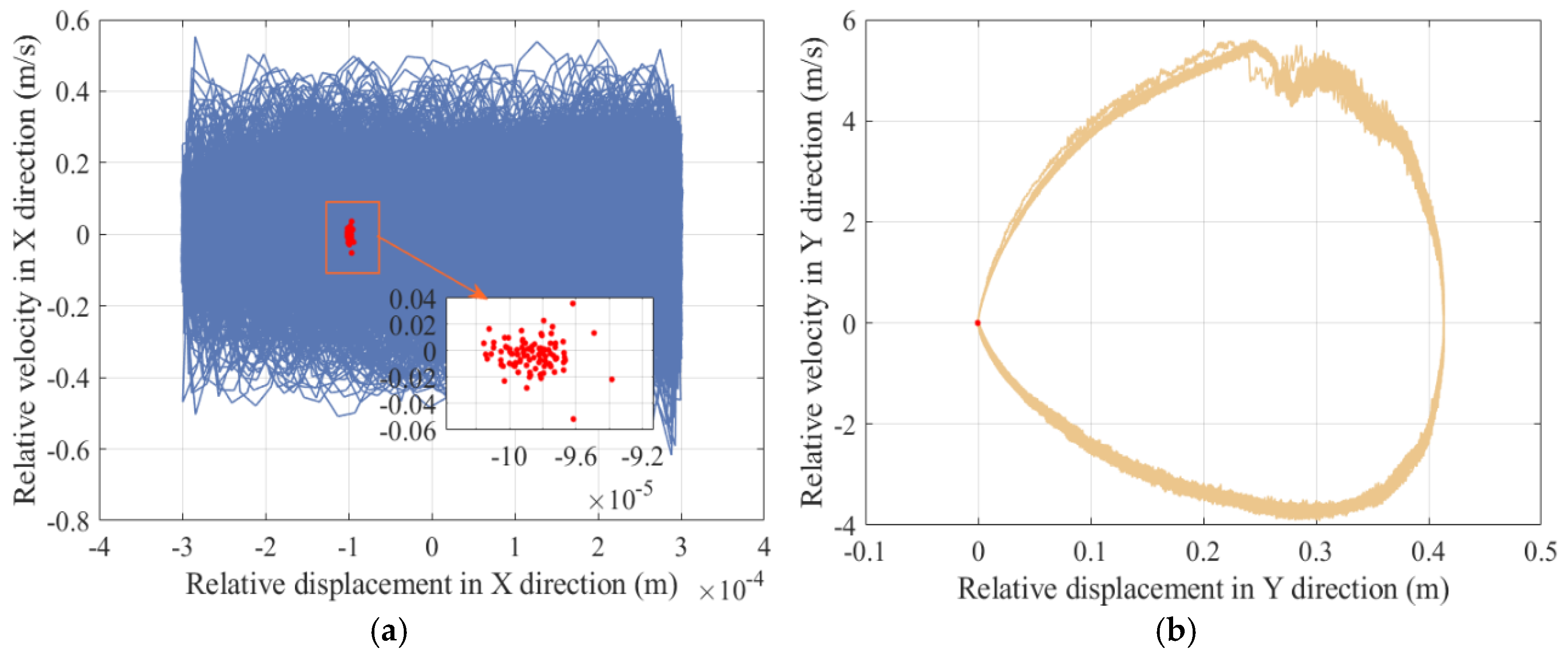
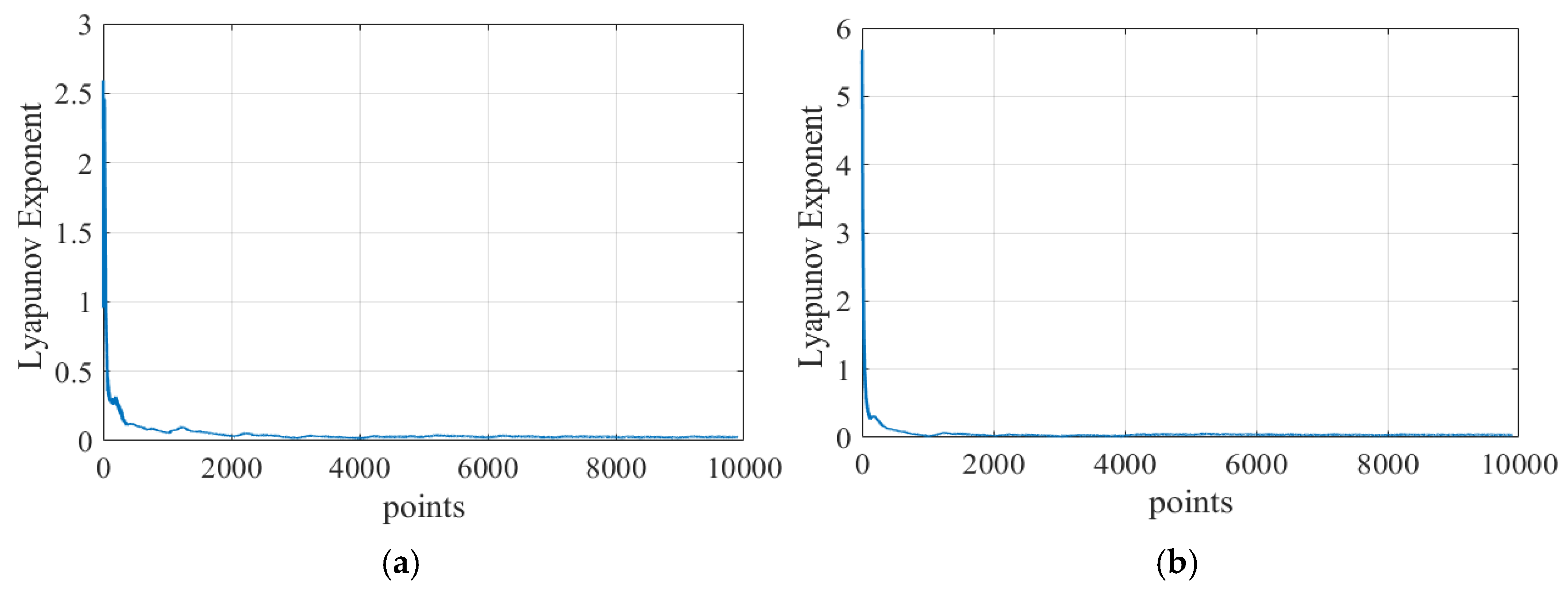
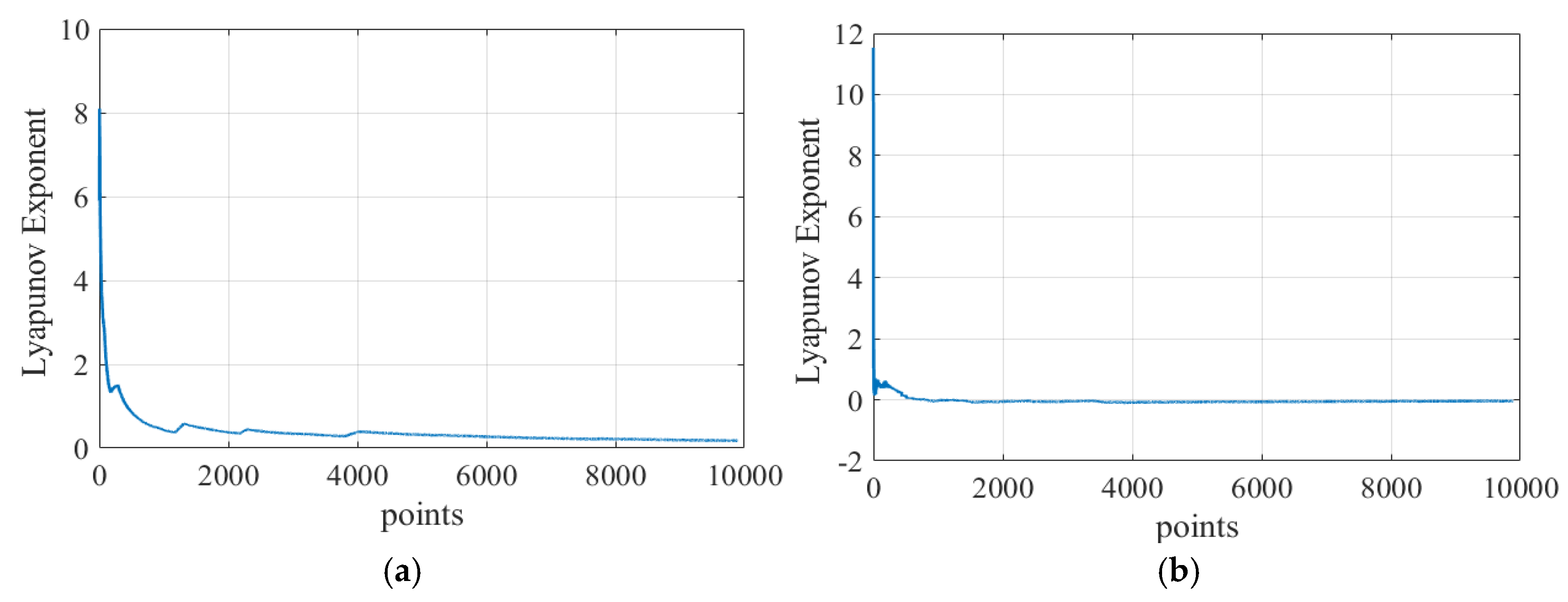
A phase diagram and Poincaré diagram at revolute clearance A and translational clearance B are shown in Figure 10 and Figure 11, respectively. Lyapunov exponent diagrams at revolute clearance A and translational clearance B are displayed in Figure 12 and Figure 13. When the maximum Lyapunov exponent is greater than zero, the mechanism is in a chaotic state, and when the maximum Lyapunov exponent is less than zero, the mechanism is in a periodic state. Maximum Lyapunov exponents at the clearances of revolute joint A (X direction and Y direction) and translational pair B (X direction and Y direction) are 0.0521, 0.0573, 0.3915, and −0.0287, respectively.
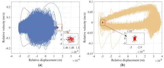
Figure 10.
Phase diagram and Poincaré diagram at revolute clearance A (a) in the X direction and (b) in the Y direction.

Figure 11.
Phase diagram and Poincaré diagram at translational clearance B (a) in the X direction and (b) in the Y direction.
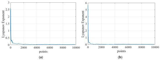
Figure 12.
Lyapunov exponent diagram at revolute clearance A (a) in the X direction and (b) in the Y direction.
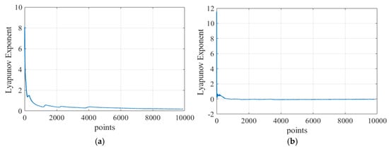
Figure 13.
Lyapunov exponent diagram at translational clearance B (a) in the X direction and (b) in the Y direction.
The maximum Lyapunov exponent at the clearances, in descending order, are translational clearance (X direction), revolute clearance (Y direction), revolute clearance (X direction), and translational clearance (Y direction). From this, it can be inferred that translational clearance (X direction) has the highest degree of chaos, while translational clearance (Y direction) has the lowest degree of chaos. Revolute pair A (X direction and Y direction) and translational pair B (X direction) are in the chaotic state, and translational pair B (Y direction) is in periodic motion.
5.4. Influence of Clearance Values on the Dynamic Response
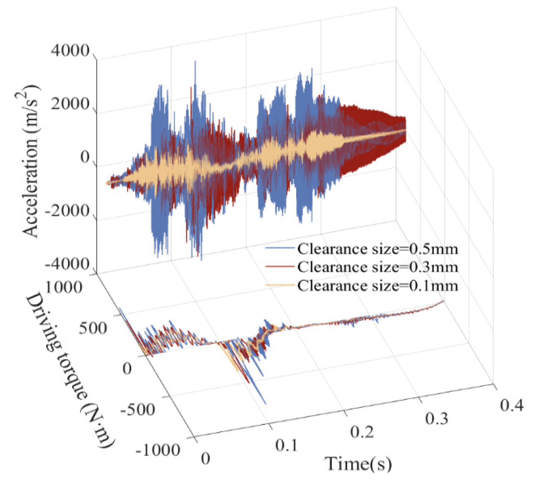
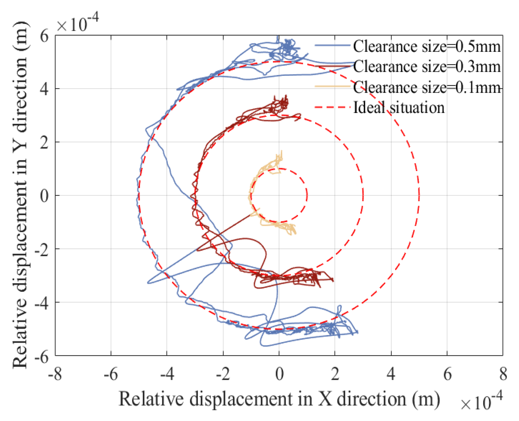
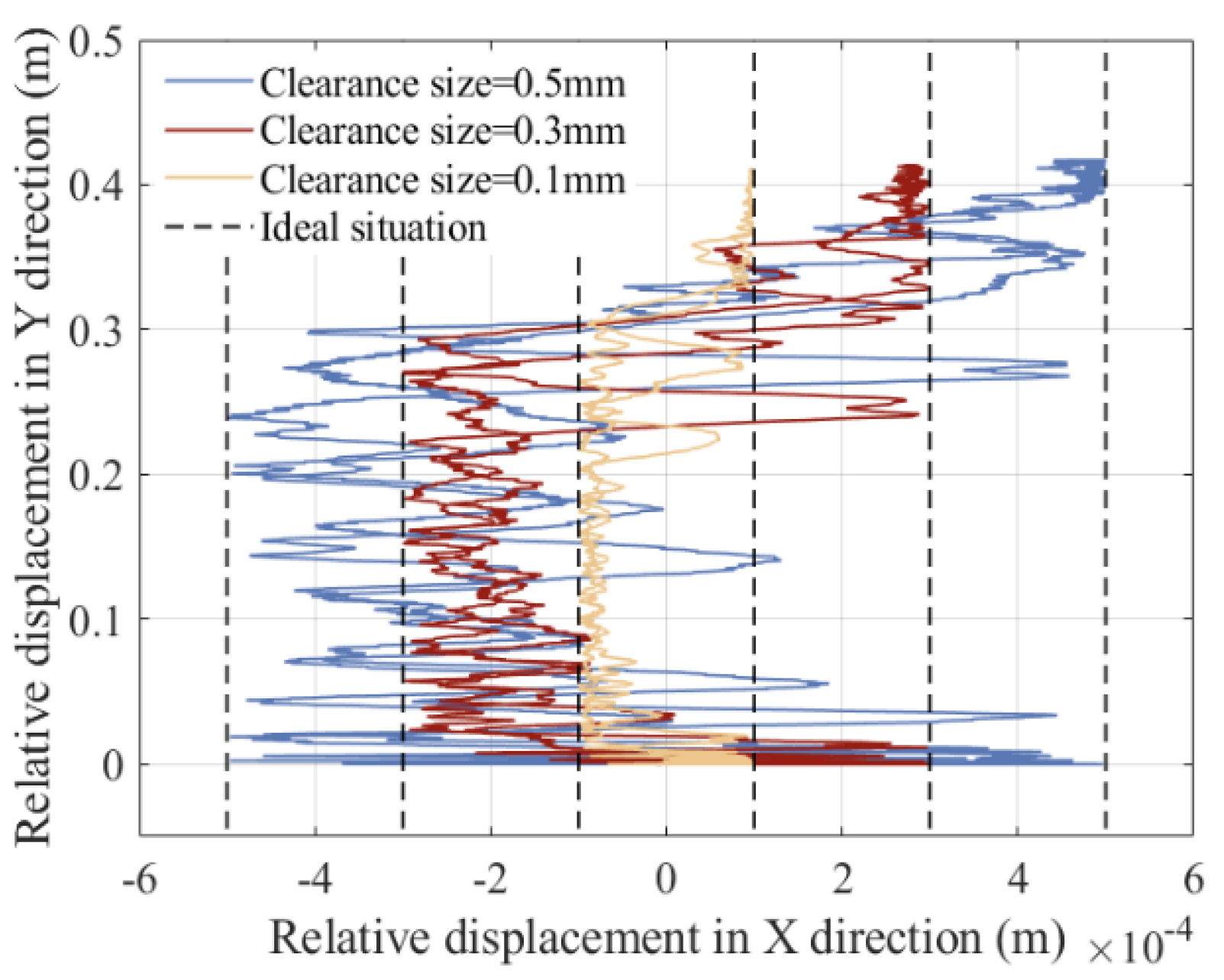
This section analyzes the influence of clearance sizes on the dynamic response of a rigid–flexible coupling six-bar mechanism with compound clearances. It is considered that clearance exists simultaneously at revolute pair A, as well as at translational pair B, and it is assumed that the three clearances have the same clearance value size. Three different clearance sizes are selected to analyze the impact of different clearance values on the mechanism, namely 0.1 mm, 0.3 mm, and 0.5 mm. The friction coefficient is set to 0.15, and the driving speed of slider 1 is set to 150 rpm. The displacement and velocity of the slider, acceleration of the slider, driving torque of crank, contact force of revolute clearance A, trajectory of revolute clearance A, contact force of revolute clearance B, and trajectory of revolute clearance B are shown in Figure 14, Figure 15, Figure 16, Figure 17, Figure 18 and Figure 19.
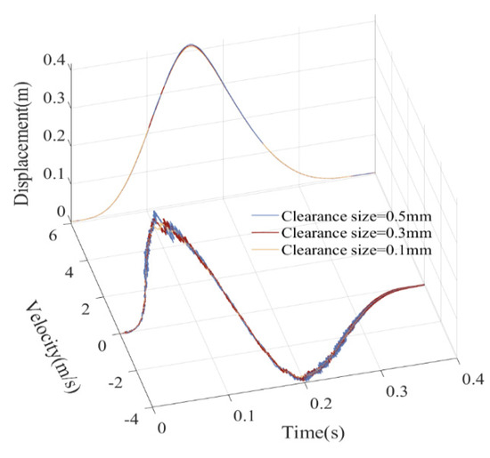
Figure 14.
Displacement and velocity of the slider.

Figure 15.
Acceleration of the slider and driving torque of crank.
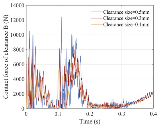
Figure 16.
Contact force of revolute clearance A.
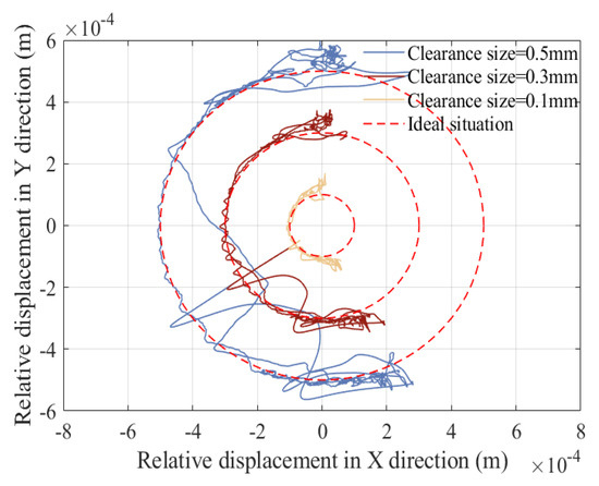
Figure 17.
Trajectory of revolute clearance A.
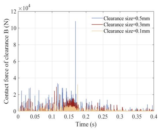
Figure 18.
Contact force of translational pair B.
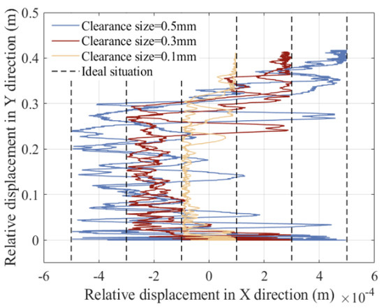
Figure 19.
Trajectory of translational pair B.
From the displacement curve, clearance size has a relatively small impact on displacement, and the curve fluctuations are not significant. The speed curve fluctuates to a certain extent with the increase in clearance size, but there is no significant vibration peak. The acceleration, driving torque, and collision force curves at the clearances have significant vibration peaks and intense vibration frequencies, and as the clearance value increases, the response peak also increases. From the center trajectories of clearance A, the collision of clearance A in the revolute pair is mainly concentrated on the upper and lower ends. From the center trajectory of translational pair B, collision and contact between the guide rail and slider are mainly concentrated on the left guide rail, and as clearance size increases, the motion trajectory of the slider becomes more chaotic.
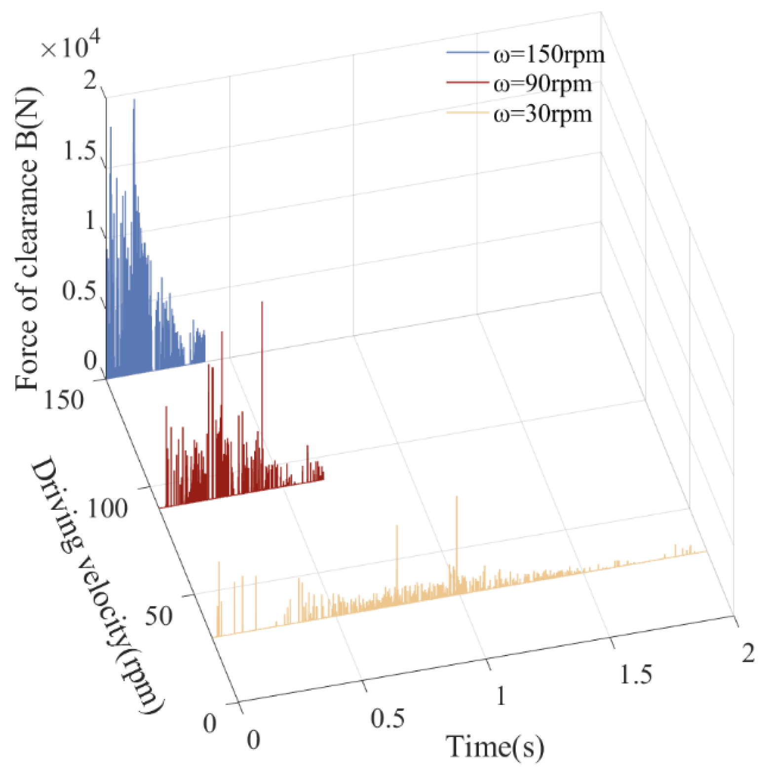
5.5. The Influence of Driving Velocities on Dynamic Response
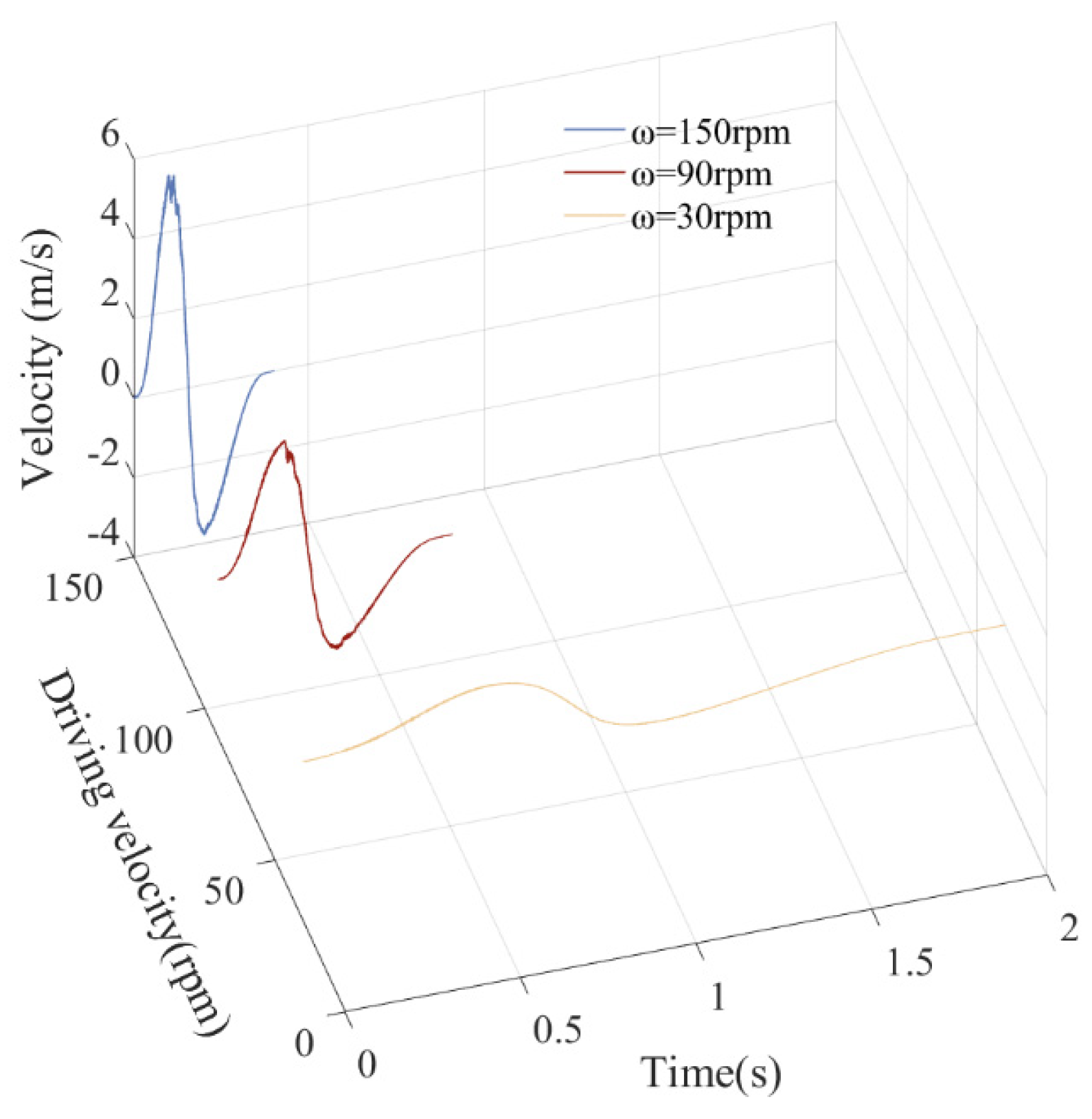
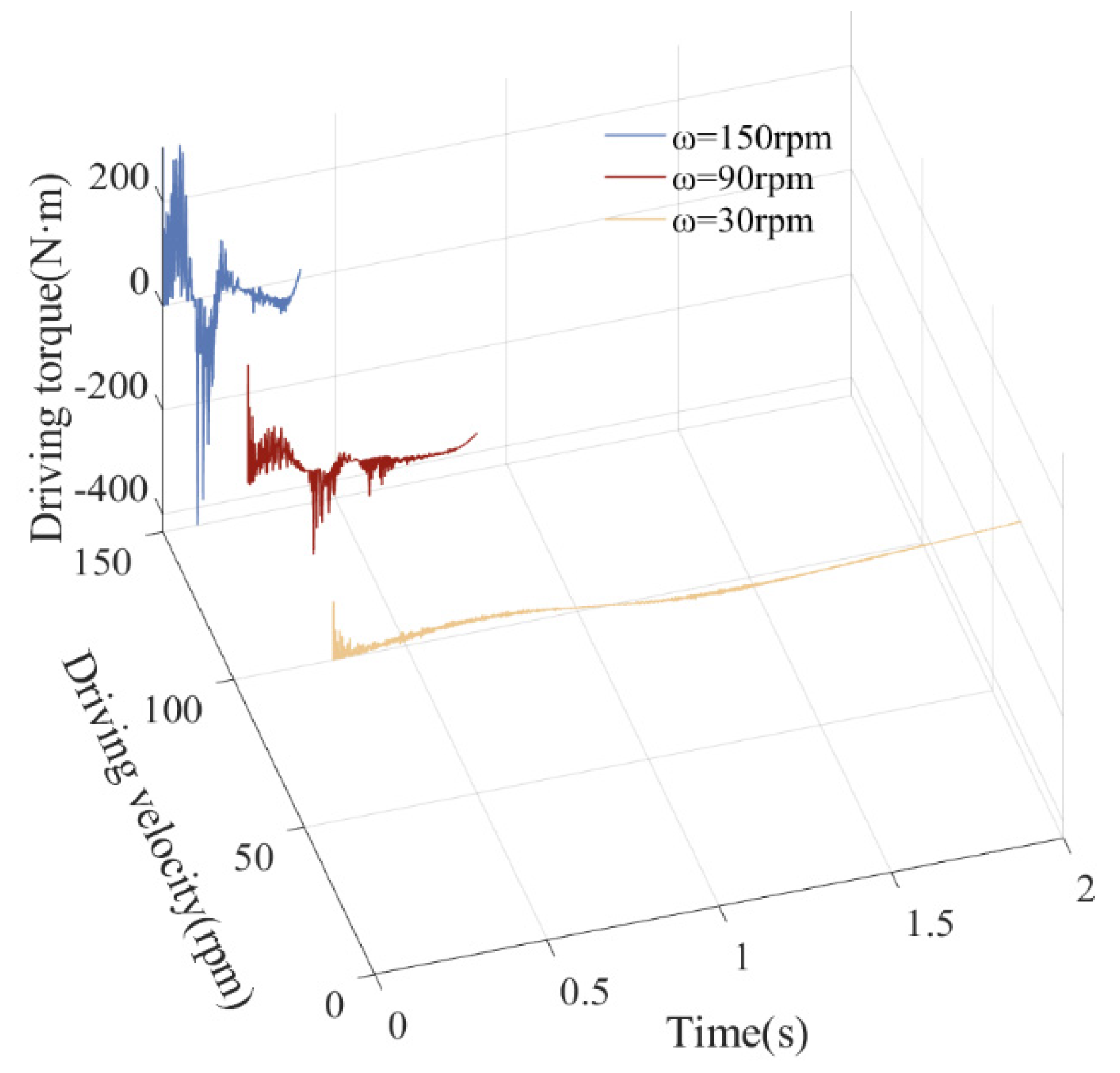
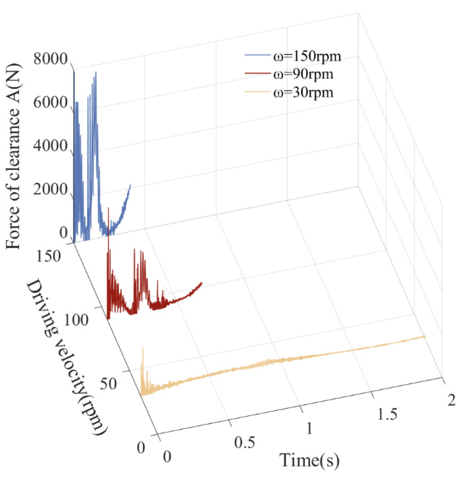
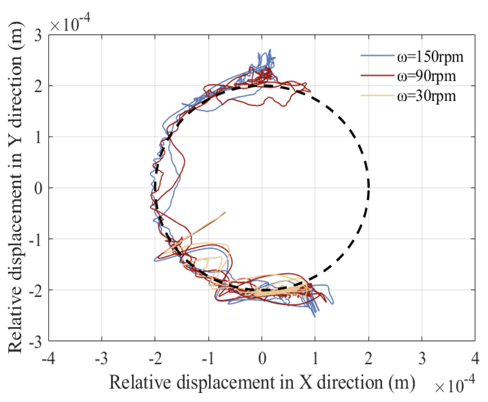
This section analyzes the influence of driving speed on the dynamic response of a rigid–flexible coupling six-bar mechanism with compound clearances. Three different driving speeds of slider 1 are selected to analyze the impact of driving speed on the mechanism, namely 30 rpm, 90 rpm, and 150 rpm. The friction coefficient is set to 0.15, and clearance values of revolute pair clearance A and translational pair clearance B are both 0.2 mm. The displacement of the slider, velocity of the slider, acceleration of the slider, driving torque of crank, contact force of revolute clearance A, trajectory of revolute clearance A, contact force of translational pair B, and trajectory of translational pair B are displayed in Figure 20, Figure 21, Figure 22, Figure 23, Figure 24, Figure 25, Figure 26 and Figure 27.
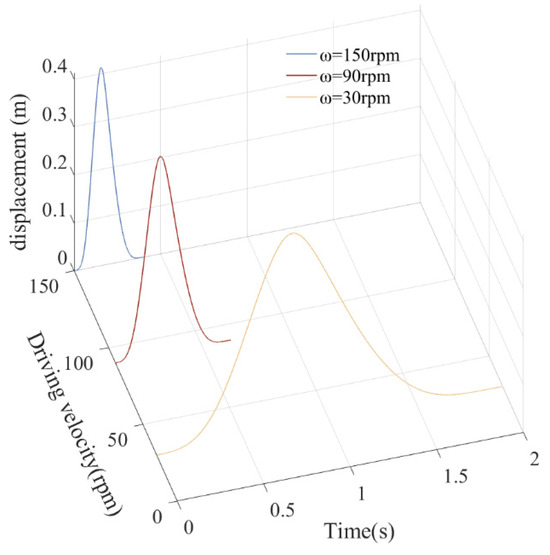
Figure 20.
Displacement of slider.
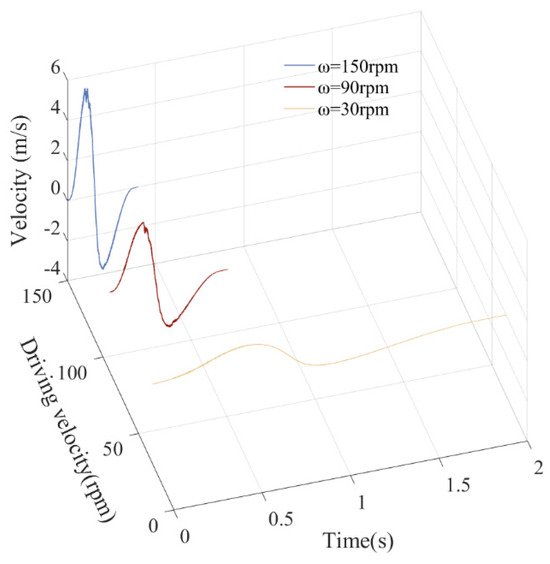
Figure 21.
Velocity of slider.
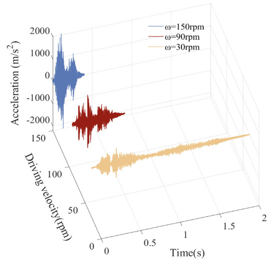
Figure 22.
Acceleration of slider.
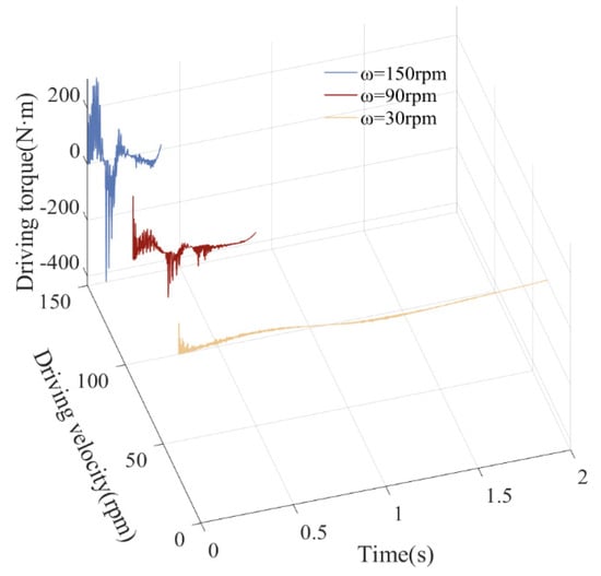
Figure 23.
Driving torque of crank.
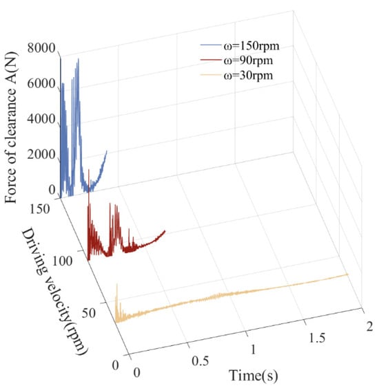
Figure 24.
Contact force of revolute clearance A.
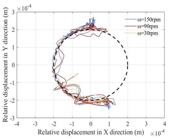
Figure 25.
Trajectory of revolute clearance A.
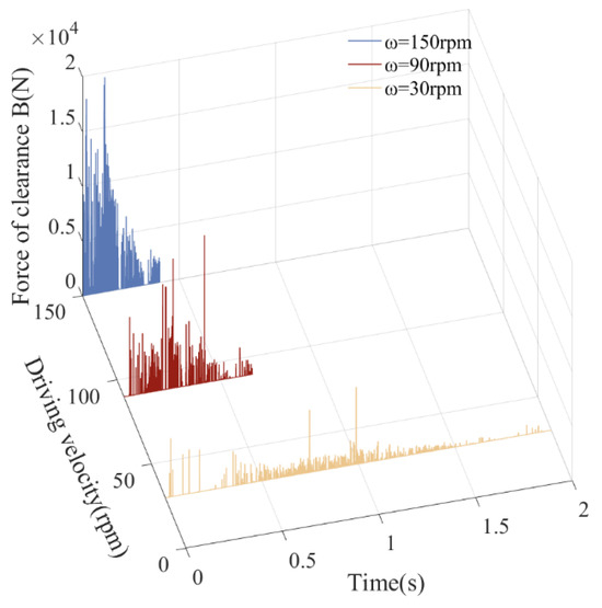
Figure 26.
Contact force of translational pair B.
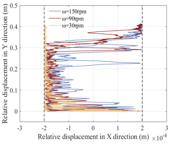
Figure 27.
Trajectory of translational pair B.
From the displacement curve, there is no significant fluctuation or vibration in the displacement curve, and the effect of changes in driving speed on displacement is relatively small. From curves of speed, acceleration, driving torque, and collision force at clearance, as driving speed increases, peak dynamic response also increases, and the mechanism becomes very unstable. Due to the faster running speed of the mechanism, the impact of revolute joint A and the impact of translational pair B become more severe, the fluctuation in the response is more significant, and the peak value also increases. The center trajectory of rotating clearance and translational clearance shows that when running speed increases from 30 rpm to 90 rpm, and then to 150 rpm, the degree of confusion in the trajectory increases, and the number of collisions between elements of clearance pairs increases.
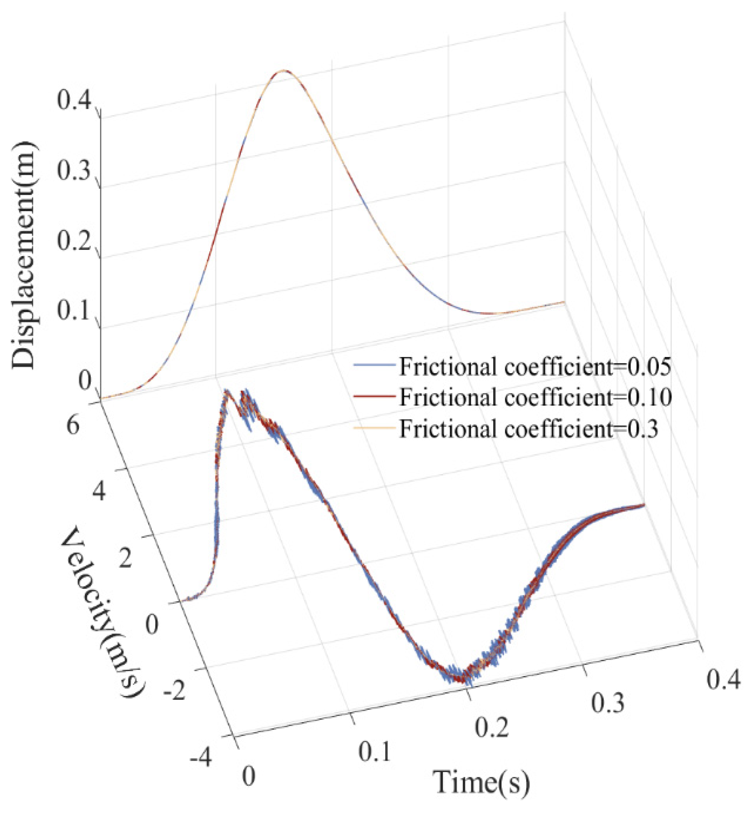
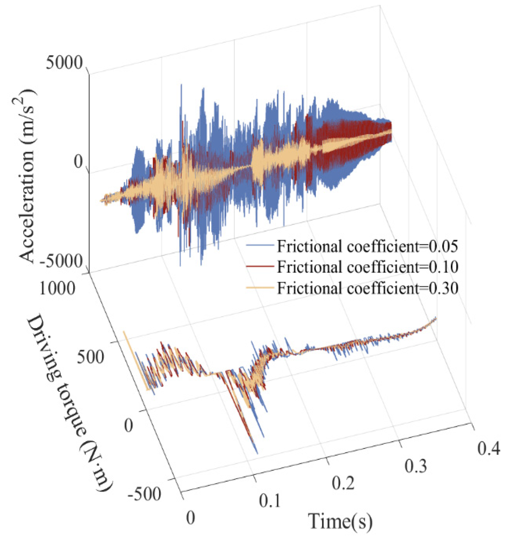
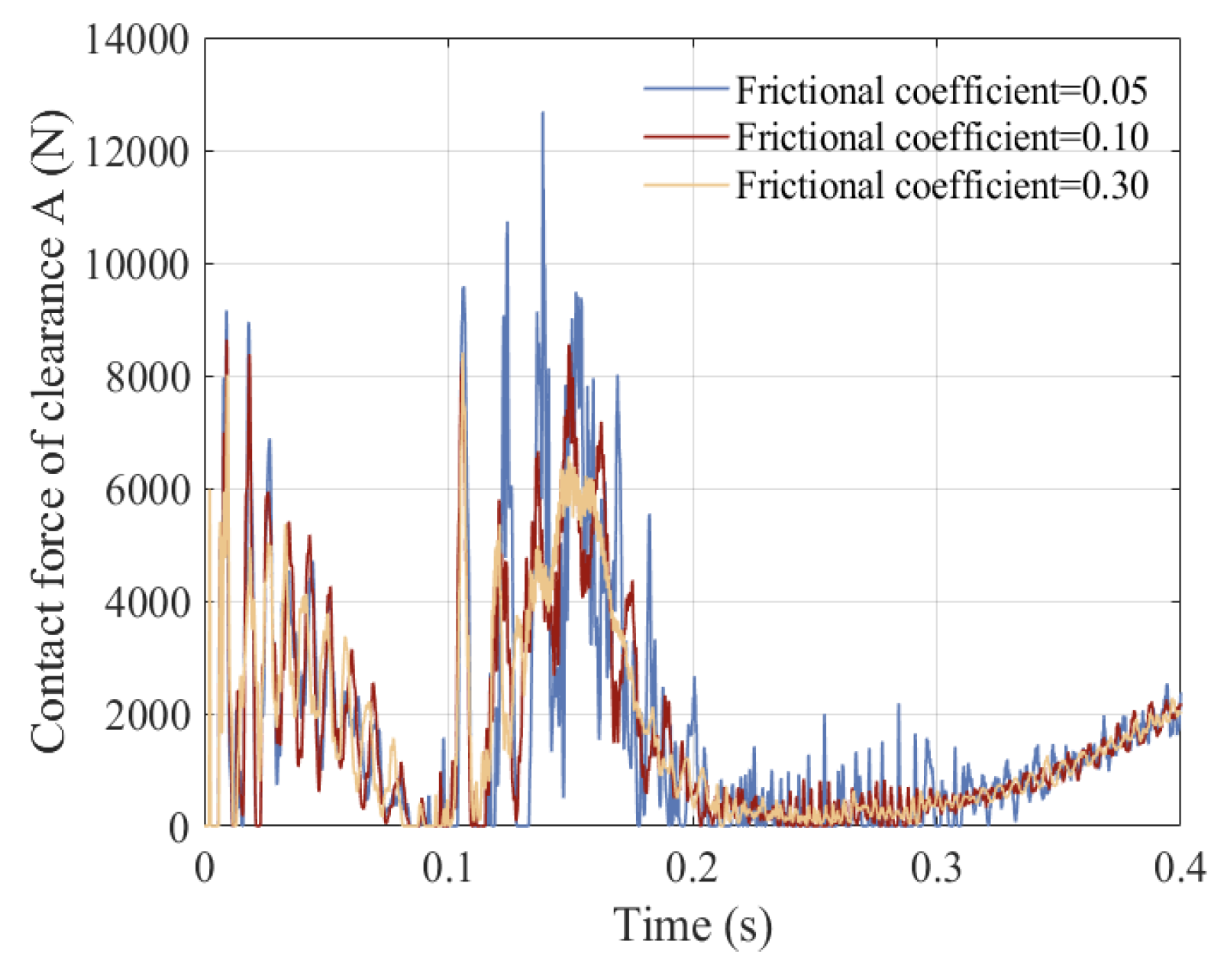
5.6. Influence of Frictional Coefficients on the Dynamic Response
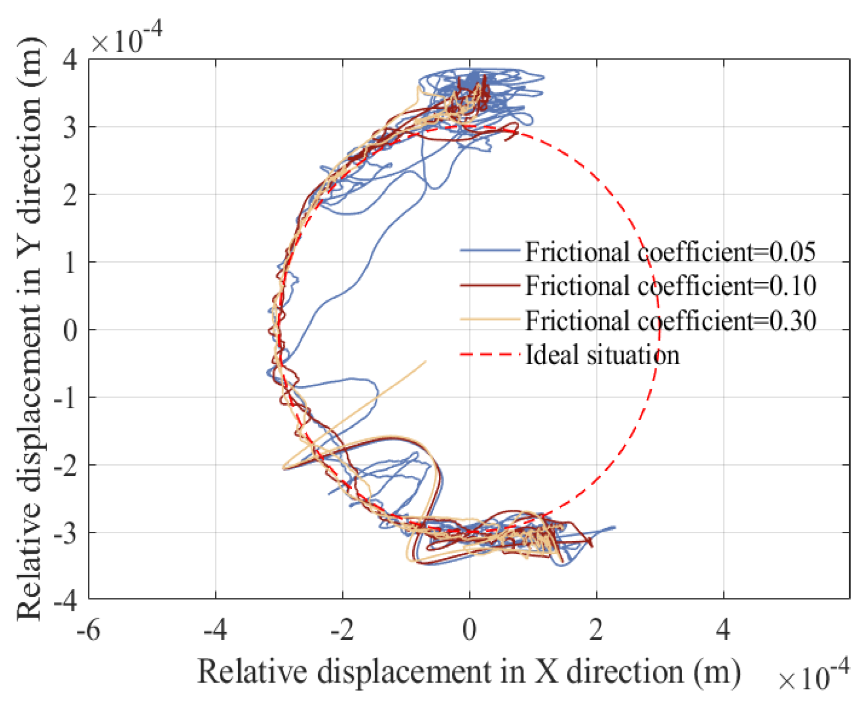
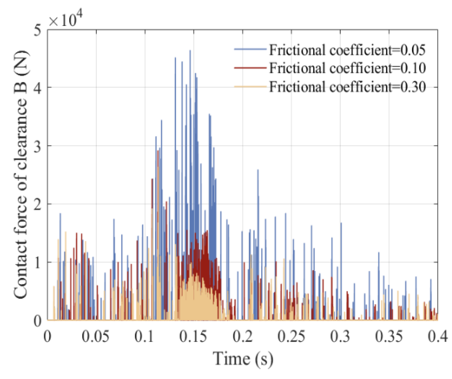
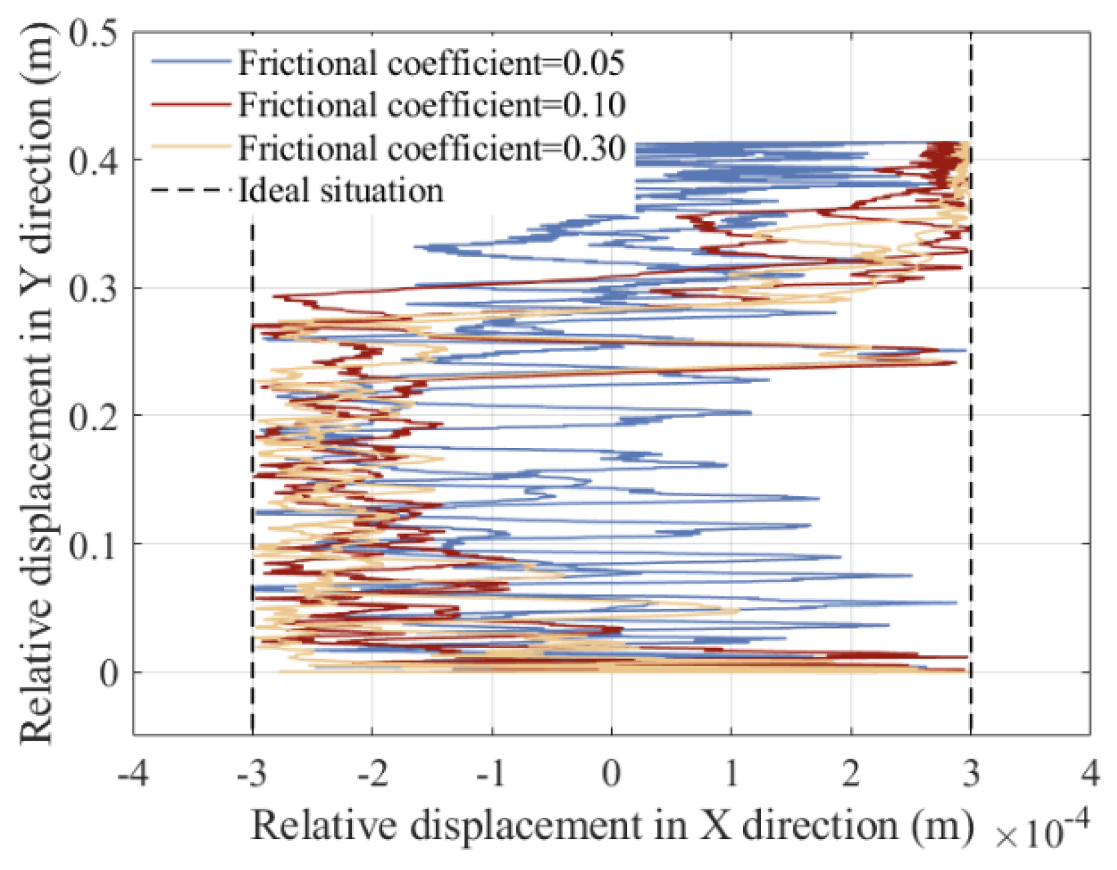
Due to the presence of nonlinear factors such as clearance between revolute pairs, clearance between translational pairs, and elastic deformation, changes in the frictional coefficients of a clearance pair can also affect its operational stability. So, in order to better describe the impact of frictional coefficients on the dynamics, displacement, and velocity of the slider, the acceleration of the slider and driving torque of crank, the contact force of revolute clearance A, the trajectory of revolute clearance A, the contact force of revolute clearance B, and the trajectory of revolute clearance B changing by frictional coefficient are studied, as shown in Figure 28, Figure 29, Figure 30, Figure 31, Figure 32 and Figure 33. The three selected friction coefficients are 0.05, 0.1, and 0.3. The operating speed of the mechanism is 150 rpm, and clearance values of the revolute pair and translational pair are 0.3 mm.
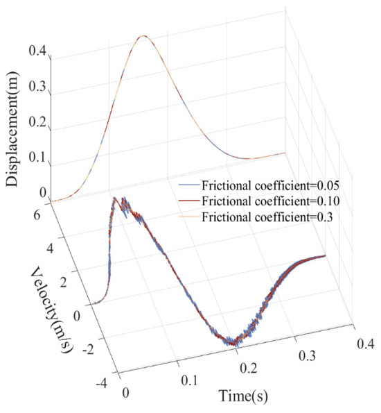
Figure 28.
Displacement and velocity of slider.

Figure 29.
Acceleration of slider and driving torque of crank.
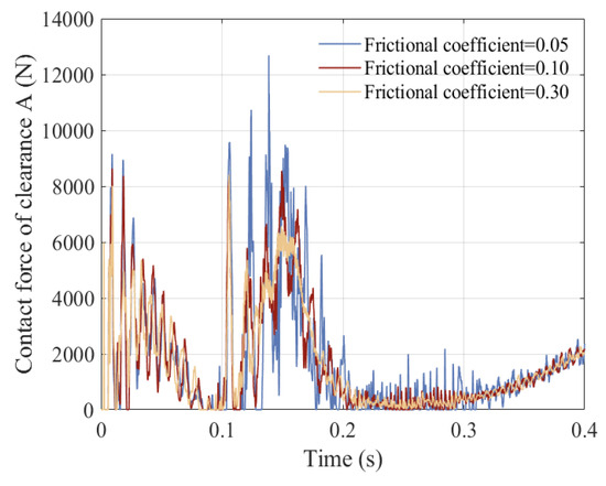
Figure 30.
Contact force of revolute clearance A.
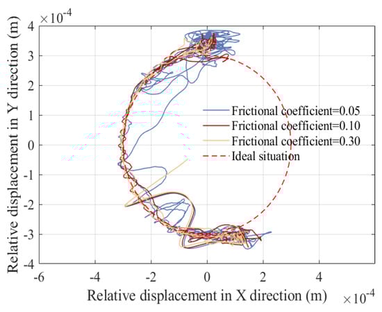
Figure 31.
Trajectory of revolute clearance A.
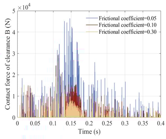
Figure 32.
Contact force of translational pair B.

Figure 33.
Trajectory of translational pair B.
Friction has a significant impact on the dynamic characteristics of a mechanism. Friction converts the mechanical energy of a system into thermal energy, causing the energy of the system to gradually dissipate, thereby changing vibration characteristics. This energy loss has a significant impact on dynamic characteristics. Increasing the friction coefficient will further increase the frictional force, causing an increase in vibration damping and a gradual decrease in amplitude, thereby reducing the system’s output power and increasing its heat loss. According to the dynamic response diagram (Figure 28, Figure 29, Figure 30, Figure 31, Figure 32 and Figure 33), as the friction coefficient increases, vibration frequency and the amplitude of the mechanism’s dynamic weaken, and the mechanism gradually exhibits a stable motion trend.
5.7. Comparison of Dynamic Response Between Rigid Mechanisms with Clearance and Rigid–Flexible Coupling Mechanisms with Clearance
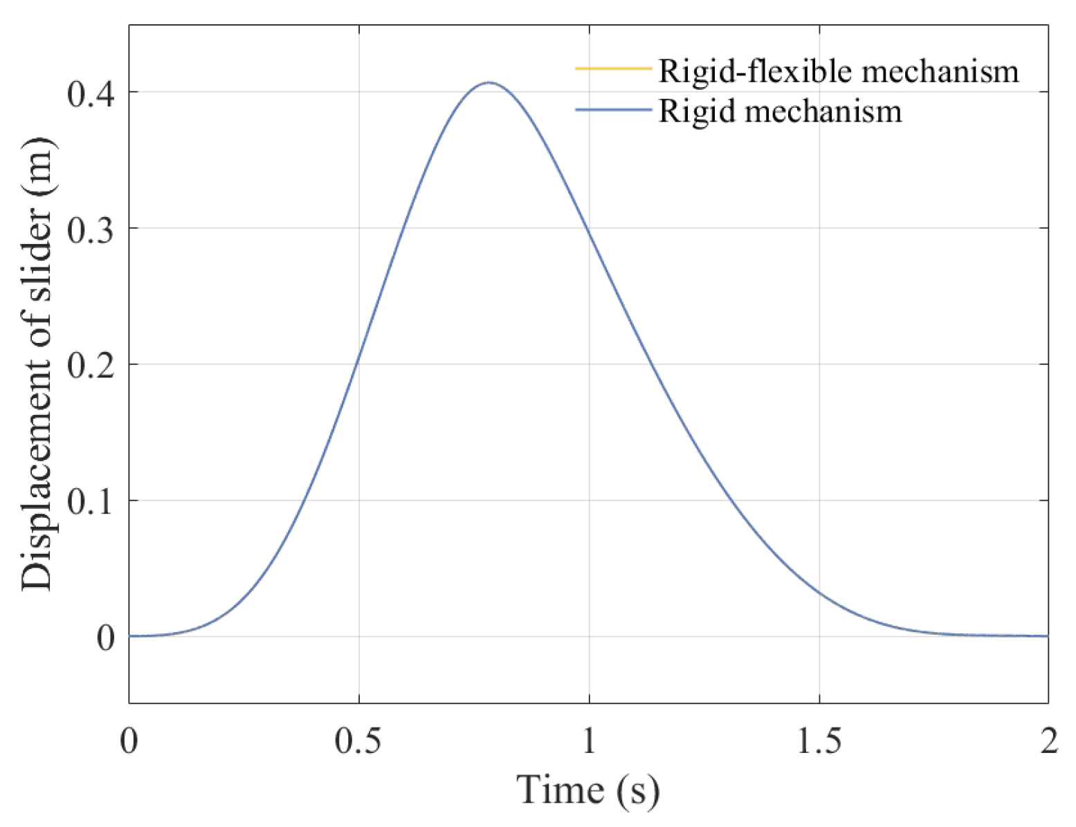
The focus of this study is to simultaneously consider the coupling effects of rotating pair clearance, moving pair clearance, and component flexibility on the mechanism. Many studies have overlooked the influence of component flexibility. Therefore, this article adds a comparison of displacement, velocity, acceleration, and center trajectory between rigid mechanisms with clearance and rigid–flexible coupling mechanisms with clearance, as shown in Figure 34, Figure 35, Figure 36, Figure 37, Figure 38, and Figure 39, respectively.
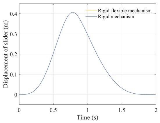
Figure 34.
Displacement of slider.
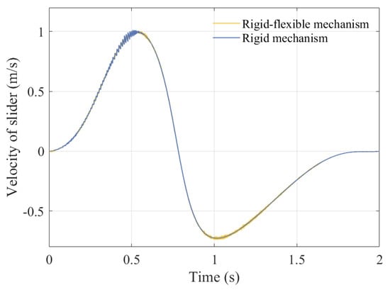
Figure 35.
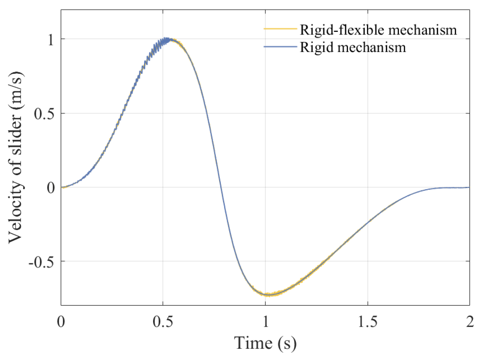
Velocity of slider.

Figure 36.
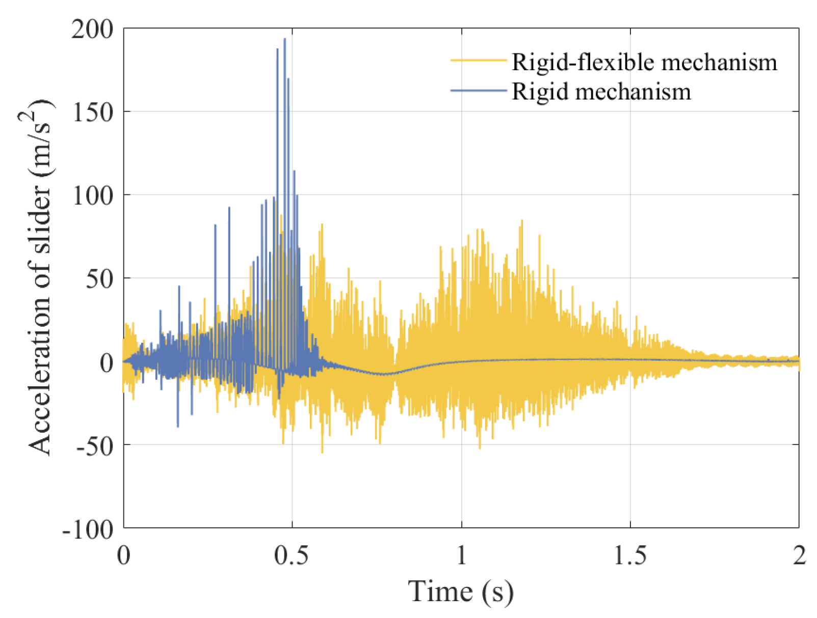
Acceleration of slider.
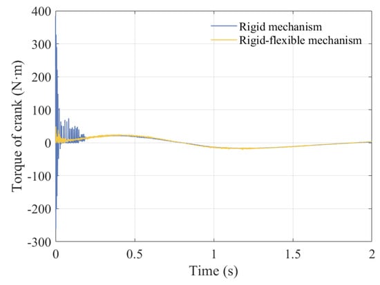
Figure 37.
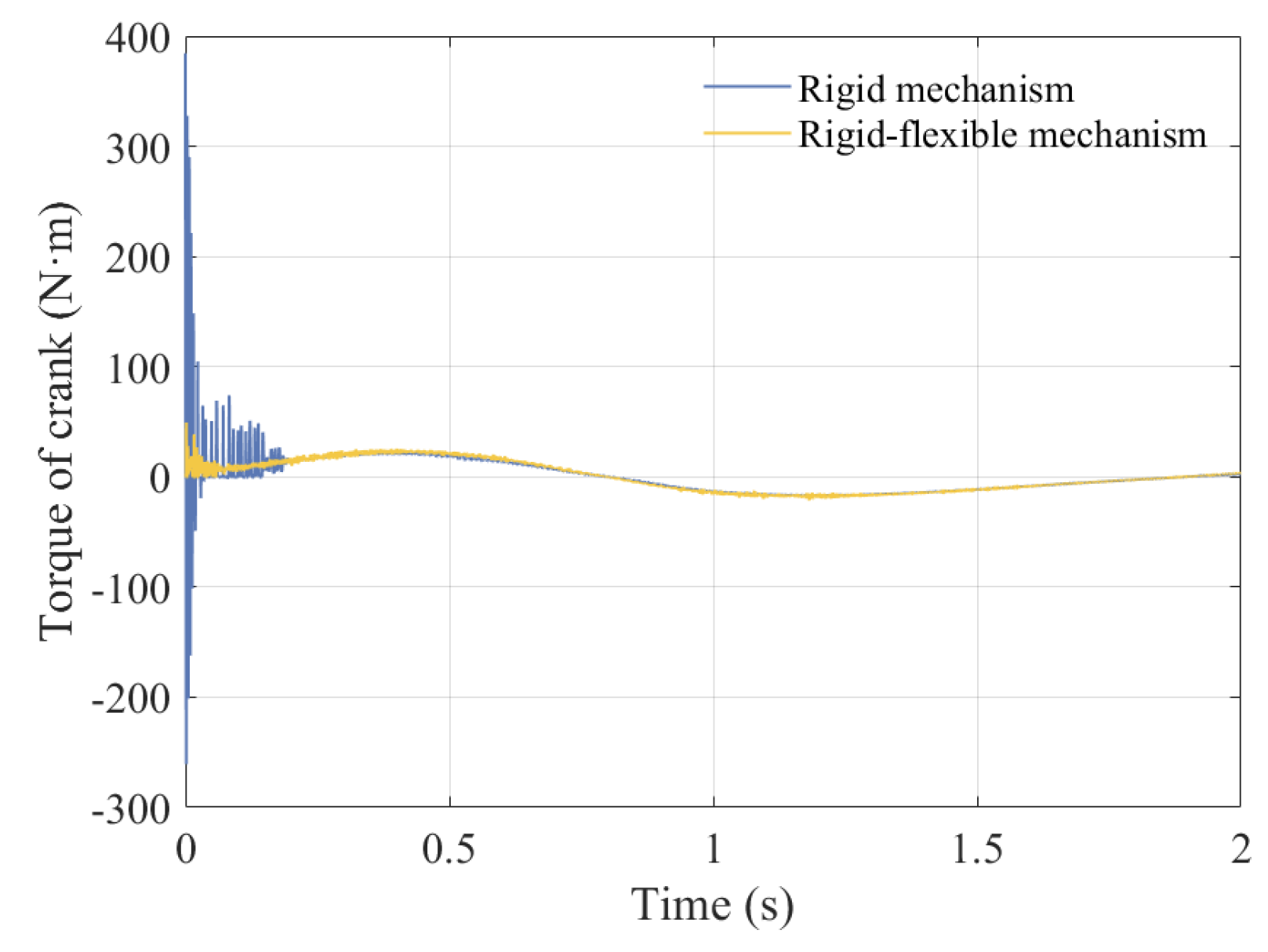
Torque of crank.

Figure 38.
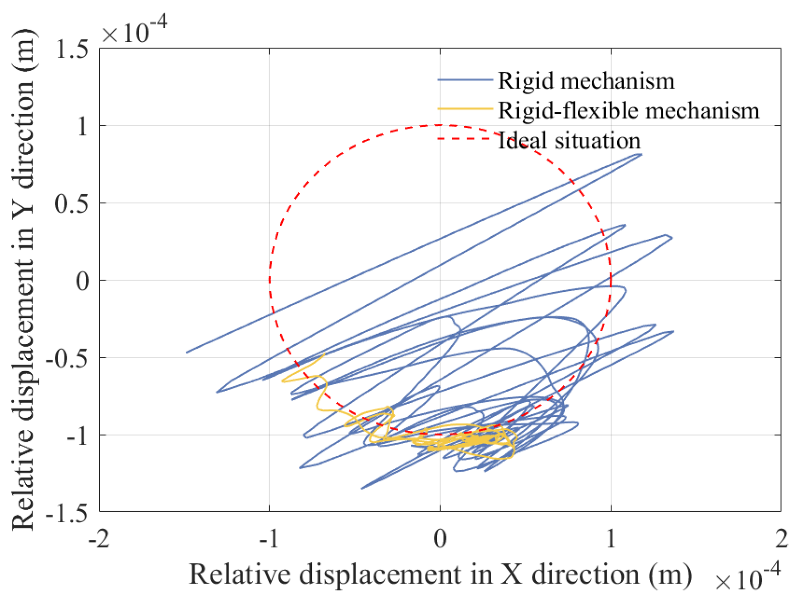
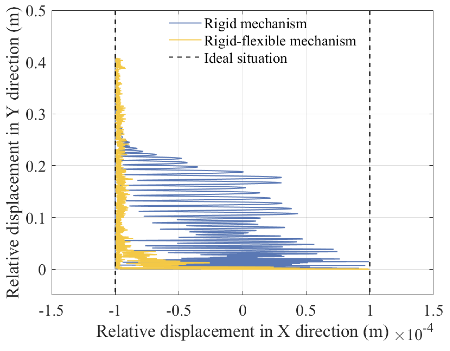
Trajectory of revolute clearance A.

Figure 39.
Trajectory of translational pair B.
From the curve of slider displacement and velocity, it can be seen that the flexibility of the component has a relatively small impact on displacement, and velocity will produce a certain amount of small vibration. According to Figure 36 and Figure 37, the elastic deformation of the component causes high-frequency vibrations in the acceleration and torque curves, but the peak values decrease. According to the center trajectory of the clearance, it is found that when considering the elastic deformation of the component, the trajectories of the shaft and slider focus on one area for high-frequency vibration. The main reason is that the components undergo elastic deformation when subjected to force, which may cause deviations between the actual motion and ideal motion of the mechanism. Meanwhile, the flexible deformation of the components will consume some energy, resulting in a decrease in the energy transfer efficiency of the mechanism.
6. Conclusions
The coupling effect of disturbance factors, such as translational clearance, revolute clearance, and component flexibility, seriously affects motion characteristics, dynamic response, and chaotic characteristics. Therefore, this paper focused on studying the impact of their coupling effects on the comprehensive performance of a symmetrical structure press mechanism.
- (1)
- A dynamic model of a mechanism considering multiple disturbance factors (including translational clearance, revolute clearance, and component flexibility) was established. The coupling effect between the revolute clearance, the translational clearance, and the elasticity of the components can make the motion of the mechanism unstable and produce a certain degree of vibration, and the dynamic response curve will also have certain fluctuations.
- (2)
- The motion state of the mechanism was quantitatively and qualitatively determined using phase diagrams, Poincaré mappings, and maximum Lyapunov exponents. It was found that revolute pair A (X direction and Y direction) and translational pair B (X direction) are more prone to chaotic states, whereas translational pair B (Y direction) is more prone to periodic motion.
- (3)
- The effect of various parameters on dynamics were analyzed, including friction coefficient, driving speed, and clearance value. As a result, it was found that with the increase in driving speed and clearance value, as well as the decrease in friction coefficient, the stability of the mechanism weakened, and the vibration of the mechanism’s dynamic response intensified.
This paper proposes an accurate modeling method for planar multilink symmetrical structure press mechanisms, comprehensively considering the coupling effect of revolute clearance and translational clearance, as well as flexible components. This method can more realistically and accurately describe the actual behavior of a mechanism during motion. By establishing a dynamic model of a mechanism with clearance for simulation analysis, the dynamic performance of mechanisms under different working conditions can be predicted, and potential design problems such as component wear and fatigue damage caused by clearance can be identified in advance. This can optimize the design parameters of the symmetrical structure press mechanism, improve design accuracy and reliability, and reduce product development costs and risks.
Author Contributions
Conceptualization, J.N. and S.J.; methodology, J.N.; software, H.Z.; validation, H.Z.; formal analysis, S.J.; investigation, J.N. and S.J.; resources, S.J.; data curation, H.Z.; writing—original draft preparation, J.N. and S.J.; writing—review and editing, J.N. and S.J.; visualization, H.Z.; supervision, S.J.; project administration, J.N.; funding acquisition, S.J. All authors have read and agreed to the published version of the manuscript.
Funding
This research was funded by [Natural Science Foundation of Shandong Province] grant number [ZR2023QE039] And The APC was funded by [Jiang Shuai]; [Open Project of Key Laboratory of Special Motors and High Voltage Electrical Appliances, Ministry of Education] grant number [KFKT202402] And The APC was funded by [Jiang Shuai].
Data Availability Statement
Data used to support the results of this research are included in this paper.
Conflicts of Interest
Author Hao Zhang was employed by the company CRDC (Jinan) Electrical Equipment Co., Ltd. The remaining authors declare that the research was conducted in the absence of any commercial or financial relationships that could be construed as a potential conflict of interest.
References
- Marques, F.; Isaac, F.; Dourado, N.; Flores, P. An enhanced formulation to model spatial revolute joints with radial and axial clearances. Mech. Mach. Theory 2017, 116, 123–144. [Google Scholar] [CrossRef]
- Muvengei, O.; Kihiu, J.; Ikua, B. Dynamic analysis of planar rigid-body mechanical systems with two-clearance revolute joints. Nonlinear Dyn. 2013, 73, 259–273. [Google Scholar] [CrossRef]
- Ambrósio, J.; Pombo, J. A unified formulation for mechanical joints with and without clearances/bushings and/or stops in the framework of multibody systems. Multibody Syst. Dyn. 2018, 42, 317–345. [Google Scholar] [CrossRef]
- Gao, S.; Fan, S.; Zhang, H. Research on the Motion Accuracy Reliability of Rigid-Flexible Coupling Mechanism with Lubrication Clearances. In Proceedings of the International Conference on Mechanical Design, Singapore, 26–28 July 2024. [Google Scholar]
- Jin, G.; Wang, Z.; Liang, D.; Wei, Z.; Chang, B.; Zhou, Y. Modeling and dynamics characteristics analysis of six-bar rocking feeding mechanism with lubricated clearance joint. Arch. Appl. Mech. 2023, 93, 2831–2854. [Google Scholar] [CrossRef]
- Guo, J.; Wang, Y.; Zhang, X.; Cao, S.; Liu, Z. Dynamic characteristic of rudder loop with rough revolute joint clearance. Nonlinear Dyn. 2024, 112, 3179–3194. [Google Scholar] [CrossRef]
- Chen, X.; Tang, Y. Dynamic Modeling, Response, and Chaos Analysis of 2-DOF Hybrid Mechanism with Revolute Clearances. Shock. Vib. 2020, 2020, 9172853. [Google Scholar] [CrossRef]
- Li, S.; Zheng, Y.; Wu, H.; Zhang, J.; Ohsaki, M.; Yang, C.; Luo, Y. Dynamics analysis of deployment process of the Bennett linkage with revolute clearance joints. Nonlinear Dyn. 2024, 112, 10911–10935. [Google Scholar] [CrossRef]
- Wang, X.; Rui, X. Dynamics modeling and simulation of tracked armored vehicle with planar clearance trunnion-bearing revolute joint. J. Mech. Sci. Technol. 2021, 35, 2285–2302. [Google Scholar] [CrossRef]
- Chen, X.; Wang, T.; Gao, S. Dynamic response errors and accuracy reliability for mechanism with multiple lubrication clearance joints. Arch. Appl. Mech. 2023, 93, 525–550. [Google Scholar] [CrossRef]
- Fu, Y.; Sun, X.; Song, Z.; Xu, J. Compound control method for reliability of the robotic arms with clearance joint. Meccanica 2024, 59, 1961–1983. [Google Scholar] [CrossRef]
- Jia, Y.; Chen, X.; Zhang, L.; Ning, C. Dynamic characteristics and reliability analysis of parallel mechanism with clearance joints and parameter uncertainties. Meccanica 2023, 58, 813–842. [Google Scholar] [CrossRef]
- Jiang, S.; Meng, K.; Xin, Y.C.; Zhu, J.N.; Lin, Y.P.; Li, Y. Chaos Identification and Dynamics Analysis of Mechanism Considering the Coupling Effect of Clearance and Elastic Deformation. Mech. Solids 2024, 59, 2179–2211. [Google Scholar] [CrossRef]
- Liang, D.; Lv, T.; Wang, Z. Research on reliability and dynamic characteristics of planar complex multi-bar mechanism considering clearance and irregular wear effect. Commun. Nonlinear Sci. Numer. Simul. 2025, 145, 108708. [Google Scholar] [CrossRef]
- Chen, X.; Jiang, S. Nonlinear dynamic behavior analysis of multi-linkage mechanism with multiple lubrication clearances. Eur. J. Mech. B/Fluids 2022, 91, 177–193. [Google Scholar] [CrossRef]
- Chen, X.; Mu, X. Theoretical and experimental studies on effect of impact load on dynamic characteristics of multi-link press mechanisms with clearances. Nonlinear Dyn. 2024, 112, 81–100. [Google Scholar] [CrossRef]
- Ma, X.-F.; Li, T.-J. Wave Analysis of Planar Deployable Structures with Revolute Clearance Joints Based on Spectral Element Method. Int. J. Appl. Mech. 2018, 10, 1850090. [Google Scholar] [CrossRef]
- Wu, X.; Sun, Y.; Wang, Y.; Chen, Y. Passive chaos suppression for the planar slider-crank mechanism with a clearance joint by attached vibro-impact oscillator. Mech. Mach. Theory 2022, 174, 104882. [Google Scholar] [CrossRef]
- Lin, Y.P.; Wang, J.C.; Zhang, J.L.; An, M.X.; Jiang, S. Research on the Dynamic and Reliability of Planar Multi-Link Mechanisms with Multiple Clearances. Mech. Solids 2024, 59, 1537–1558. [Google Scholar] [CrossRef]
- Gao, S.; Fan, S.; Wang, W. The research on the failure mechanism and dynamic reliability of lubricated clearance. Proc. Inst. Mech. Eng. Part C J. Mech. Eng. Sci. 2024, 238, 9248–9263. [Google Scholar] [CrossRef]
- Wang, J.; Meng, B.; Zhang, L.; Yu, C. Degradation modeling and reliability estimation for mechanical transmission mechanism considering the clearance between kinematic pairs. Reliab. Eng. Syst. Saf. 2024, 247, 110093. [Google Scholar] [CrossRef]
- Chen, X.; Yang, W. Dynamic modeling and analysis of spatial parallel mechanism with revolute joints considering radial and axial clearances. Nonlinear Dyn. 2021, 106, 1929–1953. [Google Scholar] [CrossRef]
- Bai, Z.; Ning, Z.; Zhou, J. Study on Wear Characteristics of Revolute Clearance Joints in Mechanical Systems. Micromachines 2022, 13, 1018. [Google Scholar] [CrossRef]
- Huang, J.; Hu, B.; Sun, S.; Xiao, M.; Peng, C.; Wang, H. Mesh Stiffness and Nonlinear Dynamic Model for a Gear Drive with Revolute Pair Clearance. Processes 2023, 11, 230. [Google Scholar] [CrossRef]
- Huang, S.; Wang, F.; Pan, T.; Wang, Z.; Zhou, H. Research on a monitoring model of revolute pair clearance based on dynamic features and thermal imaging fusion. Infrared Phys. Technol. 2023, 135, 104967. [Google Scholar] [CrossRef]
- Zhuang, F.; Wang, Q. Modeling and simulation of the nonsmooth planar rigid multibody systems with frictional translational joints. Multibody Syst. Dyn. 2013, 29, 403–423. [Google Scholar] [CrossRef]
- Wang, Y.; Liu, J.; Ning, F.; Chai, C.; Zhang, L.; Li, H. Dynamic analysis of crank slider mechanism considering 3D translational joint clearance based on variable contact area. Mech. Ind. 2025, 26, 5. [Google Scholar] [CrossRef]
- Xiao, S.; Liu, S.; Wang, H.; Lin, Y.; Song, M.; Zhang, H. Nonlinear dynamics of coupling rub-impact of double translational joints with subsidence considering the flexibility of piston rod. Nonlinear Dyn. 2020, 100, 1203–1229. [Google Scholar] [CrossRef]
- Zhang, J.; Wang, Q. Modeling and simulation of a frictional translational joint with a flexible slider and clearance. Multibody Syst. Dyn. 2016, 38, 367–389. [Google Scholar] [CrossRef]
- Qian, M.; Qin, Z.; Yan, S.; Zhang, L. A comprehensive method for the contact detection of a translational clearance joint and dynamic response after its application in a crank-slider mechanism. Mech. Mach. Theory 2020, 145, 103717. [Google Scholar] [CrossRef]
- Wu, X.; Sun, Y.; Wang, Y.; Chen, Y. Dynamic analysis of the double crank mechanism with a 3D translational clearance joint employing a variable stiffness contact force model. Nonlinear Dyn. 2019, 99, 1937–1958. [Google Scholar] [CrossRef]
- Zheng, X.; Li, J.; Wang, Q.; Liao, Q. A methodology for modeling and simulating frictional translational clearance joint in multibody systems including a flexible slider part. Mech. Mach. Theory 2019, 142, 103603. [Google Scholar] [CrossRef]
- Liu, S.; Cui, Y.; Fu, Y.; Li, B.; Lv, B.; Qian, Y. Modeling of lubricated translational joints in rigid-partially flexible multibody systems and its application in two-stroke marine diesel engines. Tribol. Int. 2022, 165, 107244. [Google Scholar] [CrossRef]
- Flores, P.; Leine, R.; Glocker, C. Modeling and analysis of planar rigid multibody systems with translational clearance joints based on the non-smooth dynamics approach. Multibody Syst. Dyn. 2009, 23, 165–190. [Google Scholar] [CrossRef]
- Zhuang, F.-F.; Wang, Q. Modeling and analysis of rigid multibody systems with driving constraints and frictional translation joints. Acta Mech. Sin. 2014, 30, 437–446. [Google Scholar] [CrossRef]
- Liu, S.; Cui, Y.; Fu, Y.; Li, B.; Lv, B.; Qian, Y. Tribo-dynamic performances and vibration transmission of lubricated translational joints in marine engines. Int. J. Mech. Sci. 2022, 231, 107599. [Google Scholar] [CrossRef]
- Ting, K.-L.; Hsu, K.-L.; Yu, Z.; Wang, J. Clearance-induced output position uncertainty of planar linkages with revolute and prismatic joints. Mech. Mach. Theory 2017, 111, 66–75. [Google Scholar] [CrossRef]
- Bai, Z.; Liu, T.; Li, J.; Zhao, J. Numerical and experimental study on dynamic characteristics of planar mechanism with mixed clearances. Mech. Based Des. Struct. Mach. 2022, 51, 6142–6165. [Google Scholar] [CrossRef]
- Tan, H.; Li, L.; Huang, Q.; Jiang, Z.; Li, Q.; Zhang, Y.; Yu, D. Influence of two kinds of clearance joints on the dynamics of planar mechanical system based on a modified contact force model. Sci. Rep. 2023, 13, 20569. [Google Scholar] [CrossRef]
- Dong, X.; Sun, Y.; Wu, X.; Wang, R. Dynamic modeling and performance analysis of toggle-linkage presses considering mixed clearances and flexibility. Int. J. Non-linear Mech. 2022, 147, 104243. [Google Scholar] [CrossRef]
- Jiang, S.; Chen, X. Test study and nonlinear dynamic analysis of planar multi-link mechanism with compound clearances. Eur. J. Mech. A/Solids 2021, 88, 104260. [Google Scholar] [CrossRef]
- Jiang, S.; Zhao, M.; Liu, J.; Lin, Y.; Xiao, L.; Jia, Y. Dynamic response and nonlinear characteristics of multi-link mechanism with clearance joints. Arch. Appl. Mech. 2023, 93, 3461–3493. [Google Scholar] [CrossRef]
- Chen, X.; Jiang, S.; Deng, Y. Dynamic Responses of Planar Multilink Mechanism considering Mixed Clearances. Shock. Vib. 2020, 2020, 8725845. [Google Scholar] [CrossRef]
- Xiao, L.; Yan, F.; Chen, T.; Zhang, S.; Jiang, S. Study on nonlinear dynamics of rigid-flexible coupling multi-link mechanism considering various kinds of clearances. Nonlinear Dyn. 2023, 111, 3279–3306. [Google Scholar] [CrossRef]
- Wu, X.; Sun, Y.; Wang, Y.; Chen, Y. Correlation dimension and bifurcation analysis for the planar slider-crank mechanism with multiple clearance joints. Multibody Syst. Dyn. 2021, 52, 95–116. [Google Scholar] [CrossRef]
- Tan, H.; Hu, Y.; Li, L. Effect of friction on the dynamic analysis of slider-crank mechanism with clearance joint. Int. J. Non-linear Mech. 2019, 115, 20–40. [Google Scholar] [CrossRef]
- Jia, Y.; Chen, X. Dynamic response analysis for multi-degrees-of-freedom parallel mechanisms with various types of three-dimensional clearance joints. Int. J. Adv. Robot. Syst. 2021, 18, 1–9. [Google Scholar]
- Ege, M.; Kucuk, S. Energy Minimization of New Robotic-Type Above-Knee Prosthesis for Higher Battery Lifetime. Appl. Sci. 2023, 13, 3868. [Google Scholar] [CrossRef]
- Kucuk, S. Simulation and design tool for performance analysis of planar parallel manipulators. Simulation 2012, 88, 542–556. [Google Scholar] [CrossRef]
- Ambrosio, J.A.C. Impact of Rigid and Flexible Multibody Systems: Deformation Description and Contact Models. Virtual Nonlinear Multibody Syst. 2003, 103, 57–81. [Google Scholar]


Disclaimer/Publisher’s Note: The statements, opinions and data contained in all publications are solely those of the individual author(s) and contributor(s) and not of MDPI and/or the editor(s). MDPI and/or the editor(s) disclaim responsibility for any injury to people or property resulting from any ideas, methods, instructions or products referred to in the content. |
© 2025 by the authors. Licensee MDPI, Basel, Switzerland. This article is an open access article distributed under the terms and conditions of the Creative Commons Attribution (CC BY) license (https://creativecommons.org/licenses/by/4.0/).