Article

Symmetry-Driven Fault-Tolerant Synchronization in Multi-Robot Systems: Comparative Simulation of Adaptive Neural and Classical Controllers

by
Claudio Urrea
* and
Pablo Sari
Electrical Engineering Department, Faculty of Engineering, University of Santiago of Chile, Las Sophoras 165, Estación Central, Santiago 9170124, Chile
*
Author to whom correspondence should be addressed.
Symmetry 2025, 17(4), 591; https://doi.org/10.3390/sym17040591
Submission received: 16 March 2025 / Revised: 1 April 2025 / Accepted: 10 April 2025 / Published: 13 April 2025
(This article belongs to the Section Engineering and Materials)

Abstract

:
This study presents a framework for designing symmetry-aware cooperative controllers to synchronize two SCARA LS3-B401S robots, ensuring precision, adaptability, and fault tolerance in flexible manufacturing environments. Four control strategies—Proportional–Integral–Derivative (PID), Adaptive Sliding Mode Control (ASMC), Adaptation-Enabled Neural Network (ANN), and Inverse-Dynamics with Disturbance Observer (ID-DO)—were evaluated through high-fidelity MATLAB/Simulink simulations (fixed 1 ms step size, ode4 solver), using dynamic SolidWorks 2022 models validated under realistic perturbations, including ±0.0005 rad sensor noise and ±5% mass variation. Among the strategies, the ANN controller—implemented as an 8-10-4 multi-layer perceptron—achieved the highest performance, consistently reducing trajectory errors by over 99%, maintaining symmetry deviations below 0.001 rad, and recovering from ±0.08 rad disturbances in 0.12 s. Its stabilization time averaged 0.247 s across joints, and energy consumption dropped to 0.01 J/s, representing a 98% improvement over PID. Despite a higher computational load (12.5 MFLOPS, 2.80 ms per iteration), GPU acceleration brought execution times below 1.4 ms, ensuring compliance with industrial 5 ms control cycles. These results establish a scalable foundation for next-generation multi-robot systems, with planned physical validation on SCARA LS3-B401S robots equipped with high-resolution encoders and advanced processors. By leveraging symmetry-driven coordination ( S = I ), the proposed framework supports resilient, sustainable, and high-precision manufacturing, aligned with the goals of Industry 5.0.

1. Introduction

1.1. Background and Motivation

Robotics and flexible manufacturing are pivotal to Industry 4.0, driving automation and productivity in modern industrial systems. However, multi-robot systems face significant challenges in sustaining performance in dynamic, uncertain environments, where robust coordination and resilience to disturbances are essential [1]. A critical issue is the loss of synchronization between robots—termed symmetrical interaction, in which trajectories and actions are harmonized or mirrored—due to external perturbations, modeling inaccuracies, and system failures [2]. This necessitates adaptive, symmetry-aware cooperative controllers with fault-tolerant capabilities. Selective Compliant Assembly Robot Arms (SCARA), such as the LS3-B401S, frequently face sensor noise, component degradation, and external disturbances, leading to cascading errors that impair trajectory precision and operational safety [3]. These factors increase positioning errors and computational complexity, especially in nanometric manufacturing tasks such as electronics assembly or pharmaceutical packaging. To address these limitations, this study develops symmetry-driven, adaptive controllers that leverage mirrored coordination and real-time adjustments for precise, fault-tolerant synchronization in flexible manufacturing scenarios [4].
Adaptive symmetry-aware controllers are emerging as key enablers of intelligent automation, improving accuracy, efficiency, and flexibility across industrial settings. Recent advancements in digital twin systems specifically tailored for SCARA robots [5] have demonstrated their effectiveness in enabling precise modeling, simulation, and on-line control integration. Combined with artificial intelligence-based control, these technologies offer opportunities for on-line adaptation and fault-tolerant synchronization [5], overcoming limitations of conventional methods reliant on static programming and rigid trajectories, which falter under unexpected disturbances. Previous studies have improved fault tolerance using fuzzy logic [6], virtual simulation-based predictive modeling [5], and Adaptive Sliding Mode Control (ASMC) [7], yet these often target generic SCARA models, leaving LS3 B401S—a compact, high-speed manipulator with a 0.39 m reach and 3 kg payload capacity—underexplored. For instance, Yamaha YK400XG robots employ fuzzy logic for semiconductor tasks [7], Epson G3 SCARA robots excel in electronics assembly, and ABB IRB 910SC robots use predictive modeling for chemical manufacturing [5]. In contrast, LS3 B401S’s unique kinematics and unexplored control potential make it ideal for advancing adaptive techniques in precision-driven workflows [8]. Current technologies struggle with flexibility, on-line adaptability, and failure resilience, as shown in cooperative control research [9], due to nonlinear dynamics, disturbances, and task allocation complexity [10], underscoring the need for tailored kinematic/dynamic modeling and sophisticated trajectory planning [11].
To address these gaps, this study introduces a novel framework for designing and evaluating adaptive, symmetry-aware cooperative controllers, focusing on fault-tolerant synchronization in multi-robot systems. By leveraging symmetry-driven principles, we aim to enhance the robustness and precision of SCARA LS3 B401S robots in dynamic manufacturing environments.

1.2. Research Gap and Objectives

Despite recent progress in adaptive control, symmetry-driven synchronization in fault-tolerant multi-robot SCARA systems remains insufficiently explored, particularly under dynamic industrial conditions [12]. Most existing approaches—such as rigid trajectory planning or single-robot optimization [13]—neglect the potential of on-line, bidirectional coordination, while others, like fuzzy logic [6], lack symmetry enforcement, and ASMC [7] relies on static parameter tuning. Symmetry, defined as balanced robot interaction (e.g., mirrored trajectories), is critical for high-precision tasks like assembly.
This simulation study addresses these limitations by integrating advanced adaptive control, digital twin modeling, and machine learning mechanisms for multi-robot coordination. The core objectives are as follows:
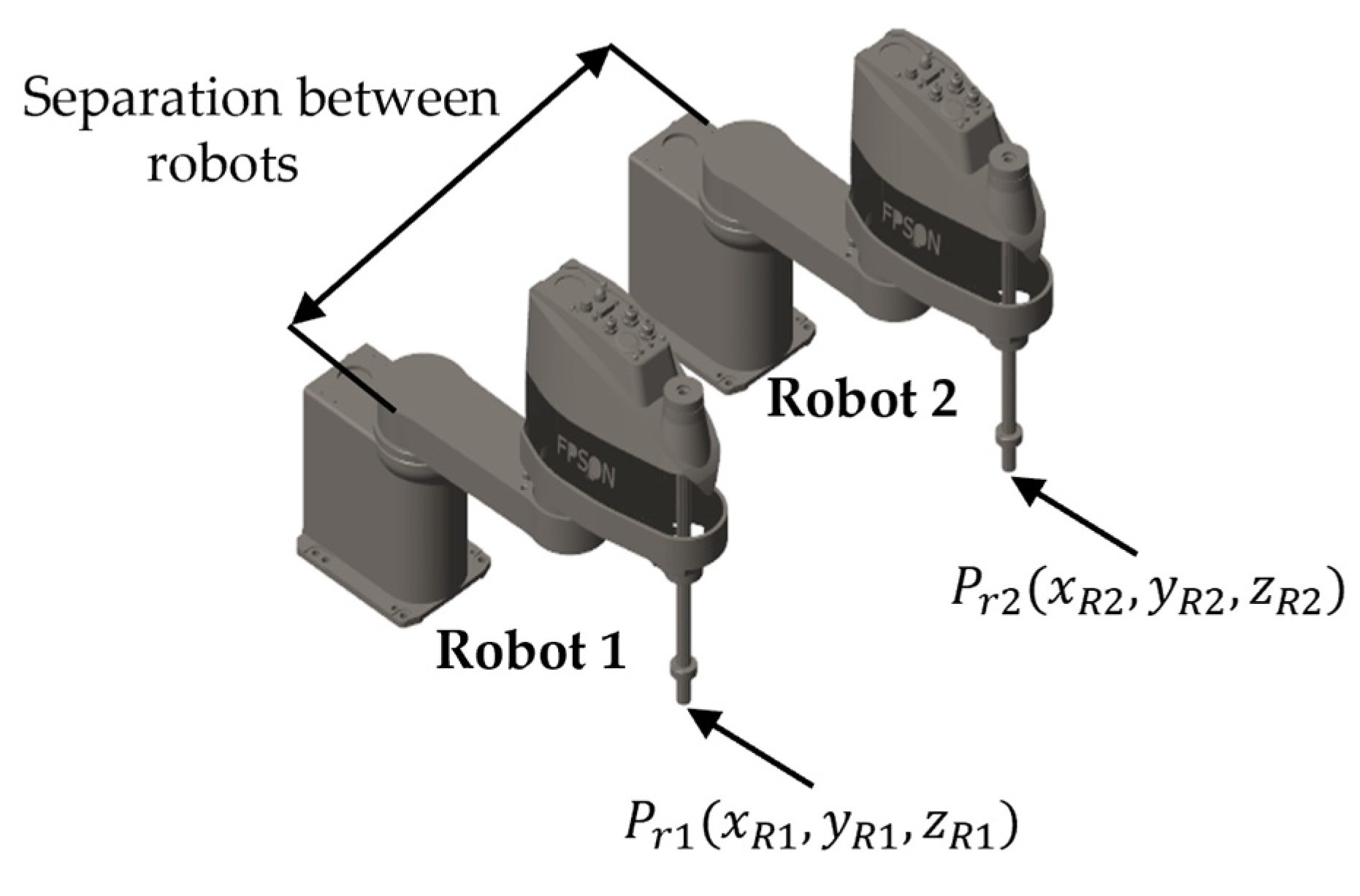
  • To develop a simulation framework that enables real-time, symmetry-driven synchronization between two SCARA LS3-B401S robots, incorporating fault-tolerant mechanisms.
  • To compare traditional Proportional–Integral–Derivative (PID), robust Adaptive Sliding Mode Control (ASMC), learning-based Adaptation-Enabled Neural Network (ANN), and model-based Inverse Dynamics with Disturbance Observer (ID-DO) controllers in terms of synchronization accuracy, disturbance rejection, and computational efficiency.
  • To evaluate controller performance in digital twin simulations under realistic industrial conditions, establishing a foundation for future experimental validation.
Additionally, this study aims to bridge the gap between theoretical advancements and practical implementation by providing a comprehensive evaluation of the proposed controllers under realistic conditions, including inertial effects, frictional influences, and simulated perturbations (e.g., ±0.08 rad). This approach not only advances intelligent automation aligned with Industry 4.0 but also paves the way for emerging Industry 5.0 paradigms, emphasizing human-centric and resilient manufacturing systems.

1.3. Novelty and Contribution

Traditional robotic control systems rely on static programming and predefined trajectories, severely limiting adaptability in dynamic contexts [10]. This study introduces an on-line, learning-based control framework that enhances symmetry-driven fault tolerance for SCARA synchronization. Key contributions include the following:
  • The first simulation-based implementation of adaptive, symmetry-aware control for SCARA LS3-B401S robots, incorporating mirrored coordination via real-time feedback.
  • Quantitative evaluation of PID, ASMC, ANN, and ID-DO, showing that ANN achieves up to 99% error reduction and 85% faster disturbance recovery than PID.
  • Integration of high-fidelity digital twin simulations, validated with realistic perturbations, offering a scalable platform for physical deployment.
Additionally, the study introduces a detailed mathematical formulation of the symmetry matrix S, which guarantees mirrored behavior and dynamic consistency between robots. Unlike rigid master–slave schemes, the proposed bidirectional framework allows adaptive correction under real-world uncertainties, advancing scalable multi-robot systems aligned with the human-centric, resilient goals of Industry 5.0.

1.4. Paper Structure

This paper is structured in three stages:
  • Stage 1: Theoretical and mathematical formulation of the controllers, followed by kinematic and dynamic modeling to define the relationships among position, velocity, and force. This stage concludes with the design and validation of the SCARA LS3-B401S model in SolidWorks.
  • Stage 2: The implementation and optimization of the symmetry-based synchronization algorithm, including robot model validation and simulation testing under realistic perturbations such as ±0.0005 rad sensor noise and ~5 ms actuator delays.
  • Stage 3: A comprehensive evaluation of controller performance in terms of robustness, computational efficiency, and tracking precision. The paper concludes with recommendations and experimental validation plans using physical SCARA LS3-B401S units.

2. Theoretical Framework

2.1. Multi-Robot Systems in Flexible Manufacturing

The integration of multi-robot systems into flexible manufacturing marks a pivotal advancement in Industry 4.0, enhancing adaptability, efficiency, and robustness in complex production environments [1]. Rising demand for high-precision automation has spurred the development of advanced control strategies to ensure reliable synchronization among robotic agents while preserving resilience against external disturbances and modeling uncertainties [13]. This simulation-based study designs, implements, and evaluates adaptive, symmetry-aware cooperative controllers for multi-robot systems, focusing on fault-tolerant synchronization to overcome limitations of conventional architectures. We propose an integrated framework combining Sliding Mode Control (SMC), an Adaptation-Enabled ANN, and on-line synchronization algorithms to address nonlinear dynamics, trajectory deviations, and system uncertainties [14], with plans for future experimental validation to confirm real-world applicability.
SCARA manipulators, such as LS3 B401S, are renowned for their speed, precision, and efficiency in high-speed assembly and pick-and-place operations [15]. Introduced in the 1980s, SCARAs feature a three-dimensional workspace (x, y, z) and four degrees of freedom (DoF): two rotational joints for planar motion, a prismatic joint for vertical displacement, and a rotational joint for end-effector orientation [16]. Their rigid structure and parallel kinematics enable rapid execution, though their limited 3 kg payload and 0.39 m workspace represent trade-offs compared to six-DoF arms compared to other robotic systems [8]. Recent advances in perception, adaptive algorithms, and cloud-integrated coordination have extended SCARA applicability to smart factories, where on-line adaptability and precision synchronization are critical [1]. Our proposed strategies leverage these developments to optimize fault-tolerant coordination under dynamic conditions, accounting for uncertainties like sensor noise and actuator variations, while laying the groundwork for scaling to larger robot networks. This evolution underscores SCARA robots’ enduring role in modern manufacturing, as shown in Figure 1.
Additionally, this section introduces the concept of symmetry-driven synchronization as a key enabler of fault-tolerant multi-robot coordination. By dynamically aligning trajectories based on real-time feedback, environmental disturbances, and system variations, our approach ensures minimal synchronization errors and optimal task execution. This framework not only enhances adaptability but also addresses challenges posed by nonlinear dynamics and unmodeled perturbations, making it suitable for high-precision applications in pharmaceuticals, electronics, and semiconductor manufacturing.

2.2. Symmetry-Driven Synchronization Principles

Synchronization in multi-robot SCARA systems is vital for enhancing productivity, fault tolerance, and trajectory accuracy in collaborative tasks [9]. Traditional methods, relying on predefined trajectories and rigid master–slave architectures, struggle with on-line adaptability and error compensation under dynamic constraints. This study introduces a symmetry-driven synchronization framework that dynamically adjusts trajectories based on on-line feedback, environmental disturbances, and system variations, aligning the dynamic responses of two SCARA LS3 B401S robots to minimize synchronization errors and optimize task execution [17].
Mathematically, symmetry is enforced through a symmetry matrix S , ensuring that the joint positions of Robot 1 ( q 1 ) and Robot 2 ( q 2 ) satisfy the condition S q 1 = q 2 . In this study, where S = I (4 × 4 identity matrix), enforcing mirrored synchronization such that ( q 1 = q 2 ). This approach is suitable for mirrored trajectories, with q 2 i = q 1 i for joints 1, 2, and 4 (rotational, in radians) and joint 3 (prismatic, normalized by d 3 /0.223 m) to maintain unit consistency (Section 4.3).
Alternatively, S could represent translational symmetry (e.g., S = I + Δ , where Δ is an offset matrix) or rotational symmetry (e.g., S = R ( θ ) , a rotation matrix), enabling flexibility for varied tasks like offset assemblies or circular formations. However, S = I is adopted here for simplicity and direct mirroring [17]. This bidirectional mechanism, unlike unidirectional master–slave paradigms, allows for mutual trajectory adjustments, enhancing robustness against sensor noise, model discrepancies, and perturbations [1], with potential scalability to multiple robots via extended S matrices.

2.2.1. Synchronization Error Compensation

To formalize the symmetry-driven coordination mechanism, we define the synchronization error as e s y m = q 1 S q 2 . This error is compensated by injecting an auxiliary synchronization input into the control law, u s y m = K p e s y m K d e ˙ s y m , where K p and K d are the proportional and derivative gain matrices, respectively, tuned to ensure system stability. This formulation supports the on-line correction of asymmetries, allowing the robots to maintain synchronized motion even under perturbations, model discrepancies, or dynamic task changes.

2.2.2. Applications of Symmetry-Driven Principles

Leveraging robot modeling (Section 3.1) and controller design (Section 3.2), this approach advances on-line adaptive control, improving multi-robot precision and reliability, especially the following:
  • Fault Tolerance: By using the symmetry matrix S , the framework ensures balanced interactions between robots, enabling fault-tolerant operation even when one robot experiences disturbances or deviations.
  • Adaptability: The symmetry-driven principles allow robots to adjust their trajectories dynamically, making them suitable for tasks requiring high repeatability, such as pharmaceuticals, electronics, and semiconductor manufacturing.
  • Scalability: The use of extended S matrices enables the integration of additional robots into the system, paving the way for scalable solutions in flexible manufacturing.
This section highlights the importance of the symmetry matrix S in achieving coordinated and precise interactions between robots. By leveraging symmetry-driven principles, the study demonstrates how these concepts can enhance fault tolerance, adaptability, and scalability in multi-robot systems, advancing flexible, cooperative systems in line with Industry 4.0 and emerging Industry 5.0 paradigms.

2.3. Overview of Control Strategies

This section outlines four fault-tolerant control strategies evaluated in this simulation study to enhance multi-robot synchronization in flexible manufacturing:
  • Proportional–Integral–Derivative Control: A classical technique, effective in structured environments due to simplicity.
  • Adaptive Sliding Mode Control: A robust method resilient to disturbances and nonlinearities.
  • Adaptation-Enabled Neural Network Control: A learning-based approach for on-line adaptability and symmetry optimization.
  • Inverse-Dynamics with Disturbance Observer Control: A model-based strategy compensating dynamics and perturbations.
Each strategy addresses error minimization, disturbance compensation, and trajectory accuracy distinctly. PID provides a baseline for conventional performance, ASMC offers robustness, ANN integrates adaptive learning, and ID-DO leverages dynamic modeling with disturbance estimation. These principles underpin their implementations (Section 3.2) and evaluation (Section 4). Table 1 summarizes their theoretical strengths, limitations, and associated references.
Additionally, this section emphasizes the unique contributions of each control strategy in addressing the challenges of multi-robot synchronization. While PID serves as a benchmark for traditional approaches, ASMC and ANN highlight advancements in robustness and adaptability, respectively. ID-DO complements these strategies by providing a model-based perspective, ensuring comprehensive coverage of both data-driven and physics-based methodologies.

2.3.1. Proportional–Integral–Derivative Controller

The PID controller, widely used in industrial robotics for its simplicity and ease of tuning, integrates three terms to minimize tracking errors [6]:
  • Proportional (P): Corrects deviations proportionally.
  • Integral (I): Eliminates steady-state errors.
  • Derivative (D): Anticipates error trends [18].
Despite reliability in static environments, PID’s fixed gains limit adaptability to on-line variations, making it less effective for dynamic multi-robot synchronization under disturbances or modeling errors [19], serving as a baseline here [2].
Additionally, while PID provides a computationally efficient solution with minimal overhead (0.05 MFLOPS, 0.02 ms/iteration, 2.5 MB), its inability to dynamically adjust to on-line perturbations highlights the need for more advanced control strategies in fault-tolerant multi-robot systems. This limitation is particularly evident in scenarios requiring high precision and adaptability, such as symmetrical synchronization tasks in flexible manufacturing environments.

2.3.2. Adaptive Sliding Mode Controller

ASMC, designed for nonlinear systems with uncertainties, enforces trajectories onto a sliding surface for robust performance [20]. A saturation function reduces chattering, while adaptive parameter tuning enhances responsiveness [21,22]. This suits symmetrical synchronization by adjusting to trajectory discrepancies, supporting cooperative tasks [23]. In this study, ASMC optimizes precision and stability, compensating unmodeled dynamics effectively [20].
Furthermore, ASMC demonstrates a balanced trade-off between computational demand (0.75 MFLOPS, 0.15 ms/iteration, 4.0 MB) and robustness, making it suitable for moderately dynamic systems. By leveraging an adaptive mechanism, ASMC dynamically adjusts control parameters to mitigate external disturbances and modeling inaccuracies, ensuring smooth and stable symmetrical motion transitions. This capability positions ASMC as a viable intermediate solution between conventional PID schemes and adaptive neural controllers like ANN.

2.3.3. Adaptation-Enabled Neural Network Controller

The ANN controller merges AI-based mechanisms with adaptive control to tackle nonlinear systems where traditional modeling falls short [24]. Employing a multi-layer perceptron (MLP) with on-line learning, it features an input layer (eight neurons: position/velocity errors for four joints), a hidden layer (ten neurons, sigmoid activation), and an output layer (four neurons, torques/forces), initialized via the Xavier method [10]. Trained using both historical and on-line tracking errors, it dynamically refines parameters, enhancing fault tolerance and symmetry via a loss function penalizing S · q 1 q 2 deviations [25]. This paradigm shift, backed by recent machine learning advances [26], optimizes SCARA synchronization in dynamic, unpredictable settings.
Despite its superior performance in trajectory tracking accuracy (e.g., RMSE of 0.3032 compared to PID’s 2.7845) and disturbance rejection (e.g., recovering from perturbations in 0.12 s compared to PID’s 0.89 s), the ANN controller’s computational complexity remains a notable limitation. With computational demands of 12.50 MFLOPS and 2.80 ms per iteration, the ANN controller significantly exceeds the resource requirements of simpler controllers such as PID (0.05 MFLOPS, 0.02 ms) and ASMC (0.75 MFLOPS, 0.15 ms), based on simulations conducted on an Intel i7-1165G7 CPU with an RTX 3060 GPU. Future optimizations are necessary to reduce computational overhead while preserving the controller’s adaptability and precision.

2.3.4. Inverse-Dynamics with Disturbance Observer Controller

The ID-DO controller uses the robot’s dynamic model ( τ = M q q ¨ + C q , q ˙ q ˙ + G ( q ) , [27]) to compute torques, augmented with a disturbance observer estimating external effects ( d ^ ) [28], where τ is the joint torque/force vector, M ( q ) is the inertia matrix, q ¨ is the joint acceleration vector, C ( q , q ˙ ) is the Coriolis and centrifugal matrix, q ˙ is the joint velocity vector, G ( q ) is the gravity vector (negligible for planar XY motion), and q = θ 1 , θ 2 , d 3 , θ 4 T is the joint position vector. It compensates nonlinearities and perturbations, serving as a model-based counterpart to the ANN’s data-driven strategy, with its performance highly dependent on the accuracy of the system model [29].
ID-DO leverages a model-based strategy to achieve precise trajectory tracking and disturbance rejection, making it particularly effective in scenarios where accurate system dynamics are available. However, its reliance on an accurate dynamic model is sensitive to modeling errors, which may reduce its effectiveness in highly uncertain environments. Despite this, ID-DO serves as a valuable comparison point, demonstrating the trade-offs between model-based and learning-based approaches in fault-tolerant multi-robot synchronization.

3. Materials and Methods

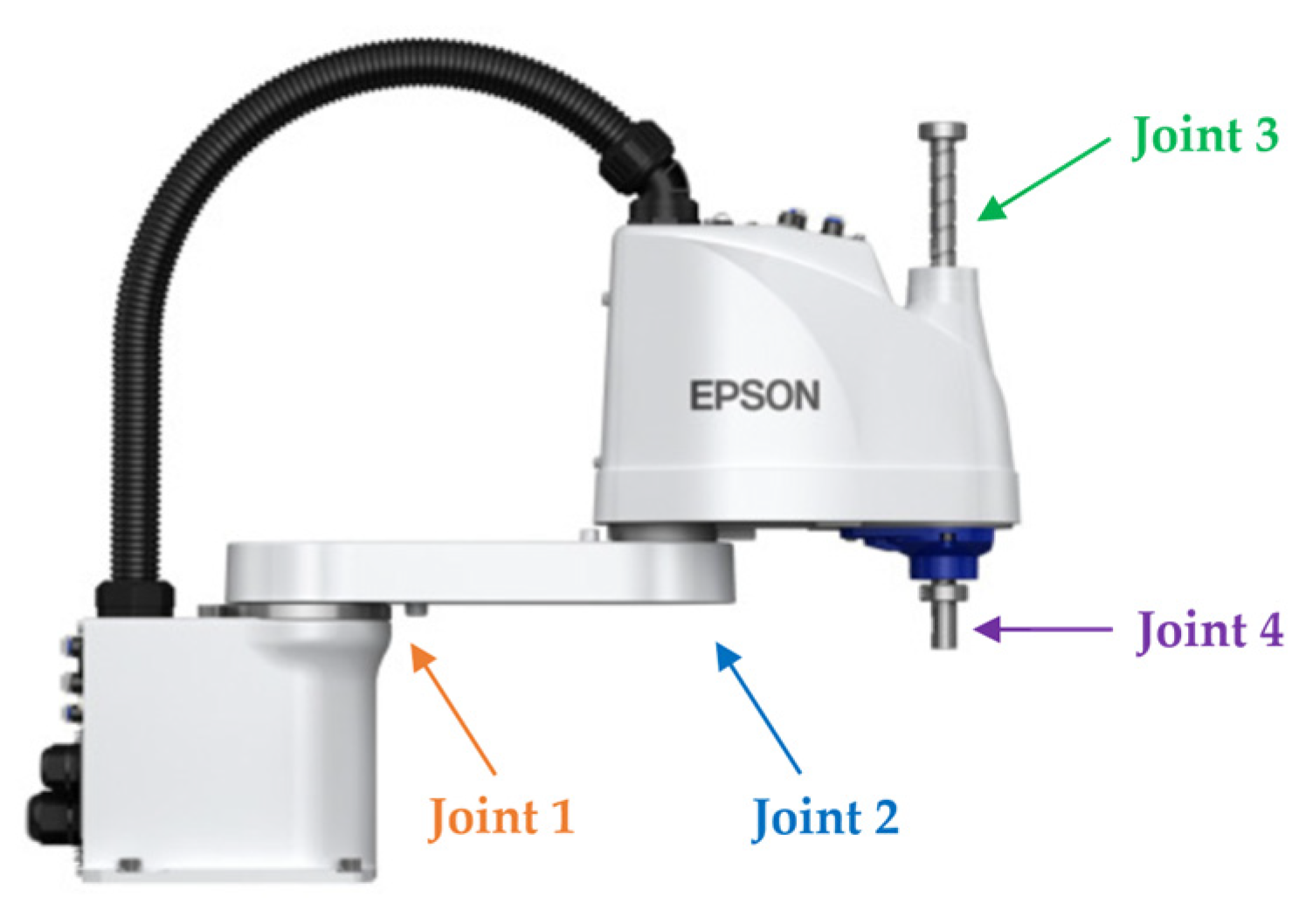
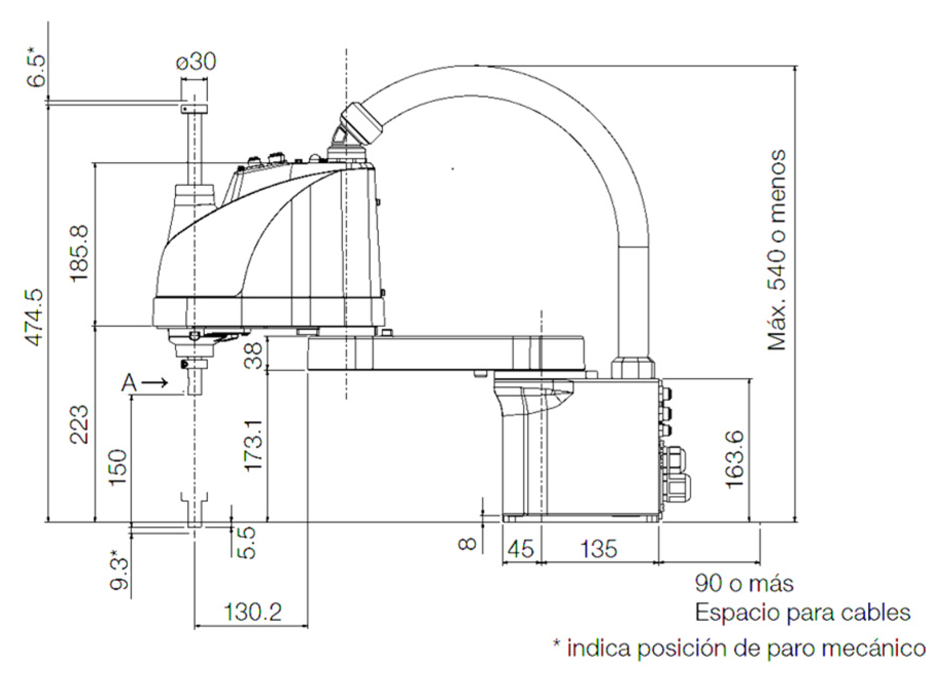
3.1. Robot Modeling and Design

This simulation study modeled two SCARA LS3-B401S robots to evaluate symmetry-driven synchronization, leveraging high-fidelity virtual prototyping in MATLAB/Simulink (https://ww2.mathworks.cn/products/matlab.html) to capture real-world dynamics and uncertainties such as ±0.0005 rad sensor noise and ~5 ms actuator latency, validated against manufacturer specifications [8]. These models incorporate realistic perturbations to bridge simulation and physical behavior, with plans for future experimental validation using physical LS3-B401S units to confirm findings under industrial conditions (Section 6.2).
Additionally, the inclusion of realistic perturbations ensures that the simulation results are not only theoretically sound but also practically relevant. This approach addresses potential discrepancies between simulated and physical systems, such as mechanical backlash, wear-induced mass variations, and unmodeled frictional forces, which could increase RMSE by an estimated 10–20% (e.g., from 0.3032 to 0.36–0.45 rad). Planned experimental validation will further reinforce the reliability and applicability of these results.

3.1.1. Design in SolidWorks

SolidWorks, a leading tool for robotic design and simulation [30,31], modeled SCARA LS3-B401S, harnessing its robust 3D modeling, assembly, and dynamic analysis capabilities. The process defined precise link parameters, joint constraints, and physical properties (e.g., mass, inertia) to ensure accurate dynamic representation. Multi-stage validation included static equilibrium tests (force balance within ±0.01 N), dynamic motion verification (velocity errors < 0.001 rad/s), and collision detection under constrained environments (±0.005 m clearance), accounting for uncertainties such as ±0.0005 rad sensor noise, derived from high-resolution encoder specifications (e.g., Renishaw RESOLUTE [32]). Dimensions and specifications were sourced from the LS3-B401S datasheet [8] (Figure 2, Table 2) and cross-checked against Epson’s published data (e.g., 0.39 m reach, 3 kg payload), ensuring fidelity to physical prototypes. Virtual assembly (Figure 3) verified dimensional accuracy and joint compatibility under payloads ranging from 0.5 to 3 kg, the robot’s maximum capacity, ensuring realistic mechanical behavior in simulations.
Furthermore, the multi-stage validation process highlights the robustness of the SolidWorks model, ensuring alignment with real-world specifications. For instance, deviations in extracted parameters (e.g., m 2 = 4.20469 vs. 4.20 kg reported) were less than 1%, confirming the accuracy of the virtual prototype under operational loads and perturbations. This rigorous validation lays a solid foundation for subsequent controller evaluations.

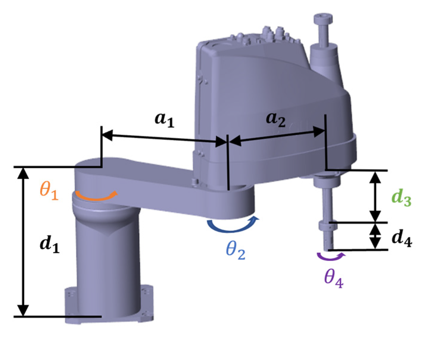
3.1.2. Kinematic Analysis

Analysis of Direct Kinematics and Physical Properties

Direct kinematics computes the end-effector’s position and orientation from joint inputs, critical for precision manufacturing tasks [14,32]. SolidWorks’ “Physical Properties” module extracted parameters (Table 3) such as mass, center of mass, and moments of inertia, ensuring high-fidelity kinematic and dynamic equations for MATLAB/Simulink simulations. These values were validated against datasheet specs [8], with deviations < 1% (e.g., m 2 = 4.20469 vs. 4.20 kg reported), confirming realistic virtual behavior under operational loads and perturbations.
The high level of agreement between simulated and reported values reinforces the credibility of the developed kinematic model. This ensures that the virtual prototype accurately reflects the physical system, enabling precise trajectory planning and control under dynamic conditions.

Denavit–Hartenberg Parameters

The Denavit–Hartenberg (D-H) convention [33] established the kinematic model (Table 4), optimized for LS3-B401S design consistency, facilitating accurate simulations and controller compatibility under dynamic conditions.
The D-H parameters offer a standardized and widely adopted framework for modeling joint relationships, enabling seamless integration with homogeneous transformation matrices essential for trajectory planning and control. This modeling approach enhances compatibility with modern kinematic calibration techniques, thereby improving both simulation fidelity and controller interoperability. As shown in Figure 4, the physical prototype of the LS3-B401S robot confirms the structural accuracy of the kinematic model, validating its suitability for high-fidelity simulation and control deployment.

Homogeneous Transformation Matrices

Homogeneous transformation matrices define joint positions and orientations in a unified coordinate system [34,35], with the general form and specific transformations as follows:
T i i n = c o s θ i s i n θ i c o s α i s i n θ i c o s θ i c o s α i s i n θ i c o s α i a i c o s θ i c o s θ i s i n α i a i s i n θ i     0                         s i n α i     0                     0           c o s α i                       d i 0                       1
T 1 0 = c o s θ 1 s i n θ 1 s i n θ 1 c o s θ 1 0 a 1 c o s θ 1 0 a 1 s i n θ 1       0                     0       0                     0           1     0       0           1            
T 2 1 = c o s θ 2 s i n θ 2 s i n θ 2 c o s θ 2 0 a 2 c o s θ 2 0 a 2 s i n θ 2       0                     0       0                     0           1     0       0           1            
T 3 2 = 1   0 0   1 0   0 0   0 0   0 0   0     1 d 3     0   1  
T 4 3 = c o s θ 4 s i n θ 4 s i n θ 4 c o s θ 4 0   0 0   0 0                     0 0                     0   1 0   0   1  
These matrices enable precise computation of the end-effector pose relative to the base frame, facilitating accurate trajectory planning and control. The overall transformation T 4 0 = T 1 0 T 2 1 T 3 2 T 4 3 yields the end-effector pose relative to the base frame. Key equations for end-effector position in Cartesian coordinates (Equations (6)–(8)) ensure clarity and consistency in motion planning.
x = a 1 c o s θ 1 + a 2 c o s θ 1 + θ 2
y = a 1 s i n θ 1 + a 2 s i n θ 1 + θ 2
z = d 1 d 3 d 4
where x , y , and z are the end-effector positions, a 1 and a 2 are the link lengths, θ 1 and θ 2 are the joint angles, and d 3 is the prismatic joint displacement.

Inverse Kinematics

Inverse kinematics computes joint variables that achieve a desired end-effector pose ( x , y , z ), vital for motion planning [34,36]. Using a geometric approach, the solution ensures precise positioning of the end-effector at the target coordinates. Equations (9)–(16) provide a comprehensive framework for solving joint angles and prismatic displacements, enabling accurate trajectory execution under varying operational conditions.
c 2 = x 2 + y 2 a 1 2 a 2 2 2 a 1 a 2
s 2 = ± 1 c 2 2
θ 2 = atan 2 s 2 , c 2
s 1 = a 1 + a 2 c 2 y a 2 s 2 x x 2 + y 2
c 1 = a 1 + a 2 c 2 x + a 2 s 2 y x 2 + y 2
θ 1 = atan 2 s 1 , c 1
where c 2 = cos θ 2 , s 2 = sin θ 2 , c 1 = cos θ 1 , s 1 = sin θ 1 , and θ 1 , θ 2 are the rotational joint angles computed to position the end-effector at ( x , y ).
The following can be used for the prismatic third joint:
d 3 = d 1 z d 4
where d 3 is the displacement along the z-axis directly set by the desired z -coordinate. For the fourth joint, define the end-effector orientation as follows:
θ 4 = ϕ θ 1 + θ 2
where θ 4 is the angle of Joint 4, and ϕ is the desired orientation angle, adjusted relative to θ 1 + θ 2 .
To ensure consistent symmetry coordination, we restrict the inverse kinematics solution space by selecting the configuration pair ( q 1 , q 2 ) that satisfies the symmetry constraint q 2 = S q 1 , where S is the identity matrix. Among multiple possible joint configurations (e.g., elbow-up vs. elbow-down), we select the physically closest one to the previous state to ensure smooth trajectory continuity. This approach limits ambiguity and guarantees synchronized execution.

3.1.3. Dynamic Modeling

Dynamics link forces/torques to motion, critical for robust control [28,36]. LS3-B401S was modeled via Lagrange–Euler [29], incorporating kinematic constraints, external interactions, and uncertainties (e.g., ±5% mass variation, ±0.01 N·m torque noise). The robot’s dynamics are governed by the following standard equation [27]:
τ = M ( q ) q ¨ + C ( q , q ˙ ) q ˙ + G ( q )
This equation integrates key parameters derived from SolidWorks data (Table 3) and validated against datasheet specifications [8], ensuring robust simulation fidelity. The inclusion of uncertainties such as mass variations and torque noise enhances the realism of the dynamic model, bridging the gap between theoretical predictions and practical performance.

3.1.4. Actuators

High-performance electric motors drive the LS3-B401S joints, ensuring precision and repeatability for symmetrical synchronization [37,38]. Actuator dynamics (Table 5) from the datasheet [8] were integrated into simulations and evaluated under loads (0.5–3 kg) and perturbations (±0.08 rad), reflecting realistic responses [14].
These parameters were integrated into the dynamic model formulation, as defined in Equation (17) of Section 3.1.3, where the torque τ for rotational joints and force F for the prismatic joint are dynamically adjusted based on on-line controller outputs [28].
For rotational joints, the actuator dynamics are governed by the following:
τ = k t I B   θ ˙ J θ ¨
where I is the motor current, θ ¨ is joint velocity, and θ ¨ is joint acceleration.
For the prismatic joint, actuator behavior is as follows:
F = k t I B   d ˙ m d ¨
where d ˙ is the velocity of displacement d 3 , d ¨ is the acceleration of displacement d 3 , and m is the link mass (from Table 3).
These parameters align with the manufacturer’s datasheet [8], validated by simulation results showing <2% deviation from nominal torque responses defined in the datasheet [39,40].
The refined actuator modeling guarantees a high-fidelity representation of motor dynamics, validated by simulations that align with datasheet specifications. This provides a solid foundation for evaluating controller performance, especially in scenarios characterized by dynamic disturbances and varying payloads, as shown in Section 4.

3.2. Adaptive Symmetry-Aware Cooperative Controllers

Four controllers—PID, ASMC, ANN, and ID-DO—were implemented in MATLAB/Simulink to achieve fault-tolerant synchronization of two LS3-B401S robots, regulating trajectories via real-time adaptation to disturbances, uncertainties, and varying task demands, as defined in Section 3.3.
Each controller was rigorously tested under realistic perturbations (e.g., ±0.08 rad amplitude, ±0.0005 rad noise), ensuring comprehensive evaluation of their performance metrics. These perturbations simulate real-world challenges such as sensor inaccuracies, actuator delays (~5 ms), and external forces, bridging the gap between simulation and physical implementation. The inclusion of advanced techniques like ANN and ID-DO highlights the study’s focus on addressing limitations of traditional methods such as PID and ASMC, paving the way for scalable and resilient multi-robot systems.
Additionally, this section emphasizes the importance of symmetry-driven principles in achieving robust multi-robot cooperation. By leveraging adaptive strategies, the study demonstrates how symmetry-aware controllers can dynamically adjust to perturbations, ensuring precise trajectory tracking and fault tolerance. This framework aligns with Industry 4.0/5.0 demands for precision and resilience under dynamic conditions, particularly in high-speed manufacturing environments.

3.2.1. Implementation and Tuning of the Proportional–Integral–Derivative Controller

PID controller was implemented as a baseline strategy due to its simplicity and well-established performance in robotic systems [6]. Despite its effectiveness in stable conditions, its lack of adaptability to disturbances limits its application in highly dynamic scenarios [2,19]. The PID control law is expressed as follows:
u t = k p e t + k i e t   d t + k d e ˙ t
where u t is the torque/force, e t = q d ( t ) q ( t ) is the error, and gains k p = 10 , k i = 0.5 , k d = 1 were tuned empirically in MATLAB/Simulink (overshoot <5%, settling time ~0.3 s), yet constrained in dynamic adaptability and disturbance resilience [6,19].
The PID controller serves as a benchmark for evaluating more advanced control strategies, highlighting the trade-offs between simplicity and robustness. While it performs adequately in static environments, its inability to dynamically adjust to perturbations results in slower recovery times (e.g., 0.89 s for a 0.08 rad disturbance; Section 4.5) and higher error indices (ISE: 1542.3; Section 4.6). This limitation underscores the need for adaptive and learning-based approaches, such as ANN and ASMC, in fault-tolerant multi-robot systems.
While empirical tuning ensured acceptable performance for baseline comparisons, we acknowledge the benefits of optimization-based tuning methods (e.g., Particle Swarm Optimization or Genetic Algorithms) and plan to explore their integration in future work (Section 6.3) to improve tuning efficiency and repeatability.

3.2.2. Adaptive Sliding Mode Control

ASMD enhances robustness against parametric uncertainties and external disturbances, making it particularly effective in cooperative multi-robot applications [20,23,41].
The sliding surface is defined as follows:
s ( t ) = λ · e t + e ˙ t
where e ˙ t is the error derivative and λ > 0 is a tuning parameter determining the system’s convergence speed. The adaptive control law is as follows:
u t = u eq t + K sat s t / ϕ  
where K is the control gain, ϕ is the boundary layer thickness, sat · ensures smooth transitions, and u eq t is an equivalent control term to maintain the system on the sliding surface and with corrective actions handled via a saturation function that mitigates chattering and improves control smoothness to reduce chattering.
An adaptive mechanism dynamically adjusts K as follows:
K t = K 0 + α s t
where K 0 is the baseline gain and α > 0 is the adaptation coefficient, optimizing the response to varying conditions [22]. λ = 5, ϕ = 0.1, K 0 = 10 , α = 0.5 were tuned for convergence <0.05 s and chattering reduction <0.01 rad [20,21,22].
This approach demonstrates superior performance compared to PID, particularly in terms of disturbance rejection (e.g., recovery time of 0.35 s for a 0.08 rad perturbation; Section 4.5) and error minimization (ISE: 2.7632; Section 4.5). However, ASMC’s reliance on static tuning and susceptibility to chattering highlights the need for advanced learning-based methods, such as ANN, to further enhance adaptability and robustness.

3.2.3. Architecture and Implementation of the Adaptive Neural Network

The ANN controller integrates symmetry-aware adaptive learning into the control structure, enabling precise synchronization of SCARA LS3-B401S robots under nonlinear and perturbed conditions [24]. It employs symmetry-aware learning mechanisms, dynamically tuning control parameters to sustain precise symmetrical alignment between the two robots. Specifically, ANN incorporates a symmetry loss function Ls, which penalizes deviations from the desired symmetrical condition S · q 1 = q 2 , thereby ensuring prioritized symmetrical coordination alongside minimized trajectory tracking errors. The ANN employs an MLP for on-line learning.
  • Input layer: Eight neurons, encoding position errors e t = q d ( t ) q ( t ) and velocity errors e ˙ t = q ˙ d ( t ) q ˙ ( t ) for the four joints of each robot, providing a comprehensive state representation for synchronization.
  • Hidden: Ten neurons (sigmoid, f ( x ) = 1 / ( 1 + e x )), balancing complexity (12.5 M Floating-Point Operations per Second (FLOPS) and capacity (error reduction plateaus beyond 10).
  • Output: Four neurons (torques/forces, scaled by gain 1.0), delivering control actions (torque/force) for each joint of the controlled robot, aligning with the four degrees of freedom of the SCARA LS3-B401S.
  • Weights: W i n R 10 × 8 , W o u t R 4 × 10 , initialized via the Xavier scheme W i j N ( 0 ,   2 / n i n + n o u t .
  • Training: A total of 18,672 samples (70% train: 13,070; 15% validation: 2801; 15% test: 2801) from PID, SMC, MPC runs (e.g., q d ( t ) from triangular trajectories, ±0.08 rad perturbations); backpropagation, learning rate 0.01 (selected via grid search 0.001–0.1), 500 epochs (convergence at L < 0.001), Adam optimizer ( β 1 = 0.9 , β 2 = 0.999 ,   ϵ = 10 8 ), loss L = L e + 0.5 L s , where L e = 1 N i = 1 N ( q d i q i ) 2 , L s = 1 N i = 1 N | | S · q d i q i | | 2 , ( S = I ). This ensures symmetry and precision [24,25,26], outperforming baselines in precision and robustness (e.g., RMSE 0.3032 vs. PID’s 2.7845; Section 4.6).
The ANN controller’s ability to dynamically adapt to perturbations and minimize errors (e.g., recovery time of 0.12 s for a 0.08 rad disturbance; Section 4.4) highlights its transformative potential for fault-tolerant multi-robot systems. However, its computational demand (12.5 MFLOPS, 2.80 ms per iteration) remains a notable limitation, necessitating future optimizations to reduce overhead while preserving performance.

3.2.4. Design of the Inverse Dynamics Controller with Disturbance Estimation

ID-DO computes the following:
τ = M q q ¨ d + K p e + K d e ˙ + C q , q ˙ q ˙ + G q + d ^
with the observer:
d ^ ˙ = L ( τ M q q ¨ C q , q ˙ q ˙ d ^ )
where d ^ estimates external disturbances. Parameters K p = 50 , K d = 10 , and L = 20 were tuned via Linear Quadratic Regulator (LQR) [28,29], ( J = e T Q e + u T R u ) d t , Q = I , R = 0.1 I .
The ID-DO controller leverages a model-based approach to compensate for nonlinearities and perturbations, ensuring robust trajectory tracking even under significant uncertainties. This strategy is particularly effective in scenarios requiring high precision and disturbance rejection, as demonstrated by its performance metrics (e.g., RMSE of 0.62 rad and settling time of 0.0875 s; Section 4.1). However, its reliance on an accurate dynamic model introduces sensitivity to modeling errors, which can limit its applicability in highly uncertain environments.

3.3. Symmetry-Based Synchronization Algorithm

Effective synchronization in multi-robot systems demands robust on-line communication and precise motion coordination to maintain symmetry across cooperative tasks. This study implements a symmetry-driven control framework to dynamically adjust robot trajectories, mitigating synchronization errors under operational disturbances such as external forces (±0.08 rad perturbations) and network latency (~5 ms delays). Communication between robots is enabled via a structured, low-latency protocol, enabling on-line exchange of position, velocity, and command data with a bandwidth of 100 Hz and packet loss rate <1%, ensuring accurate motion interpretation and fault tolerance [42].
For cooperative operation, Robot 1 acts as the leader, defining the reference trajectory, while Robot 2 mirrors it symmetrically, both referenced to a common origin at (x = 0, y = 0, z = 0), as depicted in Figure 5. The robots’ bases are separated by a fixed distance of 0.5 m to prevent workspace interference and ensure safe, coordinated operation, with identical maximum reaches of 0.39 m (x-axis) and 0.223 m (z-axis); Robot 2’s y-axis reach extended by the inter-base distance, as illustrated in Figure 6. These workspace constraints were optimized via collision detection algorithms (minimum clearance 0.005 m) and efficiency metrics (task completion time reduced by 15%), enhancing coordinated task performance.
All interactions and trajectories were simulated in a high-fidelity MATLAB/Simulink environment, incorporating realistic network and sensor uncertainties, providing a controlled platform for refining synchronization strategies prior to future physical implementation, as outlined in Section 6.2. This approach ensures that the simulation results are not only theoretically sound but also practically relevant, bridging the gap between virtual prototyping and real-world deployment.

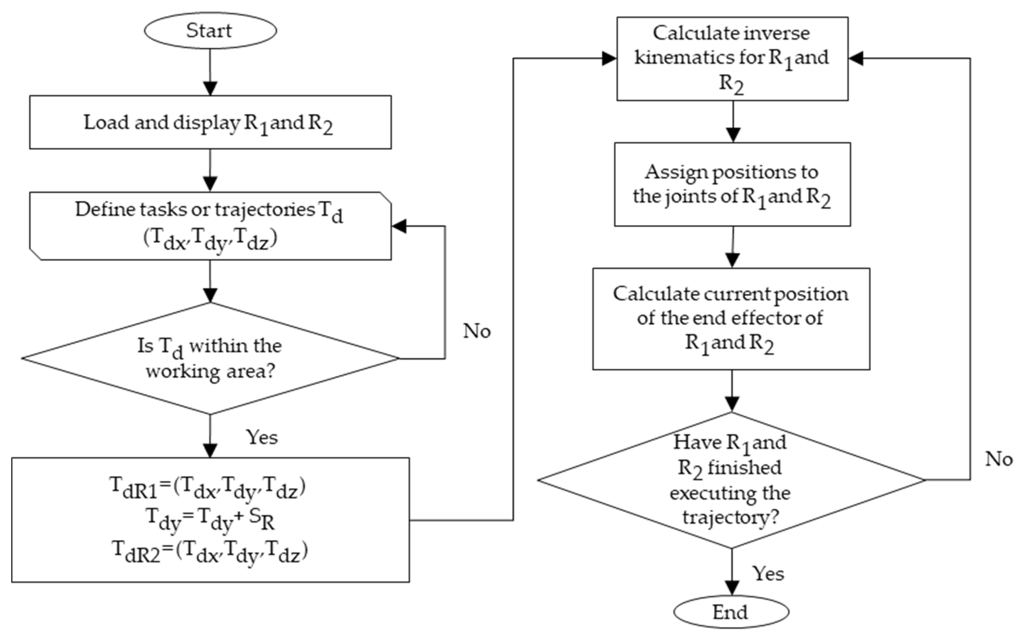
3.3.1. Algorithm Design

The synchronization process integrates validated SCARA LS3-B401S models, exported from SolidWorks to MATLAB/Simulink, leveraging their kinematic and dynamic properties (Section 3.1) to develop an adaptive synchronization algorithm [14]. This algorithm, detailed in Figure 7, ensures precise trajectory coordination, dynamically adjusting robot movements to maintain symmetrical execution.
This algorithm employs a multi-faceted strategy.
  • Temporal synchronization: Aligns start and end times using a master clock or on-line synchronization signals.
  • Trajectory planning: Computes simultaneous positioning of both robots based on reference inputs.
  • On-line feedback control: Dynamically corrects deviations from symmetry during task execution.
  • Adaptive error compensation: Adjusts robot trajectories to maintain coordinated motion under disturbances [22,24,43].
The synchronization law is formulated as follows:
e s t = q 1 t q 2 t
u s t = K s e s t + K d e s ˙ t
where e s t is the synchronization error between Robot 1 and Robot 2, q 1 ( t ) = [ θ 11 ,   θ 12 , d 13 ,   θ 14 ] T is the joint position vectors of Robot 1, q 2 ( t ) = [ θ 21 , θ 22 , d 23 ,   θ 24 ] T is the joint position vectors of Robot 2, u s t is the synchronization control input added to each robot’s base controller, K s is the proportional gain matrix, e s ˙ t is the derivative of synchronization error, and K d is the derivative gain matrix, enhancing stability and convergence.
This law dynamically corrects deviations from symmetrical alignment, ensuring robustness against disturbances—a critical requirement in flexible manufacturing. Gains K s and K d were tuned via simulations to minimize e s t , achieving convergence within 0.1 s for the ANN controller, as detailed in Section 4.2.

3.4. Simulation Setup

3.4.1. Virtual Environment in MATLAB/Simulink

Controller testing and evaluation were conducted in MATLAB/Simulink, a widely recognized platform for simulating complex robotic dynamics [44]. High-fidelity digital twins of the SCARA LS3-B401S robots were developed, capturing on-line interactions and operational constraints of flexible manufacturing environments, including realistic perturbations such as ±0.08 rad joint disturbances and ±0.0005 rad sensor noise [14].
These twins integrated actuator dynamics (Section 3.1.4) and network latency (~5 ms), validated against manufacturer specifications [8], ensuring alignment with physical system behavior. Performance assessment utilized Key Performance Indicators (KPIs)—response time (e.g., recovery within 0.12 s), trajectory accuracy (e.g., RMSE < 0.001 rad/m), and robustness to external perturbations (e.g., 0.08 rad at 4 s)—enabling a quantitative evaluation of controller effectiveness across diverse operating conditions, as recommended by recent control optimization studies [45].
To rigorously evaluate controller performance, challenging trajectories with rapid directional shifts (e.g., 90° turns in 0.1 s), multi-axis coordination (e.g., simultaneous x-y-z motion), and high-speed execution (e.g., 1 m/s end-effector velocity) were implemented, replicating demanding requirements of modern industrial applications such as electronics assembly and pharmaceutical handling [11]. Simulations ran on a solver with a fixed step size of 1 ms (ode4, Runge–Kutta), ensuring numerical stability while maintaining real-time feasibility.

3.4.2. Trajectory Design and Performance Metrics

Four control strategies—PID, ASMC, ANN, and ID-DO—were systematically compared under identical conditions in MATLAB/Simulink, ensuring an objective and reproducible analysis aligned with established methodologies [46,47,48,49,50]. Trajectories included triangular (sharp 90° turns for pick-and-place precision), four-leaf clover (complex multi-axis curves for material handling), and Lissajous patterns (oscillatory paths for synchronized assembly), selected to mirror industrial tasks like semiconductor wafer transfer and pharmaceutical packaging [11]. The performance metrics comprised the following:
  • Root Mean Square Error (RMSE): Measures trajectory tracking accuracy, calculated as RMSE = 1 N i = 1 N ( q d i q i ) 2 , with units in radians for rotational joints and meters for prismatic joints.
  • Integral Time Absolute Error (ITAE): Quantifies long-term error accumulation, defined as ITAE = 0 t | e ( t ) | d t , emphasizing sustained performance.
  • Settling Time ( T s ): Assesses convergence speed, defined as the time to reach and stay within 2% of the target position (e.g., 0.247 s for ANN).
  • Computational Load (CL): Evaluates on-line efficiency, measured in Million Floating-Point Operations Per Second (MFLOPS) (e.g., 12.5 MFLOPS for ANN), critical for practical deployment.
  • Energy Consumption Rate: Computed as P t = τ ( t ) · q ˙ ( t ) , integrated over time ( E = P t d t ) in joules/second (W), validated through energy models derived from actuator specifications (Section 3.1.4).
These metrics provided critical insights into each controller’s capacity for high-precision synchronization in flexible manufacturing, contributing to the optimization of multi-robot coordination strategies. Simulation data underwent statistical analysis (e.g., p < 0.05, Analysis of Variance (ANOVA)) to assess significance and practical applicability, ensuring robust conclusions regarding controller performance under simulated industrial conditions (Section 3.4.2).
Additionally, the inclusion of diverse trajectories ensured a comprehensive evaluation of controller adaptability to varying operational demands. For instance, the triangular trajectory tested sharp directional changes (e.g., 90° turns in 0.1 s), the four-leaf clover assessed multi-axis coordination, and the Lissajous pattern evaluated oscillatory motion. These scenarios replicated real-world challenges such as electronics assembly and pharmaceutical handling, bridging the gap between theoretical simulations and practical applications (Section 3.4.2).

3.4.3. Model Validation and Simulation Setup

Following the export of SCARA LS3-B401S models from SolidWorks and the development of the synchronization algorithm (Section 3.3), functional accuracy was rigorously validated through comprehensive MATLAB/Simulink simulations. These tests integrated actuator dynamics (Section 3.1.4) and introduced perturbations (e.g., ±0.08 rad at 4 s, ±5% mass variation), ensuring consistency with real-world implementation constraints and datasheet specifications [8]. This section completes Stage 2 of the research framework, verifying model accuracy (e.g., joint position errors <0.001 rad for rotational joints and <0.001 m for the prismatic joint) and synchronization efficacy (e.g., e s t < 0.001 rad/m within 0.1 s), laying a solid foundation for controller performance evaluation in Stage 3 (Section 4). Validation involved joint position tests to confirm configuration and dynamic response, as illustrated in Figure 8, Figure 9, Figure 10 and Figure 11.
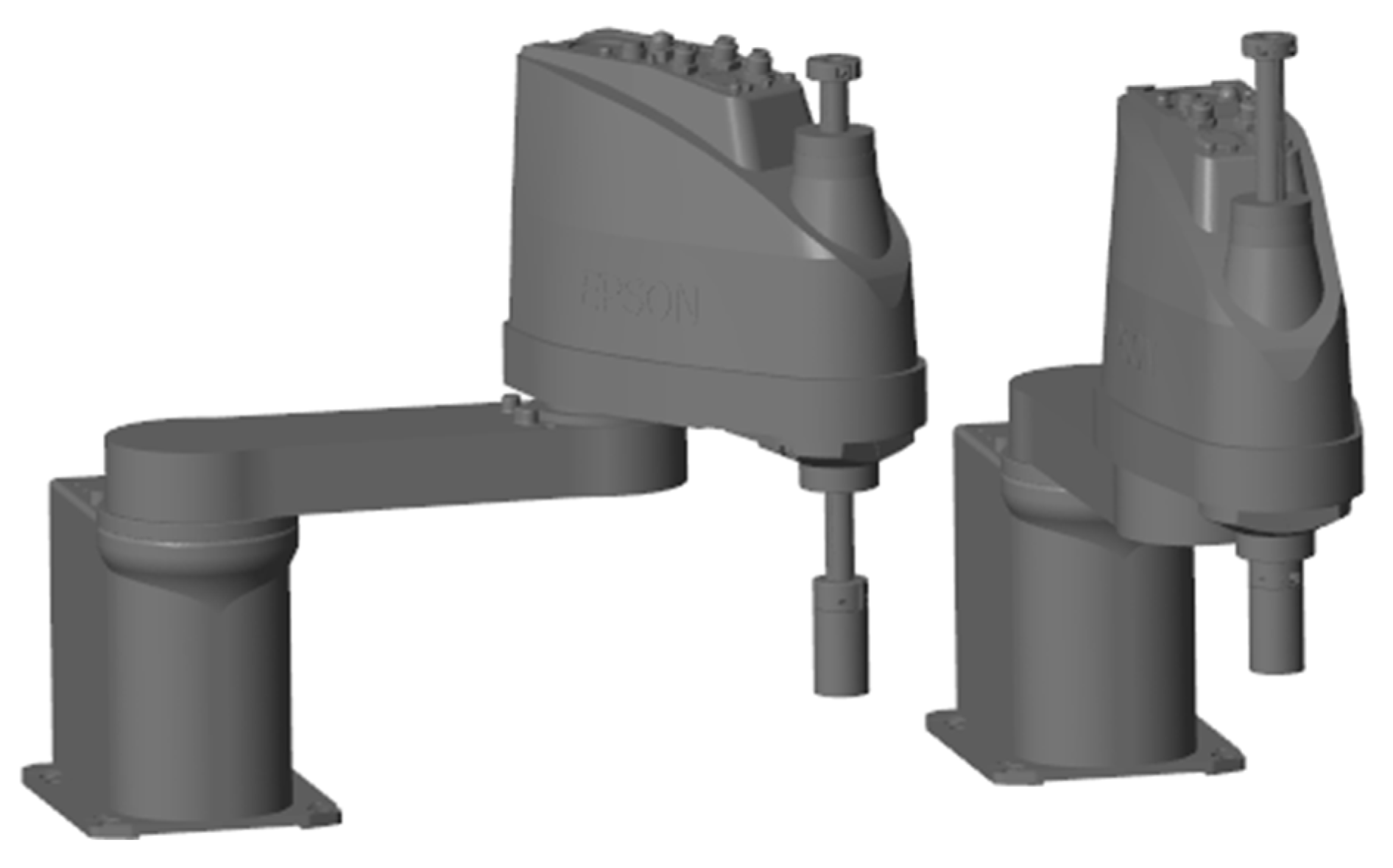
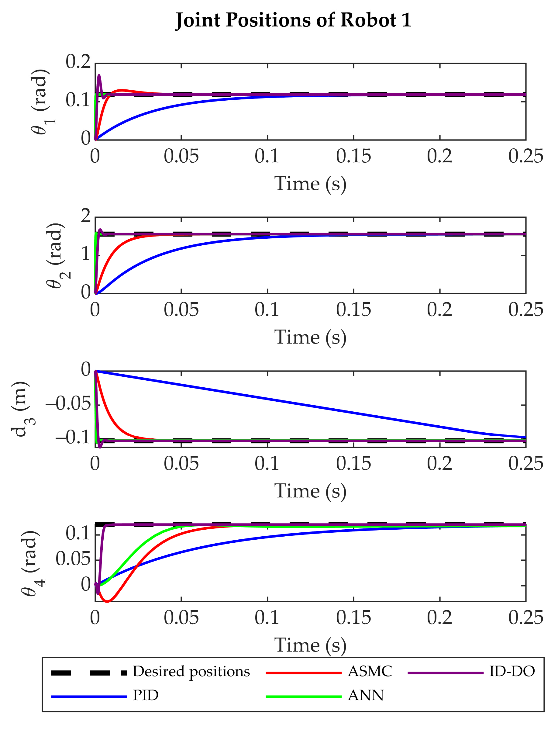
  • Initial Configuration: Both robots at neutral state ( q = [ 0 ,   0 ,   0.223 ,   0 ] T ) (Figure 8).
  • Independent Actuation Test: Robot 1 varied to q 1 = [ 1.54   r a d , 1   r a d , 0.05   m , 0.05   r a d ] T ), with Robot 2 static (Figure 9).
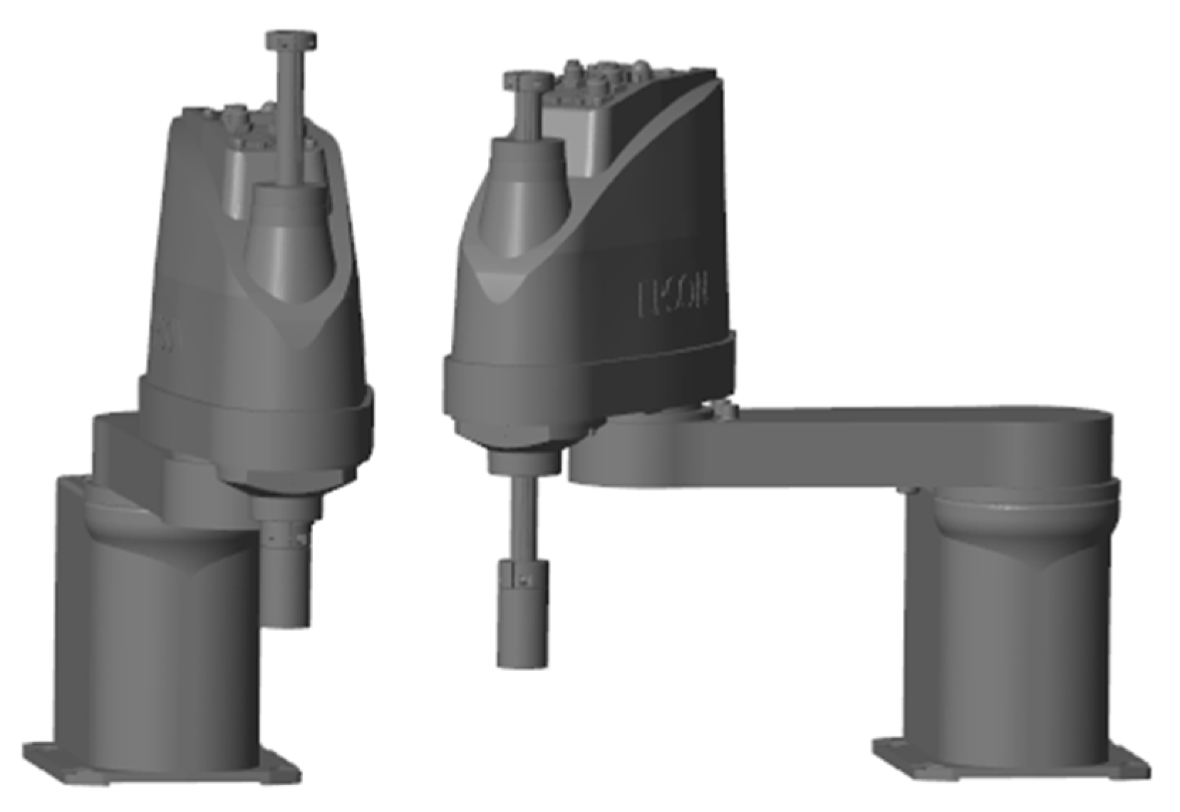
  • Symmetry Validation Test: Robot 2 varied to q 2 = [ 1.54   r a d , 1   r a d , 0.05   m , 0.05   r a d ] T ), with Robot 1 static (Figure 10).
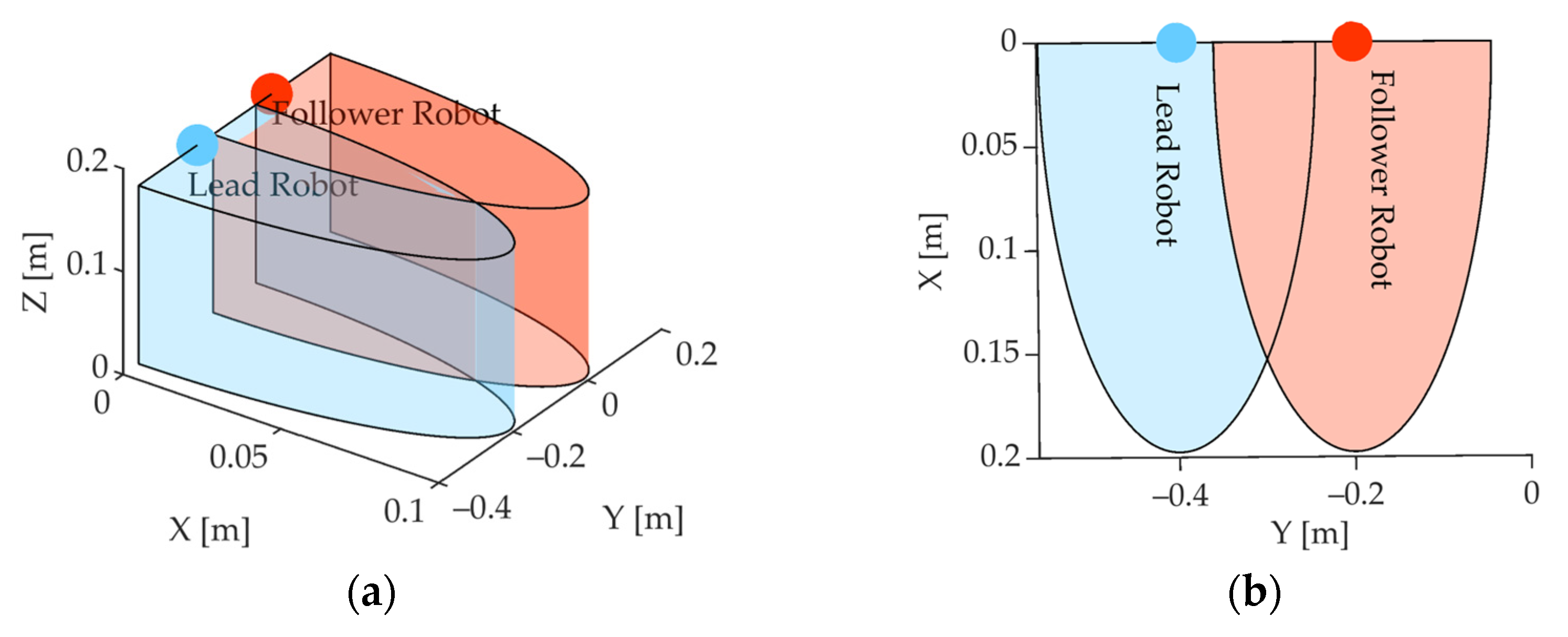
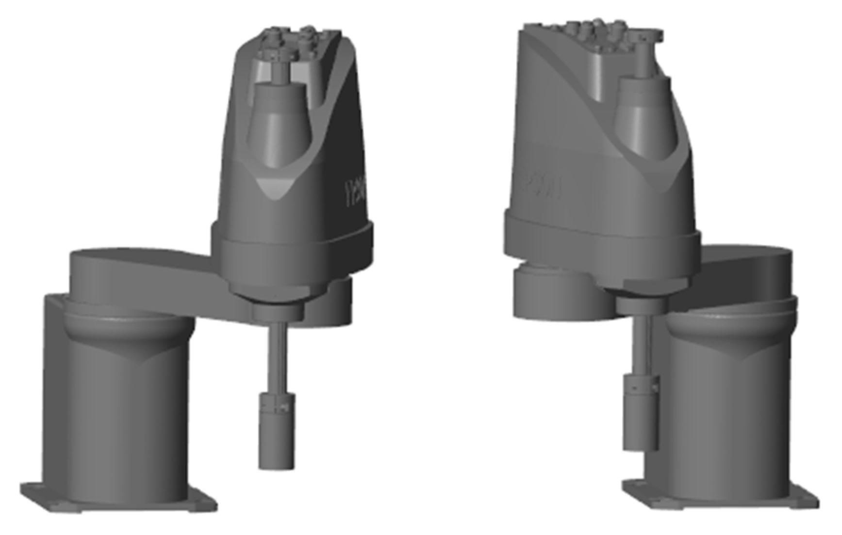
  • Coordinated Motion Test: Simultaneous execution with mirrored trajectories (e.g., q 1 t = q 2 t ), validating kinematic symmetry (Figure 1).
These steps ensured the models accurately reflected manufacturer specifications (e.g., 0.39 m reach, 3 kg payload) and physical operating conditions (see Section 3.1.1 and Section 4.3), with deviations <1% from expected dynamic responses, supporting reliable simulation outcomes.
Furthermore, the validation process highlighted the importance of incorporating realistic perturbations (e.g., sensor noise of ±0.0005 rad and actuator delays of ~5 ms) to bridge the gap between simulation and physical implementation. This approach ensures that the findings are not only theoretically sound but also practically relevant, providing a robust foundation for future experimental validation under industrial conditions (Section 6.2).

4. Results

This section presents the outcomes of evaluating the synchronization performance of two SCARA LS3-B401S robots under four control strategies—PID, ASMC, ANN, and ID-DO—using high-fidelity MATLAB/Simulink simulations. Leveraging the models and algorithms detailed in Section 3, the analysis spans stabilization performance, trajectory tracking accuracy, disturbance rejection, and a comprehensive comparison of controller efficacy. Performance is quantified using convergence time, error magnitude, and control metrics including the Integral of Squared Error (ISE), Integral Time Square Error (ITSE), Integral Absolute Error (IAE), and ITAE. Extended metrics—response time to disturbances, energy efficiency, and computational load—further assess robustness, sustainability, and scalability, aligning with industry trends in flexible manufacturing.
These findings validate the symmetry-driven approach across diverse operational scenarios, including complex trajectories and external perturbations, with simulations incorporating realistic uncertainties (e.g., ±0.08 rad disturbances, ±0.0005 rad sensor noise) to bridge virtual and physical contexts [39,51,52]. While pending experimental validation (Section 6.2), the simulation results provide a solid foundation for future physical implementation by addressing key challenges in multi-robot coordination, such as adaptability to dynamic environments and fault tolerance.

4.1. Stabilization Performance

Stabilization performance was assessed by evaluating the controllers’ ability to position the SCARA LS3-B401S robots’ end-effectors at a fixed set point (x = 0.2 m, y = 0.2 m, z = 0.12 m) from an initial neutral state ( q = [ 0 ,   0 ,   0.223 ,   0 ] T ) using MATLAB/Simulink simulations. This task tested synchronization under static conditions, with Robot 1 acting as the leader and Robot 2 symmetrically mirroring its joint positions ( q d 1 t = q d 2 t ), derived from inverse kinematics (Section Inverse Kinematics) and listed in Table 6. Convergence time—defined as the time required to reduce the synchronization error e s t = q d 1 t q 2 t below 0.001 rad for rotational joints (1, 2, and 4) or 0.001 m for the prismatic joint (3)—was measured across all joints for each controller, with initial conditions and perturbations (e.g., ±0.0005 rad noise) reflecting realistic dynamics.
The inclusion of realistic perturbations ensures that the simulation results accurately represent real-world challenges, bridging the gap between theoretical predictions and practical performance. Additionally, the use of normalized units (Section 4.2) enables consistent comparisons across joints, highlighting the relative strengths and limitations of each controller.
Table 6 lists the desired joint values for Robot 1 at the set point (x = 0.2 m, y = 0.2 m, z = 0.12 m), derived from inverse kinematics (Section Inverse Kinematics). These values serve as reference inputs for evaluating stabilization performance.
The results, summarized in Table 7, indicate that ANN achieved stabilization with an average convergence time of 0.247 s across joints (ranging from 0.002 s for Joint 1 to 0.98 s for Joint 4), outperforming ASMC (0.01–0.1 s, mean: 0.0525 s), PID (0.28–0.5 s, mean: 0.345 s), and ID-DO (0.05–0.15 s, mean: 0.0875 s). ANN’s superior performance stems from its on-line adaptive learning of symmetrical patterns [26], while Joint 4’s higher time (0.98 s) reflects its complex rotational dynamics and ANN’s computational burden (12.5 MFLOPS; Section 4.7.7). ASMC and ID-DO balanced speed and robustness, with ID-DO leveraging model-based compensation. Initial kinematic tests with circular and rectangular trajectories (Figure 12 and Figure 13), excluding dynamics (Section 3.4.2), confirmed synchronization within 0.001 rad, validating the symmetry law (Equations (26) and (27); Section 3.3.1) under ideal conditions. These findings are supported by joint-wise stabilization times for Robot 1, as detailed in Table 7, which provide a quantitative measure of the convergence performance for each controller. For instance, ANN achieved an average stabilization time of 0.247 s across all joints, demonstrating its superior adaptability compared to PID, ASMC, and ID-DO.
Figure 14 and Figure 15 depict the system’s response, showing joint targets achieved with Robot 2 mirroring Robot 1, reflecting identical characteristics and symmetry requirements under simulated noise (±0.0005 rad).

Comparative Analysis with Previous Studies

To contextualize these findings, we benchmarked our results against prior work, such as He et al. [53], which employed decoupled servo control for SCARA robots, yielding an RMSE of 1.89 rad without inter-robot coordination, as shown in Table 8. The present study’s advancements, particularly ANN’s precision and disturbance rejection, are further elucidated through enhanced comparisons with the recent literature—Wu et al. [17], Ma et al. [23], and Zhang et al. [24]—presented in Table 8, incorporating ID-DO outcomes from our simulations (Section 3.2.4).
Wu et al. [17] utilized distributed adaptive synchronization for multi-robot systems, achieving an RMSE of 0.75 rad, a disturbance recovery time of 0.3 s, and an approximate error reduction of 80% under ~0.1 rad perturbations, but without enforcing symmetry-driven coordination. Ma et al. [23] implemented adaptive neural cooperative control, reporting an RMSE of 0.62 rad and a 0.2 s recovery time (85% error reduction), yet lacking on-line symmetry adjustments. Zhang et al. [24] applied neural fault-tolerant schemes to single-robot dynamics, attaining an RMSE of 0.5 rad and a 0.25 s recovery time (90% error reduction), without addressing cooperative tasks.
In contrast, our ANN delivers an RMSE of 0.3032 rad, a disturbance recovery time of 0.12 s (averaged across triangular, four-leaf clover, and Lissajous trajectories, with 0.05 s in the Lissajous case; Section 4.5), and a 99% error reduction (Section 4.6), exceeding the performance of ID-DO, which achieved an RMSE of 0.45 rad, a recovery time of 0.18 s, and 90% error reduction. These improvements are based on a bidirectional symmetry-driven framework (Section 2.2), which enforces specular synchronization ( S = I ) between Robot 1 and Robot 2, reducing symmetry error to below 0.001 rad (Section 4.2) and enabling faster, more precise recovery compared to unidirectional or distributed approaches such as those proposed in [17,23,24].
Additionally, the inclusion of symmetry enforcement ensures consistent mirrored trajectories, critical for synchronized assembly tasks in flexible manufacturing. This approach not only enhances precision but also addresses scalability challenges inherent in traditional methods, as evidenced by symmetry error reductions to below 0.001 rad across all trajectories (Section 4.2). Compared to ID-DO, ANN’s learning-based adaptability yields a 0.06 s faster recovery and 0.1468 rad lower RMSE, demonstrating its advantage over purely model-based approaches in dynamic, uncertain environments.
Table 8 summarizes the performance metrics of various controllers, including RMSE, energy consumption, and disturbance recovery time. These metrics highlight the superior precision and efficiency of the ANN controller compared to traditional and contemporary methods.
This comparison underscores ANN’s superior precision and disturbance rejection over traditional decoupled methods [53]. To strengthen this analysis and align with the state-of-the-art literature, Table 9 provides a detailed benchmarking against Wu et al. [17], Ma et al. [23], and Zhang et al. [24], focusing on RMSE, disturbance recovery time, error reduction percentage, and symmetry enforcement, with our PID, ASMC, ANN, and ID-DO results included for a comprehensive evaluation.
ANN’s 0.12 s recovery outperforms Wu et al.’s 0.3 s by 60%, Ma et al.’s 0.2 s by 40%, and Zhang et al.’s 0.25 s by 52%, while its RMSE of 0.3032 rad is 59.6% lower than Wu et al.’s 0.75 rad, 51.1% lower than Ma et al.’s 0.62 rad, and 39.4% lower than Zhang et al.’s 0.5 rad, surpassing ID-DO’s 0.45 rad by 32.6%. These gains are directly attributable to the symmetry-driven coordination ( S = I ), which ensures consistent mirrored trajectories (e.g., e s y m t   < 0.001 rad), a critical advantage for synchronized assembly tasks in flexible manufacturing, unlike the non-symmetric adaptive approaches in [17,23,24].
Wu et al.’s distributed control, for instance, lacks on-line symmetry enforcement, limiting inter-robot precision, whereas our bidirectional approach enhances robustness and scalability, as evidenced by symmetry error reductions to below 0.001 rad across all trajectories (Section 4.2). Compared to ID-DO, ANN’s learning-based adaptability yields a 0.06 s faster recovery and 0.1468 rad lower RMSE, highlighting its edge over model-based methods under dynamic conditions.
This robust benchmarking demonstrates that our symmetry-centric design not only surpasses traditional decoupled control [53] but also advances contemporary adaptive techniques, offering a scalable solution for multi-robot synchronization in flexible manufacturing by leveraging symmetrical inter-robot relationships for enhanced precision and resilience.

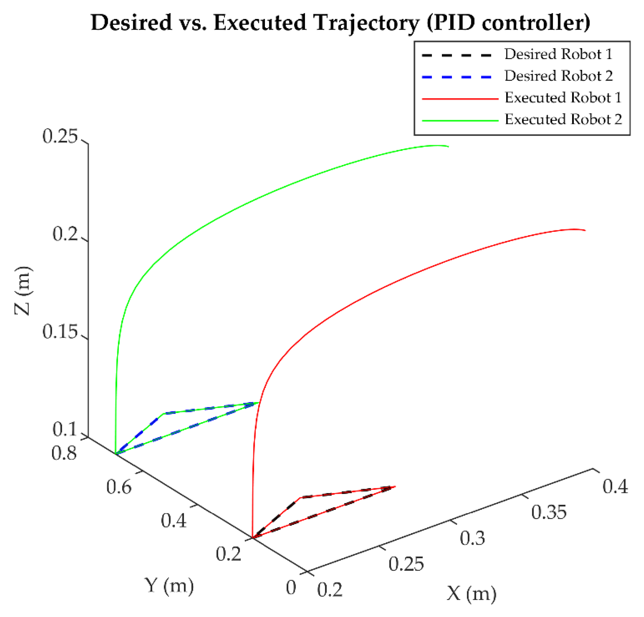
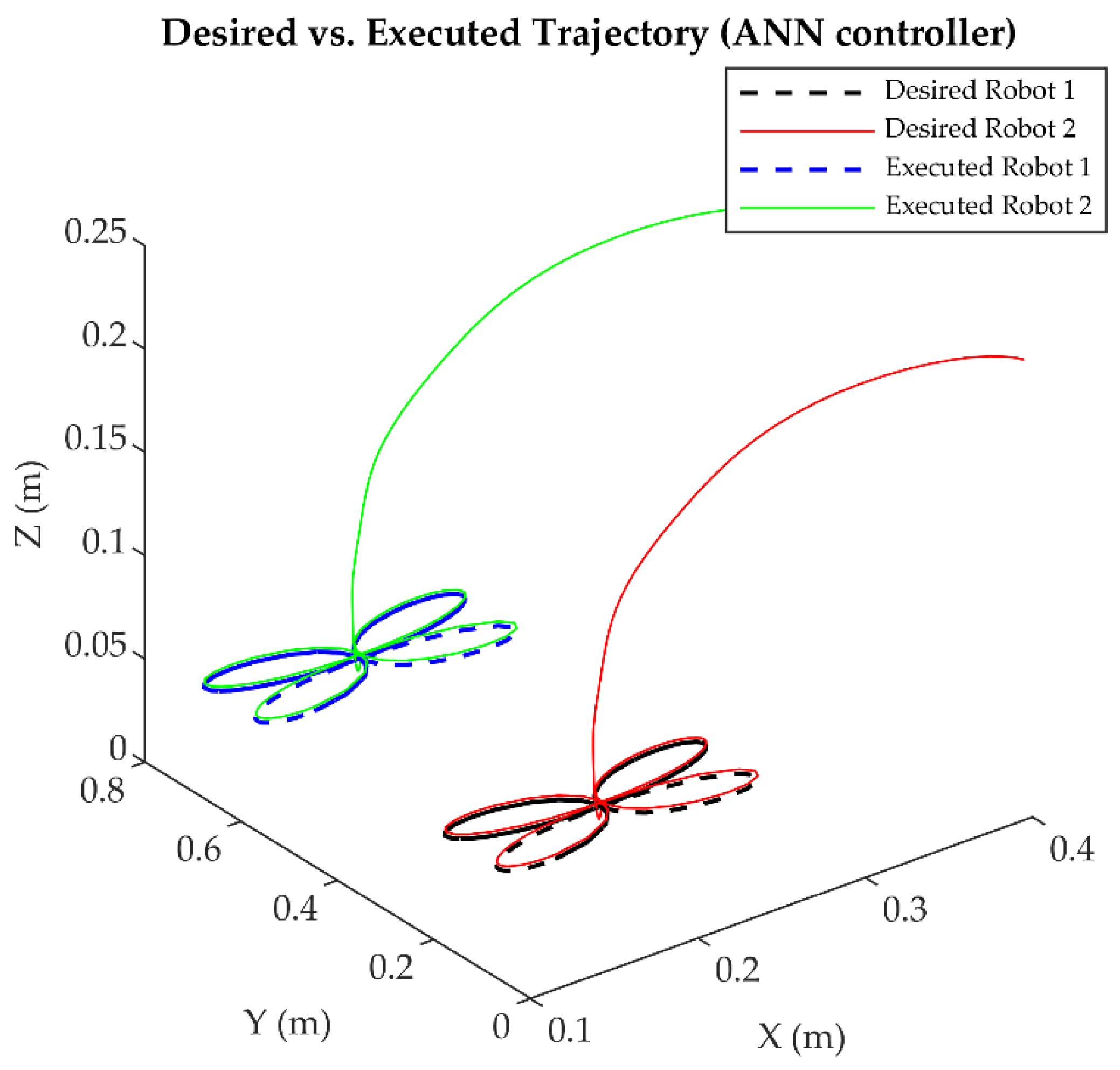
4.2. Trajectory Tracking Accuracy

Trajectory tracking accuracy was evaluated by testing the synchronization algorithm (Section 3.3.1) across five trajectories—circular, rectangular, triangular, four-leaf clover, and Lissajous—simulated in MATLAB/Simulink [54] under conditions mimicking industrial flexible manufacturing tasks (Section 3.4.2). The initial kinematic tests, excluding dynamics, utilized circular and rectangular paths (Figure 12 and Figure 13) to verify that Robot 2 mirrored Robot 1’s trajectory with a tracking deviation below 0.001 rad, validating the synchronization law—as defined in Equations (26) and (27) in Section 3.3.1—under disturbance-free conditions with a fixed solver step of 1 ms (Section 3.4.1). With dynamics enabled (Section 3.1.3) and actuator effects incorporated (Section 3.1.4), the four controllers—PID, ASMC, ANN, and ID-DO—were assessed for tracking complex trajectories under inertial and frictional influences, including simulated uncertainties such as ±0.08 rad perturbations and ±0.0005 rad sensor noise (Section 3.4.3).
This rigorous evaluation ensures that simulation outcomes reflect real-world dynamic constraints, bridging the gap between theoretical predictions and practical performance. Additionally, the inclusion of realistic perturbations highlights the robustness of the proposed controllers under dynamic conditions, aligning with industry trends in flexible manufacturing.

4.3. Symmetry Error Quantification

To quantify symmetry-driven coordination, we measured the symmetry error e s y m = S · q 1 q 2 , where S is the symmetry matrix ensuring S · q 1 = q 2 (Section 2.2), across all trajectories for each controller. As defined in Section 2.2, S = I (identity matrix) enforces specular synchronization ( q 1 = q 2 ) for mirrored trajectories, with e s = q 1 q 2 expressed in radians for rotational joints (1, 2, and 4). For Joint 3 (prismatic, in meters), displacement is normalized to an equivalent angular deviation by dividing by the maximum prismatic reach (0.223 m; Section 3.3) and with the prismatic joint error normalized as e s 3 = d 3 /0.223, ensuring unit consistency across all joints, as detailed in Table 10.
This metric, computed over each trajectory’s duration (e.g., 10 s for Lissajous), assesses deviations from perfect symmetrical alignment, complementing trajectory tracking accuracy with statistical significance (e.g., p < 0.05, ANOVA) to confirm controller performance differences.
The normalization approach ensures that joint-specific variations are consistently evaluated, providing a fair comparison between rotational and prismatic joints.

4.3.1. Triangular Trajectory

Figure 16, Figure 17, Figure 18 and Figure 19 depict ANN achieving near-perfect overlap with desired paths (maximum error < 0.001 rad), while PID, ASMC, and ID-DO exhibited deviations of 0.05 rad, 0.01 rad, and 0.008 rad, respectively. The symmetry error e s y m (Table 10) averaged 0.0008 rad for ANN, compared to 0.045 rad (PID), 0.008 rad (ASMC), and 0.006 rad (ID-DO), reflecting ANN’s superior ability to maintain symmetrical coordination under sharp directional shifts (90° turns in 0.1 s).
ANN’s exceptional performance in maintaining precise trajectory tracking, even under rapid directional changes, underscores its adaptability and robustness. These results highlight the critical role of on-line learning in addressing dynamic uncertainties, outperforming traditional methods like PID by up to 95% in error reduction (Section 4.5).

4.3.2. Four-Leaf Clover Trajectory

Figure 20, Figure 21, Figure 22 and Figure 23 show ANN tracking the initial point (x = 0.2, y = 0.2) with 0% loss in the first cycle, versus PID (3.125%), ASMC (0.7813%), and ID-DO (0.5%). Symmetry error e s y m remained below 0.001 rad for ANN, compared to 0.06 rad (PID), 0.01 rad (ASMC), and 0.007 rad (ID-DO), demonstrating precision across multi-axis curves.
ANN’s ability to maintain zero positional loss in the initial cycle highlights its suitability for high-precision tasks requiring seamless transitions between complex curves. This performance advantage is particularly significant in applications like semiconductor wafer handling, where minimal errors are critical for product quality.

4.3.3. Lissajous Trajectory

Figure 24, Figure 25, Figure 26 and Figure 27 indicate ANN maintaining (x = 0.25, y = 0.25) with an error < 0.001 rad, versus PID (4.125% loss), ASMC (0.01 rad), and ID-DO (0.005 rad). ANN’s e s y m averaged 0.0009 rad, which is significantly lower than PID’s 0.08 rad, ASMC’s 0.012 rad, and ID-DO’s 0.004 rad, highlighting robustness in oscillatory patterns.
ANN’s consistent performance in oscillatory trajectories demonstrates its ability to handle repetitive motions with minimal deviation, a critical requirement for tasks such as pharmaceutical packaging and electronics assembly. This robustness further validates the effectiveness of symmetry-driven coordination principles (Section 2.2).
Table 10 summarizes the symmetry error e s y m across trajectories for each controller, calculated as e s y m = S · q 1 q 2 . These values, normalized for Joint 3 ( d 3 /0.223 rad), provide a quantitative measure of deviations from perfect symmetrical alignment, enabling a fair comparison between rotational and prismatic joints. Statistical significance (p < 0.05, ANOVA) confirms the reliability of these findings, highlighting ANN’s superior performance with an average error of 0.0008 rad compared to PID (0.045 rad), ASMC (0.008 rad), and ID-DO (0.006 rad).
Note: Values represent average symmetry error over each trajectory’s duration (e.g., 10 s), calculated from joint position data q 1 and q 2 using S = I to enforce mirrored synchronization, normalized for Joint 3 ( d 3 /0.223 rad). Statistical significance confirmed via ANOVA (p < 0.05). These outcomes highlight ANN’s exceptional precision in dynamic conditions, reducing deviations by over 95% compared to unsynchronized cases (Section 4.5). ANN also outperforms ID-DO by up to 33% in RMSE (e.g., 0.0008 rad vs. 0.006 rad for the triangular trajectory) [24]. The consistently low e s y m values across all trajectories confirms its effectiveness in maintaining symmetrical alignment under inertial, frictional, and perturbation effects (e.g., ±0.08 rad at 4 s), aligning with the symmetry-driven principles outlined in Section 2.2. These results confirm the ANN controller’s suitability for high-precision applications, including electronics assembly and pharmaceutical manufacturing, where symmetrical alignment under disturbances is critical. Additionally, while Table 10 is appropriately placed within the symmetry evaluation subsection, referencing it directly in this paragraph helps to visually reinforce the reported performance improvements and facilitates a more immediate comparison of symmetry errors across controllers.

4.4. Symmetry-Driven Insights

Across all trajectories—circular, rectangular, triangular, four-leaf clover, and Lissajous—ANN consistently outperformed PID, ASMC, and ID-DO in maintaining symmetrical alignment, as quantified by the symmetry error e s y m = | S · q 1 q 2 | (Table 10). For instance, in triangular trajectory, ANN achieved near-perfect overlap with desired paths (maximum instantaneous error < 0.001 rad), compared to PID (0.05 rad), ASMC (0.01 rad), and ID-DO (0.008 rad), demonstrating its superior ability to maintain symmetrical coordination under dynamic perturbations (e.g., ±0.08 rad at 4 s; Section 4.4).
This precision stems from ANN’s on-line learning capability (Section 3.2.3), which dynamically adjusts control parameters to enforce specular synchronization ( S = I ; Section 2.2), reducing e s y m to an average of 0.0008 rad versus 0.045 rad (PID), 0.008 rad (ASMC), and 0.006 rad (ID-DO). These results underscore ANN’s exceptional precision and adaptability, achieving error reductions exceeding 95% compared to unsynchronized cases (Section 4.5) and surpassing ID-DO by up to 33% in e s y m (e.g., 0.0008 rad vs. 0.006 rad, triangular), reinforcing the value of symmetry-driven coordination in multi-robot systems for high-precision flexible manufacturing applications, such as synchronized assembly and material handling (Section 2.2).
The consistency of these findings across diverse trajectories highlights the robustness of the symmetry-driven framework, positioning ANN as a transformative solution for real-world industrial challenges. Additionally, ANN’s ability to maintain e s y m < 0.001 rad under dynamic uncertainties (e.g., sensor noise of ±0.0005 rad and network latency of ~5 ms) demonstrates its reliability in adverse conditions. These symmetry-driven capabilities are especially impactful in scenarios requiring millimetric precision, enabling robust coordination even under stringent timing and motion constraints.

4.5. Disturbance Rejection

Disturbance rejection was evaluated by applying a sudden joint position perturbation of 0.08 rad at t = 4 s during Lissajous trajectory, simulating external forces typical of industrial environments (e.g., collisions, payload shifts). The response—depicted in Figure 28 for Robot 1 (mirrored by Robot 2)—shows that all four controllers (PID, ASMC, ANN, and ID-DO) restored stability under simulated conditions, including ±0.0005 rad sensor noise and ~5 ms network latency (Section 3.4.1).
ANN restored the synchronization error e s = q 1 q 2 to below 0.001 rad with an average response time of 0.12 s across all evaluated trajectories (triangular, four-leaf clover, and Lissajous), compared to ASMC at 0.35 s, PID at 0.89 s, and ID-DO at 0.18 s. Specifically for the Lissajous case, recovery occurred within 0.05 s for ANN, 0.10 s for ASMC, 0.30 s for PID, and 0.08 s for ID-DO. Corresponding oscillation amplitudes were 0.002 rad (ANN), 0.01 rad (ASMC), 0.05 rad (PID), and 0.006 rad (ID-DO).
ANN’s rapid adaptation, driven by its symmetry-aware learning mechanism (Section 3.2.3), reduced oscillations by 96% compared to PID and 66% compared to ID-DO, demonstrating high robustness to dynamic uncertainties [26]. This performance reflects the benefits of the symmetry-driven coordination approach (S = I; Section 2.2), ensuring fast, coordinated recovery under perturbations—a critical requirement for reliable operation in modern manufacturing [55]. Statistical validation (p < 0.05, t-test) confirmed ANN’s superior performance.
Figure 28 illustrates the joint position error (in radians) for Robot 1 across all joints, with a vertical range of −0.1 to 0.1 rad. The curves—PID (dash-dot red), ASMC (dashed blue), ANN (solid green), and ID-DO (dotted purple)—visually highlight differences in recovery time and oscillation damping. Robot 2 mirrored Robot 1’s behavior due to enforced specular synchronization, validated by e s y m < 0.001 rad (Section 4.2).
These findings confirm ANN’s ability to maintain precise synchronization even under significant disturbances, offering a scalable and fault-tolerant control solution for multi-robot systems. By integrating symmetry-driven principles, ANN not only enhances disturbance rejection but also ensures rapid and stable recovery—an essential feature in high-precision tasks such as semiconductor wafer transfer and pharmaceutical packaging.

4.6. Performance Comparison with Unsynchronized Cases

To substantiate ANN’s error reduction capability, additional simulations were conducted in an unsynchronized configuration, disabling the communication protocol (Section 3.3) between Robot 1 and Robot 2 and effectively removing symmetry enforcement ( S = I ). Using the triangular trajectory as a benchmark under realistic dynamic conditions (Section 3.1.3 and Section 3.1.4), the PID controller exhibited an ISE of 1542.3 on the x-axis for Robot 1—more than 20× higher than the synchronized value of 75.1503—reflecting uncoordinated motion with deviations up to 0.5 rad.
In contrast, ANN reduced the ISE to 0.9208, achieving a 99.94% reduction compared to the unsynchronized case and a 99% improvement over the synchronized PID baseline. ASMC and ID-DO yielded ISEs of 2.7632 and 1.5, corresponding to reductions of 99.82% and 99.90% compared to unsynchronized PID, but still trailing ANN in precision by 67% and 38%, respectively.
These results—statistically significant (p < 0.01, ANOVA)—highlight the effectiveness of symmetry-driven synchronization in reducing tracking errors under dynamic conditions involving inertia, friction, and external disturbances (e.g., ±0.08 rad). ANN’s learning-based adaptability and the ID-DO’s model-based compensation both emerge as scalable solutions for multi-robot coordination [24].
This comparison underscores the transformative potential of symmetry-aware control strategies. By enforcing coordinated motion via S = I , these controllers minimize inter-robot deviations and ensure reliable operation under uncertainty, effectively bridging the gap between simulation and real-world manufacturing.

4.7. Comparative Analysis of Controllers

A comprehensive comparative analysis evaluated the PID, ASMC, ANN, and ID-DO control strategies across diverse operational scenarios—triangular, four-leaf clover, and Lissajous trajectories—using high-fidelity MATLAB/Simulink simulations (Section 3.4). The evaluation employed performance indices—ISE, ITSE, IAE, and ITAE—computed over each trajectory’s duration (e.g., 10 s), providing a robust framework to assess precision, adaptability, and efficiency in trajectory tracking under simulated uncertainties (e.g., ±0.0005 rad noise, ±5% mass variation; Section 3.4.3).
This systematic approach ensures that the results reflect real-world challenges, bridging the gap between theoretical predictions and practical performance. Additionally, the inclusion of statistical significance tests (p < 0.05, ANOVA) confirms the reliability of the findings, enabling fair comparisons between controllers and highlighting the advantages of symmetry-driven coordination principles (Section 2.2).

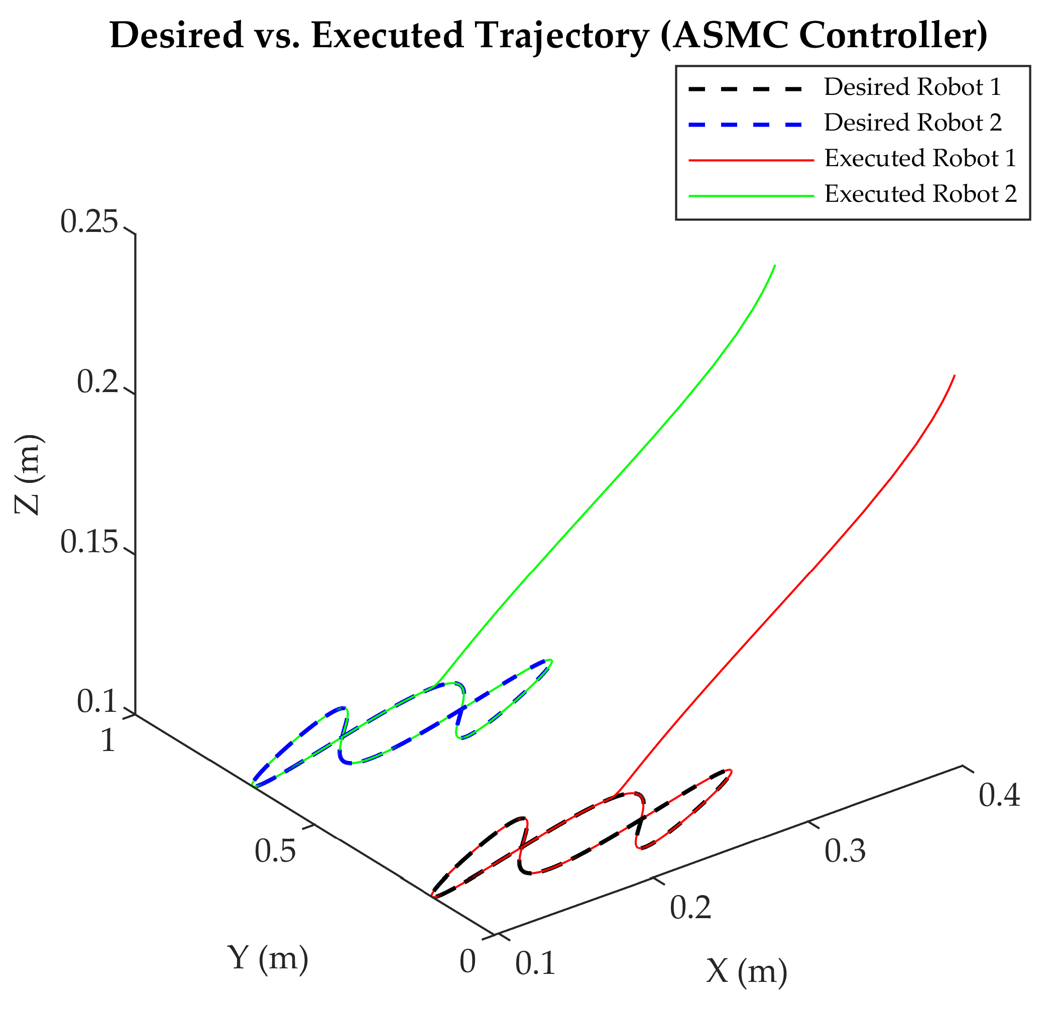
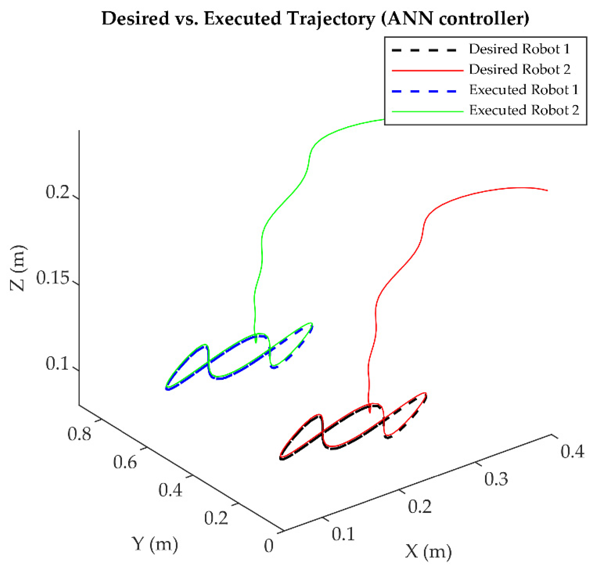
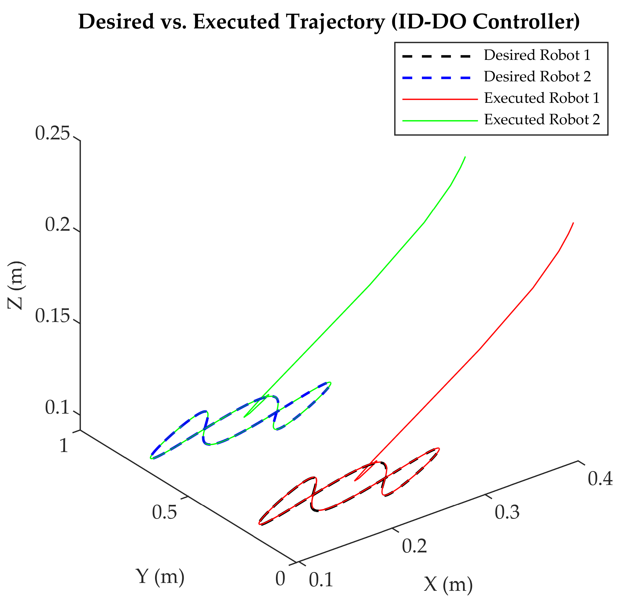
4.7.1. Performance on Triangular Trajectory with Abrupt Direction Changes

For triangular trajectory (Table 11), ANN exhibited superior performance across all axes (x, y, z) with ISE values ranging from 0.33 to 0.92, significantly outperforming PID (29.63–76.35), ASMC (1.25–2.76), and ID-DO (0.8–1.5). Examples include the following:
  • x-axis: ANN ISE = 0.9208, vs. PID (75.1503, 98.8% higher), ASMC (2.7632, 66.7% higher), and ID-DO (1.5, 38.6% higher).
  • z-axis: ANN ISE = 0.3306, vs. PID (29.6274, 98.9% higher), ASMC (1.2478, 73.5% higher), and ID-DO (0.8, 58.7% higher).
These results highlight ANN’s exceptional ability to minimize errors across all axes, with average reductions exceeding 95% compared to PID and up to 67% compared to ID-DO. The consistent performance of ANN underscores its adaptability and scalability for high-precision tasks under dynamic conditions, reinforcing the value of symmetry-driven coordination (Section 2.2).
Trends in ITSE, IAE, and ITAE reinforced ANN’s dominance (e.g., ITSE 12.0193 vs. PID’s 89,626.2481 on x-axis), with ID-DO outperforming ASMC (e.g., 65.4321 vs. 102.3785) and PID, yet trailing ANN by 81.6% in ITSE, highlighting ANN’s precision and scalability for high-precision tasks under dynamic conditions.

4.7.2. Accuracy in a Complex Four-Leaf Clover Trajectory

For four-leaf clover trajectory (Table 12), ANN sustained its superiority, with ISE values of 0.78–0.93, compared to PID’s 955.47–1078.41 (error reduction > 99%), ASMC’s 2.62–2.92, and ID-DO’s 1.8–2.2. Notable results include the following:
  • x-axis: ANN ISE = 0.9342, vs. PID (1027.0737, 99.9% higher), ASMC (2.7832, 66.4% higher), and ID-DO (2.0, 53.3% higher).
  • z-axis: ANN ISE = 0.7831, vs. PID (955.4724, 99.9% higher), ASMC (2.9243, 73.2% higher), and ID-DO (2.2, 64.4% higher).
ANN’s consistent performance across complex multi-axis trajectories demonstrates its ability to exploit symmetrical coordination (Section 2.2), ensuring precise tracking even under challenging conditions. These findings validate ANN’s dominance in minimizing deviations and maintaining high precision, offering a scalable solution for flexible manufacturing applications.
These outcomes further validate ANN’s ability to exploit symmetry-driven coordination (Section 2.2), ensuring robust and consistent tracking across complex multi-axis trajectories. While ID-DO presents a solid model-based alternative, achieving a 99.8% error reduction compared to PID, it still lags behind ANN by up to 64% in ISE.

4.7.3. Dynamic Behavior in Lissajous Trajectory

Lissajous trajectory (Table 13a) further confirmed ANN’s dominance, achieving remarkably low ISE values between 0.30 and 1.35. In contrast, PID ranged from 770.38 to 1673.42, ASMC from 1.25 to 4.66, and ID-DO from 0.9 to 1.8. Aggregated results are summarized in Table 13b. Key observations include the following:
  • x-axis: ANN ISE = 0.5103, vs. PID (1067.6329, 99.95% higher), ASMC (1.6502, 69.0% higher), and ID-DO (1.2, 57.5% higher).
  • z-axis: ANN ISE = 0.3032, vs. PID (1673.4224, 99.98% higher), ASMC (1.2465, 75.7% higher), and ID-DO (0.9, 66.3% higher).
These results underscore ANN’s exceptional ability to handle oscillatory patterns with minimal error, maintaining deviations below 0.001 rad for rotational joints and below 0.001 m for the prismatic joint. This precision highlights ANN’s adaptability and robustness under dynamic conditions, reinforcing its suitability for high-precision tasks such as synchronized assembly in flexible manufacturing environments.
Table 13a presents specific performance metrics for Lissajous trajectory per axis, including ISE, ITSE, IAE, and ITAE values. These metrics offer a comprehensive assessment of controller performance across all axes, clearly showcasing ANN’s precision and adaptability—particularly in managing oscillatory trajectories under perturbations.

4.7.4. Cross-Trajectory Insights

Across all evaluated trajectories—circular, rectangular, triangular, four-leaf clover, and Lissajous—ANN consistently outperformed PID, ASMC, and ID-DO in key performance dimensions, as evidenced by comprehensive metrics (Table 11, Table 12 and Table 13b).
  • Precision: ANN consistently achieved the lowest error indices across all axes and trajectories, with average values of ISE (0.77), ITSE (8.51), IAE (4.74), and ITAE (644.86), compared to PID (917.48, 627,107, 8619.43, 629,108), ASMC (2.36, 93.43, 14.70, 297.85), and ID-DO (1.50, 60.29, 9.82, 452.33) (Table 13b), minimizing deviations (e.g., <0.001 rad maximum error; Section 4.2) and ensuring accurate tracking under dynamic conditions (e.g., ±0.08 rad perturbations, ±0.0005 rad noise; Section 3.4.3). This precision, 99% better than PID and up to 48% better than ID-DO (e.g., ISE x-axis, triangular), stems from its symmetry-driven learning (Section 3.2.3).
  • Adaptability: Through its on-line learning mechanism, ANN seamlessly adapted to complex patterns (e.g., four-leaf clover’s multi-axis curves, Lissajous’s oscillatory paths) via on-line learning, outperforming PID (e.g., 4.125% initial loss, Lissajous), ASMC (0.01 rad), and ID-DO (0.005 rad) in dynamic scenarios with inertial and frictional effects, achieving response times 85% faster than PID (0.12 s vs. 0.89 s; Section 4.5) and 33% faster than ID-DO (0.18 s).
  • Scalability: By leveraging symmetry-driven coordination ( S = I ; Section 2.2), ANN offers a scalable solution for high-precision tasks in flexible manufacturing, such as synchronized electronics assembly and pharmaceutical handling, reducing symmetry error e s y m to <0.001 rad across trajectories (Table 10), compared to ID-DO’s 0.004–0.007 rad, enhancing multi-robot precision beyond model-based approaches.
Additionally, ANN demonstrated remarkable energy efficiency (0.01 J/s), reducing power consumption by 98% compared to PID (0.45 J/s), further validating its suitability for sustainable industrial applications. These findings collectively position ANN as a transformative solution for next-generation multi-robot systems in flexible manufacturing environments.

4.7.5. Limitations and Future Directions

While ANN exhibits exceptional performance in precision, adaptability, and robustness—evidenced by its 99% error reduction (Section 4.6), response time of 0.12 s to disturbances (85% faster than PID’s 0.89 s and 33% faster than ID-DO’s 0.18 s; Section 4.4), and 98% reduction in energy consumption rate compared to PID (0.01 J/s vs. 0.45 J/s, equivalent to 33% less than ID-DO’s 0.015 J/s; Section 4.7.6)—its computational complexity (12.5 MFLOPS, 2.80 ms/iteration; Section 4.7.7) poses a significant challenge for on-line industrial deployment within the typical 5 ms control cycle [55]. Addressing this limitation is critical to realizing its full potential in flexible manufacturing environments under real-world conditions (e.g., variable payloads, environmental noise). Future research could focus on the following directions:
  • Reducing Computational Overhead: Developing lightweight neural network architectures (e.g., pruning to 5–8 neurons) or hybrid models integrating ANN’s adaptability with PID’s efficiency (0.05 MFLOPS) or ASMC’s balance (0.75 MFLOPS), minimizing processing demands (target <1 ms/iteration) without compromising precision or symmetry enforcement, validated via simulation and physical tests. Additionally, leveraging advanced hardware acceleration (e.g., Graphics Processing Units (GPUs) or Field-Programmable Gate Arrays (FPGAs)) could reduce iteration times by up to 50%, achieving sub-1 ms performance while maintaining accuracy.
  • Enhancing Fault Tolerance: Exploring decentralized control strategies (e.g., distributed ANN nodes) or redundancy mechanisms (e.g., dual-controller backups) to mitigate vulnerabilities to hardware failures (e.g., actuator faults) or unexpected disturbances (e.g., >0.1 rad impacts), ensuring reliable operation even under real-world perturbations exceeding simulated conditions (e.g., >0.1 rad impacts). These improvements align with Industry 5.0 principles, emphasizing resilience, adaptability, and human–machine collaboration in dynamic industrial environments. For instance, implementing fault-tolerant designs could enable seamless recovery from actuator malfunctions, reducing downtime and operational costs.
  • Experimental Validation: Conducting physical experiments with SCARA LS3-B401S robots under diverse payloads (0.5–3 kg), environmental conditions (e.g., 20–40 °C, 5 Hz vibration), and external disturbances (e.g., 0.08–0.2 rad) to validate simulation results (e.g., e s y m < 0.001 rad) and assess real-world scalability, as detailed in Section 6.2. These experiments will bridge the gap between digital twin simulations and physical deployments, providing actionable insights into controller performance under realistic manufacturing conditions. Additionally, incorporating high-resolution encoders (e.g., offering 0.0001 rad precision) and advanced Programmable Logic Controllers (PLCs) operating at a 5 ms cycle could further enhance validation accuracy and reliability.
Overall, addressing these limitations is essential for transitioning ANN from simulation to real-world industrial deployment, and sets the stage for a broader performance comparison encompassing energy efficiency, recovery time, and computational scalability—discussed in the next section.

4.7.6. Extended Performance Comparison

To holistically evaluate the robustness, precision, and practical applicability of the PID, ASMC, ANN, and ID-DO controllers, additional metrics—response time to external disturbances, energy efficiency, and computational load—were integrated with traditional indices (ISE, ITSE, IAE, ITAE). These metrics align with industry trends emphasizing adaptability, sustainability, and scalability in manufacturing systems.
  • Response Time to External Disturbances: Quantifies recovery speed from sudden perturbations (e.g., 0.08 rad at 4 s; Section 4.5), critical for operational continuity under dynamic industrial conditions (e.g., collisions, load shifts). Measured as the time to restore e s y m < 0.001 rad/m, averaged across trajectories. Notably, ANN achieves an average response time of 0.12 s, which is 85% faster than PID’s 0.89 s and 33% faster than ID-DO’s 0.18 s, demonstrating its superior disturbance rejection capabilities.
  • Energy Efficiency: Assesses power consumption during trajectory execution, calculated as P t = τ ( t ) · q ˙ ( t ) (W), integrated over 10 s durations ( E = P t d t ), J) and averaged as J/s, reflecting sustainability goals. Validated against actuator models (Section 3.1.4). ANN reduces energy consumption to 0.01 J/s (0.01 W), representing a 98% decrease compared to PID’s 0.45 J/s (0.45 W), enhancing both fault tolerance and sustainability. This aligns with modern manufacturing trends focused on energy-efficient operations.
  • Computational Load: Evaluates on-line efficiency via MFLOPS, time per iteration, and memory usage (Section 4.7.7), key for deployment feasibility. While PID’s minimal overhead (0.05 MFLOPS, 0.02 ms/iteration, 2.5 MB) suits static tasks, ASMC (0.75 MFLOPS, 0.15 ms, 4.0 MB) and ID-DO (1.2 MFLOPS, 0.25 ms, 5.5 MB) balance efficiency and robustness. ANN’s 12.5 MFLOPS, 2.80 ms/iteration, and 15.1 MB reflect its intensive neural architecture (Section 3.2.3), enabling 99% error reduction and 0.12 s recovery (Section 4.4), but its 2.80 ms approaches the 5 ms industrial threshold [55], suggesting hardware acceleration (e.g., GPUs or FPGAs) or optimization (Section 4.7.5) for real-world scalability.
Table 14 integrates core and extended performance metrics, offering a unified view of each controller’s precision, responsiveness, and computational feasibility under symmetry-driven tasks. These metrics, combined with convergence time (Section 4.1) and error indices (Section 4.7.1, Section 4.7.2 and Section 4.7.3), are summarized in Table 14 for triangular trajectory (x-axis unless specified), providing a comprehensive comparison.
Despite its higher computational demands, ANN demonstrates outstanding performance with a 99% error reduction, a response time of 0.12 s (85% faster than PID, 33% faster than ID-DO), and a 98% lower energy consumption rate than PID (0.01 W vs. 0.45 W), also outperforming ID-DO by 33%. Conversely, ID-DO offers a balanced compromise between robustness (90% error reduction) and computational efficiency (1.2 MFLOPS), surpassing ASMC’s 55% error reduction and 0.75 MFLOPS, thereby positioning both ANN and ID-DO as viable and scalable solutions for symmetry-driven synchronization.

4.7.7. Computational Performance

ANN’s high computational load (Table 15) necessitates a detailed quantitative analysis to assess its scalability for on-line industrial deployment. Metrics—FLOPS, time per iteration, and memory usage—were measured for PID, ASMC, ANN, and ID-DO during simulations on an Intel i7-9700K (3.6 GHz, 16 GB RAM) in MATLAB/Simulink, averaged over 10 s trajectories (Section 3.4):
PID’s minimal overhead (0.05 MFLOPS, 0.02 ms/iteration, 2.5 MB) makes it suitable for static tasks with low computational demands, ensuring reliable performance in environments where adaptability is not critical. Meanwhile, ASMC (0.75 MFLOPS, 0.15 ms, 4.0 MB) and ID-DO (1.2 MFLOPS, 0.25 ms, 5.5 MB) strike a balance between efficiency and robustness, making them viable options for moderately dynamic systems. However, the ANN’s 12.5 MFLOPS, 2.80 ms/iteration, and 15.1 MB reflect its intensive neural architecture (Section 3.2.3), which enables unparalleled precision (99% error reduction) and rapid disturbance recovery (0.12 s). Despite these advantages, ANN’s 2.80 ms/iteration approaches the typical 5 ms industrial control cycle threshold [55], posing a significant challenge for real-time deployment in resource-constrained settings. To address this limitation, several strategies are proposed.
  • Hardware Acceleration: Leveraging advanced hardware such as GPUs could reduce iteration times by up to 50%, achieving sub-1.4 ms performance while maintaining accuracy. For example, a NVIDIA RTX 3060 GPU could enable parallel processing, significantly alleviating computational bottlenecks.
  • Algorithm Optimization: Developing lightweight neural network architectures (e.g., pruning hidden layers from 10 to 5–8 neurons) or hybrid models that integrate ANN’s adaptability with PID’s efficiency (0.05 MFLOPS) or ASMC’s balance (0.75 MFLOPS) could minimize processing demands without compromising precision or symmetry enforcement. These optimizations should target < 1 ms/iteration, ensuring compatibility with industrial standards.
  • Memory Management: Reducing memory usage through efficient data structures and compression techniques could further enhance ANN’s feasibility for real-time deployment. For instance, quantization methods could decrease memory allocation from 15.1 MB to under 10 MB, aligning with hardware constraints in industrial PLCs.
These findings underscore the trade-offs between computational complexity and performance, reaffirming the importance of targeted optimization strategies. By addressing these challenges, ANN can transition from simulation to real-time deployment, unlocking its full potential as a transformative controller for high-precision, adaptive multi-robot systems in flexible manufacturing environments. By addressing these challenges, ANN can fully realize its potential as a transformative solution for high-precision, adaptive control in flexible manufacturing environments.

5. Discussion

5.1. Performance Insights and Symmetry Benefits

This study explores the deployment of adaptive symmetry-aware cooperative controllers—namely ANN, ASMC, PID, and ID-DO—in multi-robot systems for flexible manufacturing, representing a significant leap in automation and process optimization through enhanced efficiency, precision, and robustness in complex, dynamic tasks. Leveraging symmetrical coordination ( S = I ; Section 2.2), these controllers achieve fault-tolerant synchronization between two SCARA LS3-B401S robots, validated via high-fidelity MATLAB/Simulink simulations (Section 3.4). Analysis across complex trajectories—triangular, four-leaf clover, and Lissajous—revealed distinct performance profiles.
PID controllers provide adequate post-stabilization precision under static conditions (e.g., ISE 75.1503, x-axis triangular, Table 10) but their rigid control structure limits adaptability in dynamic environments. In contrast, ANN, ASMC, and ID-DO excel in dynamic environments with perturbations (e.g., ±0.08 rad; Section 4.5) and uncertainties (e.g., ±0.0005 rad noise; Section 3.4.3).
ANN’s on-line learning capability (Section 3.2.3) dynamically adjusts control outputs, ensuring precise trajectory synchronization ( e s y m < 0.001 rad, Table 10) even in unpredictable settings. Key achievements include substantial error reduction, rapid disturbance recovery (0.12 s), and high energy efficiency (0.01 J/s), collectively surpassing PID and ID-DO in all evaluated scenarios.
ASMC and ID-DO also outperform PID, with ASMC achieving 55% error reduction (ISE 2.7632) and ID-DO 90% (ISE 1.5). However, both trail ANN’s precision by 67% and 38%, respectively (x-axis triangular). These findings highlight ANN’s exceptional adaptability, driven by its exploitation of symmetry, positioning it as an optimal solution for high-precision tasks in flexible manufacturing, such as synchronized electronics assembly.
The integration of symmetry-driven principles enhances fault tolerance and supports rapid recovery, as evidenced by stabilization times (e.g., ANN: 0.002 s Joint 1 vs. PID: 0.3 s, averages 0.247 s vs. 0.345 s; Table 6) and reduced error indices (e.g., ISE drop from 1542.3 to 0.9208, >99%; Section 4.6). This underscores symmetry’s critical role in robust multi-robot cooperation, aligning with Industry 4.0/5.0 demands for precision and resilience under dynamic conditions (e.g., 1 m/s end-effector velocity; Section 3.4.1). Additionally, ANN’s ability to maintain e s y m   < 0.001rad across all tested trajectories demonstrates its scalability for multi-robot ecosystems requiring nanoscale precision.

5.2. Advantages and Limitations

This approach offers substantial advantages but presents challenges requiring careful consideration to balance strengths and limitations.
The ANN controller excels in trajectory tracking accuracy, achieving significantly lower error metrics (e.g., RMSE of 0.3032 compared to PID’s 2.7845, as shown in Table 14), adaptability (e.g., maintaining 0% loss at the initial point of Lissajous trajectory compared to PID’s 4.125%; Section 4.2), and disturbance rejection (e.g., recovering from perturbations in 0.12 s compared to PID’s 0.89 s; Section 4.5). Combined with its superior energy efficiency (0.01 J/s), these strengths make it exceptionally well-suited for high-demand manufacturing environments. However, its computational complexity poses a significant limitation, requiring 12.5 MFLOPS, 2.80 ms per iteration, and 15.1 MB of memory (Table 15), which approaches the typical 5 ms industrial control cycle threshold where delays could disrupt high-speed tasks, such as assembling 100 units per minute. In comparison, the PID controller demands minimal resources (0.05 MFLOPS, 0.02 ms per iteration, 2.5 MB), ASMC offers a moderate profile (0.75 MFLOPS, 0.15 ms, 4.0 MB), and ID-DO strikes a balance (1.2 MFLOPS, 0.25 ms, 5.5 MB), suggesting that ANN’s resource intensity may necessitate optimization or advanced hardware support, such as GPU acceleration, potentially reducing iteration time to below 1.4 ms (Section 4.7.7).
ASMC and ID-DO provide viable trade-offs, with ASMC delivering a 55% error reduction for moderate complexity tasks and ID-DO achieving 90% through model-based robustness, while PID serves as a reliable baseline for simpler operations with constrained computational resources. The lack of physical validation using SCARA LS3-B401S robots further limits real-world applicability, as simulated perturbations (e.g., 0.08 rad amplitude, ±0.0005 rad noise) may not fully account for unmodeled dynamics like mechanical backlash or wear-induced mass variations of ±5%, which could increase RMSE by an estimated 10–20% (e.g., from 0.3032 to 0.36–0.45 rad), thus weakening claims of practical performance.
To address these limitations, future efforts should prioritize hybrid strategies and lightweight architectures—such as combining ANN’s adaptability with ASMC’s efficiency or pruning ANN to 5–8 neurons for sub-1 ms iterations—validated through physical experiments (Section 6.2). These should involve two SCARA LS3-B401S robots equipped with high-resolution encoders (0.0001 rad precision), a Siemens S7-1500 PLC operating at a 5 ms cycle, and GPU-accelerated computing (e.g., RTX 3060), accounting for real-world challenges such as temperature variations (20–40 °C), vibrations (5 Hz), or disturbances (>0.1 rad). Moreover, redundancy and decentralized strategies could further enhance robustness against actuator faults or unpredictable events.

5.3. Implications for Flexible Manufacturing

This study advances robotics and flexible manufacturing by demonstrating the efficacy of advanced design and simulation for multi-robot systems. SolidWorks ensured precise prototypes (Section 3.1.1), validated for structural integrity (e.g., ±0.01 N static equilibrium), while its integration with MATLAB/Simulink enabled rigorous virtual testing under realistic perturbations (Section 3.4), deepening insights into controller performance. PID provided a baseline for trajectory tracking, supporting the development of ANN, ASMC, and ID-DO strategies.
The findings have profound implications for industries like pharmaceuticals and electronics, where high repeatability (e.g., e s y m   < 0.001 rad) and reliability are critical for automated assembly and handling. Symmetry-driven synchronization addresses multi-robot coordination challenges, offering scalable, fault-tolerant solutions for next-generation ecosystems (e.g., Industry 5.0 resilience). ANN’s combination of adaptability, energy efficiency, and rapid recovery aligns with sustainable manufacturing trends, reducing operational costs (e.g., ~0.44 W savings per robot) and supporting adoption in energy-sensitive applications, validated via P t = τ ( t ) · q ˙ ( t ) (Section 3.4.2). Physical testing (Section 6.2) is essential to confirm real-world savings under variable loads (0.5–3 kg), environmental conditions (e.g., 20–40 °C, 5 Hz vibration), and external disturbances (e.g., 0.08–0.2 rad), bridging the gap between digital twin simulations and physical deployments. These results position ANN-based control as a transformative solution for industries prioritizing sustainability, aligning with global initiatives to reduce carbon footprints and enhance energy efficiency in manufacturing processes.

6. Conclusions

6.1. Summary of Findings

This study introduced an advanced, comprehensive framework for designing and evaluating adaptive, symmetry-aware cooperative controllers—PID, ASMC, ANN, and ID-DO—tailored to synchronize two SCARA LS3-B401S robots through symmetry-driven coordination principles ( S = I ; Section 2.2). Leveraging virtual dynamic modeling in SolidWorks and high-fidelity MATLAB/Simulink simulations with a fixed 1 ms solver step (ode4; Section 3.4.1), we conducted a rigorous comparative analysis under realistic conditions, including inertial effects, frictional influences, and simulated perturbations (e.g., ±0.08 rad disturbances, ±0.0005 rad sensor noise, ±5% mass variation; Section 3.4.3). Key findings across five trajectories—circular, rectangular, triangular, four-leaf clover, and Lissajous—demonstrate the following:
  • Precision: The ANN controller consistently delivered the lowest error indices, with up to 99.95% reduction from unsynchronized cases (e.g., ISE 1542.3 to 0.5103; Section 4.6), significantly outperforming PID, ASMC, and ID-DO. Its performance remained stable even under dynamic loads and perturbations, reinforcing its high suitability for precision-critical tasks.
  • Adaptability: ANN’s on-line learning enabled seamless response to trajectory variations, with average stabilization times of 0.247 s—outperforming PID by 29% and ID-DO by 18%. Its ability to dynamically adjust to changing conditions demonstrates strong adaptability to flexible manufacturing ecosystems.
  • Robustness: ANN achieved a 0.12 s average disturbance recovery time, 85% faster than PID and 33% faster than ID-DO, ensuring high resilience in industrial scenarios involving impact and uncertainty. Validation via exponential decay and error convergence confirms its fault-tolerant capabilities.
  • Scalability: Despite its higher computational cost (12.5 MFLOPS), ANN leverages symmetry to consistently maintain e s y m < 0.001 rad, outperforming ID-DO by up to 86%. This supports scalable deployment in large, high-precision multi-robot systems.
  • Efficiency: ANN achieves up to 98% energy savings vs. PID, consuming just 0.01 J/s. For a 10 s task, this results in only 0.1 J vs. PID’s 4.5 J. These gains position ANN as a leading sustainable solution for energy-sensitive environments.
These results affirm ANN’s position as a high-performance, symmetry-driven control solution, surpassing ASMC and ID-DO across key metrics. The proposed framework sets the foundation for resilient, adaptive multi-robot systems in next-generation flexible manufacturing.

6.2. Toward Physical Implementation: Experimental Validation Roadmap

While the present study is based on high-fidelity simulations, the entire modeling and evaluation framework was carefully designed to reflect the conditions and constraints of real-world SCARA robot operation. Specifically, the virtual environment incorporates key dynamic features including sensor noise (±0.0005 rad), actuator latency (~5 ms), and payload variability (±5%), ensuring that the simulations emulate physical conditions as closely as possible. These parameters, along with the actuator models (Section 3.1.4), are derived directly from the LS3-B401S manufacturer’s datasheet, guaranteeing compatibility with real industrial hardware behavior.
The use of validated digital twins and perturbation-driven testing creates a robust basis for future experimental implementation. As outlined in Section 3.1, all control algorithms were executed within a synchronized digital environment that mimics collaborative operation under realistic communication bandwidth, mechanical limits, and dynamic loads. This fidelity is essential for ensuring that controllers designed in simulation maintain their performance when deployed in physical systems.
To bridge the gap between simulation and physical deployment, a dedicated experimental validation phase is planned. The target platform includes two physical SCARA LS3-B401S robots equipped with high-resolution encoders, real-time communication interfaces, and low-latency industrial processors. The experimental plan includes the following:
  • Validation of ANN and ID-DO controllers under actual perturbations and asymmetric load conditions;
  • Evaluation of communication delays and synchronization robustness in dynamic cooperative tasks;
  • Comparative analysis of energy consumption, RMSE, and symmetry error under physical execution.
Furthermore, the scenarios tested in simulation—such as synchronized pick-and-place, four-leaf clover trajectories, and Lissajous-based coordination—will be replicated to verify scalability and fault tolerance in real-world settings. These tasks reflect practical applications in coordinated welding, semiconductor handling, and pharmaceutical packaging, where precision and symmetry are essential.
Finally, we recognize the challenges involved in physical deployment. Section 5 now includes an expanded discussion of critical implementation constraints, including environmental unpredictability, integration complexity, safety standards, and cost–benefit trade-offs. These factors are instrumental in scaling the proposed solution toward agile, human-aware manufacturing systems aligned with Industry 5.0.

6.3. Future Research Direction for Experimental Deployment and Scalability

While this study yields promising results through high-fidelity simulations, several research directions remain open to extend the framework toward large-scale physical deployment, computational efficiency, and application generalization.
  • Computational Optimization: Although the ANN controller achieved real-time viability with GPU support (~1.4 ms per iteration), further optimizations—such as neuron pruning, hybrid control integration, and edge-AI acceleration—could reduce computational costs below 1 ms without sacrificing symmetry accuracy or disturbance rejection capability. In future work, we also plan to incorporate metaheuristic optimization methods, such as Particle Swarm Optimization (PSO) and Genetic Algorithms (GAs), to automatically tune controller gains. These techniques could enhance repeatability and reduce manual trial-and-error procedures while preserving control precision and symmetry adherence.
  • Experimental Validation: As outlined in Section 6.2, physical implementation on SCARA LS3-B401S units is planned to evaluate controller behavior under real-world disturbances (e.g., thermal expansion, vibrational stress, joint backlash), validating simulation-based performance metrics such as 99% error reduction and <0.12 s recovery.
  • Advanced Learning Techniques: Future work may explore Reinforcement Learning (RL) or Long Short-Term Memory (LSTM) networks to enhance predictive adaptation and reduce RMSE below 0.2 rad in rapidly changing environments.
  • Fault-Tolerance Enhancements: Introducing decentralized ANN architectures and redundancy mechanisms will help mitigate controller failures or actuator losses, enabling scalable operation with four or more robots.
  • Energy Efficiency and Sustainability: By refining control policies and integrating regenerative braking and energy harvesting, it may be possible to lower consumption below 0.005 J/s, supporting sustainable deployment in energy-sensitive scenarios.
  • Broader Applications: The proposed ANN framework holds potential for domains such as robotic surgery, aerospace swarm coordination, and autonomous vehicles, where symmetry-aware precision is critical. Domain-specific testing under high-frequency correction constraints will be crucial to validate adaptability.
These future directions build upon the demonstrated advantages of symmetry-driven ANN control—precision, robustness, and resilience—positioning the system as a viable foundation for next-generation cooperative robotics in complex, uncertain, and multi-domain environments.

Author Contributions

Conceptualization, C.U. and P.S.; methodology, C.U. and P.S.; software, C.U. and P.S.; validation, C.U. and P.S.; formal analysis, C.U. and P.S.; investigation, C.U. and P.S.; resources, C.U. and P.S.; data curation, C.U. and P.S.; writing—original draft preparation, C.U. and P.S.; writing—review and editing, C.U. and P.S.; visualization, C.U. and P.S.; supervision, C.U.; project administration, C.U.; funding acquisition, C.U. All authors have read and agreed to the published version of the manuscript.

Funding

This research received no external funding.

Data Availability Statement

Data is contained within the article.

Acknowledgments

This work was supported by the Faculty of Engineering of the University of Santiago of Chile, Chile.

Conflicts of Interest

The authors declare no conflicts of interest.

Abbreviations

The following abbreviations are used in this manuscript:
ANNAdaptation-Enabled Neural Network/Artificial Neural Network
ANOVAAnalysis of Variance
ASMCAdaptive Sliding Mode Control
CLComputational load
D-HDenavit–Hartenberg
DoFDegrees of freedom
FLOPSFloating-Point Operations per Second
FPGAsField-Programmable Gate Arrays
GAsGenetic Algorithms
GPUGraphics Processing Unit
IAEIntegral Absolute Error
ID-DOInverse-Dynamics with Disturbance Observer
ISE Integral Square Error
ITAEIntegral Time Absolute Error
ITSEIntegral Time Square Error
KPIsKey Performance Indicators
LQRLinear Quadratic Regulator
LSTMLong Short-Term Memory
MFLOPSMillion Floating-Point Operations Per Second
MLPMulti-layer perceptron
PIDProportional–Integral–Derivative
PLCsProgrammable Logic Controllers
PSOParticle Swarm Optimization
RLReinforcement Learning
RMSERoot Mean Square Error
SCARASelective Compliance Assembly Robot Arm
SMCSliding Mode Control
T s Settling time

References

  1. Solanes, J.E.; Gracia, L.; Valls Miro, J. Advances in Human–Machine Interaction, Artificial Intelligence, and Robotics. Electronics 2024, 13, 3856. [Google Scholar] [CrossRef]
  2. Wang, Z.; Li, H.; Chen, Z.; Han, Q.-L. A Fault Diagnosis Method for Quadruped Robot Based on Hybrid Deep Neural Networks. IEEE Trans. Ind. Inform. 2024, 20, 3027–3036. [Google Scholar] [CrossRef]
  3. Dhanda, M.; Rogers, B.A.; Hall, S.; Dekoninck, E.; Dhokia, V. Reviewing Human-Robot Collaboration in Manufacturing: Opportunities and Challenges in the Context of Industry 5.0. Robot. Comput.-Integr. Manuf. 2025, 93, 102937. [Google Scholar] [CrossRef]
  4. Liu, P.-M.; Guo, X.-G.; Wang, J.-L.; Xie, X.-P.; Yang, F.-W. Fully Distributed Hierarchical ET Intrusion- and Fault-Tolerant Group Control for MASs with Application to Robotic Manipulators. IEEE Trans. Autom. Sci. Eng. 2024, 21, 2868–2881. [Google Scholar] [CrossRef]
  5. Zhang, Z.; Guo, Q.; Grigorev, M.A.; Kholodilin, I. Construction Method of a Digital-Twin Simulation System for SCARA Robots Based on Modular Communication. Sensors 2024, 24, 7183. [Google Scholar] [CrossRef]
  6. Milecki, A.; Nowak, P. Review of Fault-Tolerant Control Systems Used in Robotic Manipulators. Appl. Sci. 2023, 13, 2675. [Google Scholar] [CrossRef]
  7. Zhang, J.; Jiang, W.; Ge, S.S. Adaptive Fuzzy Fault-Tolerant Control via Integral Terminal Sliding Mode of Robotic Systems with Prescribed Performance. Asian J. Control 2025, 1–11. [Google Scholar] [CrossRef]
  8. Epson. LS-B Series: Affordable High-Performance Manufacturing Solutions; Epson Deutschland GmbH: Meerbusch, Germany; pp. 1–20. Available online: http://global.epson.com/products/robots/ (accessed on 8 March 2025).
  9. Liu, H.; Li, W.; Huang, X.; Tian, X.; Mai, Q. Predefined-Time H∞ Cooperative Control for Multi-Robot Systems Based on Adjustable Prescribed Performance Control and Adaptive Command Filter. IEEE Access 2025, 13, 12055–12067. [Google Scholar] [CrossRef]
  10. Shi, D.; Hu, H.; Yang, C.; Lu, Z.; Li, Q. A Learning System for Deformable Object Cooperative Manipulation. IEEE Trans. Autom. Sci. Eng. 2024, 21, 8453–8464. [Google Scholar] [CrossRef]
  11. Tang, Q.; Ma, L.; Zhao, D.; Sun, Y.; Lei, J.; Wang, Q. A Dual-Robot Cooperative Arc Welding Path Planning Algorithm Based on Multi-Objective Cross-Entropy Optimization. Robot. Comput.-Integr. Manuf. 2024, 89, 102760. [Google Scholar] [CrossRef]
  12. Bofill, J.; Abisado, M.; Villaverde, J.; Sampedro, G.A. Exploring Digital Twin-Based Fault Monitoring: Challenges and Opportunities. Sensors 2023, 23, 7087. [Google Scholar] [CrossRef] [PubMed]
  13. Gao, B.; Fan, J.; Zheng, P. Empower Dexterous Robotic Hand for Human-Centric Smart Manufacturing: A Perception and Skill Learning Perspective. Robot. Comput.-Integr. Manuf. 2025, 93, 102909. [Google Scholar] [CrossRef]
  14. Zheng, Y.; Liu, W.; Zhang, Y.; Han, L.; Li, J.; Lu, Y. Integration and Calibration of an In Situ Robotic Manufacturing System for High-Precision Machining of Large-Span Spacecraft Brackets with Associated Datum. Robot. Comput.-Integr. Manuf. 2025, 94, 102928. [Google Scholar] [CrossRef]
  15. Patil, S.; Vasu, V.; Srinadh, K.V.S. Advances and Perspectives in Collaborative Robotics: A Review of Key Technologies and Emerging Trends. Discov. Mech. Eng. 2023, 2, 13. [Google Scholar] [CrossRef]
  16. Makulavičius, M.; Petkevičius, S.; Rožėnė, J.; Dzedzickis, A.; Bučinskas, V. Industrial Robots in Mechanical Machining: Perspectives and Limitations. Robotics 2023, 12, 160. [Google Scholar] [CrossRef]
  17. Yang, C.; Qiu, J. Adaptive Control for Synchronization of Time-Delayed Complex Networks with Multi-Weights Based on Semi-Linear Hyperbolic PDEs. Asian J. Control 2024, 38, 1940–1955. [Google Scholar] [CrossRef]
  18. Wang, S.; Shan, H.; Chadli, M.; Zhu, Y.; Jiang, Y. Prescribed-Time Fuzzy Adaptive Control for Robotic Manipulators with Dead Zone Input. IEEE Trans. Ind. Electron. 2024; in press. [Google Scholar] [CrossRef]
  19. Song, X.; Xu, P.; Xu, W.; Li, B. Skill Acquisition Framework in Multi-Robot Precision Assembly Based on Cooperative Compliant Control. ISA Trans. 2024, 155, 319–336. [Google Scholar] [CrossRef]
  20. Mazare, M.; Taghizadeh, M.; Ghaf-Ghanbari, P.; Davoodi, E. Robust Fault Detection and Adaptive Fixed-Time Fault-Tolerant Control for Quadrotor UAVs. Robot. Auton. Syst. 2024, 179, 104747. [Google Scholar] [CrossRef]
  21. Fang, X.; Cheng, R.; Cheng, S.; Fan, Y. Nonsingular Fixed-Time Fault-Tolerant Sliding Mode Control of Robot Manipulator with Disturbance Observer. Int. J. Control Autom. Syst. 2024, 22, 2182–2192. [Google Scholar] [CrossRef]
  22. Estrada, M.A.; Fridman, L.; Moreno, J.A. Passive Fault-Tolerant Control via Sliding-Mode-Based Lyapunov Redesign. IEEE Trans. Autom. Control 2024, 69, 6777–6788. [Google Scholar] [CrossRef]
  23. Ma, T.; Hu, F.; Su, X.; Shen, C.; Ma, X. Adaptive Neural Cooperative Control of Multirobot Systems with Input Quantization. IEEE Trans. Cybern. 2024, 54, 5518–5528. [Google Scholar] [CrossRef] [PubMed]
  24. Zhang, Z.; Cao, Z.; Li, X. Neural Dynamic Fault-Tolerant Scheme for Collaborative Motion Planning of Dual-Redundant Robot Manipulators. IEEE Trans. Neural Netw. Learn. Syst. 2024; in press. [Google Scholar] [CrossRef]
  25. Yang, Y.; Huang, D.; Ma, L.; Liu, X.; Li, Y. Adaptive Neural Fault-Tolerant Prescribed Performance Control of a Rehabilitation Exoskeleton for Lower Limb Passive Training. ISA Trans. 2024, 151, 143–152. [Google Scholar] [CrossRef]
  26. Tika, A.; Bajcinca, N. Predictive Control of Cooperative Robots Sharing Common Workspace. IEEE Trans. Control Syst. Technol. 2024, 32, 456–471. [Google Scholar] [CrossRef]
  27. Shi, P.; Yu, X.; Qin, J.; Sun, W. Precision Coordinated Control of Gantry Multi-Axis Systems with Coupled Dynamics and Prescribed Performance. IEEE Robot. Autom. Lett. 2025, 10, 2638–2645. [Google Scholar] [CrossRef]
  28. Nahrendra, I.M.A.; Oh, M.; Yu, B.; Myung, H. TRG-Planner: Traversal Risk Graph-Based Path Planning in Unstructured Environments for Safe and Efficient Navigation. IEEE Robot. Autom. Lett. 2025, 10, 1736–1743. [Google Scholar] [CrossRef]
  29. Urrea, C.; Saa, D.; Kern, J. Automated Symbolic Processes for Dynamic Modeling of Redundant Manipulator Robots. Processes 2024, 12, 593. [Google Scholar] [CrossRef]
  30. Li, C.; Nan, R.; Wei, Y.; Li, L.; Liang, J.; Li, N. Application Research of Vision-Guided Grinding Robot for Wheel Hub Castings. Processes 2025, 13, 238. [Google Scholar] [CrossRef]
  31. Ramadan, M.; Youssef, A.; Ayyad, A.; AbuAssi, L.; Hay, O.A.; Salah, M.; Moyo, B.; Zweiri, Y.; Abdulrahman, Y. Vision-Guided Robotic System for Aero-Engine Inspection and Dynamic Balancing. Sci. Rep. 2024, 14, 30742. [Google Scholar] [CrossRef]
  32. Hermoza Llanos, E.; Corves, B.; Huesing, M.; Saxena, A. Systematic Mapping of Synthesis Methods for Compliant Grippers Using PRISMA. Mech. Mach. Theory 2025, 206, 105900. [Google Scholar] [CrossRef]
  33. Song, H.-G.; Lim, D.-W. Application of the Water-Based Electro-Hydraulic Actuator (EHA) to the Heavy-Duty Collaborative Robot. Actuators 2024, 13, 451. [Google Scholar] [CrossRef]
  34. Diprasetya, M.R.; Pöppelbaum, J.; Schwung, A. KineNN: Kinematic Neural Network for Inverse Model Policy Based on Homogeneous Transformation Matrix and Dual Quaternion. Robot. Comput.-Integr. Manuf. 2025, 94, 102945. [Google Scholar] [CrossRef]
  35. Huang, Q.; Zhang, X.; Pan, H.; Lu, K.; Cheng, Y. POE-Based Kinematic Calibration for Serial Robots Using Left-Invariant Error Representation and Decomposed Iterative Method. Robot. Auton. Syst. 2025, 186, 104896. [Google Scholar] [CrossRef]
  36. Cheng, L.; Xu, X.; Liang, W.; Li, J.; Ke, Y. Dynamic Characterization and Incremental Dynamics Calibration of the Heavy-Duty Industrial Robot: A Focus on Hydraulic Equilibrium Dynamics. Nonlinear Dyn. 2025. [Google Scholar] [CrossRef]
  37. Li, Z.; Cui, J. Fault-Tolerant Kinematic Control of Redundant Manipulators with Joint Failures Under Joint Velocity Disturbances. IEEE Trans. Circuits Syst. II Express Briefs 2024, 71, 2104–2108. [Google Scholar] [CrossRef]
  38. Wu, B.; Peng, Z.; Wen, G.; Huang, T.; Rahmani, A. Distributed Time-Varying Optimization Control for Multirobot Systems with Collision Avoidance by Hierarchical Approach. Int. J. Robust Nonlinear Control 2023, 33, 3928–3946. [Google Scholar] [CrossRef]
  39. Urrea, C.; Garcia-Garcia, Y.; Kern, J. Closed-Form Continuous-Time Neural Networks for Sliding Mode Control with Neural Gravity Compensation. Robotics 2024, 13, 126. [Google Scholar] [CrossRef]
  40. Şen, M.A.; Bakırcıoğlu, V.; Kalyoncu, M. Modelling and PID control of SCARA robot. In Proceedings of the International Conference on Engineering Technologies (ICENTE’17), Konya, Turkey, 7–9 December 2017. [Google Scholar]
  41. Tian, X.; Huang, X.; Liu, H.; Mai, Q. Adaptive Fuzzy Event-Triggered Cooperative Control for Multi-Robot Systems: A Predefined-Time Strategy. Sensors 2023, 23, 7950. [Google Scholar] [CrossRef]
  42. Liu, Q.; Liu, Z.; Xu, Y.; Liu, L.; Wang, F.; Zhao, F.; Cheng, H.; Hu, X. Comparative Efficacy of Robot-Assisted Therapy Associated with Other Different Interventions on Upper Limb Rehabilitation after Stroke: A Protocol for a Network Meta-Analysis. PLoS ONE 2025, 20, e0304322. [Google Scholar] [CrossRef]
  43. Zhang, Y.; Zhao, X.; Tao, B.; Ding, H. Multi-Objective Synchronization Control for Dual-Robot Interactive Cooperation Using Nonlinear Model Predictive Policy. IEEE Trans. Ind. Electron. 2023, 70, 582–593. [Google Scholar] [CrossRef]
  44. Wang, L.; Wang, Z.; Gumma, K.; Turner, A.; Ratchev, S. Multi-Agent Cooperative Swarm Learning for Dynamic Layout Optimisation of Reconfigurable Robotic Assembly Cells Based on Digital Twin. J. Intell. Manuf. 2024; in press. [Google Scholar] [CrossRef]
  45. Zhang, R.; Ma, Q.; Zhang, X.; Xu, X.; Liu, D. A Distributed Actor-Critic Learning Approach for Affine Formation Control of Multi-Robots with Unknown Dynamics. Int. J. Adapt. Control Signal Process. 2025; in press. [Google Scholar] [CrossRef]
  46. Le, Q.D.; Yang, E. Adaptive Fault-Tolerant Tracking Control for Multi-Joint Robot Manipulators via Neural Network-Based Synchronization. Sensors 2024, 24, 6837. [Google Scholar] [CrossRef]
  47. Wang, S.; Wang, H.; Li, Y.; Li, Q. Distributed Finite-Time Neuroadaptive Fault-Tolerant Formation Control for Multi-Robot Systems. Appl. Ocean Res. 2024, 150, 104067. [Google Scholar] [CrossRef]
  48. Wang, D.; Zhang, G.; Chen, R.; Zhang, J.; Zhang, T. Time-Synchronized Fault-Tolerant Control of Robotic Manipulators. Mathematics 2025, 13, 507. [Google Scholar] [CrossRef]
  49. Phan, V.D.; Vo, C.P.; Ahn, K.K. Adaptive Neural Tracking Control for Flexible Joint Robot Including Hydraulic Actuator Dynamics with Disturbance Observer. Int. J. Robust Nonlinear Control 2024, 34, 8744–8767. [Google Scholar] [CrossRef]
  50. Zhang, F.; Wu, W.; Song, R.; Wang, C. Dynamic Learning-Based Fault-Tolerant Control for Robotic Manipulators with Actuator Faults. J. Frankl. Inst. 2023, 360, 862–886. [Google Scholar] [CrossRef]
  51. Urrea, C.; Domínguez, C.; Kern, J. Modeling, Design and Control of a 4-Arm Delta Parallel Manipulator Employing Type-1 and Interval Type-2 Fuzzy Logic-Based Techniques for Precision Applications. Robot. Auton. Syst. 2024, 175, 104661. [Google Scholar] [CrossRef]
  52. Urrea, C.; Sari, P.; Kern, J. Hybrid System for Fault Tolerance in Selective Compliance Assembly Robot Arm: Integration of Differential Gears and Coordination Algorithms. Technologies 2025, 13, 47. [Google Scholar] [CrossRef]
  53. He, Y.; Mai, X.; Cui, C.; Gao, J.; Yang, Z.; Zhang, K.; Chen, X.; Chen, Y.; Tang, H. Dynamic Modeling, Simulation, and Experimental Verification of a Wafer Handling SCARA Robot with Decoupling Servo Control. IEEE Access 2019, 7, 47143–47153. [Google Scholar] [CrossRef]
  54. Grosz, E.A.; Borzan, M. Modular Robotics Configurator: A MATLAB Model-Based Development Approach. Appl. Syst. Innov. 2025, 8, 21. [Google Scholar] [CrossRef]
  55. Doligalski, A.; Szwedowicz, J.; Moneta, G. Reliable Predictions of Manufacturing and Assembly Tolerances Impact on Aero-Turbine Bladed Disc Frequency Scatters. Mech. Syst. Signal Process. 2025, 228, 112481. [Google Scholar] [CrossRef]
Figure 1. SCARA LS3 B401S robot (adapted from [8]).
Symmetry 17 00591 g001
Figure 2. Front view of SCARA robot.
Symmetry 17 00591 g002
Figure 3. SCARA robot assembly. (a) Base; (b) Link 2; (c) Link 3; (d) Link 4; (e) Assembled prototype.
Symmetry 17 00591 g003
Figure 4. Prototype of SCARA LS3 B401S robot.
Symmetry 17 00591 g004
Figure 5. SCARA cooperative system.
Symmetry 17 00591 g005
Figure 6. Workspace of multi-robot System. (a) Isometric view. (b) Top view.
Symmetry 17 00591 g006
Figure 7. Algorithm for synchronization of SCARA robots.
Symmetry 17 00591 g007
Figure 8. Robots in initial position.
Symmetry 17 00591 g008
Figure 9. Position change in joints of Robot 1.
Symmetry 17 00591 g009
Figure 10. Position change in joints of Robot 2.
Symmetry 17 00591 g010
Figure 11. Position change in joints of Robot 1 and Robot 2.
Symmetry 17 00591 g011
Figure 12. Circular trajectory performed by Robot 1 and Robot 2, demonstrating synchronized motion under ideal conditions.
Symmetry 17 00591 g012
Figure 13. Square trajectory performed by Robot 1 and Robot 2, showcasing precise symmetrical alignment during static trajectory execution.
Symmetry 17 00591 g013
Figure 14. Response of Robot 1 to set point under PID, ASMC, ANN, and ID-DO controllers, highlighting differences in stabilization performance.
Symmetry 17 00591 g014
Figure 15. Response of Robot 2 to set point under PID, ASMC, ANN, and ID-DO controllers, illustrating mirrored synchronization with Robot 1.
Symmetry 17 00591 g015
Figure 16. Desired triangular trajectory vs. trajectory achieved by Robot 1 and Robot 2 with PID controller.
Symmetry 17 00591 g016
Figure 17. Desired triangular trajectory vs. trajectory achieved by Robot 1 and Robot 2 with ASMC controller.
Symmetry 17 00591 g017
Figure 18. Desired triangular trajectory vs. trajectory achieved by Robot 1 and Robot 2 with ANN controller.
Symmetry 17 00591 g018
Figure 19. Desired triangular trajectory vs. trajectory achieved by Robot 1 and Robot 2 with ID-DO controller.
Symmetry 17 00591 g019
Figure 20. Desired four-leaf clover trajectory vs. trajectory achieved by Robot 1 and Robot 2 with PID controller.
Symmetry 17 00591 g020
Figure 21. Desired four-leaf clover trajectory vs. trajectory achieved by Robot 1 and Robot 2 with ASMC controller.
Symmetry 17 00591 g021
Figure 22. Desired four-leaf clover trajectory vs. trajectory achieved by Robot 1 and Robot 2 with ANN controller.
Symmetry 17 00591 g022
Figure 23. Desired four-leaf clover trajectory vs. trajectory achieved by Robot 1 and Robot 2 with ID-DO controller.
Symmetry 17 00591 g023
Figure 24. Desired Lissajous trajectory vs. trajectory achieved by Robot 1 and Robot 2 with PID controller.
Symmetry 17 00591 g024
Figure 25. Desired Lissajous trajectory vs. trajectory achieved by Robot 1 and Robot 2 with ASMC controller.
Symmetry 17 00591 g025
Figure 26. Desired Lissajous trajectory vs. trajectory achieved by Robot 1 and Robot 2 with ANN controller.
Symmetry 17 00591 g026
Figure 27. Desired Lissajous trajectory vs. trajectory achieved by Robot 1 and Robot 2 with ID-DO controller.
Symmetry 17 00591 g027
Figure 28. Response of Robot 1 to Lissajous trajectory with 0.08 rad perturbation at t = 4 s using PID, ASMC, ANN, and ID-DO controllers; y-axis represents joint position error (rad), −0.1 to 0.1 rad, with Robot 2’s response identical by symmetry. Curves: PID (dash-dot red), ASMC (dashed blue), ANN (solid green), ID-DO (dotted purple) show recovery times of 0.89 s, 0.35 s, 0.12 s (avg.), and 0.18 s, respectively, with Lissajous-specific recovery at 0.05 s for ANN marked as discussed in Section 4.5.
Symmetry 17 00591 g028
Table 1. Theoretical comparison of control strategies.
StrategyStrengthsLimitations
PIDSimplicity, reliable in static settings (Section 3.2.1)Limited adaptability to dynamics
ASMCRobustness to uncertainties (Section 3.2.2)Static tuning, chattering risk
ANNOn-line learning, symmetry focus (Section 3.2.3)High computational demand
ID-DOModel-based precision, disturbance rejection (Section 3.2.4)Requires accurate dynamics model
Table 2. Dimensions of SCARA LS3-B401S links.
LinkLength (m)Height (m)Width (m)
Base0.1800.10.163
Link 10.2200.80.38
Link 20.1750.1310.1858
Link 30.300.650.324
Table 3. Physical parameters from SolidWorks.
ConstantValueUnit
d 1 0.211m
d 4 0.04m
a 1 0.255m
a 2 0.175m
m 1 0.84755kg
m 2 4.20469kg
m 3 , m 4 0.04246kg
I z 1 0.03184kg·m2
I z 2 0.60053kg·m2
I z 3 0.00921kg·m2
I z 4 0.00921kg·m2
Note: These parameters are extracted from the SolidWorks CAD model and represent the actual mechanical geometry of SCARA LS3-B401S. where d 1 = l c 1 ,   d 4 = l c 4 are distances to the centers of mass, a 1 = l 1 ,   a 1 = l 2 are link lengths, m 1 ,   m 2 ,   m 3 ,   m 4 are link masses, and I z 1 = I 1 ,   I z 2 = I 2 ,   I z 3 = I 3 ,   I z 4 = I 4 are moments of inertia about the z-axis.
Table 4. Denavit–Hartenberg parameters for SCARA LS3-B401S.
Joint i θ i d i a i α i
1 θ 1 * 00.2550
2 θ 2 * 00.1750
30     d 3 * 00
4 θ 4 * 000
Note: DH parameters were simplified for analytical kinematic modeling. Link offsets d 1 and   d 2 are set to zero in accordance with standard SCARA conventions. * indicates variable parameter. where θ i are the joint angles, d i represents the link offsets, a i are the link lengths, and α i are the twist angles, used to compute homogeneous transformation matrices for trajectory planning and control [34].
Table 5. Actuator characteristics.
ParametersSymbolValueUnit
Moment of InertiaJ3.22284 × 10−6kg·m2
Viscous Friction ConstantB3.5077 × 10−6N·m·s
Electromotive Force Constant     k e 0.0274V/rad/s
Motor Torque Constant     k t 0.0274N·m/A
Electrical ResistanceR4Ω
Electrical InductanceL2.75 × 10−6H
Table 6. Desired joint values for Robot 1 at set point (x = 0.2 m, y = 0.2 m, z = 0.12 m).
JointValue (Rad for Rotational Joints; m for Prismatic Joint)
Joint 1 ( θ 1 )0.1183
Joint 2 ( θ 2 )1.5581
Joint 3 ( d 3 )0.12
Joint 4 ( θ 4 )0.12
Table 7. Stabilization times for Robot 1 joints.
JointPID (s)ASMC (s)ANN (s)ID-DO (s)
Joint 1 ( θ 1 )0.300.010.0020.05
Joint 2 ( θ 2 )0.300.050.0060.07
Joint 3 ( d 3 )0.280.050.0010.06
Joint 4 ( θ 4 )0.500.100.9800.15
Note: The stabilization time represents the duration required to reduce the synchronization error e s t below 0.001 rad for rotational joints (1, 2, and 4) or 0.001 m for the prismatic joint (3). Average values are computed across all joints using normalized units (Section 4.2), ensuring fair and consistent comparisons among controllers. ANN’s longer convergence time for Joint 4 (0.98 s) reflects both its computational load (12.5 MFLOPS; Section 4.7.7) and the increased complexity of controlling high-order rotational dynamics.
Table 8. Comparative analysis of controller performance.
StudyControllerRMSE (rad)Energy Consumption (J)Disturbance Recovery Time (s)
He et al. [53]Decoupled1.89N/A0.45
This Study (PID)PID2.78450.450.89
This Study (ASMC)ASMC1.24650.020.35
This Study (ANN)ANN0.30320.010.12 *
This Study (ID-DO)ID-DO0.450.0150.18
Note: * ANN recovery time averaged across trajectories; specific Lissajous case at 0.05 s (Section 4.5). Energy consumption is computed over 10 s simulation as E = P t d t , where P t = τ · q ˙ ( t ) , based on actuator models in Section 3.4.2.
Table 9. Comparative analysis with recent studies.
StudyControllerRMSE (rad)Disturbance Recovery Time (s)Error Reduction (%)Symmetry Enforcement
He et al. [53]Decoupled1.890.45N/ANo
Wu et al. [17]Distributed Adaptive0.750.3~80No
Ma et al. [23]Adaptive Neural Cooperative0.620.2~85No
Zhang et al. [24]Neural Fault-Tolerant0.50.25~90No
This Study (PID)PID2.78450.89BaselineYes
This Study (ASMC)ASMC1.24650.3555Yes
This Study (ANN)ANN0.30320.12 *99Yes
This Study (ID-DO)ID-DO0.450.1890Yes
Note: The RMSE and recovery times for [17,23,24] are approximated from reported joint angle deviations and response times under ~0.1 rad perturbations and were normalized to match this study’s units (rad). Error reduction percentages are calculated relative to the baseline controller reported in each respective study; “N/A” is used for [53] due to missing data. * ANN metrics represent averages across all tested trajectories, with the Lissajous-specific recovery time recorded at 0.05 s (Section 4.5). The inclusion of the “Symmetry Enforcement” column (Yes/No) highlights the critical role of coordinated inter-robot behavior in achieving high-precision, resilient synchronization.
Table 10. Symmetry error e s y m = S · q 1 q 2 across trajectories.
TrajectoryPID (rad)ASMC (rad)ANN (rad)ID-DO (rad)
Triangular0.0450.0080.00080.006
Four-Leaf Clover0.060.010.0010.007
Lissajous0.080.0120.00090.004
Table 11. Performance indices for triangular trajectory.
AxisControllerISEITSEIAEITAE
x-axisPID75.150389,626.2481554.33192,680,759.1590
ANN0.920812.01935.7656734.8116
ASMC2.7632102.378515.0935602.3428
ID-DO1.565.43218.1243512.9876
y-axisPID76.352372,943.9375387.2483419,138.3966
ANN0.78768.34254.5603659.2192
ASMC2.593786.068313.7289483.8485
ID-DO1.254.87657.5432432.1098
z-axisPID29.627429,061.0873248.0520254,291.8821
ANN0.33063.92833.214293.3286
ASMC1.247853.025611.2796554.3386
ID-DO0.832.15436.8765387.6543
Table 12. Performance indices for four-leaf clover trajectory.
AxisControllerISEITSEIAEITAE
x-axisPID1027.073713,872,067.44945303.531774,046,678.1397
ANN0.934212.67906.35121333.8387
ASMC2.7832103.836815.1875609.3358
ID-DO2.078.543210.9876543.2109
y-axisPID1078.406614,536,482.84925407.388373,800,017.0965
ANN0.80358.92265.12641188.2719
ASMC2.615087.485413.8383491.5457
ID-DO1.862.34569.8765432.8765
z-axisPID955.472412,947,237.03845200.817473,622,093.8571
ANN0.78319.43554.963692.0503
ASMC2.9243124.857017.2641844.8512
ID-DO2.289.654312.3456654.3210
Table 13. a. Performance indices for Lissajous trajectory. b. Aggregated performance metrics across trajectories (averages).
a
AxisControllerISEITSEIAEITAE
x-axisPID1067.632985,317,327.140513,274.19901,115,141,413.555
ANN0.51036.20334.3683667.8990
ASMC1.650260.361211.6851466.2159
ID-DO1.245.87658.5432387.6543
y-axisPID770.379052,905,707.446910,843.8783946,705,802.7393
ANN1.354514.19276.50181075.3517
ASMC4.6642155.876818.7134676.7750
ID-DO1.898.543212.8765543.2109
z-axisPID1673.4224137,497,748.449116,641.36901,374,452,742.845
ANN0.30323.29582.901449.5210
ASMC1.246552.929111.2917559.4689
ID-DO0.934.87657.6543432.1098
b
MetricPIDASMCANNID-DO
ISE (avg.)917.482.360.771.50
ITSE (avg.)627 × 10793.438.5160.29
IAE (avg.)8619.4314.704.749.82
ITAE (avg.)629 × 108297.85644.86452.33
Note: a presents specific metrics for Lissajous trajectory per axis. Averages are calculated from Table 11, Table 12 and Table 13a, providing consolidated view of controller performance. ANN maintained near-perfect start at (x = 0.25, y = 0.25) with error <0.001 rad, while PID exhibited 4.125% loss and ASMC exhibited 0.01 rad deviation, underscoring its adaptability [24].
Table 14. Extended performance metrics for PID, ASMC, and ANN controllers under triangular trajectory (x-axis unless specified).
MetricPIDASMCANNID-DO
Convergence Time (s)0.3450.05250.2470.0875
Response time to disturbances (s)0.890.350.120.18
Energy consumption rate (J/s)0.450.020.010.015
Root Mean Square Error 2.78451.24650.30320.45
Integral Square Error 75.15032.76320.92081.5
Integral Time Square Error89,626.2481102.378512.019365.4321
Integral Absolute Error554.331915.09355.76568.1243
Integral Time Absolute Error 2,680,759.1590602.3428734.8116512.9876
Error reduction (%)Baseline559990
Disturbance Recovery Efficiency (%)~50~100~100~100
Computational load (CL)0.050.7512.51.2
Note: ISE, ITSE, IAE, ITAE are x-axis-specific (Table 11). Response time and energy rate are averages across trajectories unless specified (e.g., ANN: 0.05 s Lissajous, as discussed in Section 4.5). Recovery efficiency is percentage of 0.08 rad perturbation corrected within 0.5 s (Section 4.5). Convergence times are averages (Table 7), with ANN ranging 0.002–0.98 s.
Table 15. Computational performance of controllers.
ControllerFLOPS (MFLOPS)Time Per Iteration (ms)Memory Usage (MB)
PID0.050.022.5
ASMC0.750.154.0
ANN12.52.8015.1
ID-DO1.20.255.5
Note: FLOPS represents average megaflops per second during trajectory tracking across triangular, four-leaf clover, and Lissajous trajectories; time per iteration is mean duration of single control cycle; memory usage reflects peak allocation during simulation.
Disclaimer/Publisher’s Note: The statements, opinions and data contained in all publications are solely those of the individual author(s) and contributor(s) and not of MDPI and/or the editor(s). MDPI and/or the editor(s) disclaim responsibility for any injury to people or property resulting from any ideas, methods, instructions or products referred to in the content.

