Article

Selection of Optimal Intensity Measures and Seismic Fragility Analysis of Prefabricated Rectangular Subway Stations

by
Miaojun Qin
1,2,
Yong Guo
1,
Feng Shi
1,
Yan-Gang Zhao
3 and
Xiaobin Wang
3,*
1
Guangzhou Municipal Engineering Group Ltd., Guangzhou 510060, China
2
School of Civil Engineering and Transportation, South China University of Technology, Guangzhou 510641, China
3
Key Laboratory of Urban Security and Disaster Engineering of Ministry of Education, Beijing University of Technology, Beijing 100124, China
*
Author to whom correspondence should be addressed.
Symmetry 2025, 17(4), 580; https://doi.org/10.3390/sym17040580
Submission received: 11 March 2025 / Revised: 27 March 2025 / Accepted: 7 April 2025 / Published: 10 April 2025
(This article belongs to the Section Engineering and Materials)

Abstract

:
Seismic risk assessment is pivotal for ensuring the reliability of prefabricated subway stations, where selecting optimal intensity measures (IMs) critically enhances probabilistic seismic demand models and fragility analysis. While peak ground acceleration (PGA) is widely adopted for above-ground structures, its suitability for underground systems remains debated due to distinct dynamic behaviors. This study identifies the most appropriate IMs for soft soil-embedded prefabricated subway stations at varying depths through nonlinear finite element modeling and develops corresponding fragility curves. A soil–structure interaction model was developed to systematically compare seismic responses of shallow-buried, medium-buried, and deep-buried stations under diverse intensities. Incremental dynamic analysis was employed to construct probabilistic demand models, while candidate IMs (PGA, PGV, and vrms) were evaluated using a multi-criteria framework assessing correlation, efficiency, practicality, and proficiency. The results demonstrate that burial depth significantly influences IM selection: PGA performs optimally for shallow depths, peak ground velocity (PGV) excels for medium depths, and root mean square velocity (vrms) proves most effective for deep-buried stations. Based on these optimized IMs, seismic fragility curves were generated, quantifying damage probability characteristics across burial conditions. The study provides a transferable IM selection methodology, advancing seismic risk assessment accuracy for prefabricated underground infrastructure. Through a systematic investigation of the correlation between IM applicability and burial depth, coupled with the development of fragility relationships, this study establishes a robust technical framework for enhancing the seismic performance of subway stations, and provides valuable insights for seismic risk assessment methodologies in underground infrastructure systems.

1. Introduction

The construction of cast-in-situ concrete structures presents multiple technical challenges during the implementation phase, characterized by high process complexity, prolonged construction periods, significant susceptibility to climatic conditions, considerable challenges in structural crack control, and heightened reliance on manual labor. To address the above-mentioned issues and achieve the sustainable development of the ecological environment, prefabricated buildings, with their characteristics of shorter construction periods, high construction efficiency, energy conservation, and environmental friendliness, have witnessed widespread adoption in above-ground structures [1,2]. The advancement of prefabricated underground structures faces significant constraints, primarily stemming from the technical complexities involved in construction processes and the limitations of practical construction conditions, resulting in their current application being largely confined to tunnels with standardized shapes and modest cross-sectional sizes [3,4]. Meanwhile, research and application of prefabricated modular structures have begun in large-scale underground structures, including subway station complexes [5]. As early as the 1960s, prefabricated modular structures were introduced into the construction of underground engineering, such as in the concrete structural lining and tunnel construction of the Rotterdam station in The Netherlands [6], the Olympic station and Minsk station in Russia [7], the Xing Plaza subway station in France [8], the Sendai subway station in Japan, etc. [9].
In alignment with the national strategic objectives of carbon peak and carbon neutrality, China’s construction sector is undergoing a progressive transition towards industrialization, with a particular emphasis on fostering sustainable development and environmental protection. This paradigm shift represents a concerted effort to facilitate the industry’s green transformation, thereby contributing to the realization of dual carbon targets through the systematic implementation of industrialized construction practices. In recent years, prefabricated subway stations have witnessed rapid development in urban rail transit, such as Yuanjiadian Station on Line 2 in Changchun [5], Jinshuiqiao Station on Line 6 in Beijing [10], Wuzhong Road Station on Line 15 in Shanghai, and Longxi Station on Line 16 in Shenzhen [11,12]. Generally, underground structures experience significantly less damage under seismic actions compared to above-ground structures [13,14]. However, subway stations and tunnels still sustain damage in earthquake events, such as in the 2008 Wenchuan earthquake and the 2023 earthquake in Turkey’s Kahramanmaraş province.
The seismic resilience assessment of underground infrastructure, particularly subway stations in metropolitan areas, remains a critical research focus in structural engineering due to its substantial implications for public safety and urban functionality [15]. These subsurface transportation hubs, predominantly situated in densely populated urban centers within seismically vulnerable zones [16], pose unique engineering challenges during post-earthquake rehabilitation and reconstruction processes. The complexity of these challenges arises from the intricate interplay among structural integrity, geological conditions, and urban environmental constraints, making seismic performance evaluation an essential component of modern underground structural design and maintenance protocols.
Seismic safety risk assessment serves as an important basis for structural evaluation reliability. Seismic fragility analysis stands as a pivotal approach for the quantitative assessment of structural seismic risk [17]. The seismic demand model serves as the crucial bridge connecting seismic hazards with structural response behavior, forming an essential part of the seismic fragility analysis framework [18].
A seismic demand model refers to the conditional probability that the specific demand of the subway station structure or component is equal to or exceeds a specific value at the given intensity measure (IM) of seismic excitation. Previous studies have shown that accurate probabilistic seismic demand models and seismic fragility mainly rely on appropriate IMs [19]. IM serves as the process variable linking seismic hazards and structural demand models. An appropriate IM can not only reflect the main parameters of earthquake, especially magnitude and spectrum, but is also able fully consider the randomness of seismic excitation, thereby achieving the goal of accurately predicting structural responses [20].
Recently, researchers have proposed various fragility curves under different conditions for different structures [21], including slope and tunnel structures. Pejovic et al. [22] suggested using IMs that include spectral features or velocity related types for the seismic demand model in high-rise frame structures. For example, by using numerical calculations, detailed research has been conducted on tunnels [23,24]. However, most fragility curves are constructed based on various intensity indicators selected by empirical judgment. For instance, peak ground acceleration (PGA), cumulative absolute velocity (CAV), acceleration spectrum intensity (ASI), etc., are used as IMs in the seismic fragility analysis of tunnel and subway stations structures [25,26]. Meanwhile, Huang et al. considered critical elements impacting the dynamic characteristics of tunnels, such as site condition and burial depth, in the numerical analysis [23]. The study reveals that PGA is the most appropriate IM for shallow-buried conditions, whereas peak ground velocity (PGV) proves to be the optimal IM for medium–deep and deep-buried conditions. Hu [27] studied the effect of burial depth on the seismic fragility of subway tunnels, and their findings indicate that the failure probability of tunnels does not exhibit a monotonic decrease as burial depth increases. In their study aimed at identifying the optimal IM for subway stations, Zhang et al. conducted a comprehensive analysis that concurrently considered both site conditions and burial depth factors. Their results indicate that the pseudo-spectral velocity (PSV) and PGV represent the most effective IMs for burial depth of 4 m [28]. In summary, the burial depth constitutes a critical parameter that significantly influences the predictive accuracy of the probabilistic seismic demand model (PSDM). Current research exhibits significant limitations regarding two critical aspects: (1) the identification of appropriate IMs for the PSDM of prefabricated subway stations across varying burial depths, and (2) the understanding of the fundamental mechanisms through which burial depth influences PSDM performance. Therefore, a systematic investigation into the influence of burial depth on the appropriate IM for the PSDM of a prefabricated subway station represents a crucial research direction.
In view of this, the present study establishes a comprehensive numerical investigation framework, utilizing a three-story, two-span subway station from a specific site as the prototype. The 2D finite element model was established using ABAQUS, which can reflect detailed soil–structure interaction characteristics to analyze the seismic performance of prefabricated rectangular subway stations with various burial depths. This research systematically examines how different burial depths affect the seismic response characteristics of prefabricated rectangular subway stations, with particular focus on three critical aspects: (1) inter-story drift ratios, (2) internal force distributions in the structure, and (3) seismic damage patterns and their progression. Simultaneously, a comprehensive evaluation of 19 widely used IMs was conducted based on four rigorous selection criteria: efficiency, practicality, proficiency, and sufficiency. A flowchart of this study is depicted in Figure 1.

2. Seismic Fragility Analysis and Seismic IM Evaluation

2.1. Seismic Fragility Analysis Theory

The seismic fragility curve serves as a probabilistic representation of structural vulnerability, quantifying the conditional probability of a structural system attaining or surpassing predefined damage states across varying seismic intensity measures. The mathematical formulation for seismic fragility assessment can be expressed through the following Equation (1), which establishes the relationship between ground motion intensity parameters and structural damage probability distributions [29].
F R , I M E D P = P R C I M = E D P = R C i f R r d r
where EDP is the peak engineering demand parameter and R represents the seismic demand, which based on the literature, is commonly modeled following a lognormal distribution, as shown in Equation (2). C represents the structural seismic capacity associated with a specific limit state; f R r represents the probability density function.
P f E D P e d p I M = 1 Φ ln Q R I M E D P / e d p β tot
where Φ · represents the cumulative distribution function (CDF) of the standard normal distribution, Q R I M represents the median value in the seismic demand, and β tot represents the standard deviation that integrates three uncertainty indicators, including three primary sources of uncertainty: structural seismic capacity, fragility model variability, and other relevant factors; the specific expression is as Equation (3):
β tot = β C 2 + β D S 2 + β D 2
where β C indicates the uncertainties in the seismic capacity of underground structures. In this study, a deterministic structural analysis approach was implemented. Therefore, β C = 0; β D S indicates the uncertainty in damage measure, which has been assigned as 0.4 [30], and β D is the logarithmic standard deviation of EDP under given IM conditions, characterizing the variability in seismic fragility modeling, which can be determined through Equation (4):
β D ln e d p i ln Q R I M 2 N 2
where edpi indicates the i-th result of EDP from the nonlinear dynamic analysis and N represents the number of nonlinear dynamic analyses.
The correlation between the structural demand parameter Q R I M E D P and IM can be mathematically represented through a power function relationship, as shown in Equation (5):
Q R I M = a I M b
where parameters a and b represent the corresponding regression coefficients. Equation (5) can also be expressed as a linear relationship in logarithms between structural demand and IM [31]:
ln Q R I M = b ln I M + ln a
Normally, the slope parameter b in Equation (6) represents a crucial metric for evaluating the efficiency of the seismic IM, as it quantitatively characterizes the sensitivity of EDP to incremental changes in seismic intensity. A higher value of b corresponds to a greater practical utility of the selected seismic IM. During the calculation process, traditional evaluations of efficiency and practicality metrics may yield incongruities in the weighting β D and b parameters. By substituting Equation (6) into Equation (2), Equation (7) is obtained
P f E D P e d p I M = 1 Φ ln e d p ln a b ln I M ζ ,   ζ = β D b
where ζ, serving as the modified standard deviation, can be employed as an index to measure proficiency, thereby evaluating the combined effects of efficiency and practicality [32]. From Equation (7), it can be seen that the smaller the value of b, the better the proficiency of IM.

2.2. Damage Measures and Damage States

The selection of damage measure (DM) typically affects the defined damage states, thereby influencing the results of seismic fragility. Based on previous studies [30], this work adopted the maximum inter-story drift ratio (MIDR) as the DM to ensure accuracy. Therefore, five damage states are defined in this paper: no damage, slight damage, moderate damage, extensive damage, and collapse. The detail as shown in Table 1 [33].

3. Finite Element Model

3.1. Prefabricated Rectangular Subway Station Structure

To determine the optimal IM for PSDM of prefabricated subway stations across varying burial depths, this study selects the three-story, two-span prefabricated rectangular subway station as a representative example of an asymmetric structure, as depicted in Figure 2. The external dimensions of the rectangular reinforced concrete subway station are 19.7 m in wide and 22.8 m in height, with side walls at a thickness of 700 mm. The station is assumed to be constructed using open-cut excavation technique, wherein the foundation slab is poured in situ with a specified thickness of 1200 mm. The mid-section columns have dimensions of 800 mm in width and 1200 mm in depth, arranged longitudinally at intervals of 3.5 m. These central columns ascend with effective vertical spans of 4.8 m from the ground level to the first floor, 6.2 m from the first to the second floor, and 4.8 m from the second floor to the top of the structure. The loads considered in the design of subway stations include dead loads such as water pressure and equipment gravity, as well as live loads such as crowd loads and vehicle loads. Specific guidelines can be included in the subway design standards [34,35]. The reinforcement within the subway station’s framework is depicted in Figure 3. Since formwork support is not required, the construction of the upper slab, intermediary slab, and the segment connecting the upper slab to the intermediary beam–column employs a hybrid approach that integrates prefabrication with on-site concrete placement. The top slab and the base slab have an average reinforcement ratio of 1.0%, approximately 0.8% for the side walls, and about 6% for the middle columns. The connection performance between components is improved by setting grooves at the ends. Both the intermediate columns and the side walls use prefabricated components with corbels. The top of the prefabricated central columns is equipped with reserved reinforcement bars, which are connected to the embedded sleeves at the bottom. The top of the side walls is reserved with straight and L-shaped reinforcement bars. The stressed steel bars of the prefabricated walls and prefabricated columns are spliced through the embedded grouting sleeves.

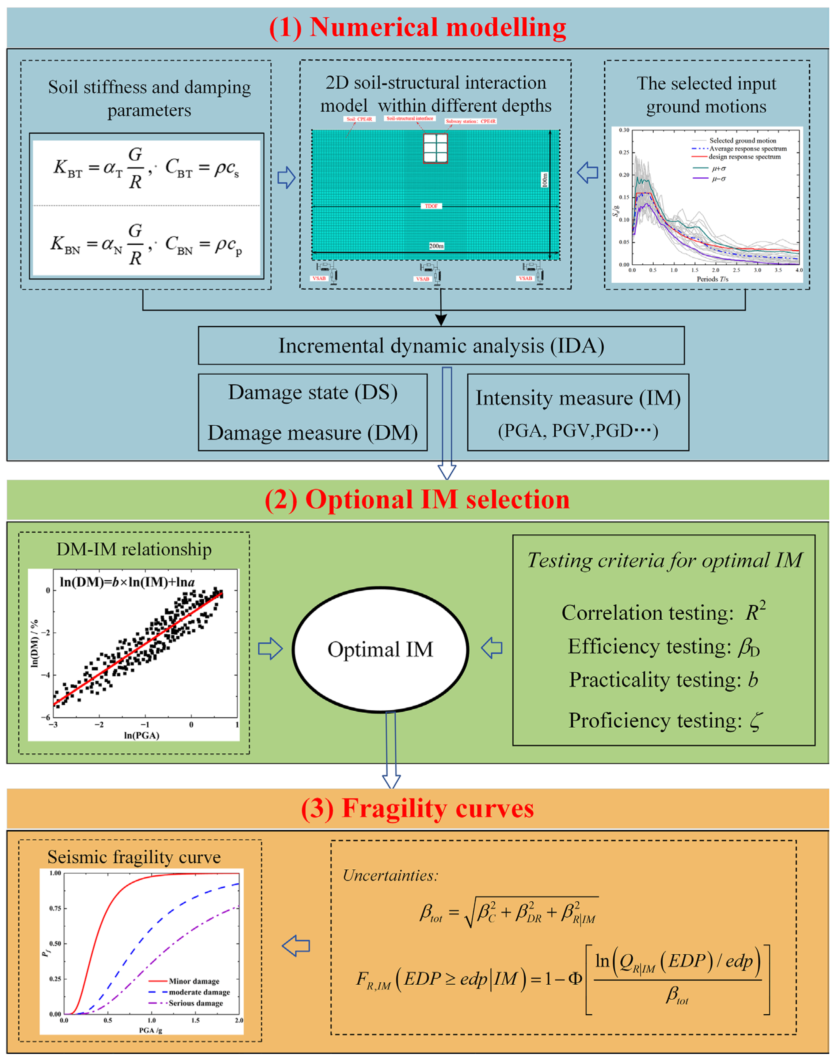
3.2. Establishment of the Overall Model

To account for the soil–structure interaction (SSI), a 2D numerical model of the SSI system for the prefabricated rectangular subway station was constructed using the software ABAQUS (Version 2022), as shown in Figure 4. The lateral extent of the soil domain in the model was established at ten times the width of the station structure, resulting in overall model dimensions of 200 m in width and 100 m in height. The upper boundary of the model corresponds to the ground surface elevation, while the lower boundary is positioned at the bedrock interface. According to the analysis methods in the literature [36], the central column was represented as a wall element with uniform longitudinal section properties using the equivalent bending stiffness approach. This simplification ensures both mechanical accuracy and computational efficiency in the dynamic analysis. Consequently, it is necessary to incorporate a strength reduction factor, and the elastic modulus of the equivalent wall can be quantitatively calculated using Equation (8).
E eq I eq = E c I c L
where EeqIeq denotes the equivalent flexural rigidity per unit length of the wall, EcIc represents the flexural rigidity of the intermediate column, and L denotes the longitudinal spacing between intermediate columns in the prefabricated subway station along its longitudinal axis.
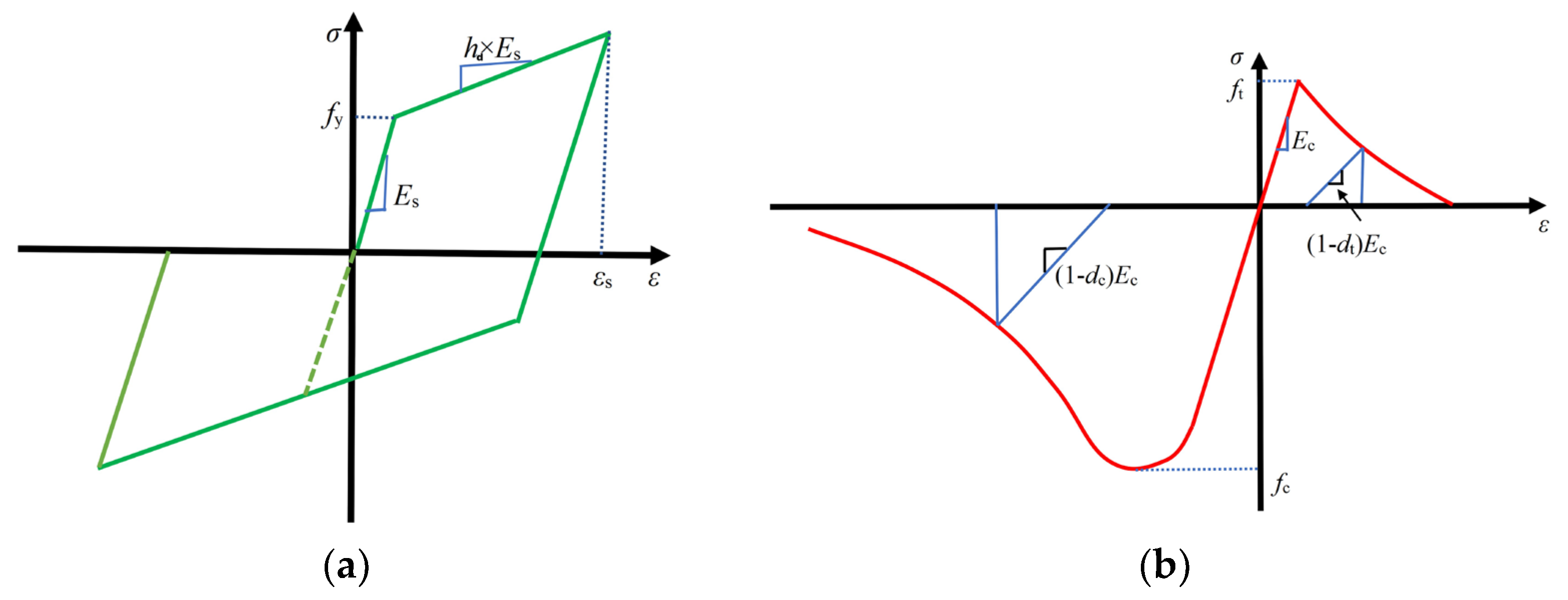
The prefabricated rectangle subway station used C50 concrete. To accurately simulate the progression of damage in concrete under earthquake excitation, this study employs the Concrete Damaged Plasticity Model (CDPM), a framework initially conceptualized by Lubliner et al. [37]. The damage evolution is quantitatively characterized through compression and tensile damage parameters, represented as dc and dt, respectively, as depicted in Figure 5b. The material parameters of reinforcement and concrete are shown in Table 2, Table 3 and Table 4. To guarantee the accuracy of the model, the subway station and the soil adopt the four-node plane strain reduced integration element (CPE4R) from the ABAQUS element library. The reinforcement is modeled using the two-node beam element (B21) and is embedded in the concrete, assuming perfect bonding between the steel bars and the concrete without considering any slip. To ensure the quality of mesh generation, Liao and Liu [38] pointed out that the optimal mesh size for numerical discretization should be determined by Equation (9). Based on the input shear wave velocity Vs of 375.2 m/s and fmax of 15 Hz, the maximum mesh size can be obtained as 2.53 m. Therefore, a maximum mesh size of 2 m can meet the requirements.
h max = 1 75 ~ 1 160 V s / f max
where Vs represents the shear wave velocity of soil layer, which was derived from the relationship G 0 = ρ V s 2 ; fmax represents the maximum frequency of the input.
In accordance with the aforementioned requirements, the model is discretized into a quadrilateral element mesh. For the soil mesh near the subway station, a size of 1 m × 1 m is adopted, whereas the soil mesh further away is 2 m × 2 m, and the mesh size for reinforcement and concrete is 0.2 m. The meshed model is shown in Figure 4.
The connection positions of the prefabricated components are simulated using surface contact to model the transverse and longitudinal connections between the components. The hard contact formulation is implemented in outside contact surface orientations to prevent penetration, while tangential behavior is governed by the Coulomb friction model, with a friction coefficient of 0.8 [39]. Furthermore, the soil–structure interface is idealized to maintain continuous contact during seismic excitation, eliminating any relative sliding or separation. This interaction is modeled using a “surface-to-surface” contact algorithm, with a friction coefficient of 0.4 defined to characterize the interface behavior [40].
To accurately capture the dynamic response of the SSI system subjected to vertically propagating seismic shear waves, kinematic constraints are imposed at equivalent burial depths on both lateral boundaries of the soil domain. This constraint ensures that nodal displacements at corresponding depths on opposite sides of the soil mass remain identical [41]. The viscoelastic artificial boundary (VSAB) is used for realizing the wave absorption and reflection characteristics of a semi-infinite medium. The VSAB formulation exhibits superior frequency stability and effectively simulates the elastic recovery properties of the unbounded domain beyond the truncated boundary, making it a widely adopted and extensively validated approach [42]. The equivalent physical parameters of the VSAB, namely the spring coefficient and damping coefficient, are determined through Equations (10) and (11), respectively.
K BT = α T G R ,   C BT = ρ c s
K BN = α N G R ,   C BN = ρ c p
where KBT and KBN represent the normal and tangential stiffness of the spring, respectively, R is the radial distance from the wave source to the artificial boundary point, cs and cp are the S-wave and P-wave velocities, respectively, G is the shear modulus of the medium and ρ is the mass density of the medium, and αT and αN are the tangential and normal viscoelastic artificial boundary parameters, respectively. According to the reference literature, their values are αT = 1/2 and αN = 1 [42].
In this study, to analyze the seismic response of the subway station SSI system subjected to vertically propagating shear waves, the Translational Degree of Freedom (TDOF) is adopted for the horizontal direction. This constraint represents the coupled motion of nodes on both boundaries of the SSI model at the same burial depth. In the analysis, each step is divided into two parts. First, a static analysis is performed to ascertain the initial stress distribution within the SSI system. Second, a viscoelastic artificial boundary system is established based on the equivalent spring stiffness and damping coefficients derived from Equations (10) and (11), multiplied by the corresponding influence area. Following the method introduced by Du and Zhao [43], the seismic input is converted into a time history representation of equivalent nodal forces applied at the base boundary of the SSI system for subsequent dynamic analysis, as mathematically expressed in Equation (12).
F B = K B u B f f + c B u ˙ B f f + σ B f f n A B
where F B represents the equivalent nodal force on the artificial boundary node, K B and c B represent the equivalent spring stiffness and damping coefficient of the viscoelastic boundary, respectively, u B f f = u , v , w T and u ˙ B f f = u ˙ , v ˙ , w ˙ T represent the displacement and velocity vectors of unrestricted condition of soil at an artificial boundary node, respectively, σ B f f is the stress tensor of the unrestricted condition of soil, A B represents the influence area of the artificial boundary node, and n is the cosine vector of the outer normal direction of the boundary.
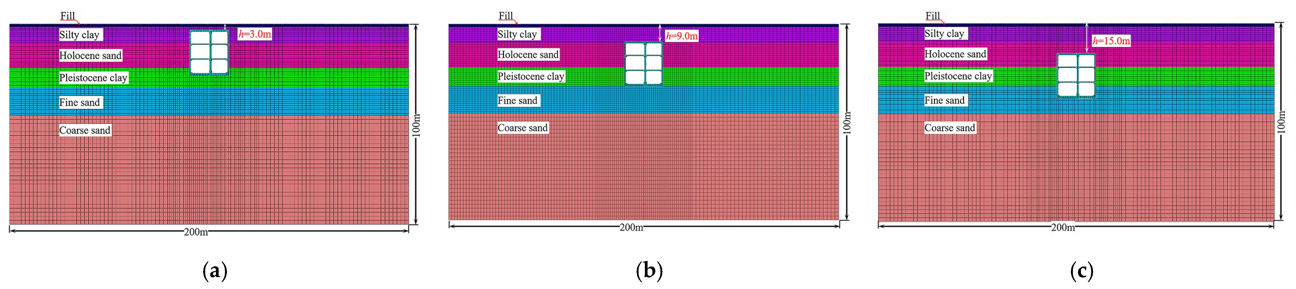
In this study, three different burial depths (3 m, 9 m, and 15 m) are considered, as shown in Figure 6. The geotechnical properties of each soil stratum are detailed in Table 5. To simulate the nonlinear soil response, the numerical code DEEPSOIL [28] was initially employed to perform a 1D seismic response analysis of the soil profile, deriving the equivalent shear modulus under varying horizontal seismic intensities. However, this approach is limited in its capacity to account for the cumulative residual deformation of soil under dynamic loading conditions, and its predictive accuracy may be substantially compromised under strong seismic excitation.
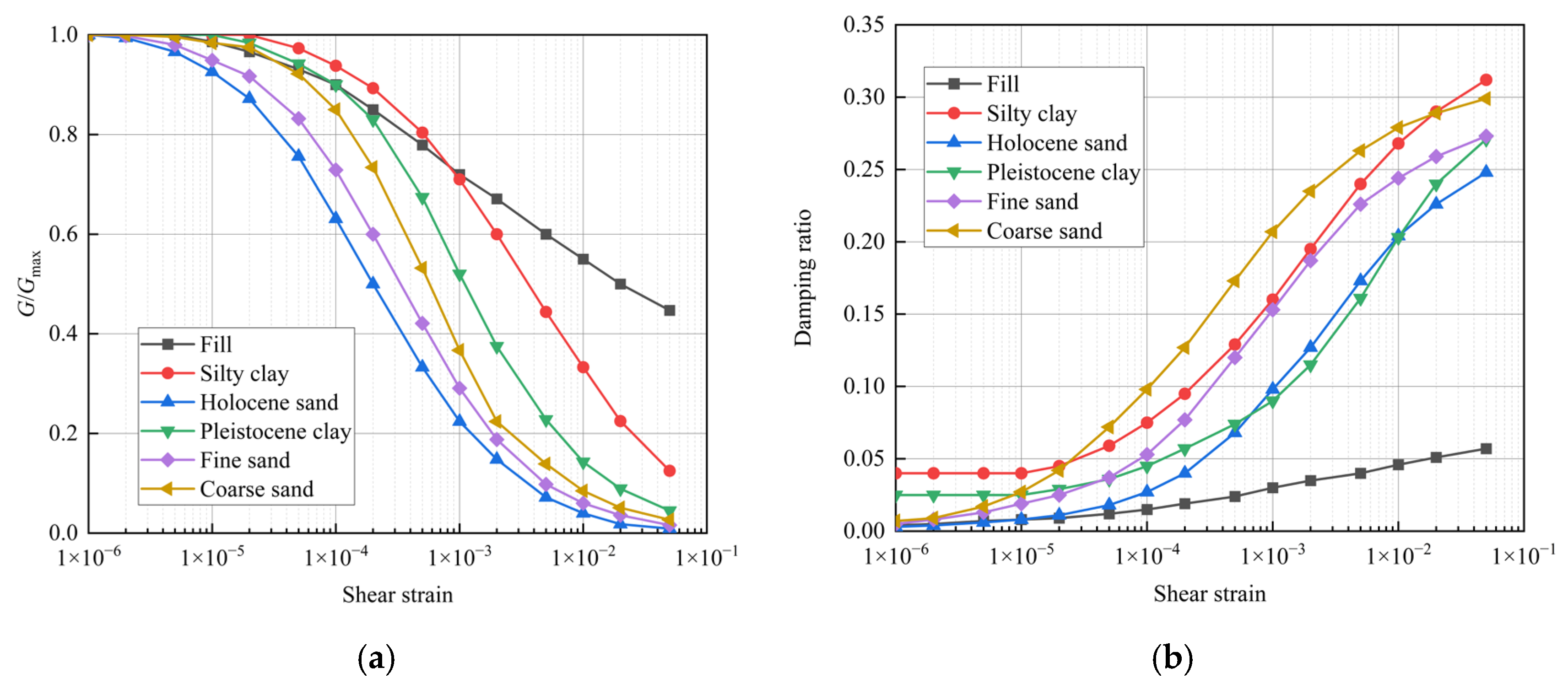
To overcome the aforementioned shortcomings, this study adopts a method that combines the equivalent linearized constitutive model with the Mohr–Coulomb yield criterion [44]. The relationship between the shear modulus G/Gmax, the damping ratio of soil, and shear strain is shown in Figure 7.
In this investigation, the energy dissipation mechanism of soil is characterized through a dual-mechanism damping model, which incorporates two distinct components: (1) hysteretic damping derived from the soil constitutive model, representing the energy loss due to material nonlinearity, and (2) frequency-dependent viscous damping, accounting for the rate-sensitive energy dissipation characteristics [45]. The viscous damping component is formulated using the Rayleigh damping model, whose characteristic parameters can be quantitatively determined through Equation (13):
α β = 2 ζ ω i + ω j ω i ω j 1
where ωi and ωj represent the i-th and j-th natural frequencies, respectively. When selecting two natural frequencies, the frequency range of key concern in the structural analysis should be encompassed. The determination of this frequency band should be comprehensively considered based on factors such as the dynamic behavior of the structure and external loads.

3.3. Selection of Input Ground Motions

The randomness of seismic excitation plays a critical role in affecting structural fragility analysis, and the reasonable selection of seismic records is a prerequisite for ensuring the accuracy of the seismic fragility curves of underground structures. In this study, the 2D model assumes that seismic excitation occurs perpendicular to the station’s longitudinal axis, neglecting 3D field variations along the longitudinal direction. The target response spectrum matching approach was utilized for seismic wave selection [35], complemented by the implementation of the incremental dynamic analysis (IDA) methodology. This technique encompasses a broad spectrum of seismic motion amplitudes, enabling a comprehensive assessment of the structural response under progressively increasing seismic intensities. Empirical studies have demonstrated that the utilization of 10–20 real seismic records is sufficient to effectively capture the influence of seismic motion frequency characteristics. Consequently, this investigation randomly selected 20 seismic records with magnitudes exceeding 6.0 and epicentral distances ranging from 10 to 300 km from the Pacific Earthquake Engineering Research (PEER) database, in accordance with Chinese seismic design code. Table 6 presents a comprehensive summary of the fundamental characteristics of the selected seismic motions. Figure 8 illustrates the acceleration response spectra of the selected seismic records, demonstrating favorable alignment between the average spectrum and the design spectrum. Considering computational efficiency and cost, each input was adjusted to twelve intensity levels, ranging from 0.1 g to 1.2 g in increments of 0.1 g, resulting in 600 conditions across the three burial depths. Here, g represents the acceleration of gravity.

3.4. Structural Damage Assessment Analysis

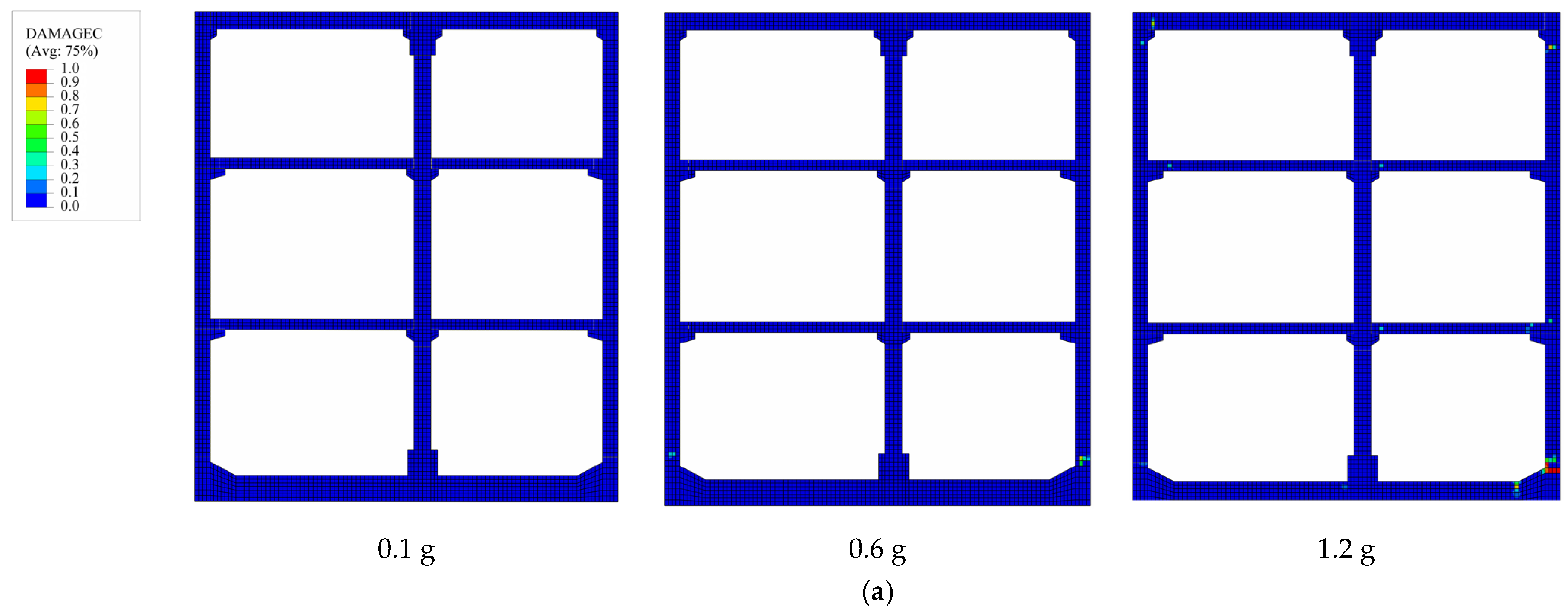
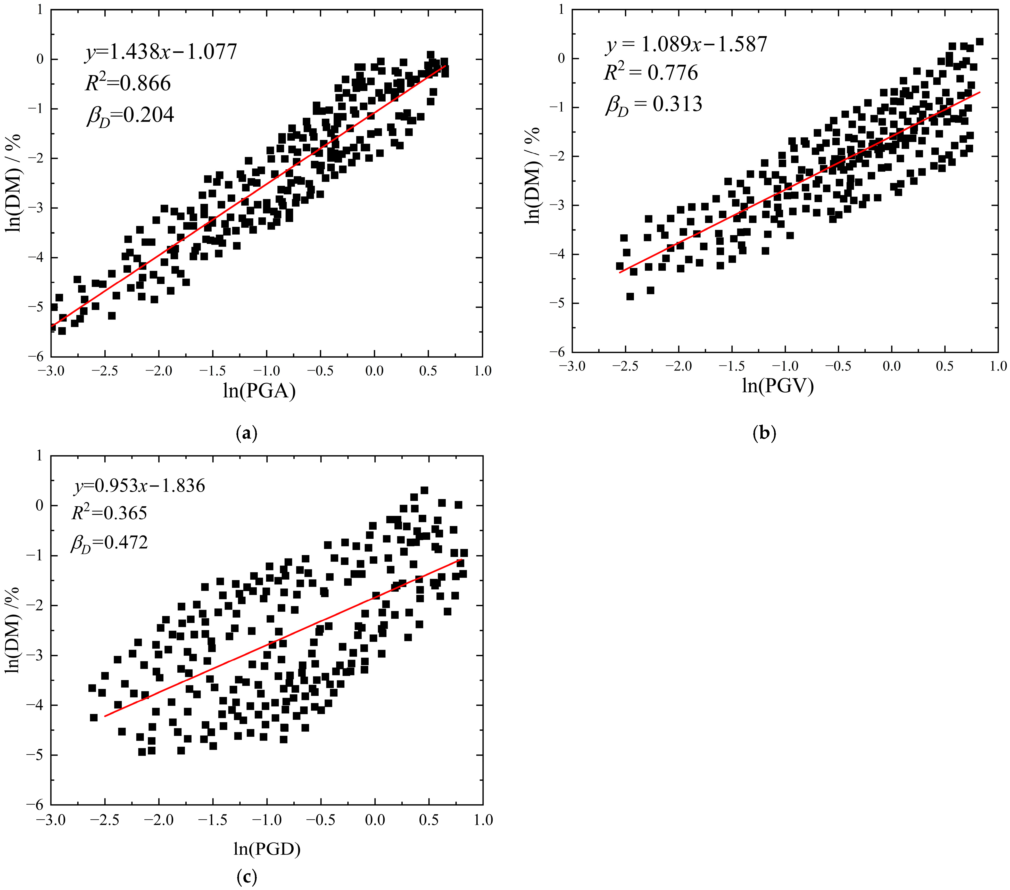
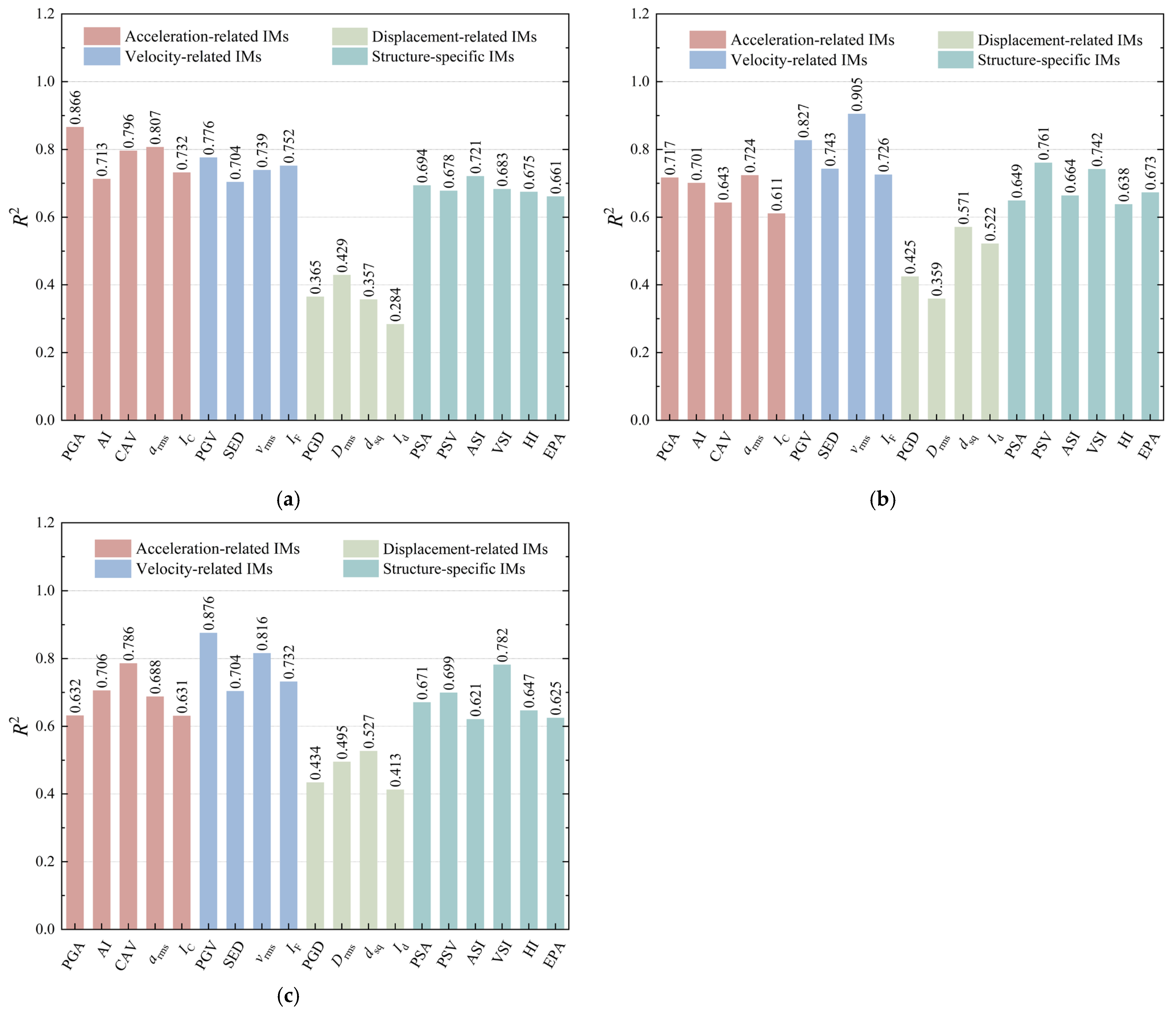
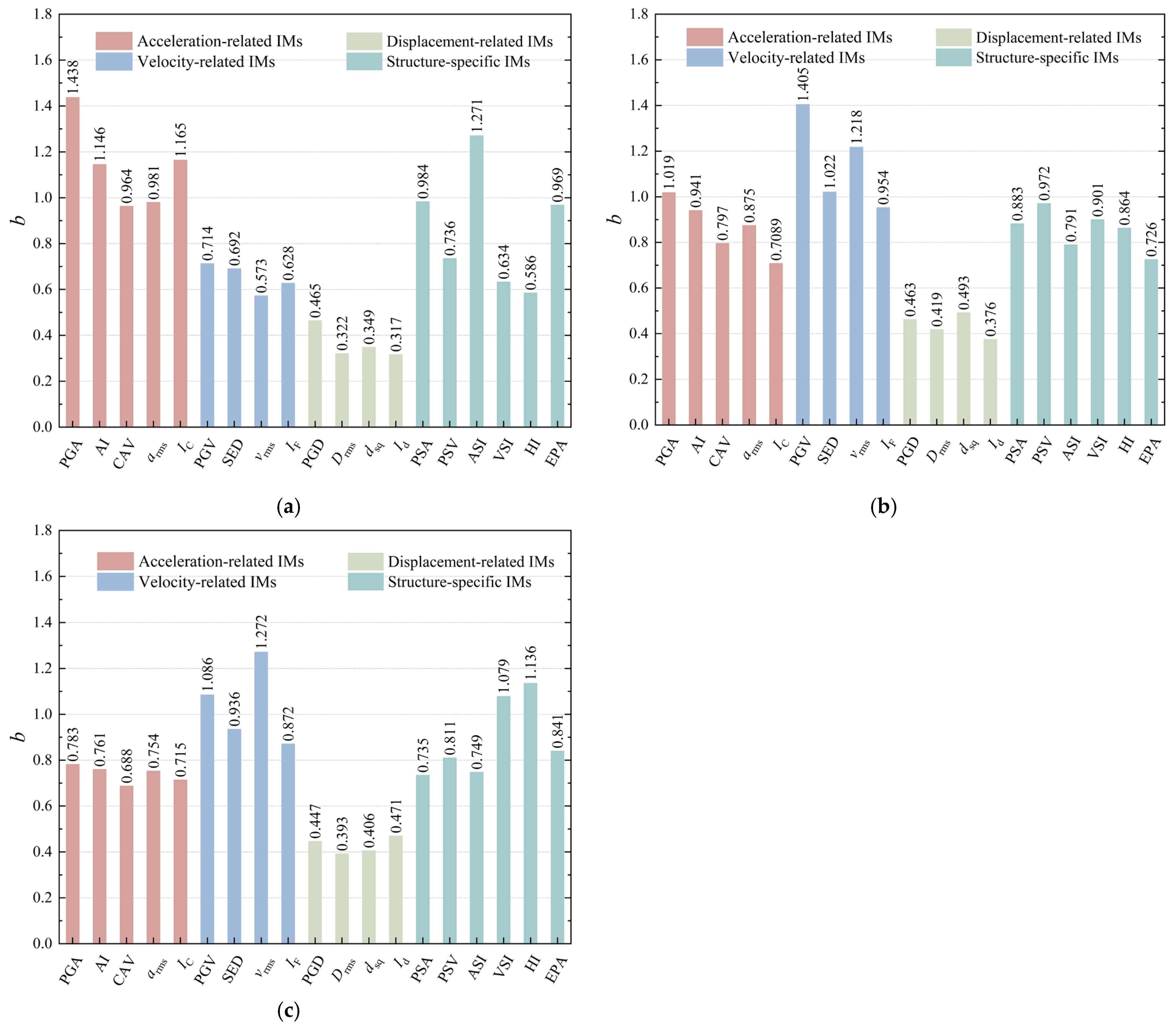
In accordance with the IDA methodology, this study systematically examined and compared the damage progression patterns exhibited by prefabricated subway station structures under three distinct PGA levels of the seismic motion listed in Table 6. The selected PGA levels are 0.1 g, 0.6 g, and 1.2 g. As illustrated in 
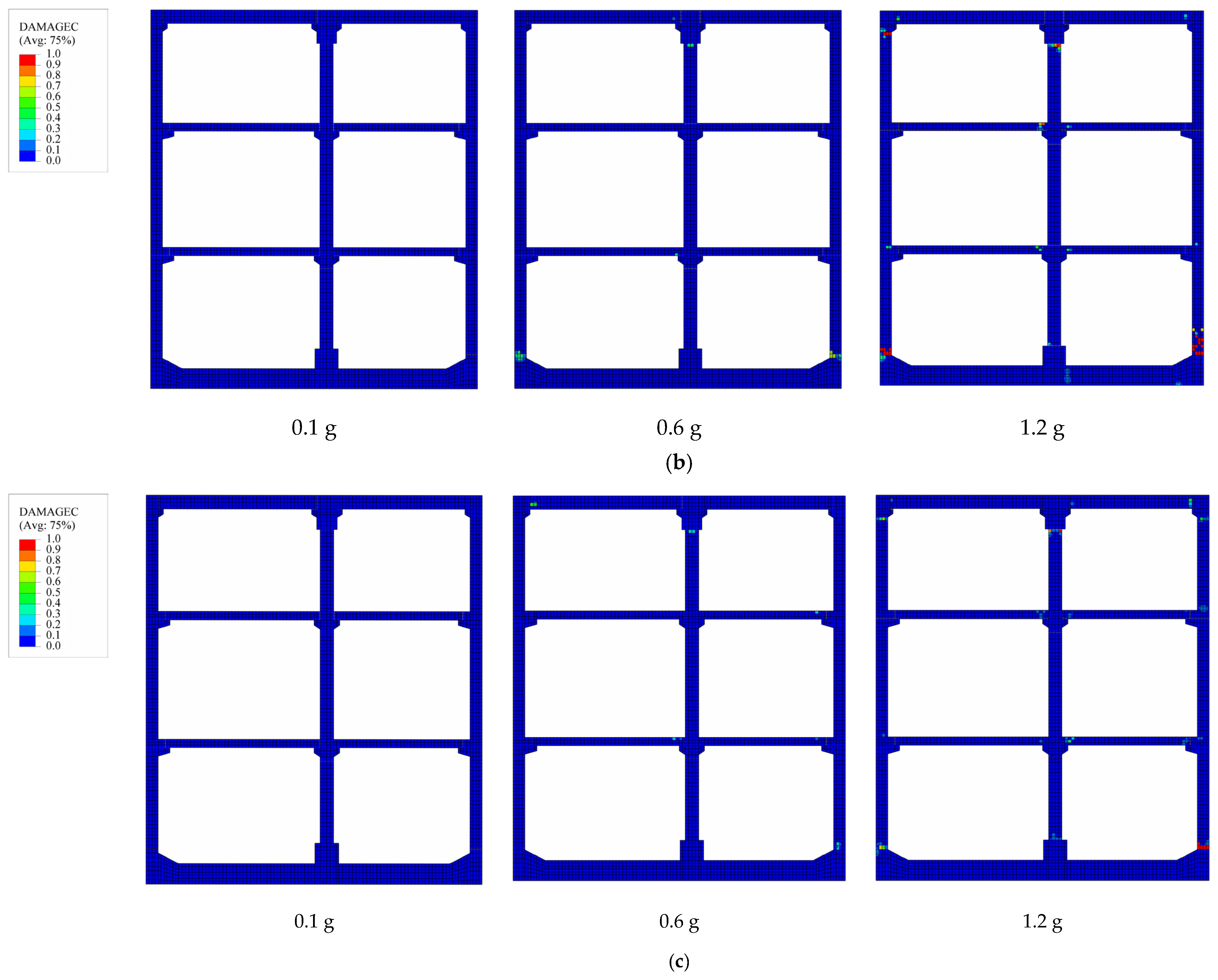
Figure 9, the damage characteristics of prefabricated subway stations with different burial depths are compared under varying PGA levels, using ground motion No. 14 from Table 6 as a representative example. Here, DAMAGEC represents the compressive damage coefficient of concrete. The magnitude of the DAMAGEC parameter is directly proportional to the extent of compressive damage sustained by the structure. DAMAGEC close to 1 signifies the complete degradation of concrete integrity, resulting in loss of load-bearing capacity and structural failure. DAMAGEC close to 0 indicates that structural components remain below the compressive strength threshold of the concrete, maintaining substantial load-bearing capacity.
As demonstrated in Figure 9, prefabricated subway stations at various burial depths show no compressive damage at relatively low PGA levels. This suggests that under seismic conditions with PGA = 0.1 g, the induced stresses in concrete do not exceed the compressive strength threshold, ensuring structural integrity and sufficient load-bearing capacity. As the burial depth increases to 9 m, the DM marginally increases from 0.21% to 0.24%. However, at the maximum investigated depth of 15 m, the DM shows a slight reduction to 0.22%. As the PGA increases, the structure exhibits certain compressive damage. When PGA = 0.6 g, prefabricated subway stations exhibit varying levels of compressive damage depending on their burial depths. The prefabricated subway station with a shallower burial depth exhibits localized damage at the connection interface of the right-side wall base, with damage coefficients ranging from 0.16 to 0.32. Other structural components remain intact without observable damage. The degree of damage in subway station becomes more marked, manifesting at multiple locations with the increase in buried depth. Figure 9b illustrates that for the station with a 9 m burial depth, concrete damage occurs not only at the base of the right-side wall but also in the connection zone between the left floor and the side wall at the apex. The maximum damage coefficient reaches 0.63, accompanied by an increase in the DM from 1.04% to 1.37%. At the maximum investigated burial depth of 15 m, compressive damage is observed at various locations, including the base of the right-side wall and the interface between the top floor middle column and its corbel, with damage coefficients ranging from 0.32 to 0.60. Notably, the DM shows a slight reduction to 1.21% compared to the intermediate burial depth.
When the PGA of the seismic excitation continues to increase, the severity of structural damage also intensifies. As shown in Figure 9a, when the PGA increases from 0.6 g to 1.2 g at a burial depth of 3 m, significant damage occurs at the base of the right-hand side wall, with the damage coefficient reaching 0.91 and the DM reaching 2.68%. The DM demonstrates a positive correlation with burial depth, exhibiting a progressive increase up to 3.89% as the depth extends. However, an interesting deviation from this trend is observed at the burial depth of 15 m, where the DM exhibits a slight reduction to 3.40%. To sum up, under the condition of the same burial depth, the compressive damage to the structure intensifies as the PGA increases. When the burial depth increases, the damaged locations become scattered, and the DM first increases and then decreases. Therefore, the thickness of the overlying soil layer significantly influences the extent of damage to the prefabricated subway station.
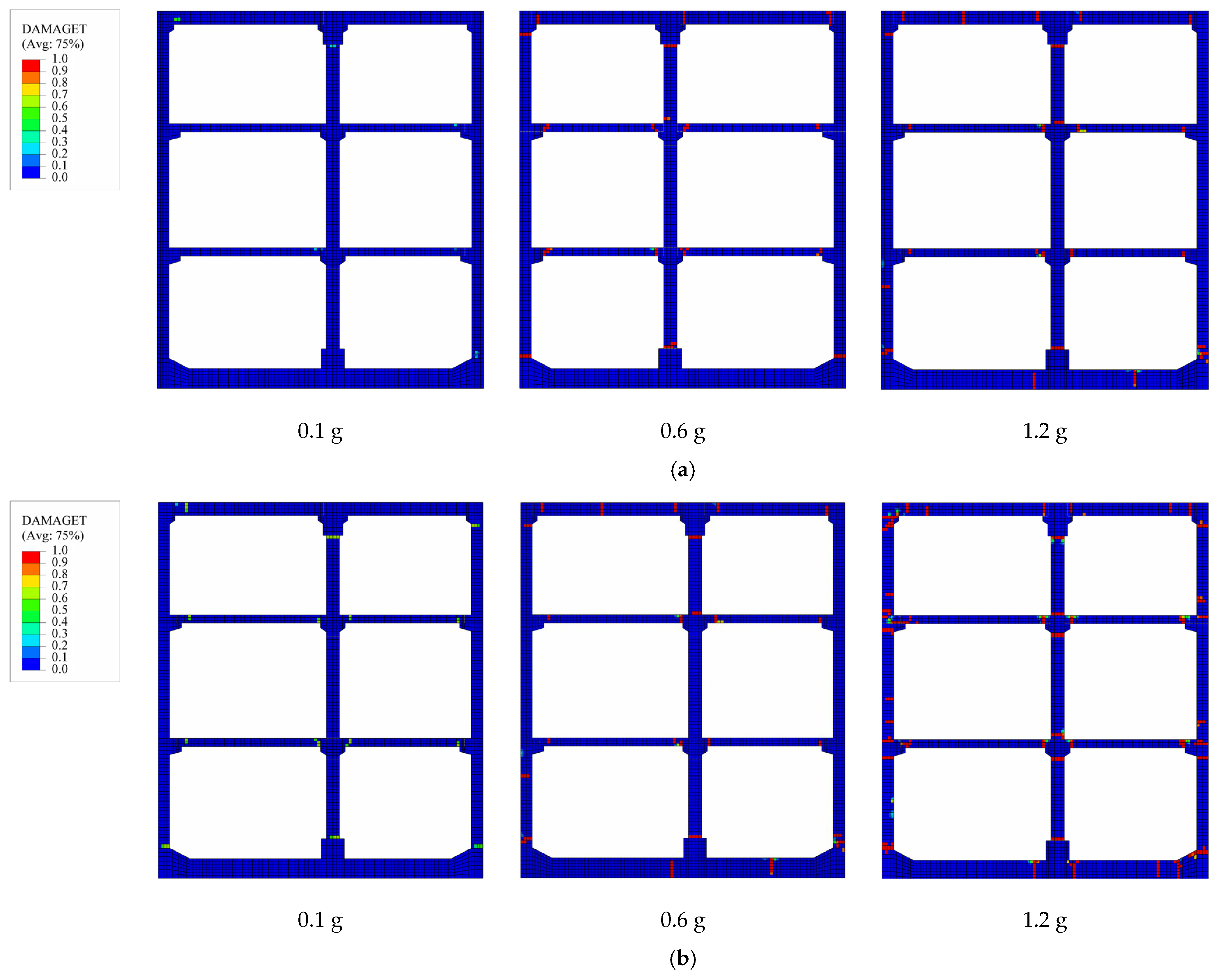
Figure 10 shows the tensile damage of prefabricated subway stations with varying burial depths under the different PGA levels of the No. 14 seismic from Table 6. In this context, DAMAGET denotes the tensile damage coefficient of concrete, where values approaching unity indicate more severe tensile damage in the structure.
As depicted in Figure 10, under low PGA conditions, the shallow-buried prefabricated subway station exhibits no tensile damage. A strong positive correlation exists between burial depth and damage severity, with damage significantly increasing as burial depth increases. At a burial depth of 9 m, slight tensile damage appears at the connection points of various components. When the burial depth increases to 15 m, the extent and severity of damage decrease.
With the escalation of PGA, prefabricated subway stations exhibit varying degrees of tensile damage, which is significantly influenced by their burial depths. At a PGA of 0.6 g, the tensile damage in shallow-buried stations is predominantly localized at critical structural junctions. Furthermore, minor tensile damage is also observed at the bottom-plate area. In contrast, medium-buried stations demonstrate a broader distribution and increased severity of tensile damage. Deep-buried stations, however, show relatively less damage compared to their medium-buried counterparts. Consequently, the medium-buried prefabricated subway stations are identified as the most susceptible to tensile damage under the examined burial conditions. As the PGA increases, prefabricated subway stations exhibit varying degrees of tensile damage, which is significantly influenced by their burial depths. When PGA = 1.2 g, the overall structure of prefabricated subway stations with different burial depths shows extensive damage. Significant structural damage is predominantly observed at the interfacial regions of all components. However, as illustrated in the figure, the medium-buried prefabricated subway station exhibits the most extensive and severe damage in terms of both affected area and intensity compared to other burial depths.
In summary, the overall failure mechanism of prefabricated subway stations under seismic is mainly characterized by the damage at the connection points of various components. The damage to the joints is not caused by compressive damage, but is mainly determined by tensile damage. Meanwhile, the buried depth of prefabricated subway stations significantly affects structural damage. The analysis of damage evolution patterns reveals a consistent nonlinear relationship across varying PGA levels: both compressive and tensile damage demonstrate an initial increase followed by subsequent decrease. The main reason is the influence of soil layer constraints and seismic wave propagation. Furthermore, under intense seismic loading, the initial failure predominantly occurs at the interface between the side wall and the bottom slab, with subsequent damage manifesting at the junction of the side wall and the top slab. Consequently, these critical regions necessitate robust seismic reinforcement measures in structural design. These findings align closely with the empirical observations reported by Xu et al. [30], thereby corroborating the consistency of the results.

4. Intensity Measures and Engineering Demand Parameters

The IM is an important parameter for seismic response analysis and seismic performance evaluation in earthquake engineering. The selection of an optimal IM enables the more precise prediction of structural behavior under seismic loading. However, given the inherent randomness of seismic events and the variability in structural configurations, the applicability of a single IM across diverse scenarios remains limited. Therefore, researchers have proposed multiple seismic IM parameters. To determine the best seismic IM for prefabricated subway stations, this paper evaluates 19 commonly used seismic IMs. Table 7 presents a classification of alternative seismic IMs, which are systematically divided into two distinct categories. The first category comprises IMs that exclusively incorporate seismic characteristics, including those associated with ground motion acceleration, velocity, and displacement. The second category encompasses IMs that integrate structural characteristics, such as those related to acceleration spectra, velocity spectra, and displacement spectra. In the context of this study, an equivalent damping ratio of 5% is assumed. The majority of the scalar IMs considered in this investigation are comprehensively detailed in Huang’s work [23].

5. Optimal IMs and Discussion

To systematically assess the influence of burial depth on IM selection for the seismic performance evaluation of prefabricated subway stations, a comprehensive investigation was conducted across three distinct burial depth configurations. The analytical framework incorporated the aforementioned set of 20 seismic ground motions as input excitations for each burial depth. This approach required performing 240 nonlinear time history analyses on the 2D SSI system, ensuring robust and statistically significant results. The subsequent analysis focuses on identifying optimal IMs through a multi-criteria evaluation framework, encompassing four essential performance metrics: correlation coefficient, efficiency index, practicality assessment, and proficiency measure.

5.1. Correlation Analysis

Correlation analysis was employed to evaluate the linear dependence between the natural logarithmic transformations of IMs and DMs, with the coefficient of determination (R2) serving as a quantitative indicator of model fit quality. The R2 ranging from 0 to 1 provides a statistical measure of the strength of the linear association, where higher values indicate stronger logarithmic relationships between IM and DM variables. Through this analytical framework, IMs demonstrating superior predictive capability are typically characterized by higher R2 values. The results of the regression analysis, as illustrated in Figure 11, reveal the correlation patterns between key IMs and their corresponding DMs for shallow-buried subway station configurations. The graphical representation reveals distinct dispersion patterns among the seismic parameters: PGA has the most concentrated distribution (R2 = 0.866) followed by PGV (R2 = 0.776), while PGD demonstrates the highest data scatter (R2 = 0.365). Furthermore, Figure 12 comprehensively illustrates the correlation analysis results for 19 candidate IMs across three burial depths in prefabricated subway station applications. This comparative analysis provides critical insights into the depth-dependent performance characteristics of various IMs.
As illustrated in Figure 12a, the analysis of shallow-burial prefabricated subway stations reveals a significant correlation between PGA and DM (R2 = 0.866), demonstrating a robust linear relationship. Other IMs, such as arms and CAV, exhibit moderately strong correlations (R2 = 0.807 and 0.796, respectively), though these are lower than that of PGA. Notably, among the evaluated IMs, the intensity measure Id demonstrates the weakest correlation (R2 = 0.284) followed by dsq with an R2 value of 0.357, suggesting limited predictive capability for seismic performance assessment in this context.
Figure 12b illustrates analytical results reveal that vrms, PGV, and PSV emerge as the most effective intensity measures, exhibiting R2 values of 0.905, 0.827, and 0.761, respectively. Figure 12b shows that vrms, PGV, and PSV are the most effective IMs, with R2 values of 0.905, 0.827, and 0.761, respectively. Conversely, Drms, PGD, and Id demonstrate substantially lower predictive capability, with corresponding R2 values of 0.359, 0.425, and 0.522, respectively. These values represent the lowest correlation coefficients observed among all evaluated intensity measures, indicating their limited effectiveness for seismic performance assessment in medium–deep burial conditions. Figure 12c shows the correlation analysis results for deep burial conditions. The results demonstrate a strong correlation between PGV and DM, with the coefficient R2 reaching 0.873, representing the highest value among all analyzed correlations. Moreover, the analysis reveals that two additional IMs, namely vrms and VSI, demonstrate a remarkably strong correlation with the DM, as evidenced by their respective R2 values of 0.816 and 0.782. In contrast, Id demonstrates the smallest correlation with DM among all IMs, with a correlation coefficient of merely 0.413. The correlation coefficients of PGD and Drms are relatively low, at 0.434 and 0.495, respectively. Figure 12 shows that the acceleration-related and velocity-related IMs have stronger correlations with the DM compared to displacement-related IMs.

5.2. Efficiency Analysis

The efficacy of alternative IMs is illustrated in Figure 13. The logarithmic standard deviation βD derived from linear regression serves as a metric for assessing IM effectiveness. A robust IM minimizes the variability in seismic motion analysis, consequently reducing the number of seismic records needed to attain a similar confidence level in the analytical outcomes. The smaller the βD, the lower dispersion in the seismic motion analysis results, suggesting a more effective IM. Conversely, the larger the βD, the worse the IM performance.
β D = i = 1 n ln DM ln a + b ln IM 2 n 2
As illustrated in Figure 13a, the analysis of shallow-buried prefabricated subway station reveals that the PGA exhibits the lowest logarithmic standard deviation (βD = 0.204) among the considered IM. Subsequent evaluation shows that the arms and AI demonstrate slightly higher dispersion values, with βD measurements of 0.211 and 0.216, respectively.
Among the selected IMs, dsq has the largest βD (0.476), indicating its lowest efficiency, followed by PGD and Drms with βD values of 0.306 and 0.364, respectively. For medium-buried prefabricated subway stations, as shown in Figure 13b, PGV is the most effective IM with a βD of 0.169, followed by VSI and SED with βD values of 0.176 and 0.183, respectively. Id exhibits the largest βD (0.466), indicating its lowest efficiency, while Drms and PGD follow with βD values of 0.468 and 0.437, respectively. For deep-buried prefabricated subway stations (Figure 13c), PGV is the most effective IM with a βD of 0.226, followed by vrms and PSV with βD values of 0.237 and 0.261, respectively. PGD has the largest βD (0.488), indicating its lowest efficiency, followed by Drms and another IM with βD values of 0.435 and 0.426, respectively. In summary, velocity-related and acceleration-related IMs generally exhibit stronger correlations with DM than displacement-related IMs, with velocity-related IMs being the most effective.

5.3. Practicality Analysis

Practicality describes the sensitivity of the IM to the DM, usually judged according to the slope b in the fitting results. When the parameter b equals zero, it signifies that the DM maintains a constant value irrespective of variations in the IM, implying that the IM has no measurable effect on the DM and can therefore be disregarded in the analysis. As b increases, the influence of the IM on the DM also increases, making the IM more practical. Figure 14 describes the practicality analysis results of the alternative IMs for prefabricated subway stations under shallow, medium, and deep burial conditions. From Figure 14a, for shallow-buried prefabricated subway stations, the b value of PGA reaches 1.438, making it the most practical IM. ASI and CI demonstrate fitting parameters (b) of 1.271 and 1.165, respectively, indicating relatively lower practical applicability compared to PGA. Notably, Id exhibits the most limited practical utility, with a significantly reduced fitting parameter of b = 0.317. Furthermore, Drms and dsq yield marginally higher b values of 0.322 and 0.349, respectively, categorizing them alongside Id as IMs with substantially reduced practical applicability.
The comparative analysis of IM practicality for medium-buried prefabricated subway stations is presented in Figure 14b. The evaluation results indicate that PGV demonstrates superior practicality with a fitting parameter (b) of 1.405, establishing it as the most effective IM for this structural configuration. Subsequent analysis identifies vrms and SED as secondary practical measures, with respective b values of 1.218 and 1.022. Conversely, the IM exhibiting the lowest practical applicability include Id (b = 0.376), Drms (b = 0.419), and PGD (b = 0.463), which collectively represent the least effective IMs for this specific structural categorization.
Figure 14c illustrates the statistical distribution of fitting parameter (b) values for various IMs applied to deep-buried prefabricated subway stations. The analytical results indicate that vrms achieves optimal performance as an IM, exhibiting a maximum b value of 1.272. The HI and PGV maintain considerable effectiveness, with respective b values of 1.136 and 1.086. Conversely, Drms manifests the lowest practical utility, characterized by a substantially reduced b value of 0.393. This trend is similarly observed in dsq, (b = 0.406) and PGD (b = 0.447), which both demonstrate restricted applicability.
A comprehensive examination of Figure 14 reveals a persistent correlation between IM effectiveness and burial depth characteristics in prefabricated subway stations. The comparative analysis establishes that acceleration-based (e.g., PGA, ASI) and velocity-based (e.g., PGV, vrms) IMs consistently yield higher b parameters than their displacement-based counterparts (e.g., PGD, dsq, Drms). This empirical evidence suggests that acceleration- and velocity-related IMs provide enhanced reliability and practical utility for the seismic assessment of deep-buried prefabricated subway structures, while displacement-related IMs exhibit relatively limited effectiveness in capturing the structural response characteristics.

5.4. Proficiency Analysis

Proficiency represents an integrated performance measure that quantifies the optimal balance between practical applicability and predictive effectiveness in IM selection. This composite indicator was specifically developed to address the inherent limitations of conventional IM selection methodologies, which rely exclusively on unidimensional criteria such as correlation coefficients, efficiency metrics, and practicality parameters. To ensure that the selected IM accurately reflects the actual situation, as proposed by Padgett et al. [46], proficiency can be used to evaluate the IMs, with the proficiency value (ζ) expressed as shown in Equation (7). Figure 15 illustrates the proficiency analysis results of the alternative IMs for prefabricated subway stations under shallow, medium, and deep burial conditions. Figure 15a shows that for shallow-buried prefabricated subway stations, PGA (ζ = 0.142) emerges as the most effective IM, outperforming both AI (ζ = 0.188) and arms (ζ = 0.212). The least proficient IM is Drms, with a ζ value of 1.435, while dsq and Id have ζ values of 1.364 and 1.290, respectively, and are considered less practical IMs.
Figure 15b reflects the proficiency of various IMs for medium-buried prefabricated subway stations. Among these, PGV (ζ = 0.12) demonstrates the highest proficiency, followed by SED (ζ = 0.179) and vrms (ζ = 0.186). Conversely, the least effective IMs are identified as Id (ζ = 1.26), Drms (ζ = 1.12), and PGD (ζ = 0.944).
Figure 15c presents the proficiency measure (ζ) analysis for IMs applied to deep-buried prefabricated subway stations. The evaluation results demonstrate that vrms achieves optimal proficiency, characterized by the lowest ζ value of 0.208. Similarly, PGV and VSI exhibit significant proficiency levels, with corresponding ζ values of 0.208 and 0.273, respectively, indicating their effectiveness as reliable seismic IMs for this structural configuration. In contrast, the least proficient IM is PGD, with a ζ value of 1.09, followed by Drms and dsq, which also show poor proficiency, with corresponding ζ values of 1.08 and 1.07, respectively.
The comparative results presented in Figure 15 reveal a significant pattern: the ζ values associated with acceleration-related and velocity-related IMs for prefabricated subway stations across various burial depths are consistently lower than those of displacement-related IMs. This systematic variation in ζ values demonstrates that both acceleration-related and velocity-related IMs exhibit superior predictive capability compared to displacement-related IMs in the seismic assessment of deep-buried prefabricated subway structures.

5.5. Optimal IM Value Selection

The identification of optimal IMs represents a critical aspect in the accurate seismic performance assessment and safety evaluation of underground structures, particularly prefabricated subway stations. This importance arises from the need to capture essential dynamic characteristics while accounting for the inherent complexity and uncertainty of seismic excitations. Although substantial research efforts have been devoted to establishing optimal IMs for above-ground structures, studies on optimizing IMs for underground structures, especially prefabricated subway stations, remains limited.
Based on the comprehensive analysis above, we have identified and employed three key IMs that demonstrate optimal correlation, computational efficiency, practical applicability, and predictive proficiency. These selected IMs are specifically tailored for the seismic assessment of prefabricated subway stations across varying burial conditions, including shallow, medium, and deep configurations, as systematically illustrated in Figure 16.
Figure 16a indicates that PGA is the optimal IM for shallow-buried prefabricated subway stations, with arms and CAV as viable alternatives. Similarly, Figure 16b reveals that PGV is the most suitable IM for medium-depth buried prefabricated subway stations, with VSI and SED as effective alternatives. As shown in Figure 16c, for deep-buried scenarios, vrms is the most effective IM, followed by PGV and VSI in descending order of effectiveness. For both medium-buried and deep-buried conditions, velocity-related IMs exhibit greater advantages.
In summary, this study concludes that displacement-related IMs demonstrate limited suitability for the conventional seismic fragility analysis of prefabricated underground structures. More importantly, the investigation reveals that burial depth serves as a crucial parameter influencing the selection and optimization of appropriate IMs for the accurate fragility assessment of these structural systems.

6. Establishment of Fragility Curves

The study establishes seismic fragility curves for prefabricated subway stations with varying burial depths using systematic regression analysis. Key IMs corresponding to different damage state thresholds were identified through this analysis. Table 8 presents the median IM values for three distinct damage states (slight, moderate, and extensive) across shallow, medium, and deep burial conditions.
The probabilistic framework employed Equation (3) to calculate the total logarithmic standard deviation (βtot), yielding values of 0.539, 0.526, and 0.552 for shallow, medium, and deep burial depths, respectively. These βtot values were then combined with the characteristic IM parameters in Equation (2) to derive the final fragility functions. Figure 17 demonstrates the resulting fragility curves.
Figure 17 demonstrates the characteristic progression of structural fragility under seismic excitation: (1) The probability of reaching successive damage states exhibits a monotonic escalation with increasing seismic intensity, asymptotically approaching certainty (100% probability) at extreme loading levels. (2) A distinct probabilistic hierarchy emerges across damage severities—at equivalent intensity levels, extensive damage maintains the lowest value of probability, followed by moderate damage, while slight damage dominate the probability distribution.
The developed fragility curves provide a predictive framework for three-story two-span prefabricated subway stations, enabling a quantitative estimation of damage state probabilities across seismic intensity spectra and the data-driven calibration of performance-based seismic design thresholds. Meanwhile, establishing probabilistic correlations between ground motion intensity and structural response advance seismic risk quantification, offering critical insights for the lifecycle management of prefabricated underground structures. This probabilistic framework bridges theoretical seismic analysis with practical engineering applications, enhancing decision-making precision in protecting underground infrastructure against seismic hazards.

7. Conclusions

This study establishes a theoretical foundation for predicting the failure probability of underground prefabricated structures under varying seismic intensities. It advances prefabrication technology in underground engineering and promotes green, low-carbon construction industrialization. Numerical models of prefabricated rectangular subway stations, incorporating soil–structure interaction effects, are developed. The seismic performance of these structures is analyzed using the IDA method. A comprehensive evaluation of 19 selected IMs is conducted based on four key criteria: correlation, efficiency, practicability, and proficiency. Optimal IMs are identified for prefabricated subway stations at shallow, medium, and deep burial depths. Seismic fragility curves for three-span, two-bay prefabricated rectangular subway stations are developed based on PGA, PGV, and vrms. The main conclusions are as follows:
(1) Under seismic action, the compressive damage of prefabricated rectangle subway stations is mainly concentrated at the right bottom slab position, while tensile damage is mostly concentrated at the connection positions of various components. Meanwhile, the analysis results show that as the burial depth increases, the response first strengthens and then weakens.
(2) For shallow-buried conditions, the optimal IM is PGA, followed by arms and CAV. In the case of medium-buried prefabricated subway stations, PGV is the optimal IM, with SED and vrms ranking second and third, respectively. Under deep-buried conditions, vrms emerges as the optimal IM, followed by PGV and VSI.
(3) The analysis of burial depth effects reveals distinct patterns in optimal IM selection for prefabricated rectangle subway stations. Under shallow burial conditions, acceleration-based IMs (e.g., PGA and ASI) demonstrate superior correlation with structural response parameters. Conversely, for medium and deep burial configurations, velocity-related IMs (including PGV and vrms) exhibit enhanced predictive capability for seismic performance evaluation.
(4) Seismic fragility analysis yields critical insights into structural fragility characteristics. The derived fragility curves demonstrate that the probability of occurrence follows a distinct level across damage states: slight damage maintains the highest probability distribution across varying seismic intensities, while extensive damage consistently shows the lowest probability of occurrence. This probabilistic distribution pattern provides valuable quantitative benchmarks for seismic risk assessment and the performance-based design of prefabricated subway station structures.

Author Contributions

Conceptualization, M.Q. and Y.-G.Z.; methodology, M.Q. and F.S.; software, X.W. and M.Q.; validation, M.Q., Y.-G.Z., and X.W.; formal analysis, Y.G.; investigation, M.Q.; resources, F.S.; data curation, M.Q.; writing—original draft preparation, M.Q.; writing—review and editing, X.W. and Y.-G.Z.; visualization, X.W.; supervision, F.S.; project administration, Y.G.; funding acquisition, M.Q. and Y.-G.Z. All authors have read and agreed to the published version of the manuscript.

Funding

This research was funded by Guangzhou Municipal Construction Group Co., Ltd. Science and Technology Plan Project 2024 National Science and Technology Innovation Platform Research Cultivation Fund, grant number [2024]-KJ044 and the National Key R&D Program of China (Nos. 2023YFC3805100, 2023YFC3805101).

Data Availability Statement

The authors confirm that the data supporting the findings of this study are available within the article.

Acknowledgments

We gratefully acknowledge Guanfeng An for his expert guidance on model analysis.

Conflicts of Interest

The authors Miaojun Qin, Yong Guo and Feng Shi were employed by the company Guangzhou Municipal Engineering Group Ltd. The remaining authors declare that the research was conducted in the absence of any commercial or financial relationships that could be construed as a potential conflict of interest.

References

  1. Sah, T.P.; Lacey, A.W.; Hao, H.; Chen, W. Prefabricated Concrete Sandwich and Other Lightweight Wall Panels for Sustainable Building Construction: State-of-the-Art Review. J. Build. Eng. 2024, 89, 109391. [Google Scholar] [CrossRef]
  2. Ma, Z.; Chen, D.; Zhang, J.; Yang, G.; Wang, S.; Sun, X.; Xu, W.; Wang, X. Experimental Research on Seismic Performance of Prefabricated Monolithic Wall Connection of Modular Concrete Structure. Structures 2024, 68, 107202. [Google Scholar] [CrossRef]
  3. Chen, H.; Liang, J.; Li, D.; Ba, Z. Transverse Seismic Analysis Method of Underground Interchange Prefabricated Utility Tunnel. Structures 2024, 68, 107112. [Google Scholar] [CrossRef]
  4. Liang, J.; Zhang, J.; Xu, A.; Dong, B.; Ba, Z. Shaking Table Tests on Transverse Seismic Performance of a New Type of Combined Prefabricated Utility Tunnel. Structures 2024, 69, 107340. [Google Scholar] [CrossRef]
  5. Yang, X.; Lin, F. Research on Prefabricated Metro Station Structure and Key Assembly Technologies. Tunn. Undergr. Space Technol. 2024, 153, 106029. [Google Scholar] [CrossRef]
  6. Mikaeil, R.; Shaffiee Haghshenas, S.; Shirvand, Y.; Valizadeh Hasanluy, M.; Roshanaei, V. Risk Assessment of Geological Hazards in a Tunneling Project Using Harmony Search Algorithm (Case Study: Ardabil-Mianeh Railway Tunnel). Civ. Eng. J. 2016, 2, 546–554. [Google Scholar] [CrossRef]
  7. Luo, Y.; Chen, J.; Huang, P.; Tang, M.; Qiao, X.; Liu, Q. Deformation and Mechanical Model of Temporary Support Sidewall in Tunnel Cutting Partial Section. Tunn. Undergr. Space Technol. 2017, 61, 40–49. [Google Scholar] [CrossRef]
  8. Yang, X.; Lin, F. Prefabrication Technology for Underground Metro Station Structure. Tunn. Undergr. Space Technol. 2021, 108, 103717. [Google Scholar] [CrossRef]
  9. Chen, J.; Xu, C.; Du, X.; Han, R.; El Naggar, H.M. Physical and Numerical Modeling of Seismic Soil-Structure Interaction of Prefabricated Subway Station Structure. Eng. Struct. 2023, 290, 116364. [Google Scholar] [CrossRef]
  10. Chen, J.; Xu, C.; El Naggar, H.M.; Du, X. Quantification of Seismic Performance Index Limits and Evaluation of Seismic Fragility for a New Rectangular Prefabricated Subway Station Structure. Tunn. Undergr. Space Technol. 2023, 138, 105183. [Google Scholar] [CrossRef]
  11. Yang, X. Development Status of and Outlook for Construction Technology for Prefabricated Metro Stations in China. Tunn. Constr. Suidao Jianshe 2021, 41, 1849–1870. [Google Scholar]
  12. Yang, X.; Huang, M.; Lin, F. Research Strategies on New Prefabricated Technology for Underground Metro Stations. Urban Rail Transit 2019, 5, 145–154. [Google Scholar] [CrossRef]
  13. Tsinidis, G. Response Characteristics of Rectangular Tunnels in Soft Soil Subjected to Transversal Ground Shaking. Tunn. Undergr. Space Technol. 2017, 62, 1–22. [Google Scholar] [CrossRef]
  14. Xu, Z.; Du, X.; Xu, C.; Han, R. Numerical Analyses of Seismic Performance of Underground and Aboveground Structures with Friction Pendulum Bearings. Soil Dyn. Earthq. Eng. 2020, 130, 105967. [Google Scholar] [CrossRef]
  15. Wang, W.L.; Wang, T.T.; Su, J.J.; Lin, C.H.; Seng, C.R.; Huang, T.H. Assessment of Damage in Mountain Tunnels Due to the Taiwan Chi-Chi Earthquake. Tunn. Undergr. Space Technol. 2001, 16, 133–150. [Google Scholar] [CrossRef]
  16. Shen, Y.; Gao, B.; Yang, X.; Tao, S. Seismic Damage Mechanism and Dynamic Deformation Characteristic Analysis of Mountain Tunnel after Wenchuan Earthquake. Eng. Geol. 2014, 180, 85–98. [Google Scholar] [CrossRef]
  17. Borgonovo, E.; Zentner, I.; Pellegri, A.; Tarantola, S.; De Rocquigny, E. On the Importance of Uncertain Factors in Seismic Fragility Assessment. Reliab. Eng. Syst. Saf. 2013, 109, 66–76. [Google Scholar] [CrossRef]
  18. Berahman, F.; Behnamfar, F. Probabilistic Seismic Demand Model and Fragility Estimates for Critical Failure Modes of Un-Anchored Steel Storage Tanks in Petroleum Complexes. Probabilistic Eng. Mech. 2009, 24, 527–536. [Google Scholar] [CrossRef]
  19. Zhang, C.; Zhao, M.; Zhong, Z.; Du, X. Optimal Intensity Measures in Probabilistic Seismic Demand Model of Subway Station. Tunn. Undergr. Space Technol. 2023, 142, 105443. [Google Scholar] [CrossRef]
  20. Jiang, J.; Xu, C.; Du, X.; Chen, G.; Xu, Z. Optimal Index of Earthquake Intensity Measures for Seismic Design of Underground Frame Structure of Shallow-Buried Subway Station. Chin. J. Geotech. Eng. 2023, 45, 318–326. [Google Scholar] [CrossRef]
  21. Mazza, F.; Labernarda, R. Structural and Non-structural Intensity Measures for the Assessment of Base-isolated Structures Subjected to Pulse-like Near-fault Earthquakes. Soil Dyn. Earthq. Eng. 2017, 96, 115–127. [Google Scholar] [CrossRef]
  22. Pejovic, J.R.; Serdar, N.N.; Pejovic, R.R. Optimal Intensity Measures for Probabilistic Seismic Demand Models of RC High-Rise Buildings. Earthq. Struct. 2017, 13, 221–230. [Google Scholar] [CrossRef]
  23. Huang, Z.K.; Pitilakis, K.; Argyroudis, S.; Tsinidis, G.; Zhang, D.-M. Selection of Optimal Intensity Measures for Fragility Assessment of Circular Tunnels in Soft Soil Deposits. Soil Dyn. Earthq. Eng. 2021, 145, 106724. [Google Scholar] [CrossRef]
  24. Tsinidis, G.; Pitilakis, K.; Madabhushi, G.; Heron, C. Dynamic Response of Flexible Square Tunnels: Centrifuge Testing and Validation of Existing Design Methodologies. Géotechnique 2015, 65, 401–417. [Google Scholar] [CrossRef]
  25. Jiang, J.; El Naggar, M.H.; Du, X.; Xu, C. Seismic Fragility Curves for Shallow Buried Subway Station Using Pushover-Based Method. Tunn. Undergr. Space Technol. 2023, 135, 105059. [Google Scholar] [CrossRef]
  26. Zi, H.; Ding, Z.; Ji, X.; Liu, Z.; Shi, C. Effect of Voids on the Seismic Vulnerability of Mountain Tunnels. Soil Dyn. Earthq. Eng. 2021, 148, 106833. [Google Scholar] [CrossRef]
  27. Hu, X.; Zhou, Z.; Chen, H.; Ren, Y. Seismic Fragility Analysis of Tunnels with Different Buried Depths in a Soft Soil. Sustainability 2020, 12, 892. [Google Scholar] [CrossRef]
  28. Zhang, C.; Zhao, M.; Zhong, Z.; Du, X. Optimum Intensity Measures for Probabilistic Seismic Demand Model of Subway Stations with Different Burial Depths. Soil Dyn. Earthq. Eng. 2022, 154, 107138. [Google Scholar] [CrossRef]
  29. Zhong, Z.; Feng, L.; Shen, J.; Du, X. Seismic Fragility Analysis of Subway Station Structure Subjected to Sequence-Type Ground Motions. Tunn. Undergr. Space Technol. 2024, 144, 105570. [Google Scholar] [CrossRef]
  30. Xu, Z.; Zhuang, H.; Xia, Z.; Yang, J.; Bu, X. Study on the Effect of Burial Depth on Seismic Response and Seismic Intensity Measure of Underground Structures. Soil Dyn. Earthq. Eng. 2023, 166, 107782. [Google Scholar] [CrossRef]
  31. Cornell, C.A.; Jalayer, F.; Hamburger, R.O.; Foutch, D.A. Probabilistic Basis for 2000 SAC Federal Emergency Management Agency Steel Moment Frame Guidelines. J. Struct. Eng. 2002, 128, 526–533. [Google Scholar] [CrossRef]
  32. Mackie, K.; Stojadinović, B. Probabilistic Seismic Demand Model for California Highway Bridges. J. Bridge Eng. 2001, 6, 468–481. [Google Scholar] [CrossRef]
  33. Chen, J.; Xu, C.; El Naggar, H.M.; Du, X. Study on Seismic Performance and Index Limits Quantification for Prefabricated Subway Station Structures. Soil Dyn. Earthq. Eng. 2022, 162, 107460. [Google Scholar] [CrossRef]
  34. Ministry of Housing and Urban-Rural Development. Code for Design of Metro; China Architecture & Building Press: Beijing, China, 2013. (In Chinese) [Google Scholar]
  35. Ministry of Housing and Urban-Rural Development. Code for Seismic Design of Urban Rail Transit Structures; China Planning Press: Beijing, China, 2014. (In Chinese) [Google Scholar]
  36. Xu, Z.; Du, X.; Xu, C.; Jiang, J.; Han, R. Simplified Equivalent Static Methods for Seismic Analysis of Shallow Buried Rectangular Underground Structures. Soil Dyn. Earthq. Eng. 2019, 121, 1–11. [Google Scholar] [CrossRef]
  37. Lubliner, J.; Oliver, J.; Oller, S.; Onate, E. A Plastic-Damage Model for Concrete. Int. J. Solids Struct. 1989, 25, 299–326. [Google Scholar] [CrossRef]
  38. Liu, J.; Liao, Z. Elastic Wave Motion in Discrete Grids (II)—Comparison of common finite clement models. Earthq. Eng. Eng. Vib. 1989, 9, 1–11. [Google Scholar] [CrossRef]
  39. Feng, D.C.; Wu, G.; Lu, Y. Finite Element Modelling Approach for Precast Reinforced Concrete Beam-to-Column Connections under Cyclic Loading. Eng. Struct. 2018, 174, 49–66. [Google Scholar] [CrossRef]
  40. Huo, H.; Bobet, A.; Fernández, G.; Ramírez, J. Load Transfer Mechanisms between Underground Structure and Surrounding Ground: Evaluation of the Failure of the Daikai Station. J. Geotech. Geoenvironmental Eng. 2005, 131, 1522–1533. [Google Scholar] [CrossRef]
  41. Shen, Y.; Zhong, Z.; Li, L.; Du, X.; El Naggar, M.H. Seismic Response of Soil-Shield Tunnel Systems in Sandwiched Liquefiable Soil Deposits. Tunn. Undergr. Space Technol. 2023, 140, 105322. [Google Scholar] [CrossRef]
  42. Zhang, C.; Pan, J.; Wang, J. Influence of Seismic Input Mechanisms and Radiation Damping on Arch Dam Response. Soil Dyn. Earthq. Eng. 2009, 29, 1282–1293. [Google Scholar] [CrossRef]
  43. Du, X.; Zhao, M. A Local Time-Domain Transmitting Boundary for Simulating Cylindrical Elastic Wave Propagation in Infinite Media. Soil Dyn. Earthq. Eng. 2010, 30, 937–946. [Google Scholar] [CrossRef]
  44. Cilingir, U.; Madabhushi, S.P.G. Effect of Depth on Seismic Response of Circular Tunnels. Can. Geotech. J. 2011, 48, 117–127. [Google Scholar] [CrossRef]
  45. Cilingir, U.; Gopal Madabhushi, S.P. A Model Study on the Effects of Input Motion on the Seismic Behaviour of Tunnels. Soil Dyn. Earthq. Eng. 2011, 31, 452–462. [Google Scholar] [CrossRef]
  46. Padgett, J.E.; Nielson, B.G.; DesRoches, R. Selection of Optimal Intensity Measures in Probabilistic Seismic Demand Models of Highway Bridge Portfolios. Earthq. Eng. Struct. Dyn. 2008, 37, 711–725. [Google Scholar] [CrossRef]
Figure 1. Seismic fragility analysis process for prefabricated rectangular subway stations.
Symmetry 17 00580 g001
Figure 2. Finite element model of prefabricated rectangular subway stations.
Symmetry 17 00580 g002
Figure 3. Reinforcement details of prefabricated rectangular subway stations.
Symmetry 17 00580 g003
Figure 4. Finite element model of prefabricated rectangle subway station.
Symmetry 17 00580 g004
Figure 5. Mechanical model of reinforcement and concrete for prefabricated subway stations: (a) reinforcement; (b) concrete.
Symmetry 17 00580 g005
Figure 6. The soil-structural system with diverse burial depths: (a) shallow burial depth; (b) medium depth; (c) deep burial depth.
Symmetry 17 00580 g006
Figure 7. Equivalent linear model of the soil: (a) G-shear strain curves of each soil layer; (b) damping ratio–shear strain curves of each soil layer.
Symmetry 17 00580 g007
Figure 8. Acceleration response spectra of the selected records and design response spectrum.
Symmetry 17 00580 g008
Figure 9. The compression damage distribution under the No.14 ground motion of different buried depth: (a) shallow burial depth; (b) medium depth; (c) deep burial depth.
Symmetry 17 00580 g009aSymmetry 17 00580 g009b
Figure 10. The tensile damage distribution under the No.14 ground motion of different buried depth: (a) shallow burial depth; (b) medium depth; (c) deep burial depth.
Symmetry 17 00580 g010aSymmetry 17 00580 g010b
Figure 11. Seismic demand models of typical Ims and DMs for prefabricated subway stations: (a) PGA; (b) PGV; (c) PGD.
Symmetry 17 00580 g011
Figure 12. Correlation coefficients R2of linear regression for the 19 candidate IMs of prefabricated subway stations: (a) shallow burial depth; (b) medium depth; (c) deep burial depth.
Symmetry 17 00580 g012
Figure 13. Logarithmic standard deviation βD of linear regression for the 19 candidate IMs of prefabricated subway stations: (a) shallow burial depth; (b) medium depth; (c) deep burial depth.
Symmetry 17 00580 g013
Figure 14. The fitting parameter b of linear regression for the 19 candidate IMs of prefabricated subway stations: (a) shallow burial depth; (b) medium depth; (c) deep burial depth.
Symmetry 17 00580 g014
Figure 15. Proficiency coefficient ζ of linear regression for the 19 candidate IMs of prefabricated subway stations: (a) shallow burial depth; (b) medium depth; (c) deep burial depth.
Symmetry 17 00580 g015
Figure 16. The best three IMs for prefabricated subway stations under different burial depths: (a) shallow burial depth; (b) medium depth; (c) deep burial depth.
Symmetry 17 00580 g016
Figure 17. The seismic fragility curves for prefabricated subway stations under different burial depths: (a) shallow burial depth; (b) medium depth; (c) deep burial depth.
Symmetry 17 00580 g017
Table 1. The different damage states.
Damage StatesRange of DM (IDR) %Central Value of DM %
No damageIDR ≤ 0.085-
Minor damage0.085 ≤ IDR ≤ 0.340.21
Moderate damage0.34 ≤ IDR ≤ 0.800.57
Extensive damage0.80 ≤ IDR ≤ 0.950.88
CollapseIDR ≥ 1.151.15
Table 2. Mechanical model parameters of reinforcement and concrete.
MaterialDensity (kg/m3)Elastic Modulus (GPa)Poisson’s RatioDilation Angle (°)Eccentricity ηTensile Yield Stress ft (MPa)Uniaxial Compressive Strength fc (MPa)
C50250034.50.2300.12.6432.4
Reinforcement78502000.3--400400
Table 3. Compressive damage parameters dc.
Compressive Stress (MPa)26.8938.4534.9928.6923.0115.409.726.313.621.78
Plastic Strain (%)00.06550.1090.1610.2110.3010.4200.5650.8451.483
dc00.2080.3090.4200.5130.6430.7510.8240.8900.941
Table 4. Tensile damage parameters dt.
Tensile Stress (MPa)3.422.851.971.310.920.610.380.150.0580.17
Plastic Strain (%)00.00690.01530.02640.03960.06470.11370.40381.55359.5309
dt00.2650.4840.6480.7500.8380.9020.9670.9890.997
Table 5. The geotechnical properties of soil at the site.
No.Soil LayerThickness (m)Density (kg/m3)Poisson’s RatioCohesion (kPa)Friction Angle (°)Shear Wave Velocity (m/s)
1Fill1.519500.332015140
2Silty clay7.918500.323723265
3Holocene sand12.519000.282.534185
4Pleistocene clay9.821000.356726293
5Fine sand13.919300.30031287
6Coarse sand54.419700.25033359
Table 6. Basic information of the selected earthquake records.
No.Earthquake NameStationYearMagnitude (Mw)Rrup (/km)Vs30 (m/s)PGA (g)
1San FernandoCedar Springs, Allen Ranch19716.6189.72813.480.27
2Northwest Calif-02El Centro Array #919416.956.09219.310.23
3Kern CountySanta Barbara Courthouse19527.3682.19514.990.18
4Irpinia, Italy-01Sturno19806.9043.50356.390.28
5Coalinga-01Parkfield—Cholame 5W19836.3648.70236.590.14
6ParkfieldCholame—Shandon Array #1219666.199.58289.560.38
7LandersBoron Fire19927.2889.69291.030.28
8Hector MineAmboy19997.1389.98724.890.19
9Nenana Mountain. AlaskaAnchorage-New Fire20026.70276.49456.750.12
10Friuli_ Italy-01Tolmezzo19766.5015.82505.230.33
11Mammoth Lakes-01Conviction Creek19806.066.63382.120.44
12Chi-Chi, TaiwanTCU07519997.6219.65573.020.28
13Parkfield-02, CAPARKFIELD -FROELICH20046.0015.12226.630.41
14Imperial Valley-06El Centro Array #619796.5327.47196.250.45
15BorregoEl Centro Array #919426.5056.88203.220.05
16IwateAKTH0420086.9017.94458.730.17
17Northern Calif-03Ferndale City Hall19546.5027.02219.310.18
18Southern CalifSan Luis Obispo19526.0073.35493.500.04
19Victoria_ MexicoCerro Prieto19806.3314.37471.530.62
20TrinidadRio Dell Overpass–E Ground19807.2076.06311.750.16
Table 7. The commonly IM used in the literature.
No.NameFormulationType
1Peak ground acceleration (PGA) PGA = max a t Acceleration-related IMs
2Arias intensity (AI) AI = π 2 g 0 t tot a t 2 d t
3Cumulative absolute velocity (CAV) CAV = 0 t tot a t d t
4Acceleration RMS (arms) a rms = t 5 t 95 a t 2 d t / t d
5Characteristic intensity (IC) I c = a rms 1.5 t d 0.5
6Peak ground velocity (PGV) PGV = max v t Velocity-related IMs
7Specific energy density (SED) SED = 0 t tot v t 2 d t
8Velocity RMS (vrms) v rms = t 5 t 95 v t 2 d t / t d
9Compound velocity-related intensity measure (IF) I F = P G V × t d 0.25
10Peak ground displacement (PGD) PGD = max d t Displacement-related IMs
11Displacement RMS (Drms) D rms = t 5 t 95 d t 2 d t / t d
12Displacement square integral (dsq) d sq = 0 t tot d t 2 d t
13Compound displacement (Id) I d = P G D × t d 1 3
14Peak pseudo acceleration spectrum (PSA) PSA = max P S a T , ξ Structure-specific IMs
15Peak pseudo velocity spectrum (PSV) PSV = max P S V T , ξ = 0.05
16Acceleration spectrum intensity (ASI) ASI = 0.1 0.5 P S a T , ξ d T
17Velocity spectrum intensity (VSI) VSI = 0.1 2.5 S V T , ξ d T
18Housner intensity (HI) HI = 0.1 2.5 PSV T , ξ = 0.05 d T
19Effective peak acceleration (EPA) EPA = mean 0.1 0.5 S a T , ξ d T / 2.5
Note: ttot represents the total duration of ground motion. g is the acceleration of gravity; a(t), v(t), and d(t) are the acceleration time history, velocity time history, and displacement time history, respectively; Sa, SV, PSa, and PSV denote the acceleration spectrum, velocity spectrum, pseudo—acceleration spectrum, and pseudo—velocity spectrum, respectively; t5 and t95 represent the times corresponding to 5% and 95% of the Arias intensity. td = t95t5 represents the effective duration of ground motion.
Table 8. The values of IM for prefabricated subway stations with different burial depths.
Burial DepthsIMMinor DamageModerate DamageExtensive Damage
shallow burial depthPGA0.367 (g)1.037 (g)1.841 (g)
medium depthPGV0.319 (m/s)0.758 (m/s)1.395 (m/s)
deep burial depthvrms0.493 (m/s)0.889 (m/s)1.566(m/s)
Disclaimer/Publisher’s Note: The statements, opinions and data contained in all publications are solely those of the individual author(s) and contributor(s) and not of MDPI and/or the editor(s). MDPI and/or the editor(s) disclaim responsibility for any injury to people or property resulting from any ideas, methods, instructions or products referred to in the content.

