


Comparative Evaluation of Symmetrical Titanium and Polyetheretherketone (PEEK) Hollow Structures for Mandibular Reconstruction: Strength, Geometry, and Biomechanical Performance

 ,
,  ,
, 
Highlights
Abstract
1. Introduction
- -
- Lightweight mechanical stability, reducing the overall implant burden;
- -
- Improved biomechanical load distribution, minimizing stress shielding;
- -
- Enhanced osseointegration, as interconnected porous surfaces, supports bone ingrowth and vascularization.
2. Materials and Methods
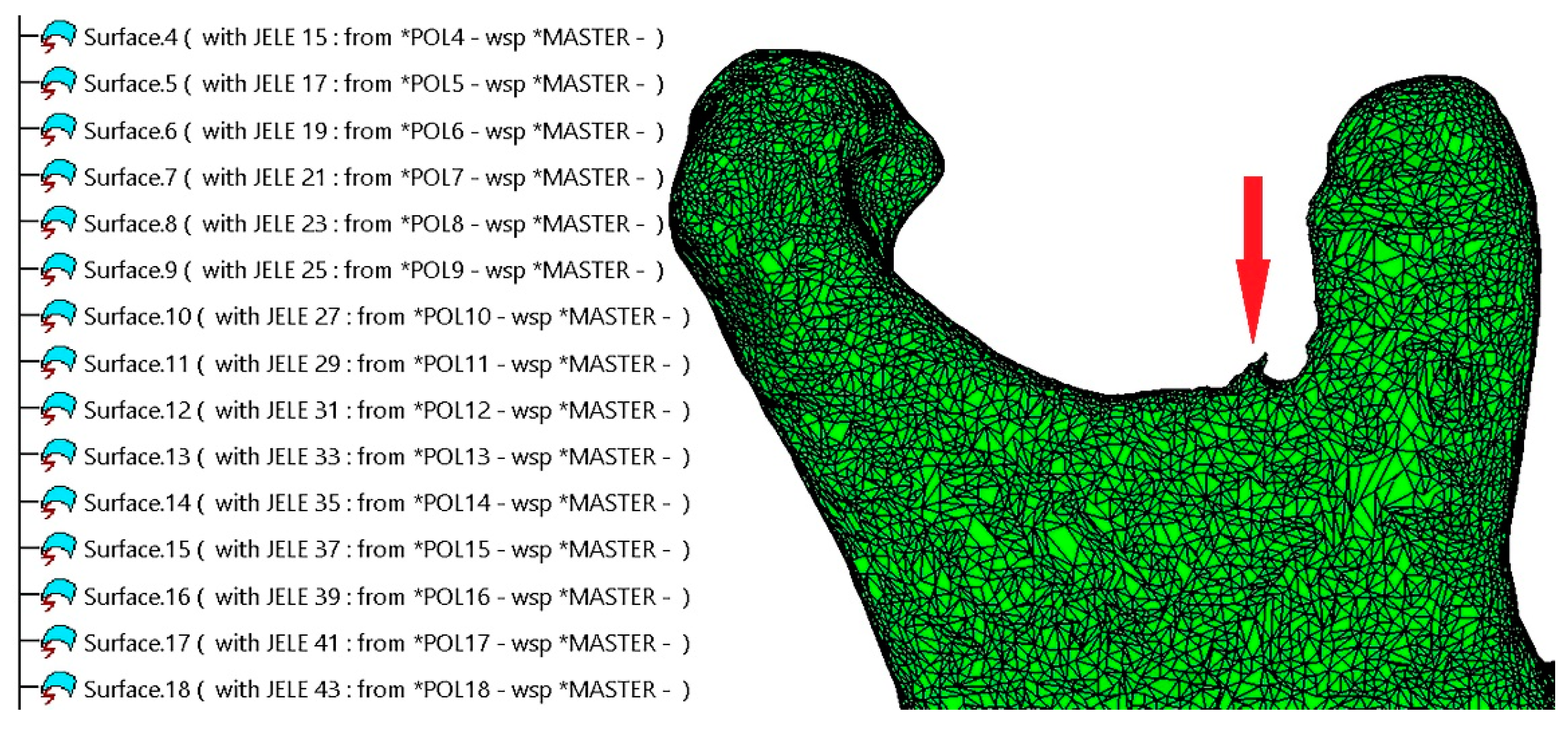
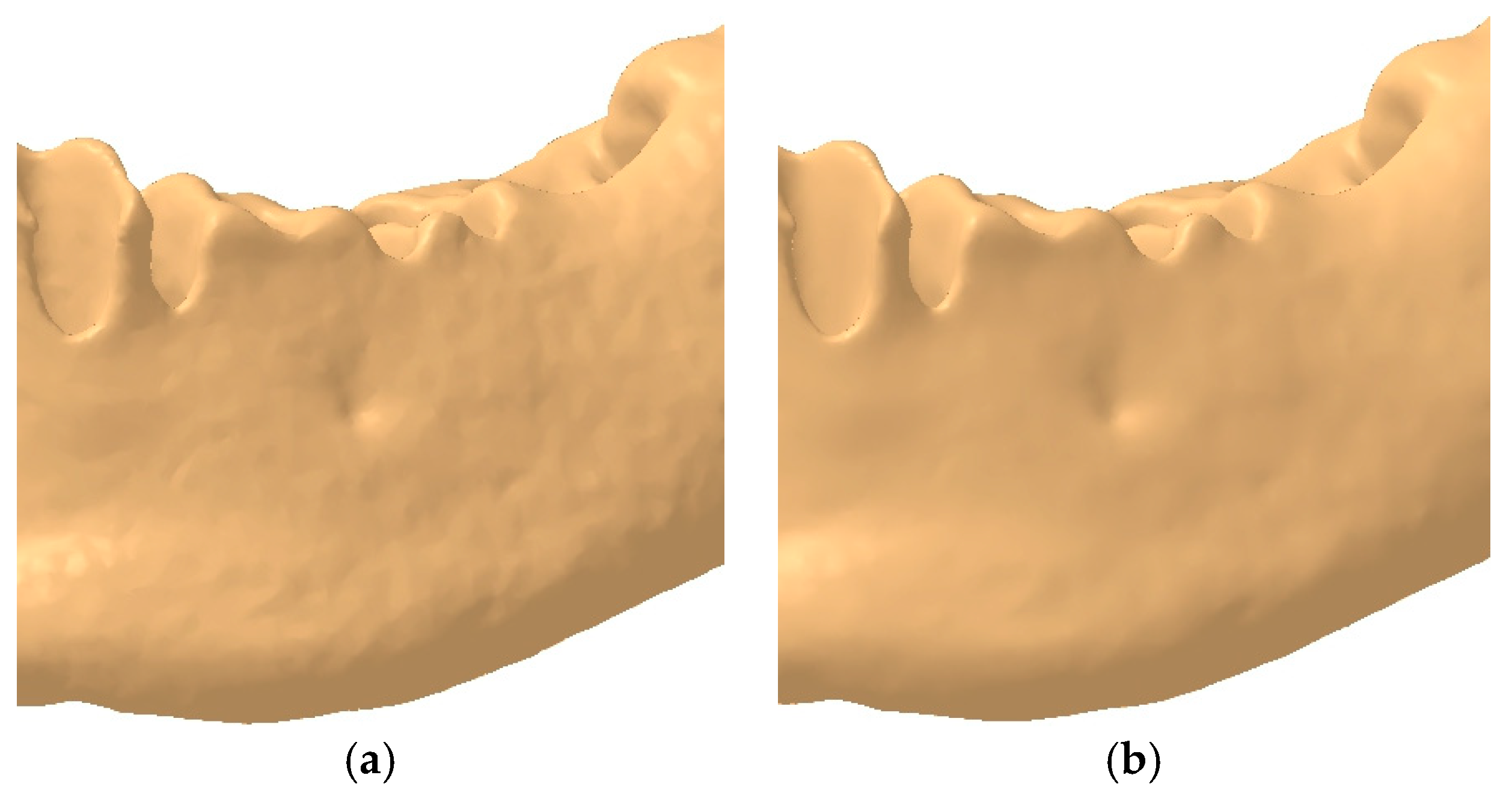
2.1. Refinement of the Mandibular Testing Model
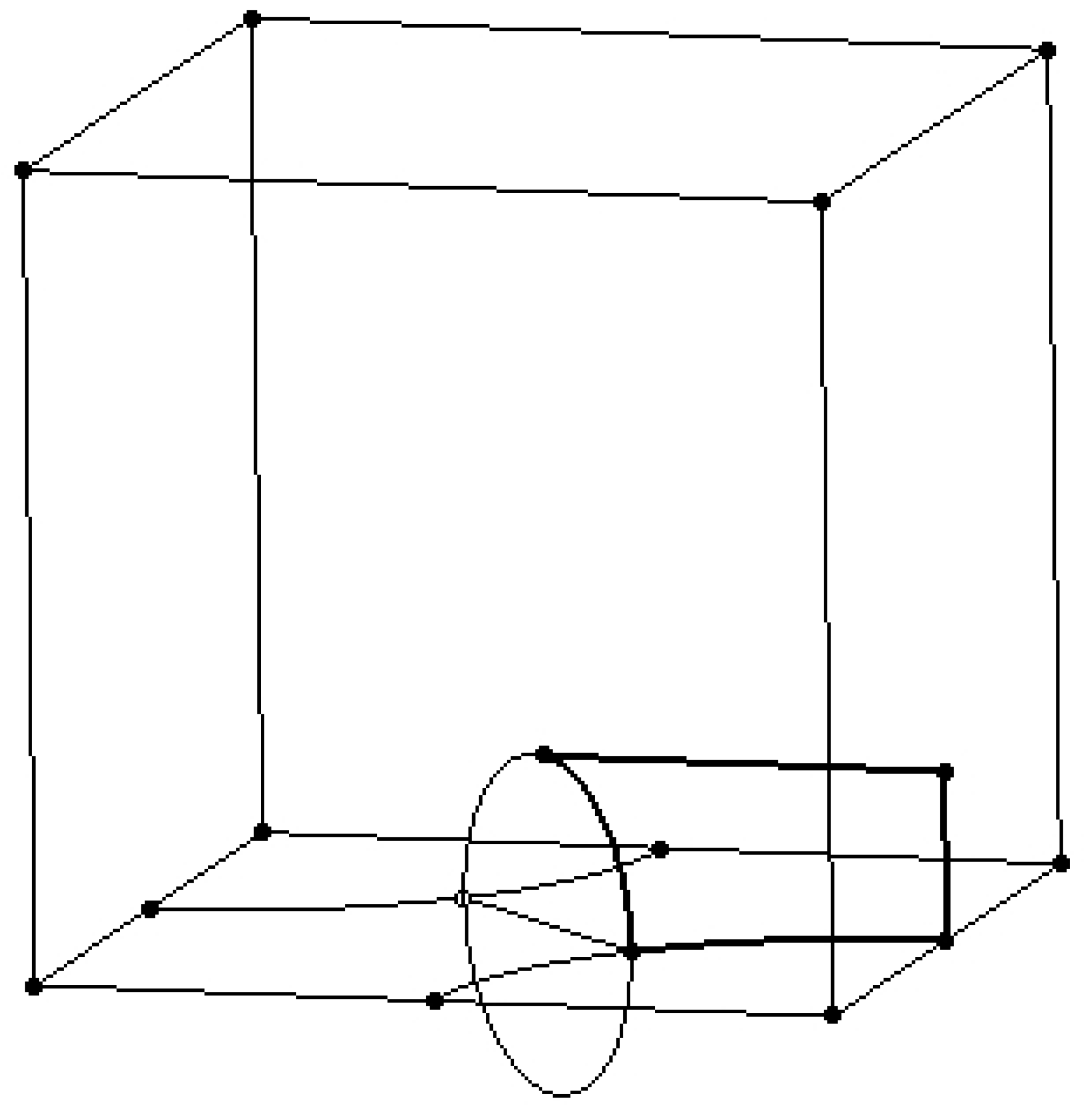
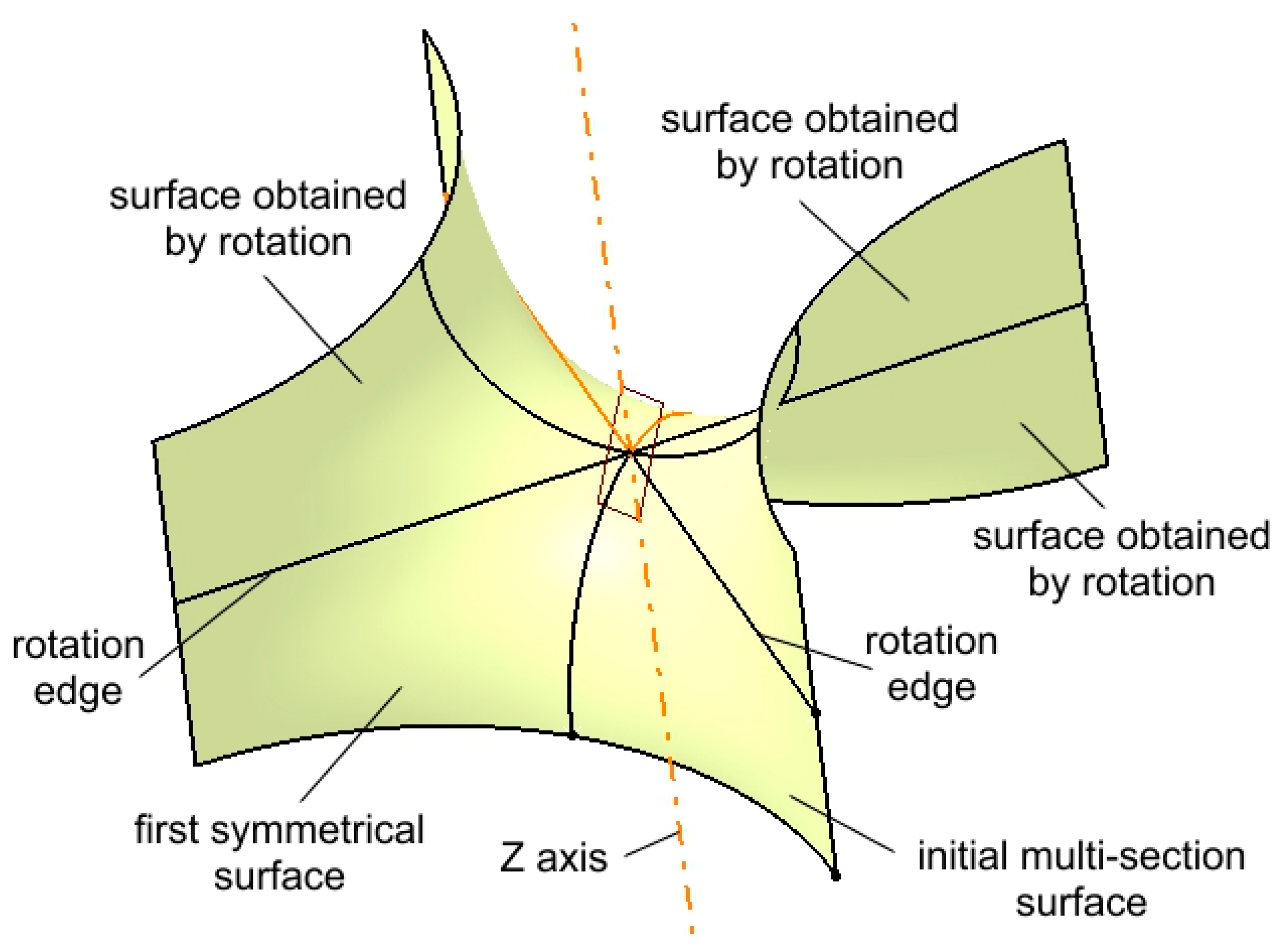
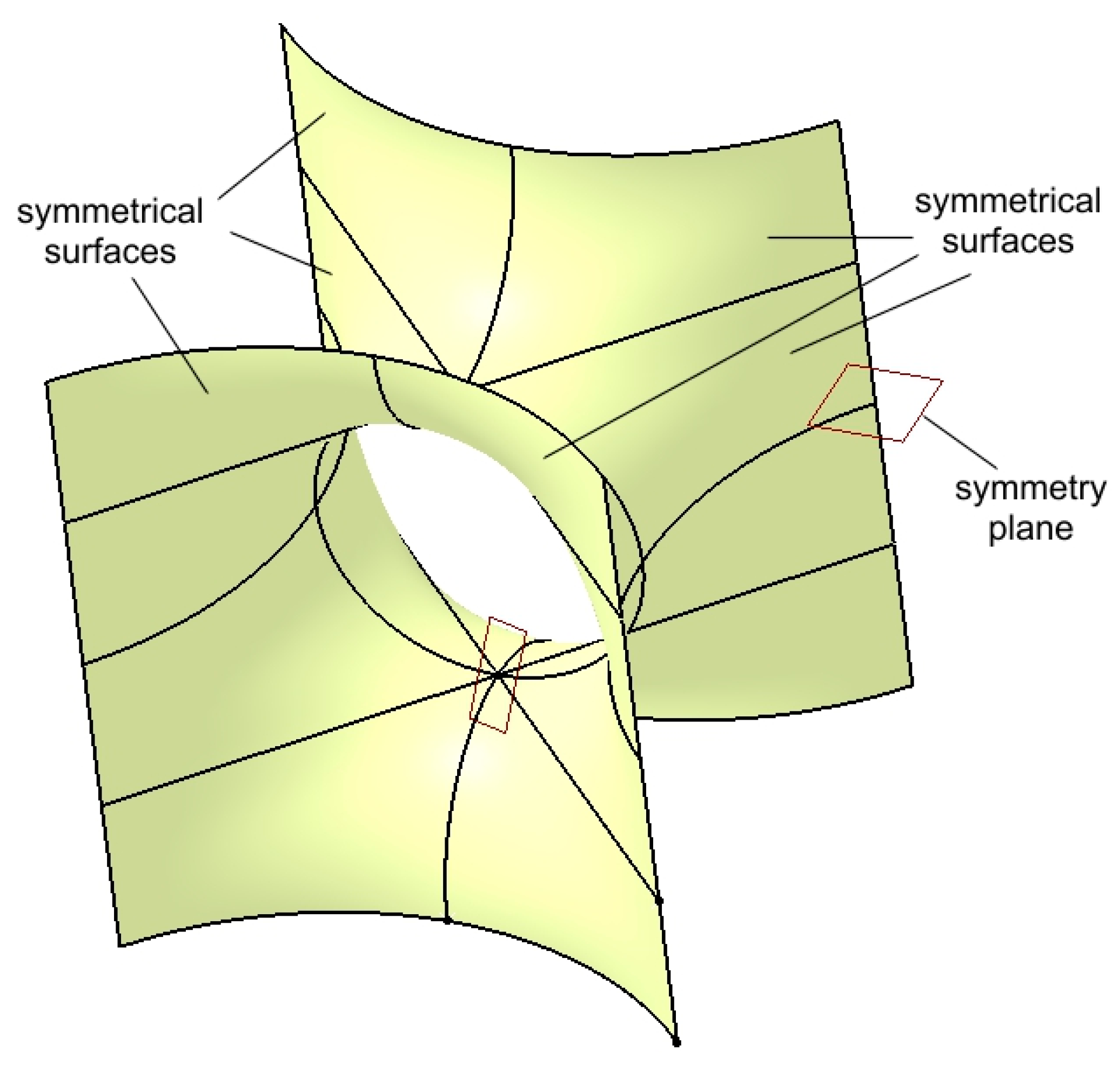
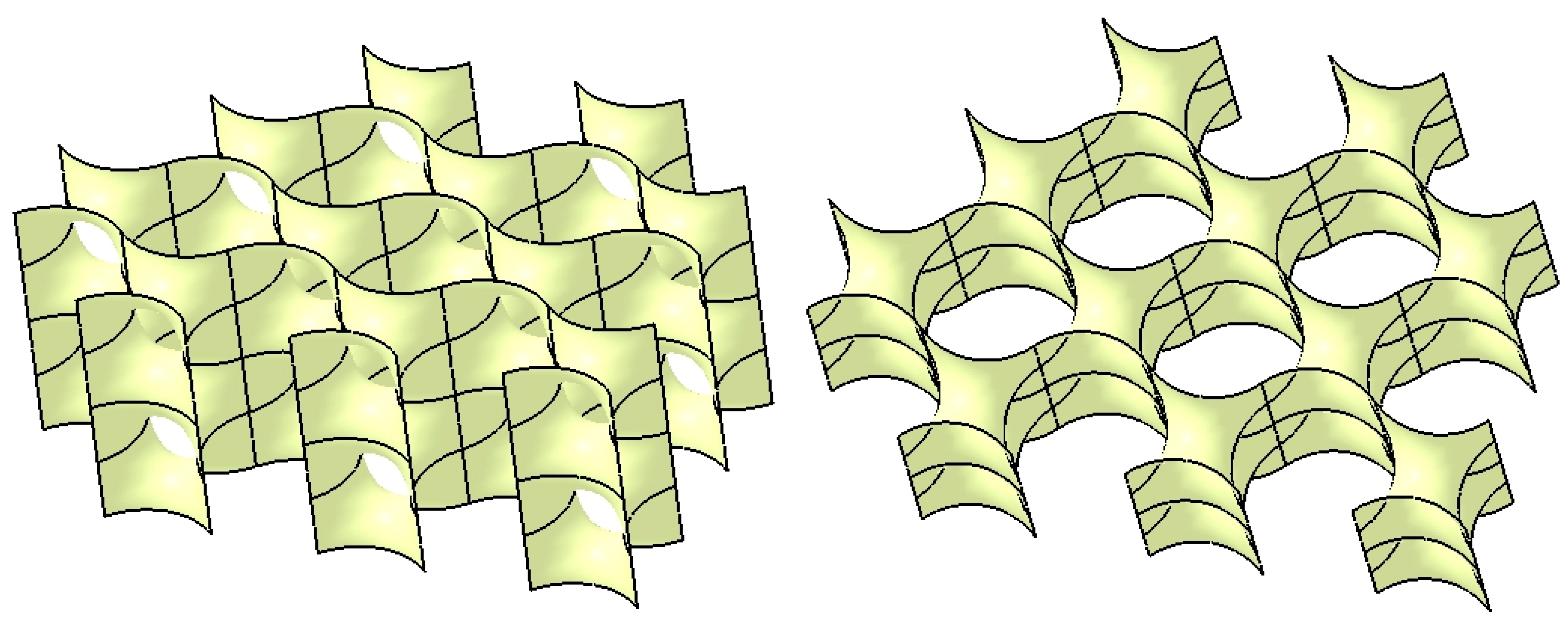
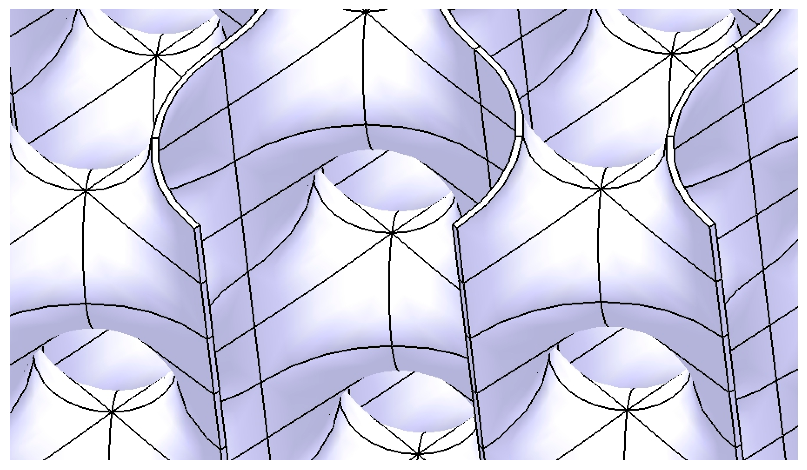
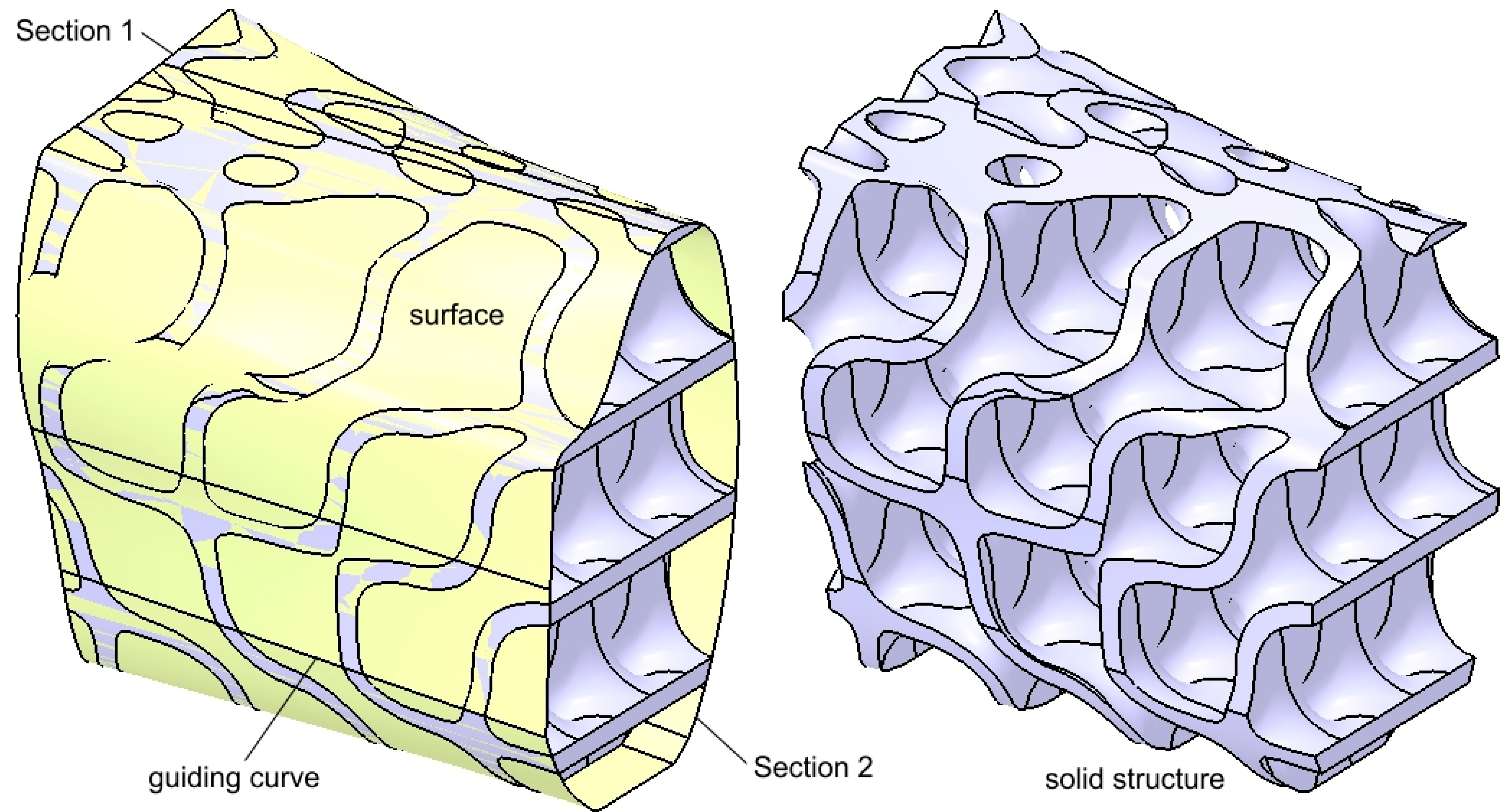
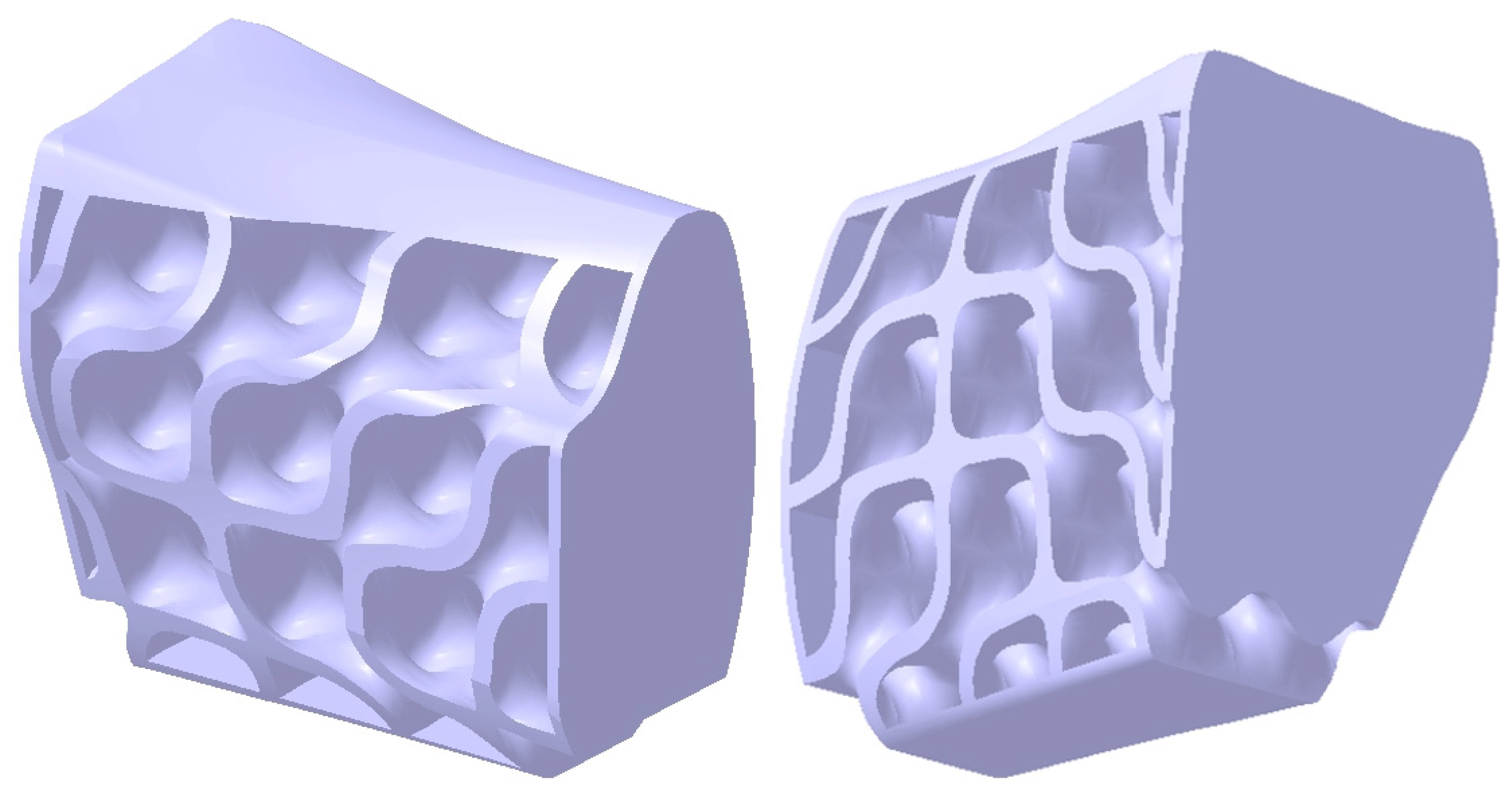
2.2. Design of the Hollow Structure
- -
- A vertical line is positioned on the right-side face of the cube;
- -
- A horizontal line connects the end of the vertical line to the upper quadrant point of the circle.
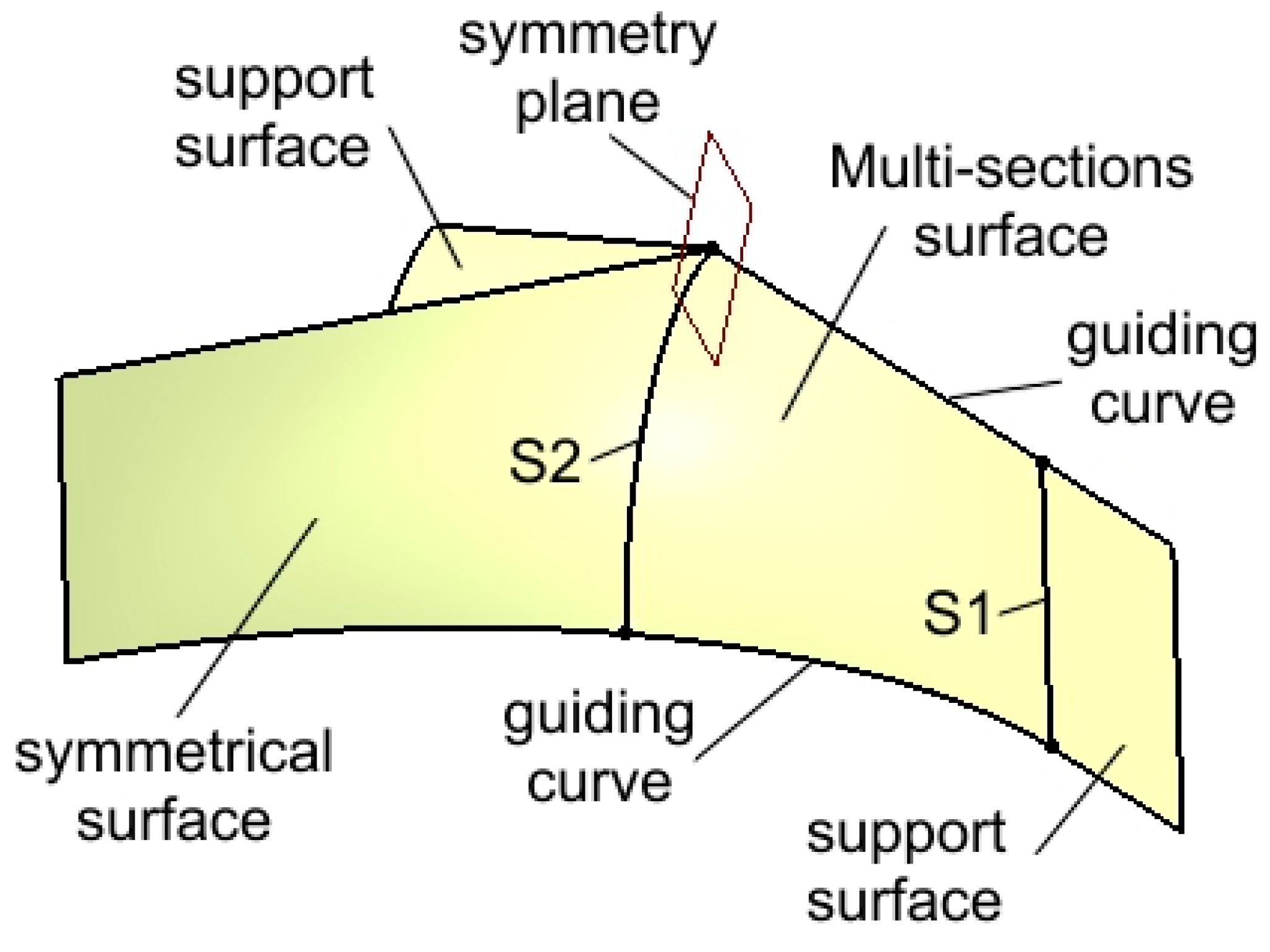
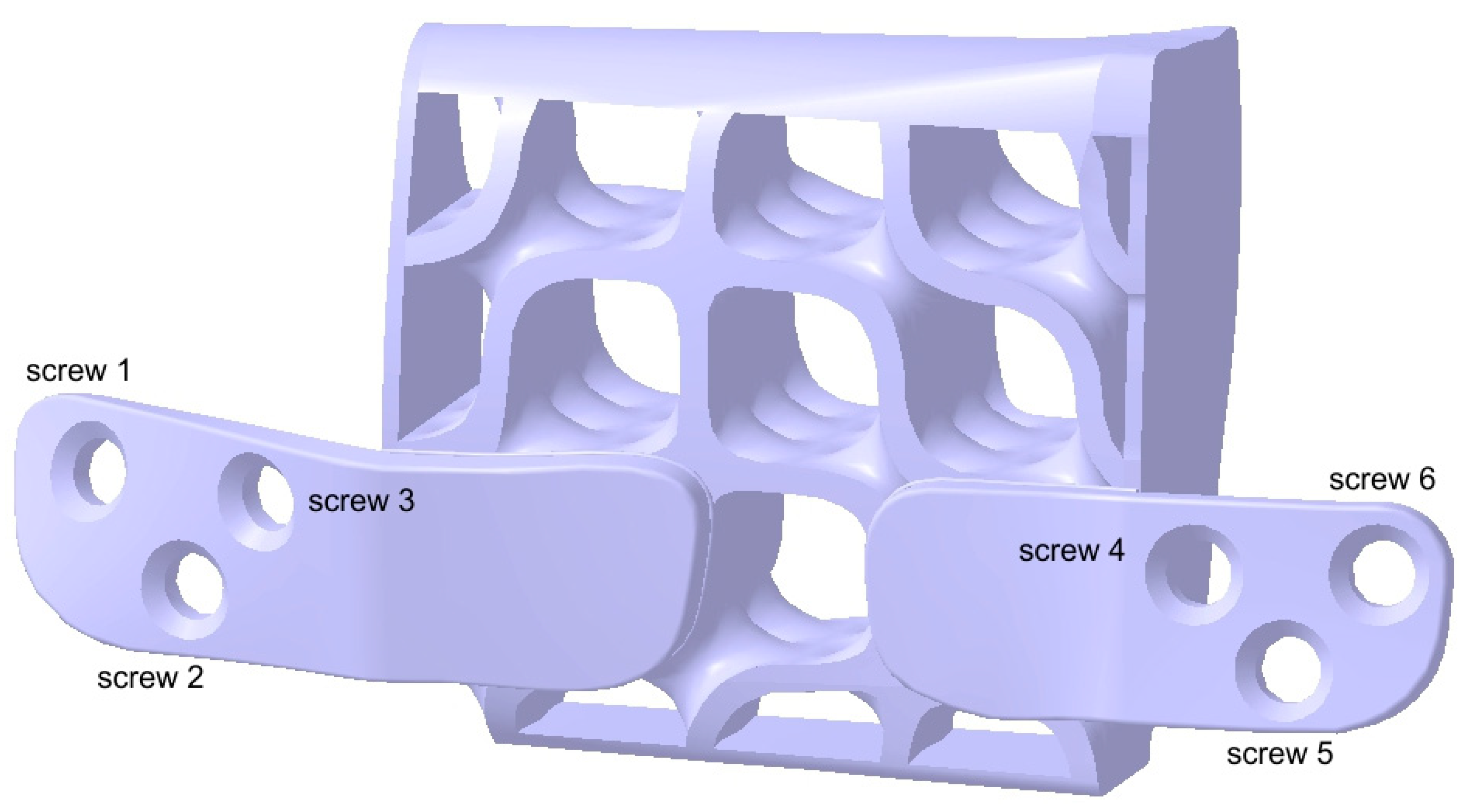
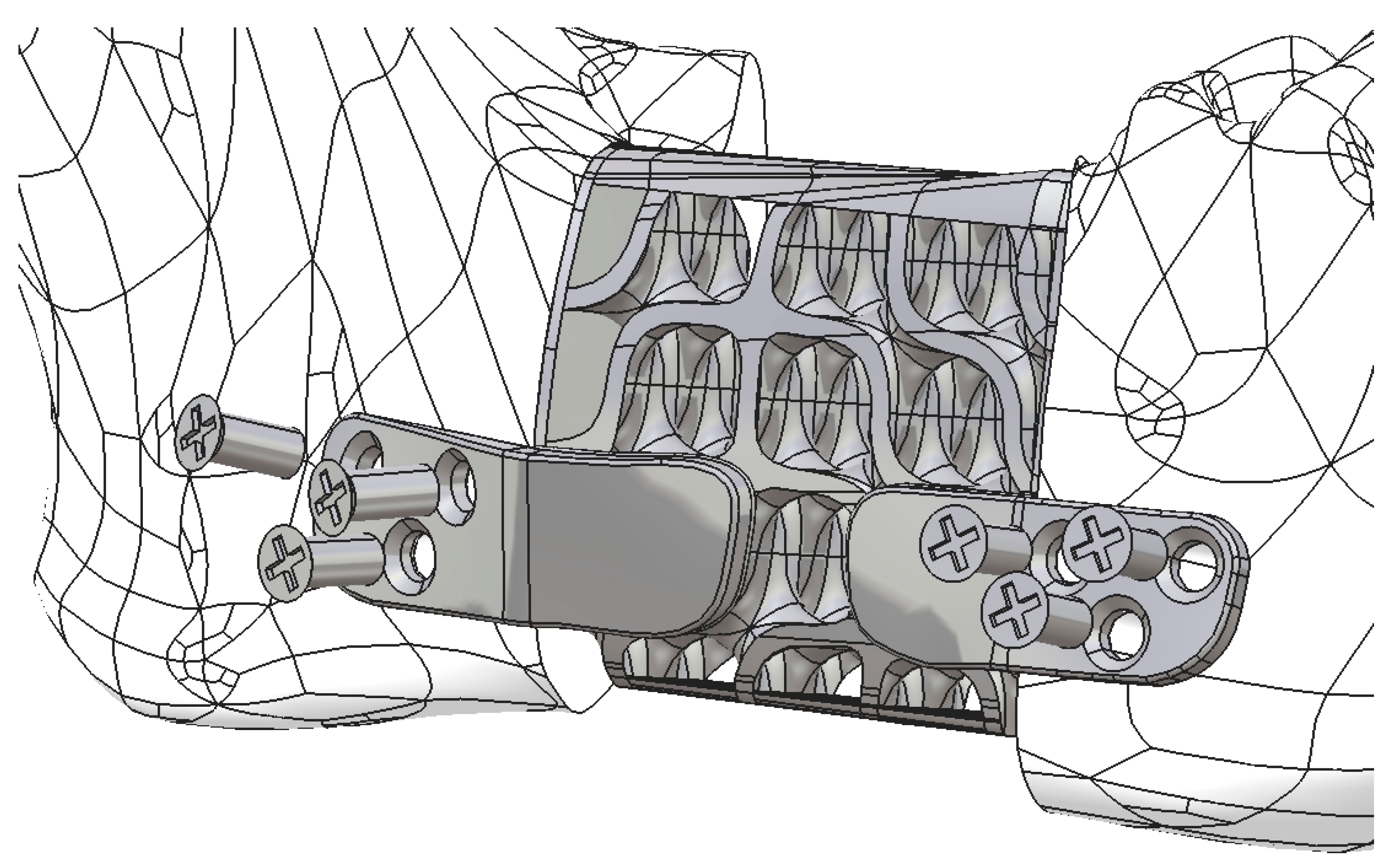
2.3. Design of the Mandibular Reconstruction Part
2.4. FEA Simulation: Titanium Versus PEEK
3. Results
4. Discussion
4.1. Comparative Analysis of Titanium and PEEK Reconstructions
4.2. Clinical Implications and Future Directions
4.3. Limits of the Present Study
5. Conclusions
Supplementary Materials
Author Contributions
Funding
Data Availability Statement
Conflicts of Interest
Abbreviations
| STL | Standard Tessellation Language |
| CASP | computer-assisted surgical planning |
| PSI | patient-specific implant |
| FEA | Finite Element Analysis |
| CBCT | Cone Beam Computed Tomography |
| DICOM | Digital Imaging and Communications in Medicine |
| TPMS | Triply Periodic Minimal Surface |
| PEEK | Polyetheretherketone |
| CAD/CAM | Computer-Aided Design/Computer-Aided Manufacturing |
References
- Aftabi, H.; Zaraska, K.; Eghbal, A.; McGregor, S.; Prisman, E.; Hodgson, A.; Fels, S. Computational models and their applications in biomechanical analysis of mandibular reconstruction surgery. Comput. Biol. Med. 2024, 169, 107887. [Google Scholar] [CrossRef]
- Gasparro, R.; Giordano, F.; Campana, M.D.; Aliberti, A.; Landolfo, E.; Dolce, P.; Sammartino, G.; di Lauro, A.E. The Effect of Conservative vs. Radical Treatment of Ameloblastoma on Recurrence Rate and Quality of Life: An Umbrella Review. J. Clin. Med. 2024, 13, 5339. [Google Scholar] [CrossRef]
- Brown, J.S.; Barry, C.; Ho, M.; Shaw, R. A new classification for mandibular defects after oncological resection. Lancet Oncol. 2016, 17, e23–e30. [Google Scholar] [CrossRef] [PubMed]
- Gupta, L.; Mishra, A.; Gurav, S.V.; Dholam, K.; Pal, A.; Kumar, A. Factors associated with mandibular deviation and proposed classification and treatment guidelines for applying mandibular guidance: A retrospective analysis of 185 patients with segmental mandibulectomy. J. Prosthet. Dent. 2024, in press. [Google Scholar] [CrossRef] [PubMed]
- Moubayed, S.P.; L’Heureux-Lebeau, B.; Christopoulos, A.; Sampalis, J.S.; Letourneau-Guillon, L.; Bissada, E.; Guertin, L.; Harris, P.G.; Danino, A.M.; Ayad, T. Osteocutaneous free flaps for mandibular reconstruction: Systematic review of their frequency of use and a preliminary quality of life comparison. J. Laryngol. Otol. 2014, 128, 1034–1043. [Google Scholar] [CrossRef]
- Bengur, F.B.; Humar, P.; Saadoun, R.; Khan, N.; Anstadt, E.; Dang, S.; Fadia, N.; Moroni, E.A.; Bottegal, M.T.; Acarturk, T.O.; et al. Computer-Aided Design and Manufacturing in Free Fibula Reconstruction of the Mandible: Comparison of Long-Term Outcomes with the Conventional Technique. Plast. Reconstr. Surg 2024. Online ahead of print. [Google Scholar] [CrossRef]
- Kumar, B.P.; Venkatesh, V.; Kumar, K.A.J.; Yadav, B.Y.; Mohan, S.R. Mandibular Reconstruction: Overview. J. Maxillofac. Oral Surg. 2015, 15, 425–441. [Google Scholar] [CrossRef] [PubMed]
- Ma, H.; Van Dessel, J.; Shujaat, S.; Bila, M.; Sun, Y.; Politis, C.; Jacobs, R. Long-term survival of implant-based oral rehabilitation following maxillofacial reconstruction with vascularized bone flap. Int. J. Implant Dent. 2022, 8, 15. [Google Scholar] [CrossRef]
- Ureel, M.; Boderé, P.J.; Denoiseux, B.; Corthouts, P.; Coopman, R. Mandibular Reconstruction with Osseous Free Flap and Immediate Prosthetic Rehabilitation (Jaw-in-a-Day): In-House Manufactured Innovative Modular Stackable Guide System. Bioengineering 2024, 11, 1254. [Google Scholar] [CrossRef]
- Weyh, A.M.; Fernandes, R.P. Narrative review: Fibula free flap, indications, tips, and pitfalls. Front. Oral Maxillofac. Med. 2021, 3, 1–7. [Google Scholar] [CrossRef]
- Yalamanchi, P.; Peddireddy, N.S.; McMichael, B.; Keilin, C.; Casper, K.A.; Malloy, K.M.; Moyer, J.S.; Prince, M.E.P.; Rosko, A.J.; Stucken, C.L.; et al. Team-Based Surgical Approach to Head and Neck Microvascular Free Flap Reconstruction. JAMA Otolaryngol. Head Neck Surg. 2023, 149, 1021–1026. [Google Scholar] [CrossRef]
- Martola, M.; Lindqvist, C.; Hänninen, H.; Al-Sukhun, J. Fracture of titanium plates used for mandibular reconstruction following ablative tumor surgery. J. Biomed. Mater. Res. Part B Appl. Biomater. 2007, 80B, 345–352. [Google Scholar] [CrossRef]
- Padilla, P.L.; Mericli, A.F.; Largo, R.D.; Garvey, P.B. Computer-Aided Design and Manufacturing versus Conventional Surgical Planning for Head and Neck Reconstruction: A Systematic Review and Meta-Analysis. Plast. Reconstr. Surg. 2021, 148, 183–192. [Google Scholar] [CrossRef] [PubMed]
- Sharma, N.; Aghlmandi, S.; Dalcanale, F.; Seiler, D.; Zeilhofer, H.F.; Honigmann, P.; Thieringer, F.M. Quantitative assessment of point-of-care 3D-printed patient-specific polyetheretherketone (PEEK) cranial implants. Int. J. Mol. Sci. 2021, 22, 8521. [Google Scholar] [CrossRef]
- Tuikampee, S.; Chaijareenont, P.; Rungsiyakull, P.; Yavirach, A. Titanium Surface Modification Techniques to Enhance Osteoblasts and Bone Formation for Dental Implants: A Narrative Review on Current Advances. Metals 2024, 14, 515. [Google Scholar] [CrossRef]
- Cristache, C.-M.; Burlibasa, M.; Tanase, G.; Nitescu, M.; Neamtu, R.; Ciochinaru, A. Titanium as dental implant material. Metal. Int. 2009, XIV, 14–16. [Google Scholar]
- Bandyopadhyay, A.; Mitra, I.; Goodman, S.B.; Kumar, M.; Bose, S. Improving biocompatibility for next generation of metallic implants. Prog. Mater. Sci. 2023, 133, 101053. [Google Scholar] [CrossRef]
- Hijazi, K.M.; Dixon, S.J.; Armstrong, J.E.; Rizkalla, A.S. Titanium Alloy Implants with Lattice Structures for Mandibular Reconstruction. Materials 2023, 17, 140. [Google Scholar] [CrossRef]
- Li, J.; Fan, H.; Li, H.; Hua, L.; Du, J.; He, Y.; Jin, Y. Recent Advancements in the Surface Modification of Additively Manufactured Metallic Bone Implants. Addit. Manuf. Front. 2025, 4, 200195. [Google Scholar] [CrossRef]
- Huber, F.A.; Sprengel, K.; Müller, L.; Graf, L.C.; Osterhoff, G.; Guggenberger, R. Comparison of different CT metal artifact reduction strategies for standard titanium and carbon-fiber reinforced polymer implants in sheep cadavers. BMC Med. Imaging 2021, 21, 29. [Google Scholar] [CrossRef]
- Lommen, J.; Schorn, L.; Sproll, C.; Kübler, N.R.; Nicolini, L.F.; Merfort, R.; Dilimulati, A.; Hildebrand, F.; Rana, M.; Greven, J. Mechanical Fatigue Performance of Patient-Specific Polymer Plates in Oncologic Mandible Reconstruction. J. Clin. Med. 2022, 11, 3308. [Google Scholar] [CrossRef] [PubMed]
- Midthun, P.; Kirkhus, E.; Østerås, B.H.; Høiness, P.R.; England, A.; Johansen, S. Metal artifact reduction on musculoskeletal CT: A phantom and clinical study. Eur. Radiol. Exp. 2023, 7, 46. [Google Scholar] [CrossRef]
- Ghionea, I.G.; Tarba, C.I.; Cristache, C.M.; Filipov, I.; Beuran, I.A. A Comparative Finite Element Analysis of Titanium, Autogenous Bone, and Polyetheretherketone (PEEK)-Based Solutions for Mandibular Reconstruction. Materials 2025, 18, 314. [Google Scholar] [CrossRef]
- Zhong, S.; Shi, Q.; Van Dessel, J.; Gu, Y.; Sun, Y.; Yang, S. Biomechanical validation of structural optimized patient-specific mandibular reconstruction plate orienting additive manufacturing. Comput. Methods Programs Biomed. 2022, 224, 107023. [Google Scholar] [CrossRef]
- Li, C.H.; Wu, C.H.; Lin, C.L. Design of a patient-specific mandible reconstruction implant with dental prosthesis for metal 3D printing using integrated weighted topology optimization and finite element analysis. J. Mech. Behav. Biomed. Mater. 2020, 105, 103700. [Google Scholar] [CrossRef]
- Zhong, S.; Shi, Q.; Sun, Y.; Yang, S.; Van Dessel, J.; Gu, Y.; Chen, X.; Lübbers, H.T.; Politis, C. Biomechanical comparison of locking and non-locking patient-specific mandibular reconstruction plate using finite element analysis. J. Mech. Behav. Biomed. Mater. 2021, 124, 104849. [Google Scholar] [CrossRef]
- Harrysson, O.L.A.; Hosni, Y.A.; Nayfeh, J.F. Custom-designed orthopedic implants evaluated using finite element analysis of patient-specific computed tomography data: Femoral-component case study. BMC Musculoskelet. Disord. 2007, 8, 91. [Google Scholar] [CrossRef]
- Ayhan, M.; Cankaya, A.B. Custom-made Subperiosteal Implants: A Finite Element Analysis on Monoblock and Dual Implant Systems in Atrophic Maxilla. Int. J. Med. Sci. 2023, 20, 1755. [Google Scholar] [CrossRef]
- Díaz, J.; González-Estrada, O.A.; López, C. Biomechanical analysis of a cranial Patient Specific Implant on the interface with the bone using the Finite Element Method. IFMBE Proc. 2017, 60, 405–408. [Google Scholar] [CrossRef]
- Longhitano, G.A.; Chiarelli, M.; Prada, D.; De Carvalho Zavaglia, C.A.; Maciel Filho, R. Personalized lattice-structured prosthesis as a graftless solution for mandible reconstruction and prosthetic restoration: A finite element analysis. J. Mech. Behav. Biomed. Mater. 2024, 152, 106460. [Google Scholar] [CrossRef]
- Fedorov, A.; Beichel, R.; Kalpathy-Cramer, J.; Finet, J.; Fillion-Robin, J.-C.; Pujol, S.; Bauer, C.; Jennings, D.; Fennessy, F.; Sonka, M. 3D Slicer as an image computing platform for the Quantitative Imaging Network. Magn. Reson. Imaging 2012, 30, 1323–1341. [Google Scholar] [PubMed]
- Zhang, Y.; Zhang, J.; Zhao, X.; Li, Y.; Che, S.; Yang, W.; Han, L. Mechanical behaviors regulation of triply periodic minimal surface structures with crystal twinning. Addit. Manuf. 2022, 58, 103036. [Google Scholar] [CrossRef]
- Triply Periodic Minimal Surfaces. Available online: http://kenbrakke.com/evolver/examples/periodic/periodic.html (accessed on 10 February 2025).
- Surfaces. Available online: https://mathcurve.com/surfaces.gb/surfaces.shtml (accessed on 10 February 2025).
- Deng, Y.; Mieczkowski, M. Three-dimensional periodic cubic membrane structure in the mitochondria of amoebae Chaos carolinensis. Protoplasma 1998, 203, 16–25. [Google Scholar] [CrossRef]
- Jiang, S.; Göpfert, A.; Abetz, V. Novel Morphologies of Block Copolymer Blends via Hydrogen Bonding. Macromolecules 2003, 36, 6171–6177. [Google Scholar] [CrossRef]
- Gandy, P.J.F.; Klinowski, J. The equipotential surfaces of cubic lattices. Chem. Phys. Lett. 2002, 360, 543–551. [Google Scholar] [CrossRef]
- Arsentev, M.; Topalov, E.; Balabanov, S.; Sysoev, E.; Shulga, I.; Akhmatnabiev, M.; Sychov, M.; Skorb, E.; Nosonovsky, M. Crystal-Inspired Cellular Metamaterials and Triply Periodic Minimal Surfaces. Biomimetics 2024, 9, 285. [Google Scholar] [CrossRef]
- WeWantToLearn.net. Scherk’s Minimal Surface. Available online: https://wewanttolearn.wordpress.com/2015/11/11/scherks-minimal-surface/ (accessed on 10 February 2025).
- Meeks, W.I.; Wolf, M. Minimal surfaces with the area growth of two planes: The case of infinite symmetry. J. Am. Math. Soc. 2007, 20, 441–465. [Google Scholar] [CrossRef]
- Archinect. Student Works: DRX 2012—Minimal Surface Highrise Structures, Features. Available online: https://archinect.com/features/article/60584804/student-works-drx-2012-minimal-surface-highrise-structures (accessed on 15 February 2025).
- Chibinyani, M.I.; Dzogbewu, T.C.; Maringa, M.; Muiruri, A. Lattice Structures Built with Different Polygon Hollow Shapes: A Review on Their Analytical Modelling and Engineering Applications. Appl. Sci. 2024, 14, 1582. [Google Scholar] [CrossRef]
- Warade, P.D.; Kshirsagar, R.; Mishra, P.; Prasad, P.; Sardeshmukh, A. Biomechanical evaluation of different fixation techniques following modified sagittal split ramus osteotomy using buccal step: An in vitro study. Natl. J. Maxillofac. Surg. 2022, 13, 443. [Google Scholar] [CrossRef]
- Shi, X.; Pan, T.; Wu, D.; Cai, N.; Chen, R.; Li, B.; Zhang, R.; Zhou, C.; Pan, J. Effect of different orientations of screw fixation for radial head fractures: A biomechanical comparison. J. Orthop. Surg. Res. 2017, 12, 143. [Google Scholar] [CrossRef]
- Kuan, F.C.; Hsu, K.L.; Lin, C.L.; Hong, C.K.; Yeh, M.L.; Su, W.R. Biomechanical properties of off-axis screw in Pauwels III femoral neck fracture fixation: Bicortical screw construct is superior to unicortical screw construct. Injury 2019, 50, 1889–1894. [Google Scholar] [CrossRef] [PubMed]
- Xue, R.; Lai, Q.; Xing, H.; Zhong, C.; Zhao, Y.; Zhu, K.; Deng, Y.; Liu, C. Finite element analysis and clinical application of 3D-printed Ti alloy implant for the reconstruction of mandibular defects. BMC Oral Health 2024, 24, 95. [Google Scholar] [CrossRef] [PubMed]
- Shen, Y.W.; Tsai, Y.S.; Hsu, J.T.; Shie, M.Y.; Huang, H.L.; Fuh, L.J. Biomechanical Analyses of Porous Designs of 3D-Printed Titanium Implant for Mandibular Segmental Osteotomy Defects. Materials 2022, 15, 576. [Google Scholar] [CrossRef]
- Mehle, K.; Eckert, A.W.; Gentzsch, D.; Schwan, S.; Ludtka, C.M.; Knoll, W.D. Evaluation of a New PEEK Mandibular Reconstruction Plate Design for Continuity Defect Therapy by Finite Element Analysis. Int. J. New Technol. Res. 2016, 2, 263461. [Google Scholar]
- Tanaka, E. Biomechanical and tribological properties of the temporomandibular joint. Front. Oral Maxillofac. Med. 2021, 3, 15. [Google Scholar] [CrossRef]
- Pinheiro, M.; Willaert, R.; Khan, A.; Krairi, A.; Van Paepegem, W. Biomechanical evaluation of the human mandible after temporomandibular joint replacement under different biting conditions. Sci. Rep. 2021, 11, 14034. [Google Scholar] [CrossRef] [PubMed]
- Ghionea, I.G. CATIA V5 Practical Studies Using Finite Element Analysis; CRC PRESS: Boca Raton, FL, USA, 2024; ISBN 9781032711645. [Google Scholar]
- Ghionea, I.G.; Vatamanu, O.E.B.; Cristescu, A.M.; David, M.; Stancu, I.C.; Butnarasu, C.; Cristache, C.M. A Finite Element Analysis of a Tooth-Supported 3D-Printed Surgical Guide without Metallic Sleeves for Dental Implant Insertion. Appl. Sci. 2023, 13, 9975. [Google Scholar] [CrossRef]
- Hossain, N.; Islam, M.A.; Shakib Ahmed, M.M.; Chowdhury, M.A.; Mobarak, M.H.; Rahman, M.M.; Helal Hossain, M.D. Advances and significances of titaniumin dental implant applications. Results Chem. 2024, 7, 101394. [Google Scholar] [CrossRef]
- Hong, J.Y.; Ko, S.Y.; Lee, W.; Chang, Y.Y.; Kim, S.H.; Yun, J.H. Enhancement of Bone Ingrowth into a Porous Titanium Structure to Improve Osseointegration of Dental Implants: A Pilot Study in the Canine Model. Materials 2020, 13, 3061. [Google Scholar] [CrossRef]
- Colnot, C.; Romero, D.M.; Huang, S.; Rahman, J.; Currey, J.A.; Nanci, A.; Brunski, J.B.; Helms, J.A. Molecular analysis of healing at a bone-implant interface. J. Dent. Res. 2007, 86, 862–867. [Google Scholar] [CrossRef]
- Albrektsson, T.; Johansson, C. Osteoinduction, osteoconduction and osseointegration. Eur. Spine J. 2001, 10, S96–S101. [Google Scholar] [CrossRef]
- Lekholm, U.; Zarb, G.A. Patient Selection and Preparation. Branemark, P.I., Zarb, G.A., Albrektsson, T., Eds.; Quintessence Publishing Co.: Chicago, IL, USA, 1985; ISBN 0-86715-129-3. [Google Scholar]
- Van Bael, S.; Chai, Y.C.; Truscello, S.; Moesen, M.; Kerckhofs, G.; Van Oosterwyck, H.; Kruth, J.P.; Schrooten, J. The effect of pore geometry on the in vitro biological behavior of human periosteum-derived cells seeded on selective laser-melted Ti6Al4V bone scaffolds. Acta Biomater. 2012, 8, 2824–2834. [Google Scholar] [CrossRef] [PubMed]
- Cristache, C.M.; Grosu, A.R.; Cristache, G.; Didilescu, A.C.; Totu, E.E. Additive Manufacturing and Synthetic Polymers for Bone Reconstruction in the Maxillofacial Region. Mater. Plast. 2018, 55, 555–562. [Google Scholar]
- Xue, W.; Krishna, B.V.; Bandyopadhyay, A.; Bose, S. Processing and biocompatibility evaluation of laser processed porous titanium. Acta Biomater. 2007, 3, 1007–1018. [Google Scholar] [CrossRef]
- Rumpler, M.; Woesz, A.; Dunlop, J.W.C.; Van Dongen, J.T.; Fratzl, P. The effect of geometry on three-dimensional tissue growth. J. R. Soc. Interface 2008, 5, 1173–1180. [Google Scholar] [CrossRef]
- Taniguchi, N.; Fujibayashi, S.; Takemoto, M.; Sasaki, K.; Otsuki, B.; Nakamura, T.; Matsushita, T.; Kokubo, T.; Matsuda, S. Effect of pore size on bone ingrowth into porous titanium implants fabricated by additive manufacturing: An in vivo experiment. Mater. Sci. Eng. C 2016, 59, 690–701. [Google Scholar] [CrossRef] [PubMed]
- Gao, X.; Fraulob, M.; Haïat, G. Biomechanical behaviours of the bone–implant interface: A review. J. R. Soc. Interface 2019, 16, 20190259. [Google Scholar] [CrossRef]
- Shala, K.; Tmava-Dragusha, A.; Dula, L.; Pustina-Krasniqi, T.; Bicaj, T.; Ahmedi, E.; Lila, Z. Evaluation of Maximum Bite Force in Patients with Complete Dentures. Open Access Maced. J. Med. Sci. 2018, 6, 559. [Google Scholar] [CrossRef]
- Wei, X.; Zhou, W.; Tang, Z.; Wu, H.; Liu, Y.; Dong, H.; Wang, N.; Huang, H.; Bao, S.; Shi, L.; et al. Magnesium surface-activated 3D printed porous PEEK scaffolds for in vivo osseointegration by promoting angiogenesis and osteogenesis. Bioact. Mater. 2022, 20, 16–28. [Google Scholar] [CrossRef]
- Cheng, K.J.; Shi, Z.Y.; Wang, R.; Jiang, X.F.; Xiao, F.; Liu, Y.F. 3D printed PEKK bone analogs with internal porosity and surface modification for mandibular reconstruction: An in vivo rabbit model study. Biomater. Adv. 2023, 151, 213455. [Google Scholar] [CrossRef]
- Parisi, L.; Ghezzi, B.; Bianchi, M.G.; Toffoli, A.; Rossi, F.; Bussolati, O.; Macaluso, G.M. Titanium dental implants hydrophilicity promotes preferential serum fibronectin over albumin competitive adsorption modulating early cell response. Mater. Sci. Eng. C. 2020, 117, 111307. [Google Scholar] [CrossRef]


| Component | Finite Element Size, mm | Absolute Sag, mm | Finite Element Type | Material |
|---|---|---|---|---|
| Mandible | 1.5 | 0.8 | Parabolic | Bone |
| Reconstruction part with fixing plates | 1.8 | 1 | Parabolic | Ti-Grade-4 (TI75A) or PEEK |
| TMJ disks | 1.2 | 0.3 | Parabolic | Cartilage |
| Screws | 0.5 | 0.2 | Linear | Ti-Grade-4 (TI75A) |
| Component | Von Mises Stress, MPa | Translational Displacement Vector, mm | Component | Von Mises Stress, MPa | Translational Displacement Vector, mm |
|---|---|---|---|---|---|
| Test 1. Forces: A: 30N, B: 12N, C: 40N, D: 30N | |||||
| Mandible | 20.5 | 0.942 | Reconstruction | 65 | 0.852 |
| TMJ 1 | 2.53 | 0.093 | Screw 4 | 2.85 × 10⁻⁸ | - |
| TMJ 2 | 2.13 | 0.072 | Screw 5 | 1.74 × 10⁻⁸ | - |
| Test 2. Forces: A: 45N, B: 20N, C: 50N, D: 45N | |||||
| Mandible | 26.5 | 0.911 | Reconstruction | 102 | 0.828 |
| TMJ 1 | 3.06 | 0.105 | Screw 4 | 4.55 × 10⁻⁸ | - |
| TMJ 2 | 2.28 | 0.08 | Screw 5 | 5.18 × 10⁻⁸ | - |
| Test 3. Forces: A: 55N, B: 30N, C: 60N, D: 55N | |||||
| Mandible | 37.3 | 1.51 | Reconstruction | 123 | 1.37 |
| TMJ 1 | 4.27 | 0.155 | Screw 4 | 1.15 × 10⁻⁷ | - |
| TMJ 2 | 3.51 | 0.12 | Screw 5 | 1.05 × 10⁻⁷ | - |
| Test 4. Forces: A: 65N, B: 35N, C: 65N, D: 60N | |||||
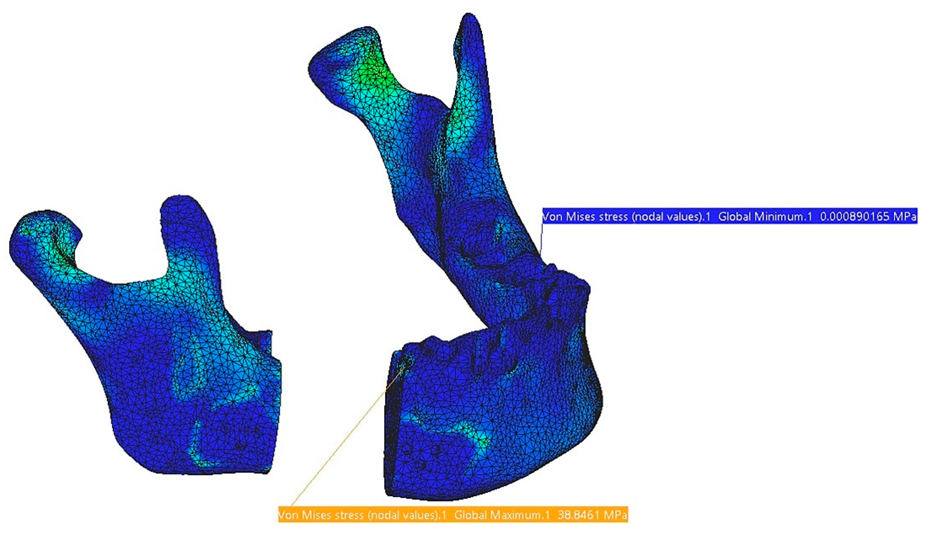
| Mandible | 38.8 | 1.11 | Reconstruction | 149 | 1.01 |
| TMJ 1 | 4.03 | 0.137 | Screw 4 | 9.12 × 10⁻⁸ | - |
| TMJ 2 | 2.91 | 0.103 | Screw 5 | 1.09 × 10⁻⁷ | - |
| Test 5. Forces: A: 75N, B: 50N, C: 70N, D: 65N | |||||
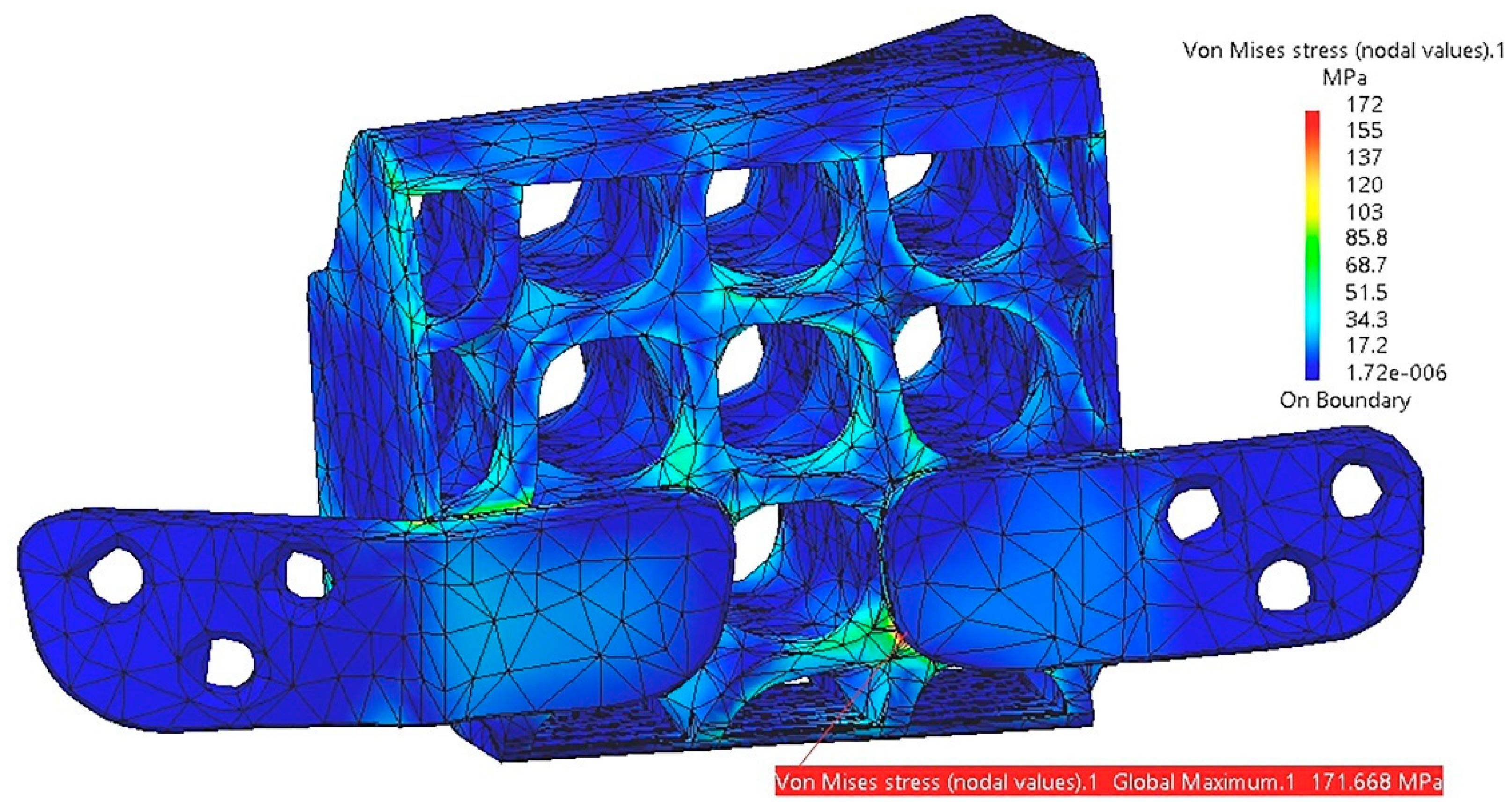
| Mandible | 49.5 | 1.56 | Reconstruction | 172 | 1.41 |
| TMJ 1 | 4.9 | 0.174 | Screw 4 | 9.12 × 10⁻⁸ | - |
| TMJ 2 | 3.86 | 0.133 | Screw 5 | 1.09 × 10⁻⁷ | - |
| Component | Von Mises Stress, MPa | Translational Displacement Vector, mm | Component | Von Mises Stress, MPa | Translational Displacement Vector, mm |
|---|---|---|---|---|---|
| Test 1. Forces: A: 30N, B: 12N, C: 40N, D: 30N | |||||
| Mandible | 12.9 | 0.915 | Reconstruction | 47.7 | 0.85 |
| TMJ 1 | 2.85 | 0.097 | Screw 4 | 1.11 × 10⁻⁷ | - |
| TMJ 2 | 1.98 | 0.069 | Screw 5 | 9.87 × 10⁻⁸ | - |
| Test 2. Forces: A: 45N, B: 20N, C: 50N, D: 45N | |||||
| Mandible | 15.4 | 0.867 | Reconstruction | 73.1 | 0.822 |
| TMJ 1 | 3.57 | 0.12 | Screw 4 | 5.73 × 10⁻⁸ | - |
| TMJ 2 | 2.07 | 0.075 | Screw 5 | 6.27 × 10⁻⁸ | - |
| Test 3. Forces: A: 55N, B: 30N, C: 60N, D: 55N | |||||
| Mandible | 21.3 | 1.46 | Reconstruction | 90.5 | 1.37 |
| TMJ 1 | 4.93 | 0.166 | Screw 4 | 1.24 × 10⁻⁷ | - |
| TMJ 2 | 3.24 | 0.113 | Screw 5 | 8.99 × 10⁻⁸ | - |
| Test 4. Forces: A: 65N, B: 35N, C: 65N, D: 60N | |||||
| Mandible | 19.3 | 1.04 | Reconstruction | 108 | 0.993 |
| TMJ 1 | 4.88 | 0.163 | Screw 4 | 7.92 × 10⁻⁸ | - |
| TMJ 2 | 2.59 | 0.095 | Screw 5 | 7.17 × 10⁻⁸ | - |
| Test 5. Forces: A: 75N, B: 50N, C: 70N, D: 65N | |||||
| Mandible | 22.8 | 1.47 | Reconstruction | 127 | 1.39 |
| TMJ 1 | 6.03 | 0.201 | Screw 4 | 4.41 × 10⁻⁸ | - |
| TMJ 2 | 3.47 | 0.123 | Screw 5 | 4.57 × 10⁻⁸ | - |
| Component | Material | Density, kg/m3 | Yield Strength, MPa | Volume, mm3 | Mass, g |
|---|---|---|---|---|---|
| Reconstruction part without screws | Ti-Grade-4 | 4500 | 550 | 2206.51 | 9.929 |
| Reconstruction part without screws | PEEK | 1300 | 100 | 2206.51 | 2.868 |
| Screw | Ti-Grade-4 | 4500 | 550 | 14.83 | 0.07 |
| Reconstruction part with six screws | Ti-Grade-4 | 4500 | 550 | 2295.49 | 10.33 |
| Reconstruction part with six screws | PEEK + Ti-Grade-4 | 1300 4500 | 100 550 | 2295.49 | 3.269 |
Disclaimer/Publisher’s Note: The statements, opinions and data contained in all publications are solely those of the individual author(s) and contributor(s) and not of MDPI and/or the editor(s). MDPI and/or the editor(s) disclaim responsibility for any injury to people or property resulting from any ideas, methods, instructions or products referred to in the content. |
© 2025 by the authors. Licensee MDPI, Basel, Switzerland. This article is an open access article distributed under the terms and conditions of the Creative Commons Attribution (CC BY) license (https://creativecommons.org/licenses/by/4.0/).
Share and Cite
Ghionea, I.G.; Tarba, C.I.; Cristache, M.A.; Cristache, C.M. Comparative Evaluation of Symmetrical Titanium and Polyetheretherketone (PEEK) Hollow Structures for Mandibular Reconstruction: Strength, Geometry, and Biomechanical Performance. Symmetry 2025, 17, 499. https://doi.org/10.3390/sym17040499
Ghionea IG, Tarba CI, Cristache MA, Cristache CM. Comparative Evaluation of Symmetrical Titanium and Polyetheretherketone (PEEK) Hollow Structures for Mandibular Reconstruction: Strength, Geometry, and Biomechanical Performance. Symmetry. 2025; 17(4):499. https://doi.org/10.3390/sym17040499
Chicago/Turabian StyleGhionea, Ionut Gabriel, Cristian Ioan Tarba, Mircea Alexandru Cristache, and Corina Marilena Cristache. 2025. "Comparative Evaluation of Symmetrical Titanium and Polyetheretherketone (PEEK) Hollow Structures for Mandibular Reconstruction: Strength, Geometry, and Biomechanical Performance" Symmetry 17, no. 4: 499. https://doi.org/10.3390/sym17040499
APA StyleGhionea, I. G., Tarba, C. I., Cristache, M. A., & Cristache, C. M. (2025). Comparative Evaluation of Symmetrical Titanium and Polyetheretherketone (PEEK) Hollow Structures for Mandibular Reconstruction: Strength, Geometry, and Biomechanical Performance. Symmetry, 17(4), 499. https://doi.org/10.3390/sym17040499