Article

H∞ Control for Symmetric Human–Robot Interaction in Initial Attitude Calibration of Space Docking Hardware-in-the-Loop Tests

1
State Key Laboratory of Robotics and Systems, Harbin Institute of Technology, Harbin 150001, China
2
Shenyang Institute of Automation, Chinese Academy of Sciences, Shenyang 110016, China
3
University of Chinese Academy of Sciences, Beijing 100049, China
4
Song Jiang Laboratory, Harbin Institute of Technology, Harbin 150001, China
5
Aerospace System Engineering Shanghai, Shanghai 201109, China
*
Authors to whom correspondence should be addressed.
Symmetry 2025, 17(11), 1922; https://doi.org/10.3390/sym17111922
Submission received: 17 September 2025 / Revised: 25 October 2025 / Accepted: 6 November 2025 / Published: 10 November 2025
(This article belongs to the Section Physics)

Abstract

Initial attitude calibration is a critical yet challenging phase in hardware-in-the-loop (HIL) testing for space docking, often hindered by cumbersome procedures, safety concerns, and reliance on external equipment. This paper introduces a human–robot collaborative calibration method based on H∞ robust control. The core objective is to achieve symmetric pose alignment between docking mechanisms by allowing the operator to manually guide the test device, thereby rapidly obtaining initial attitude calibration results. An interactive model incorporating a time delay is established. Using H∞ synthesis, a stabilizing controller is designed to accurately track low-frequency operator commands while strongly suppressing high-frequency disturbances. Notably, the H∞ framework reconstructs an ideal interactive symmetry in human–robot collaboration by compensating for delays and disturbances. The solution to the Riccati equation within a game-theoretic framework effectively achieves symmetric optimization that balances tracking accuracy with safety constraints. Experimental results demonstrate that the method successfully compensates for system delays, enabling symmetric pose alignment while maintaining smooth and continuous motion of the docking mechanism. It also faithfully translates the operator’s low-frequency traction intent into motion. By retaining contact forces/torques within safe thresholds, the method balances interaction safety with operational precision, ultimately providing a reliable solution for initial attitude calibration in space docking HIL tests.

1. Introduction

Hardware-in-the-Loop (HIL) testing technology, which integrates physical prototypes with numerical models, has proven indispensable for verification in fields such as aerospace and industrial control. It offers a high-precision and cost-effective approach for performance testing and control strategy validation of complex systems [1]. In the field of aerospace engineering, Wang et al. [2] developed a dual-satellite HIL testing experimental platform to address the technical challenges associated with inter-satellite laser interferometry in gravitational wave detection missions. By establishing a ground-based simulation environment, they successfully replicated in-orbit laser ranging and interferometric behaviors. Similarly, Du et al. [3] focused on issues related to close-range spacecraft rendezvous, using an HIL testing system to validate strategies for improving angular navigation accuracy. Their work provided essential experimental support for the advancement of autonomous spacecraft rendezvous technology. In the industrial sector, HIL testing also plays a vital role. For instance, in precision tasks such as rotor assembly and bolt tightening, researchers have implemented HIL testing systems to optimize balance and preload distribution during assembly, thereby significantly improving the accuracy and efficiency of complex manufacturing processes [4]. Collectively, these findings highlight the critical importance of HIL testing technology in the modeling and validation of complex systems.
Despite notable advancements in HIL testing technology across these domains, current research exhibits significant shortcomings in the critical step of initial attitude calibration. Such deficiencies impede the ability to meet the requirements of testing scenarios where convenience and efficiency are paramount, ultimately compromising the accuracy of subsequent dynamic simulations and even posing risks of equipment damage. In the context of missile system HIL testing, Hu et al. [5] developed an experimental setup consisting of a three-degree-of-freedom motion platform and a servo-loading mechanism, enabling real-time detection and localization of failures in control surfaces and lifting surfaces. While their work advanced fault diagnosis during dynamic tests, it paid insufficient attention to attitude calibration in the initial testing phase and overlooked potential issues stemming from coordinate system misalignment. Similarly, Zhang et al. [6] proposed a reinforcement learning-based HIL testing method to address balance optimization in fan rotor assembly. Yet, their approach also neglected the initial attitude calibration stage, potentially causing the phase angle adjustments of the blades to deviate from correct reference points. Furthermore, existing studies on initial attitude calibration have largely depended on external high-precision instruments—such as laser rangefinders, total stations, or dedicated calibration fixtures—to measure the attitude parameters of physical prototypes offline before importing them into numerical models [7]. Although these methods can achieve high accuracy, they involve complex equipment setups that increase system cost and debugging complexity, while also limiting adaptability to dynamic adjustment needs. Therefore, the development of a convenient and reliable method for initial attitude calibration holds considerable theoretical and practical significance for enhancing HIL testing experiments.
This study employs a HIL test bench specifically designed for space docking mechanisms as the experimental platform. During the establishment of the initial coordinate system for HIL testing, the operator manually adjusts the pose of one docking mechanism to align it with its counterpart. This adjustment involves pushing, pulling, or rotating the end-effector of the target docking mechanism until the docking interfaces of both mechanisms achieve proper alignment. The entire alignment process consistently emphasizes the attainment of “goal symmetry”—a spatial pose alignment condition where the coordinate systems of the two docking mechanisms achieve either complete coincidence or mirror symmetry. This state represents the core objective of the initial attitude calibration procedure.
A 6-axis collaborative robotic arm equipped with a six-degree-of-freedom (6-DOF) force/torque sensor at its end-effector plays a critical role in the pose alignment process. It performs two primary functions: first, it acquires and transmits in real time the three-dimensional forces (Fx, Fy, Fz) and torques (Tx, Ty, Tz) generated during human–robot interaction, thereby providing accurate force/torque feedback for subsequent motion adjustments; second, it dynamically regulates its movement speed and acceleration based on the real-time force/torque signals. For instance, when the interaction force exceeds a predefined threshold, the robotic arm automatically and smoothly reduces its velocity from a higher initial value to a lower level while strictly constraining acceleration within a specified range to prevent inertial impact damage to the docking mechanism.
This dual-function design—integrating real-time sensing with dynamic adjustment—effectively reconstructs an ideal state of “interactive symmetry.” It ensures that during operator-guided traction, including fine corrections for minor pose deviations, the robotic arm’s motion response maintains high coordination with the operator’s input. The resulting motion remains smooth and jerk-free while exhibiting negligible delay, achieving close matching in both force transmission and kinematic correspondence.
The control strategy supporting this process is built upon an admittance control framework compliant with physical human–robot interaction standards. This framework not only maintains contact forces and interaction torques between the active and passive ends within a safe range—preventing structural damage to the docking mechanism and ensuring operator safety—but also guarantees smooth and continuous attitude trajectory throughout the alignment process, avoiding jerks or abrupt changes. These features collectively form a closed-loop control system that further facilitates the coordinated realization of both goal symmetry and interactive symmetry: while goal symmetry focuses on achieving precise pose alignment, interactive symmetry aims to establish a highly coordinated collaborative state between human and machine.
The proposed approach must address three fundamental challenges:
First, inherent time delays in command transmission, sensor filtering, and actuator response cause dynamic response mismatches, introducing significant phase deviations and lag. These delays can induce oscillatory behavior during attitude adjustments, increasing the risk of unintended collisions and complicating the calibration process, all of which must be managed under strict safety constraints.
Second, during the human-guided process for initial attitude calibration, the system is subjected to complex multi-source disturbances. These include measurement noise, robotic arm drive delays, parameter perturbations in the physical prototype, and environmental interference. These coupled, model-unknown uncertainties lead to deviations in the end-effector’s pose tracking, adversely affecting calibration accuracy and compromising the system’s robust stability. Consequently, effectively suppressing these disturbances without a precise model is crucial for ensuring reliable calibration.
Third, the manual guidance process must satisfy two conflicting requirements simultaneously—and these two requirements essentially serve to maintain ideal interactive symmetry between humans and machines, i.e., a smooth, force-matched, and lag-free collaborative relationship between the operator and the robotic arm: On one hand, it must strictly control the forces and torques of human–machine interaction within safety thresholds to prevent personnel injury or equipment damage, as excessive or asymmetric force/torque deviations would break the force balance in interactive symmetry and lead to risky collisions; on the other hand, it must ensure the robotic arm precisely tracks the operator’s low-frequency intentions without lag to achieve rapid calibration, since any response delay would disrupt the action synchronization in interactive symmetry and cause misalignment between the operator’s guidance intent and the robotic arm’s motion. This highlights the core challenge of balancing safety and tracking accuracy in dynamic human–machine interactions—and essentially, this balance is the key to safeguarding the stability of interactive symmetry throughout the calibration process.
To address these challenges, this paper incorporates time delays into the dynamic model and leverages the robustness of H∞ control theory, conducting targeted research as follows:
  • Compensation for control delays and imbalance:
In various control system scenarios, control delays and system imbalances often lead to performance degradation and reduced stability; thus, the investigation of compensation strategies holds significant engineering importance. Existing scholars have proposed multiple delay compensation methods for different application scenarios: Ma et al. [8] developed a novel vibration-absorbing wheel structure with time-delay feedback control for traditional wheel configurations, analyzed both delay-independent and delay-dependent stabilities of the system, and optimized the time-delay feedback control parameters using particle swarm optimization. This work provides a new technical path for vehicle vibration reduction systems, effectively mitigating the conflict between ride comfort and handling stability, and is of great significance for enhancing overall vehicle performance. Chan et al. [9] proposed a robust adaptive nonlinear teleoperation system based on an improved extended active observer, an adaptive Smith predictor, and sliding mode control, aiming to address communication channel delays and uncertainties in nonlinear robot models. However, this method exhibits limited phase correction capability in high-frequency delay regions. For input time delays in nonholonomic differential-drive mobile robots, Baez-Hernandez et al. [10] introduced a nonlinear extended form of the linear sub-predictor strategy to estimate future system states over h time steps. Based on Lyapunov-Krasovskii functional analysis, they proved that increasing the number of sub-predictors in the observation chain can effectively handle large time delays. By incorporating the predicted future states into the control law, closed-loop system stability was achieved. Finally, real-time experiments and numerical simulations verified the effectiveness of the prediction strategy.
To overcome these limitations, this paper integrates inherent delays from command transmission, filtering, and actuation into the dynamic model. Pure delay terms are transformed into linear state-space representations using the Padé approximation, accurately capturing the dynamic coupling between delays, attitude deviations, and interaction forces/moments. This provides a precise foundation for designing an H∞ controller capable of robust delay compensation.
2.
Robustness against multi-source uncertainties:
The H∞ control framework aims to minimize the influence of disturbances on system outputs and ensure control precision under uncertain conditions, with its strong robustness well-documented: Zhang et al. [11] proposed a robust, H∞-based fault-tolerant control strategy for hexacopter unmanned aerial vehicles operating in environments with random network delays, model uncertainties, and compound sensor-actuator failures. This work provides theoretical support and design references for the stable operation of UAV systems under faults in complex network environments, offering valuable insights for developing high-reliability flight control systems. Gu et al. [12] tackled the control problem of nonlinear quarter-car suspension systems subjected to coupled parameter uncertainties, external disturbances, and hydraulic actuator delays by proposing a finite-time robust control strategy integrating sliding mode control and backstepping. This strategy provides new design ideas for finite-time control of nonlinear delayed systems and verifies its engineering applicability in the typical mechatronic system of quarter-car suspensions. For systems with uncertain input delays, Zheng et al. [13] proposed a robust H∞ stabilization method: time-scale transformation was first applied to convert the uncertain delayed system into one with only deterministic delays, after which the Chebyshev spectral continuous-time approximation method and augmented matrix were further employed to transform it into a delay-free form, thereby simplifying subsequent control design. Similarly, Zhang et al. [14] proposed an adaptive H∞ robust control strategy based on neural networks for vibration control of offshore platforms under wave-induced disturbances, input delays, and parameter perturbations, providing a new approach for low-cost and high-reliability vibration control of platforms in complex marine environments. Li et al. [15] established a state-space model of the locomotive grid-side rectifier in the dq-coordinate system and addressed system nonlinearity using the state feedback ex-act linearization method, proposing a novel H∞ control strategy for rectifiers. This study provides a solution for stability control of train-grid systems with simple parameter tuning and excellent dynamic characteristics, significantly enhancing the operational reliability of high-speed railways. Targeting the stability issue of electric vehicle bidirectional wireless charging systems under load variation and coil misalignment, Li et al. [16] conducted systematic research based on H∞ robust control theory: a mixed-sensitivity H∞ controller was designed, and the robust stability and robust performance of the system were rigorously verified using the structured singular value method. This significantly improved the system’s dynamic response and output stability under parameter perturbations and external disturbances, delivering a reliable control solution for efficient and stable bidirectional energy interaction between electric vehicles and the power grid.
In this work, an augmented system model is constructed within the H∞ framework. The operator’s traction intent is treated as the reference input, six-dimensional force/torque signals as the output, and multi-source uncertainties as generalized disturbances. By constraining the H∞ norm of the closed-loop transfer function, the maximum amplification of sensor noise and environmental disturbances on tracking errors and interaction forces is limited. This theoretically guarantees robust stability against unknown disturbances, ensuring reliable operation in complex environments and mitigating instability risks.
3.
Balancing safety and rapidity in human–robot interaction:
The inherent randomness of physical interaction and the complexity of intent recognition make it challenging to distinguish intentional guidance from unintentional disturbances, particularly when operational speed is critical. Traditional compliance-based strategies often struggle to simultaneously guarantee safety and rapid response. Haddadin et al. [17] implemented passive compliance control for a ball-handling task, but the lack of active force control and slow response render it unsuitable for scenarios requiring both safety constraints and high-speed operation. Lopes and Almeida [18] integrated a Robot Collision Immunity Device to enable compliant assembly; however, the need for offline tuning of impedance parameters limits its adaptability to dynamically changing high-speed processes. Zhang et al. [19] applied fuzzy impedance control to achieve flexible assembly by adjusting control gains through empirical rules, yet this method exhibits insufficient suppression of high-frequency disturbances and may fail to maintain stability under high-speed conditions, potentially compromising both safety and performance.
This paper proposes that the limitations of traditional methods in balancing safety and rapidity can be overcome through the frequency-domain shaping capabilities of H∞ control. The requirements for intent tracking and high-frequency disturbance attenuation are formulated as H∞ performance objectives. By constraining the H∞ norm of the closed-loop system, amplification of high-frequency disturbances is suppressed, enabling stable and rapid attitude adjustment. Furthermore, a value function within a game-theoretic framework is designed, and the Riccati equation is solved under this framework to harmonize agile tracking with force/torque safety constraints—this process embodies Symmetric Optimization, essentially seeking an optimal, balanced (symmetry-equivalent) solution between the conflicting demands of control objective (tracking accuracy) and safety constraint (force/torque limits). This avoids control performance degradation due to excessive conservatism or slow response, ensures accurate interpretation of operator intent while enabling both safe and efficient execution, and thereby effectively resolves the trade-off between safety and operational rapidity in human–robot interaction.

2. Establishment of Initial Attitude Calibration Model

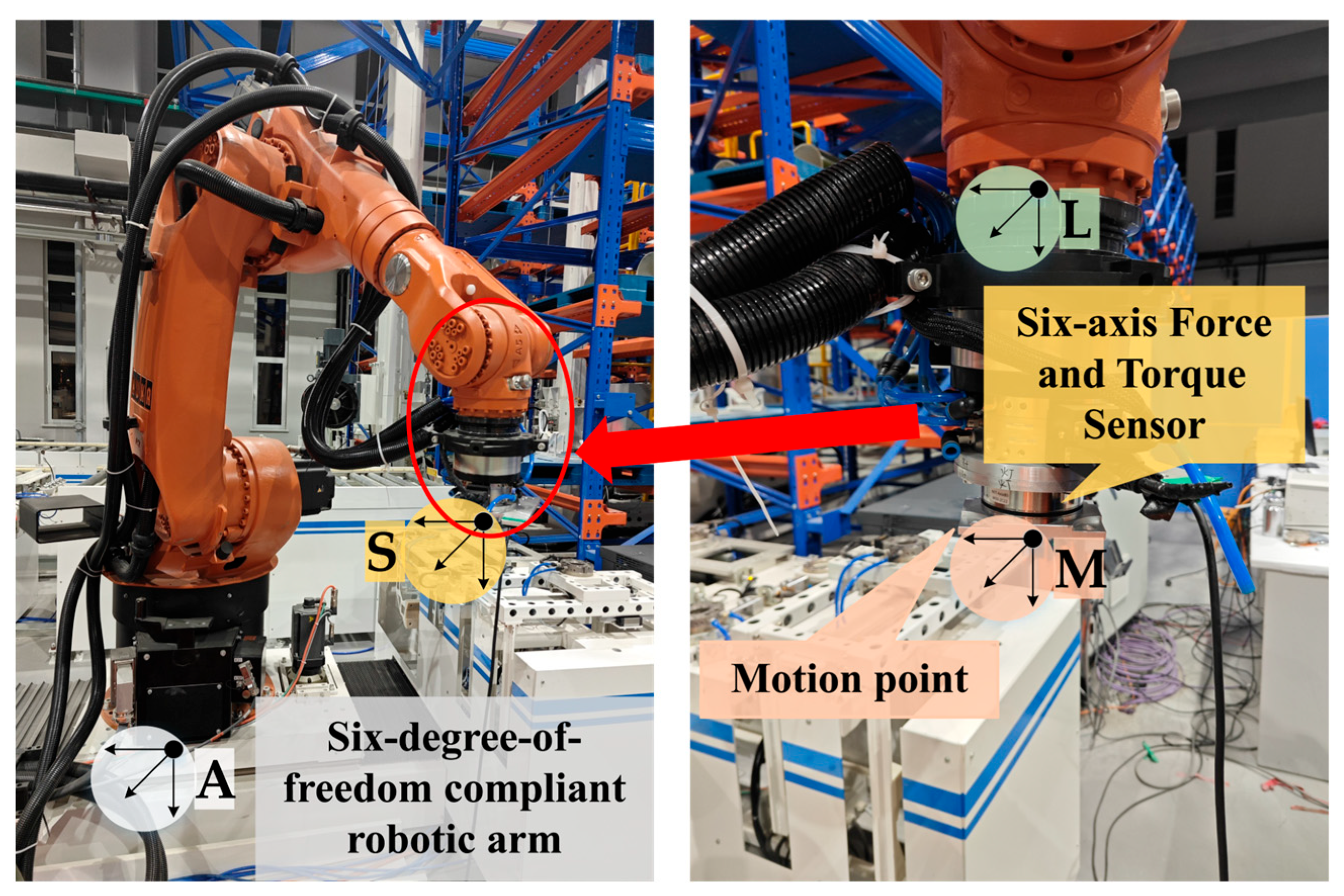
To accurately characterize the human–robot interaction dynamics during operator-guided manual positioning for initial pose calibration, a force-position coupling model must be established between the operator and the manipulator’s end-effector. We employ a Cartesian coordinate frame attached to the end-effector to quantitatively analyze the relationship between force feedback and positional deviation across all six degrees of freedom. The experimental setup is depicted in Figure 1.
A motion point and a six-axis force/torque (F/T) sensor are mounted on the manipulator end-effector. The world coordinate frame {A} serves as the global reference. We define three key frames on the end-effector: the tool frame {L}, the force sensor frame {S} (from which F/T data is acquired), and the motion point frame {M}. For analysis, all force sensor data are transformed into the {M} frame.
The initial state of the model is defined when the operator’s hand engages with the robotic end-effector’s motion point, and the corresponding mathematical model is established. In this state, the operation point coincides with the origin of the manipulator’s end-effector coordinate frame, and the relationship between the applied force and the resultant positional deviation along any coordinate axis is described by the following linear model:
F x , y , z = k F s F 2 ( x , y , z ) t s F 1 ( x , y , z ) t τ .
In the linear model, t denotes the current operating time of the system, s F 2 ( x , y , z ) t represents the current coordinate of the operating point along a given axis of the world coordinate system, and F x , y , z represents the force component along each axis of the world coordinate system. s F 1 ( x , y , z ) t τ denotes the current positional coordinate of the end-effector of the manipulator along each axis of the world coordinate system and corresponds to the position input command received by the manipulator before time τ . k F is the gain coefficient that relates the deviation s F 2 ( x , y , z ) t s F 1 ( x , y , z ) t τ between the operating point of the operator and the position of the end-effector of the manipulator in each direction to the magnitude of the measured force component. The model operates under two core assumptions: first, the positional deviation between the operator’s operating point and the manipulator’s end-effector remains sufficiently small under normal operating forces; second, this deviation is linearly proportional to the force applied to the end-effector. The model and controller design presented in this work are developed and validated within the small-deviation linear regime, as confirmed by the experimental results. Under normal operating conditions, the interaction forces and torques remain bounded. A detailed discussion on the potential implications of nonlinear effects beyond this operational range is provided in Appendix A.
Equation (1) is formulated in the manipulator’s end-effector coordinate frame for computational efficiency. This approach allows the force components measured by the force/torque sensor to be used directly, eliminating the need for additional coordinate transformations.
The torque component experienced along each axis of the manipulator end-effector coordinate system satisfies the functional relationship shown in Equation (2):
T = f k T , r ,
where T is the torque, k T is the transformation coefficient between torque and angle difference, and r is the spatial rotational angle difference about the axis of torque. This equation governs the general relationship between angle and torque. Within the linear regime where angular changes are small, it shares the same form as Equation (1), but with a non-fixed axis of rotation. Our force/torque sensor can directly measure the torque components about the three coordinate axes (X, Y, Z). Consequently, by decomposing the rotational angles onto these three axes, we obtain three separate equations, each describing a rotation about a fixed axis.
T x , y , z = k T r T 2 ( x , y , z ) t r T 1 ( x , y , z ) t τ ,
where r T 2 ( x , y , z ) t denotes the current rotational angle of the operating point on the specified axis in the world coordinate system and T x , y , z denotes the torque components on each axis of the world coordinate system. r T 1 ( x , y , z ) t τ denotes the current rotational angles of the end-effector of the robotic arm about each axis in the world coordinate system. This corresponds to the positional input commands received by the robotic arm prior to time τ . k T is the gain coefficient used to correlate the angular deviation r T 2 ( x , y , z ) t r T 1 ( x , y , z ) t τ between the control point of the operator and the end-effector of the robotic arm in each direction, with the magnitude of the measured torque components.
Equation (1) is the force component of the system equation, and Equation (2) is the torque component of the system equation. Due to the identical dynamics across all six degrees of freedom, a uniform state-space model is applied to each. This allows the design of independent state-feedback controllers tailored to each degree of freedom’s dynamic parameters. The outputs from all six controllers are then combined into a composite command s to achieve compliant robot motion. In this framework, each state vector x 1 and x 2 consists of the positional (or angular) deviation and its derivative:
x 1 = s 2 t s 1 t τ x 2 = s ˙ 2 t s ˙ 1 t τ .
The system input u is defined as the rate of change in the robot’s posture at the current moment:
u = s ˙ 1 t .
The Padé approximation method posits that, under conditions where system delay exists, the current attitude change rate of the robot satisfies the following relationship between the received command signal and the actual attitude:
s ˙ 1 t τ 1 τ s 1 t τ + 1 τ s 1 t .
Therefore, the system state can be expressed as Equation (7). Consequently, the rate of change in the system state is as follows:
x 2 = s ˙ 2 t + 1 τ s 1 t τ 1 τ s 1 t .
Accordingly, the rate of change in the system state is as follows:
x ˙ 1 = x 2 x ˙ 2 = s ¨ 2 t 1 τ 2 s 1 t τ + 1 τ 2 s 1 t 1 τ s ˙ 1 t .
Thus, the state-space representation of the system is established as follows:
x ˙ = A x + B u + D d y = C x ,
where
A = 0 1 0 1 τ , B = 0 1 τ , D = 0 1 , C = k F , T 0 , d = 1 τ s ˙ 2 t + s ¨ 2 t .
This section examines the physical significance of the system output y , which represents the interaction force/torque between the operator and the manipulator end-effector. The disturbance input d models the external influence exerted by the operator on the system. Mathematically, d is formulated as a function of the kinematic state—specifically, the velocity and acceleration—of the operating point. The impact of the operator on both system stability and dynamic response will be analyzed in the subsequent sections.
Remark 1.
During real-time control execution, the system input  u  corresponding to all degrees of freedom is calculated concurrently and synthesized to produce the translational velocity command vector  v t  and the rotational velocity command vector  ω t  for the robot end-effector. A rate-limiting strategy, defined by Equations (11) and (12), is implemented to constrain the rate of change in the commands:
v t = v t v t v v t / v t v v t > v ,
v ˙ t = v ˙ t v ˙ t v ˙ v ˙ t / v ˙ t v ˙ v ˙ t > v ˙ .
In this study, v and v ˙ are defined as the maximum linear velocity and maximum linear acceleration, respectively, that are permissible for the manipulator end-effector.
3. Initial Attitude Calibration Controller Design

This chapter proposes an H∞ state feedback controller for the space docking HIL tests. This controller is designed to address the accuracy and stability risks caused by multi-source uncertainty disturbances in the initial attitude calibration of the simulation, as well as the dynamic balance challenge between safety constraints and intent tracking accuracy during human–machine interaction. The controller is based on the system dynamics model with time-varying delay characteristics constructed in the preceding sections and H∞ robust control theory. This controller has been demonstrated to convert frequency-domain requirements into performance metrics for H∞ control, thereby achieving high-sensitivity tracking of low-frequency intentions and robust suppression of high-frequency disturbances. This is accomplished by constraining the H∞ norm of the closed-loop transfer function. Furthermore, by integrating the Riccati equation within a game theory framework, it ensures strict compliance with interaction force/torque safety threshold constraints under worst-case disturbances while maintaining the robust stability of the closed-loop system. The objective of this design is to achieve a uniform analysis of operator intent, efficient suppression of disturbances, reliable protection of safety boundaries, and high-precision attitude tracking. This design provides a theoretical foundation for subsequent experimental verification. The block diagram of the symmetric human–machine interaction control system based on H∞ control is shown in Figure 2.

3.1. Linear Quadratic Zero-Sum Games

A dual-input control system, comprising control input and disturbance input, has been described in general terms using Equations (13) and (14):
x ˙ = f x + g x u x + k x d x ,
y = h x ,
where the state x t n , output y t p , and sufficiently smooth functions f x t n , g x n × m , k x n × q , h x p × n . This system has two inputs: the control input u x t m and the disturbance input d x t q . In zero-sum games, the control and disturbance are considered as inputs that can be selected by two players to optimize their benefit as described below. Assume f x is locally Lipschitz continuous with f 0 = 0 , implying x = 0 is an equilibrium point of the system.
Define the performance index:
J x 0 , u , d = 0 r x , u , d d t ,
r x , u , d = Q x + u T R u γ H 2 d 2 ,
where R is the symmetric and positive definite control input weighting matrix, Q is the state weighting matrix, and the following holds: Q x = h T x h x 0 , R = R T > 0 . γ * denotes the infimum value of γ H for which the system is stabilizable: γ H γ * 0 . The quantity γ * is termed the H∞ gain. For linear systems, γ * admits an explicit closed-form expression. For nonlinear systems, γ * may exhibit dependence on the operating region where solutions exist.
For fixed feedback policies u x and disturbance policies d x , the value function V is defined as:
V x t , u , d = t Q x + u T R u γ 2 d 2 d τ .
When the value is finite, a differential equivalent to this is the nonlinear zero-sum game Bellman equation:
r x , u , d + V T f x + g x u x + k x d x = 0 ,
V 0 = 0 ,
where V = V / x R n is the (transposed) gradient. The Hamiltonian of dynamics and value function is as follows:
H x , V , u , d = r x , u , d + V T f x + g x u x + k x d x = 0 .
The synthesis of the H∞ state-feedback controller is fundamentally aimed at achieving robust closed-loop stability in the presence of worst-case disturbances and model uncertainties—specifically including those introduced by the Padé approximation of time delays. The successful solution of the Bellman equation yields a value function V x 0 and, critically, generates a corresponding control policy u x . This policy is inherently stabilizing and provides rigorous guarantees of asymptotic stability for the closed-loop system, even when accounting for the uncertainties arising from delay approximation.
For the linear system defined by Equations (9) and (10), substituting Q x = h T x h x 0 into Equations (17) and under the conditions x t R n , the value function assumes an integral form as shown in Equations (21) and (22):
V x t , u , d = 1 2 t x T H T H x + u T R u γ H 2 d 2 d τ ,
V x t , u , d t r x , u , d d τ < 0 ,
where R = R T > 0 and γ H > 0 . Assume that the value is quadratic in the state so that:
V x = 1 2 x T S x ,
for some matrix S > 0 . The matrix S is a symmetric positive definite matrix defined within the framework of linear quadratic zero-sum games to solve for the H∞ state feedback controller. Select state variable feedbacks for the control and disturbance so that:
u = K x ,
d = L x ,
where K and L matrices represent the state feedback gains:
K = k 1 k 2 , L = l 1 l 2 .
Substituting this into Bellman equation gives:
S A B K + D L + A B K + D L T S + H T H + K T R K γ H 2 L T L = 0 .
It has been assumed that the Bellman equation holds for all initial conditions, and the state x t has been canceled. This is a Lyapunov equation for S in terms of the prescribed state feedback policies K and L. If A B K + D L is stable, A , H is observable, and γ H > γ * > 0 then there is a positive definite solution S 0 , and function (26) is the value for the selected feedback gains K and L . This established condition directly links the existence of a solution to the Game Algebraic Riccati Equation (GARE) with the asymptotic stability of the resulting closed-loop system. It thereby provides a concrete and verifiable criterion for ensuring robust stability within our H∞ control framework, forming the cornerstone of our theoretical guarantees.
The stationary point control and disturbance are given by:
u x = R 1 B T S x = K x ,
d x = 1 γ H 2 D T S x = L x .
Substituting these into (27) yields the GARE:
A T S + S A + H T H S B R 1 B T S + 1 γ H 2 S D D T S = 0 .
Assume the matrix B ˜ satisfies the following relation:
B ˜ R 1 B ˜ T = B R 1 B T 1 γ H 2 D D T .
Substituting B from Equation (10) into Equation (31) gives:
B ˜ R 1 B ˜ T = 0 0 0 1 τ 2 1 γ H 2 , B ˜ = 0 ± 1 τ 2 1 γ H 2 .
The Riccati equation is now considered to be the standard Riccati equation:
0 = A T S + S A + Q S B ˜ R 1 B ˜ T S ,
where
Q = H T H = k F 2 0 0 0 .
In H∞ state feedback controller design, the selection of the transformation matrix B ˜ directly governs closed-loop stability. This matrix is hereby redefined as:
B ˜ = 0 ± σ , σ = 1 τ 2 1 γ H 2 > 0 .
This section introduces the B ˜ matrix, which, under the specific matrix coefficients of our model, transforms GARE into standard Riccati equation to simplify the solution process.

3.2. Parameter Tuning

A review of the system’s current state is conducted, with x 1 = s 2 t s 1 t τ representing the deviation between the operating point and the position or angle of the end of the robotic arm. The control input u is defined as the rate of change in the posture of the end of the robotic arm at the current moment. This affects the system through the input matrix B :
x ˙ 2 = 1 τ x 2 + 1 τ u + d .
In instances where the system state component x 1 > 0 , signifying that the operating point is situated in front of the end of the robotic arm in the operating direction, it is imperative to generate a positive acceleration to mitigate position deviation. At this juncture, the control input must satisfy u > 0 , and its dynamic effect is reflected in a negative acceleration component, causing the robotic arm to decelerate. The corresponding state feedback controller can be expressed as:
u = K x = k 1 x 1 k 2 x 2 .
In the event that the system state component x 1 > 0 , it is imperative that the control input satisfy u > 0 . Substitution of this condition into the state feedback controller yields the following result:
u = k 1 x 1 k 2 x 2 > 0 .
Given that the state component x 1 > 0 and x 2 is undetermined, but the dominant term of the control input is k 1 x 1 , it can be deduced that:
k 1 > 0 k 1 < 0 .
In the process of solving the standard Riccati equation, a symmetric positive-definite matrix S > 0 and a state feedback gain matrix are derived:
K = R 1 B ˜ T S .
The state feedback gain matrix is explicitly expressed as follows:
K = k 1 , k 2 = B ˜ T S = 0 , ± σ s 11 s 12 s 21 s 22 = ± σ s 12 , ± σ s 22 .
From this, we can obtain the following:
k 1 = ± σ s 12 .
If matrix B ˜ is 0 σ , then the closed-loop system matrix A c l is given by the following:
A c l = A B ˜ K = 0 1 σ 2 s 12 1 τ σ 2 s 22 .
The characteristic equation of the closed-loop system is given by the following:
det λ I A c l = λ 2 + 1 τ + σ 2 s 22 λ + σ 2 s 12 = 0 .
Stability of the closed-loop system requires all coefficients of the characteristic equation to be positive:
1 τ + σ 2 s 22 > 0 s 12 > 0 .
Here, k 1 = σ s 12 > 0 contradicts Equation (39). If matrix B ˜ is 0 σ , the control gain satisfies k 1 = σ s 12 > 0 , thereby meeting the stability condition. In this scenario, the value of B ˜ results in the state feedback gain k 1 possessing an inherently negative sign, satisfying the physical requirements of the operator-manipulator interaction process. Concurrently, B ˜ also embodies the physical manifestation of the solution to the Riccati equation within the time-delay control system. Mathematically, leveraging the positive definiteness of S naturally leads to k 1 < 0 , consequently achieving strict alignment between the sign of the gain and the physical requirements. Finally, regarding the closed-loop system dynamics:
x ¨ 1 + 1 τ x ˙ 1 + σ k 1 x 1 = 0 .
The positive stiffness term σ k 1 resulting from B ˜ induces an opposing acceleration with respect to the system state component x 1 . Additionally, the energy dissipation term 1 τ x ˙ 1 acts to dampen oscillations. The two terms collectively ensure the asymptotic stability of the system and simultaneously adhere to the laws of dynamics.

4. Experimental Validation

This study validates an H∞ control-based strategy for initial attitude calibration in HIL testing of space docking mechanisms. An experimental platform incorporating a six-axis force/torque sensor and a robotic manipulator was developed to emulate the process wherein an operator guides one docking mechanism to achieve pose alignment with another, thereby accomplishing initial attitude calibration. During the experiments, the interaction forces and torques were recorded in real time by the six-axis force/torque sensor mounted on the robotic end-effector. The force acquisition and robot control cycles were set to 1 ms and 4 ms, respectively. The system and stiffness parameters were configured as follows:
k F , T = 4 , τ = 0.03 , γ H = 1 , R = 1 .
The LQR algorithm is employed to solve the standard Riccati equation, thereby obtaining the state feedback controller parameter K = 4       0.1206 . This ensures that the closed-loop system satisfies the stability conditions.

4.1. Calibration Results

The calibration results are displayed in Table 1.
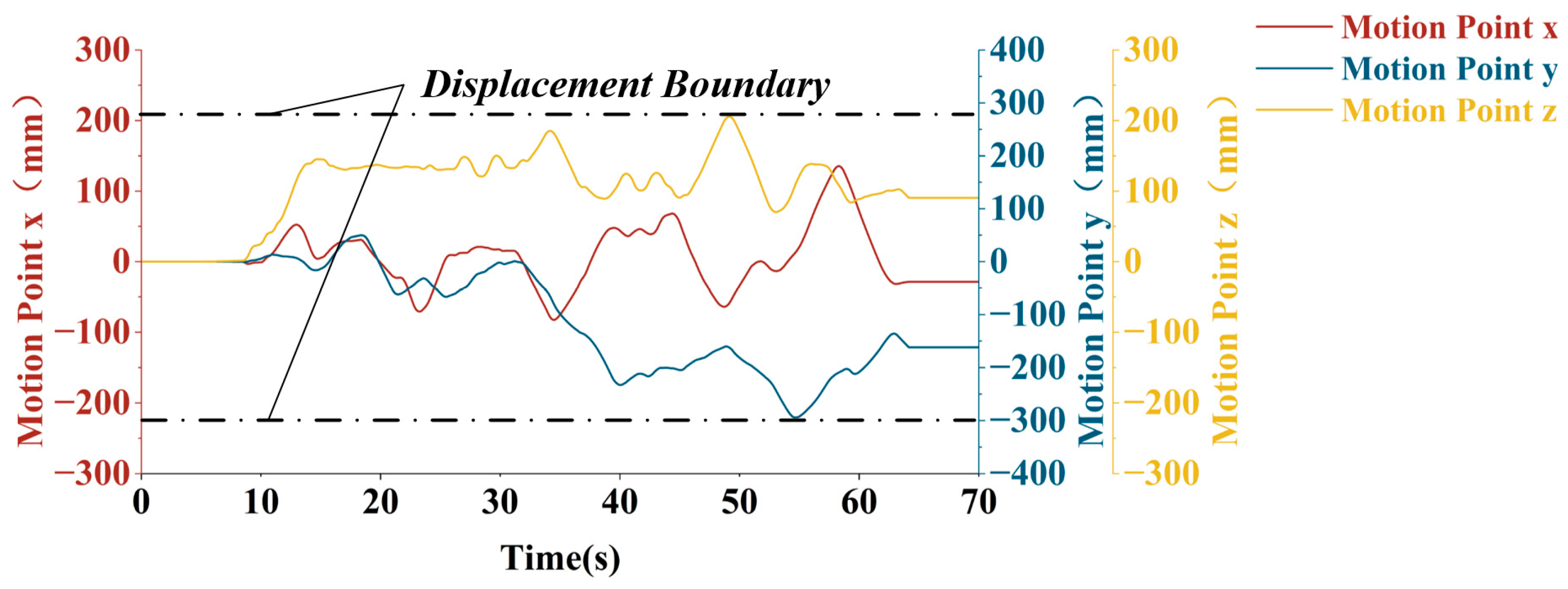
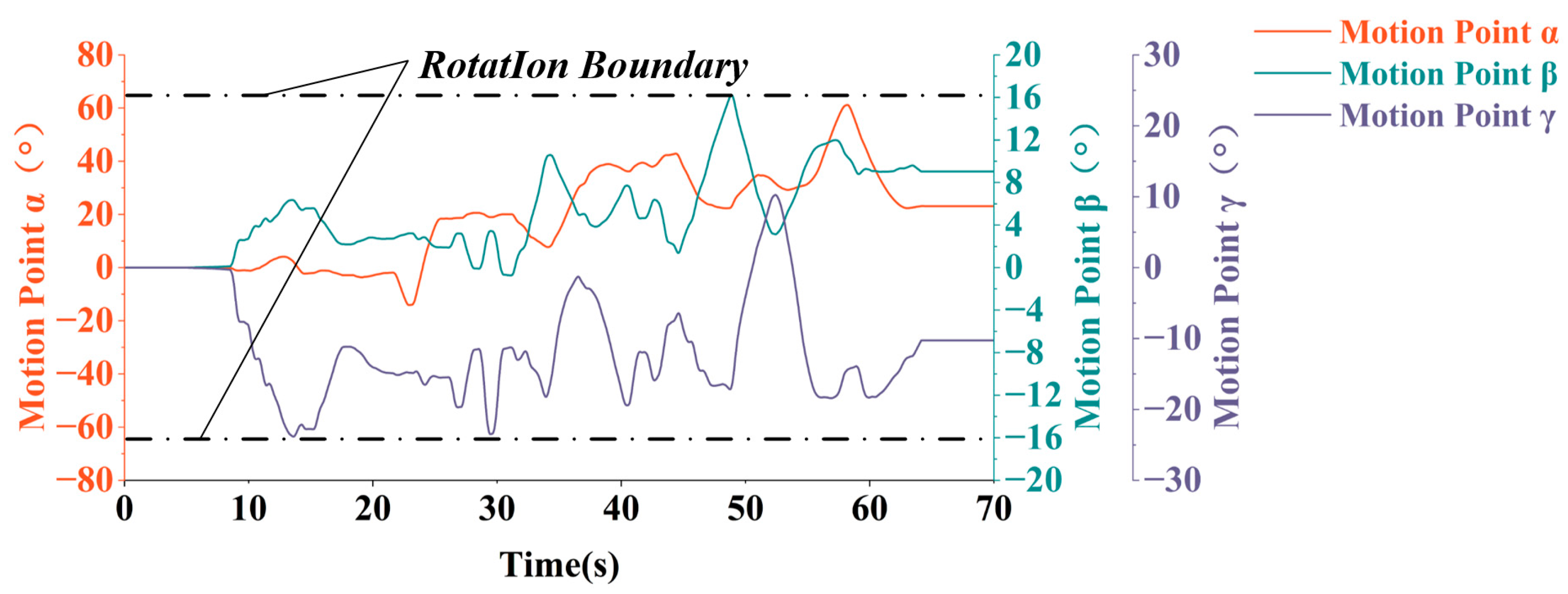
The displacement and rotation angle responses of the manipulator end-effector are illustrated in Figure 3 and Figure 4, respectively. As illustrated in Figure 3, the displacement trajectories along the x, y, and z directions demonstrate continuous and smooth variation trends, devoid of any discernible jumps or hysteresis phenomena. Notably, the minimal deviations in translational and rotational axes (Table 1) confirm that the two docking mechanisms ultimately achieve spatial pose symmetry (zero pose)—the core target of goal symmetry—with their coordinate systems aligned to a degree that meets HIL test requirements. As illustrated in Figure 4, the rotation angles about the α, β, and γ axes also demonstrate optimal tracking performance. The apparent randomness in the curves results from intentionally random guidance inputs applied during testing to verify system stability. These trajectories document the system’s successful attainment of predetermined targets under “process-random, goal-defined” human guidance, thereby demonstrating its robustness.

4.2. Stability Analysis of the Calibration Process

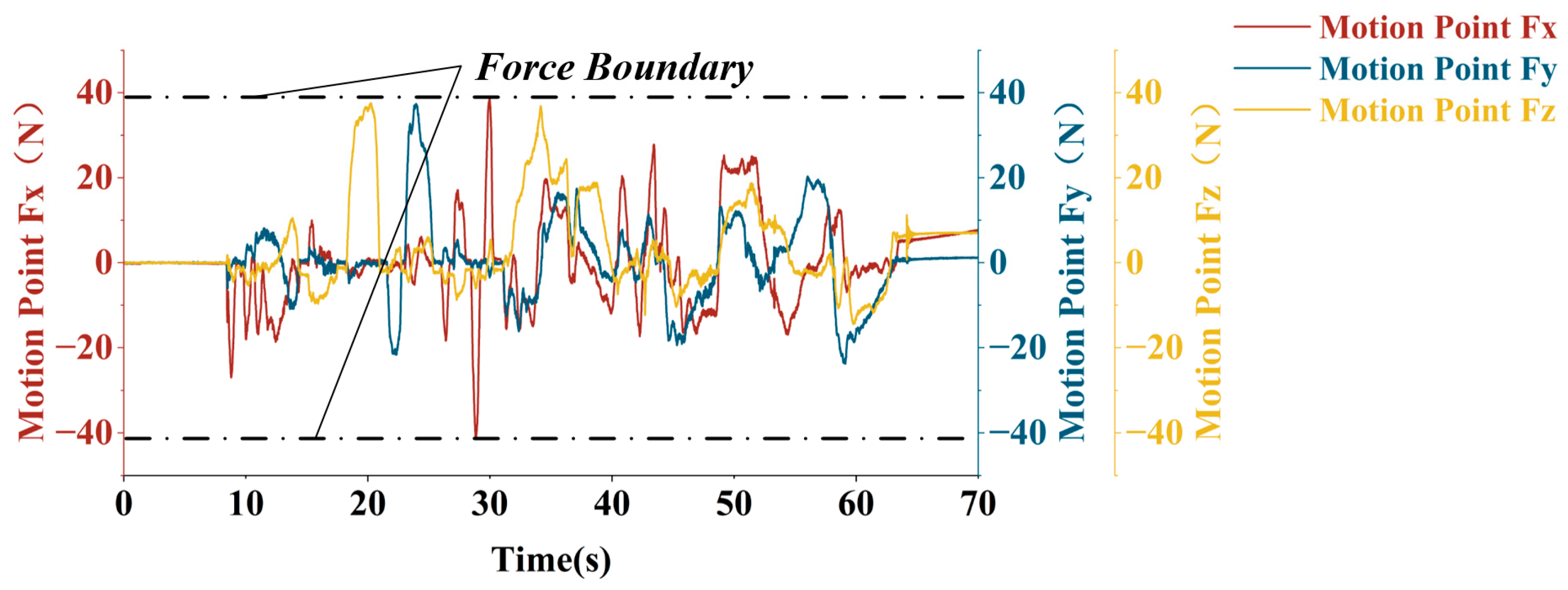
During the experiment, real-time force and torque data at the end-effector—measured by a six-axis force/torque sensor—are shown in Figure 5 and Figure 6. The results demonstrate that the H∞ controller suppresses force and torque oscillations, maintaining both within safe limits and confirming precise force control capability. Specifically, the force/torque signals exhibit minimal asymmetry between the operator’s applied force (master side) and the robotic arm’s feedback force (slave side), verifying that the H∞ control effectively reconstructs interactive symmetry: delays and disturbances are compensated to ensure smooth, force-matched human–robot interaction, with no obvious lag between operator traction intent and robotic motion response.
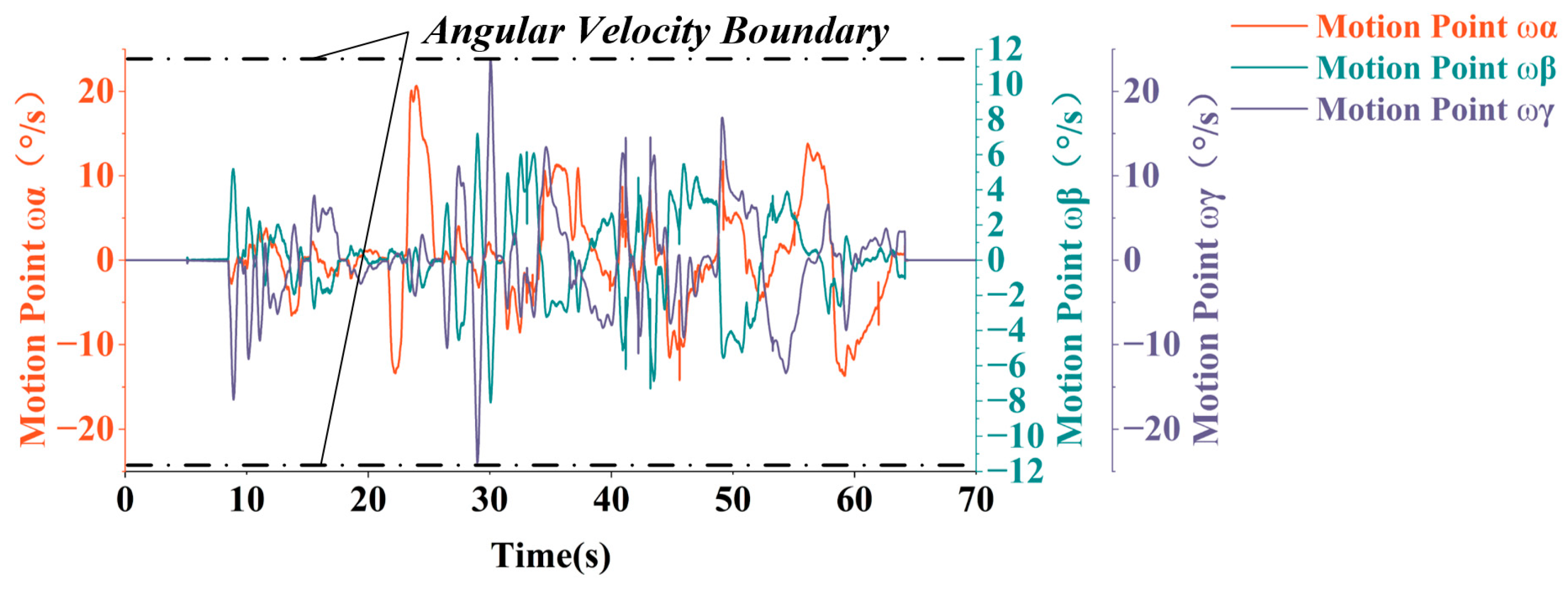
The translational velocity remains within ±30 mm/s, and the rotational angular velocity stays below 30°/s. As shown in Figure 7 and Figure 8, the velocity profiles exhibit smooth variation without abrupt changes or high-frequency oscillations. These results confirm that the controller reduces phase lag caused by system delays, resulting in smooth end-effector motion. This smooth velocity synchronization further enhances interactive symmetry by eliminating motion asynchrony between the operator and robotic arm, avoiding calibration errors or operator discomfort caused by asymmetric response.
Force/torque and motion analysis confirmed full system stability during tests. Even under external disturbances (e.g., environmental interference, minor parameter perturbations), the end-effector force/torque quickly stabilized, and motion remained synchronous without divergence. These results validate the effectiveness of symmetric optimization: the game-theoretic Riccati equation solution balances the conflicting demands of tracking accuracy (e.g., smooth trajectory following in Figure 3 and Figure 4) and safety constraints (e.g., force/torque limits in Figure 5 and Figure 6), achieving an optimal symmetric equilibrium—neither sacrificing accuracy for safety nor compromising safety for speed. The system also maintained coordination between motion and force parameters with no safety violations, demonstrating the H∞ controller’s ability to balance disturbance rejection, delay compensation, and safety. This supports its applicability to initial attitude calibration in space docking HIL testing, as it simultaneously realizes goal symmetry, interactive symmetry, and symmetric optimization.
The quantitative data from the experiments provide concrete evidence of the system’s stability, safety, and tracking accuracy. In this compliant interaction architecture, the interaction force/torque intrinsically reflects the tracking performance, where minimal force/torque values indicate precise motion synchronization. Throughout the calibration process, the interaction forces and torques at the end-effector, as recorded in Figure 5 and Figure 6, were rigorously bounded within ±40 N and ±6 Nm, respectively. These bounded values, well below the predefined safety thresholds, confirm that the tracking error was maintained within an acceptable range while ensuring operational safety. Concurrently, the motion profiles depicted in Figure 7 and Figure 8 show that the translational and rotational velocities were consistently maintained within ±30 mm/s and ±30°/s. The smoothness of these profiles, characterized by the absence of overshoot and high-frequency oscillations, serves as a key indicator of stable closed-loop behavior. The combination of these bounded physical metrics conclusively demonstrates that the proposed H∞ controller successfully guaranteed a stable, safe, and accurate human–robot interaction.

5. Discussion

In this chapter, an analysis is presented of the impact of variations in system parameters upon system performance. Firstly, the influence of delay τ , the H-infinity control parameter γ , and weight R upon control gain was examined. Subsequently, the focus was directed towards the analysis of the effect of delay on the control efficacy of the system. In conclusion, a comparison was made between the performance of the H-infinity-based state feedback controller proposed in this study and that of the classical PID controller. It is evident from the comprehensive analysis presented in this paper that the proposed methodology demonstrates notable robustness and attains satisfactory levels of control performance.

5.1. Discussion of System Parameters

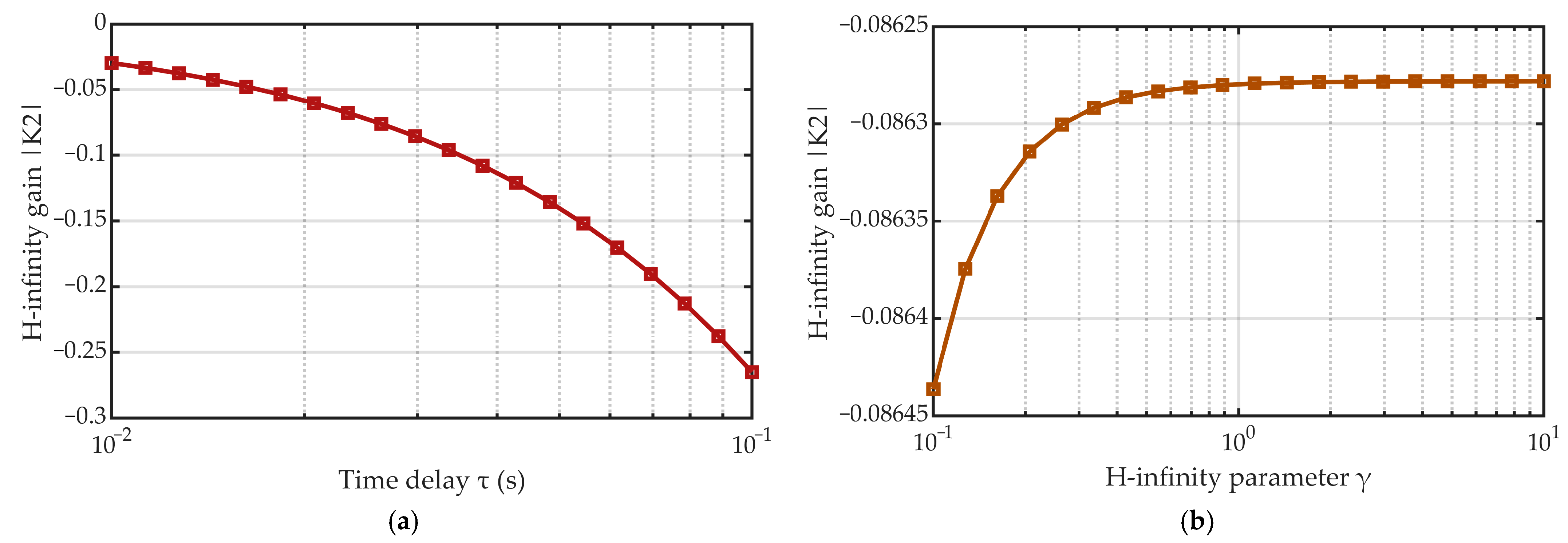
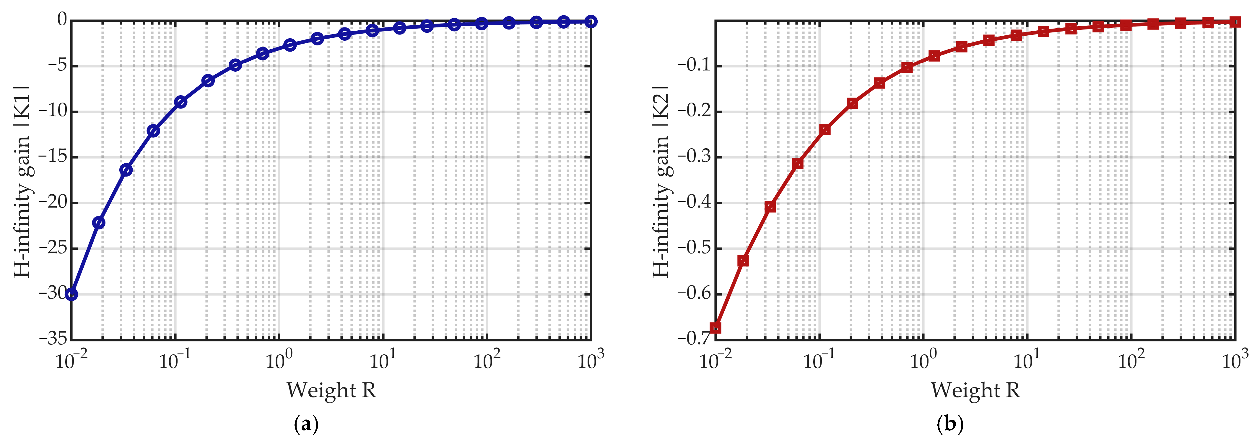
It is evident that the parameters τ , γ and R exert a significant influence on the gain of the H-infinity state feedback controller, as designed in this paper. In this section, an analysis is conducted to ascertain the impact of variations in these three variables upon the gain solution results. The gain K is a vector comprising two components, K 1 and K 2 . As τ and γ exert negligible influence on the value of the component K 1 , the present analysis of τ and γ focuses solely on their effect upon K 2 . The ensuing outcome is illustrated in the accompanying Figure 9.
As demonstrated in Figure 10, the influence of γ on gain K 2 is significantly less than that of τ . The diagram provides a visual representation of the effect of weight R on the gain vector. As demonstrated by the figure, the weight R exerts a substantial influence on the system’s control gain.

5.2. The Present Study Investigates the Impact of Time Delay on System Stability

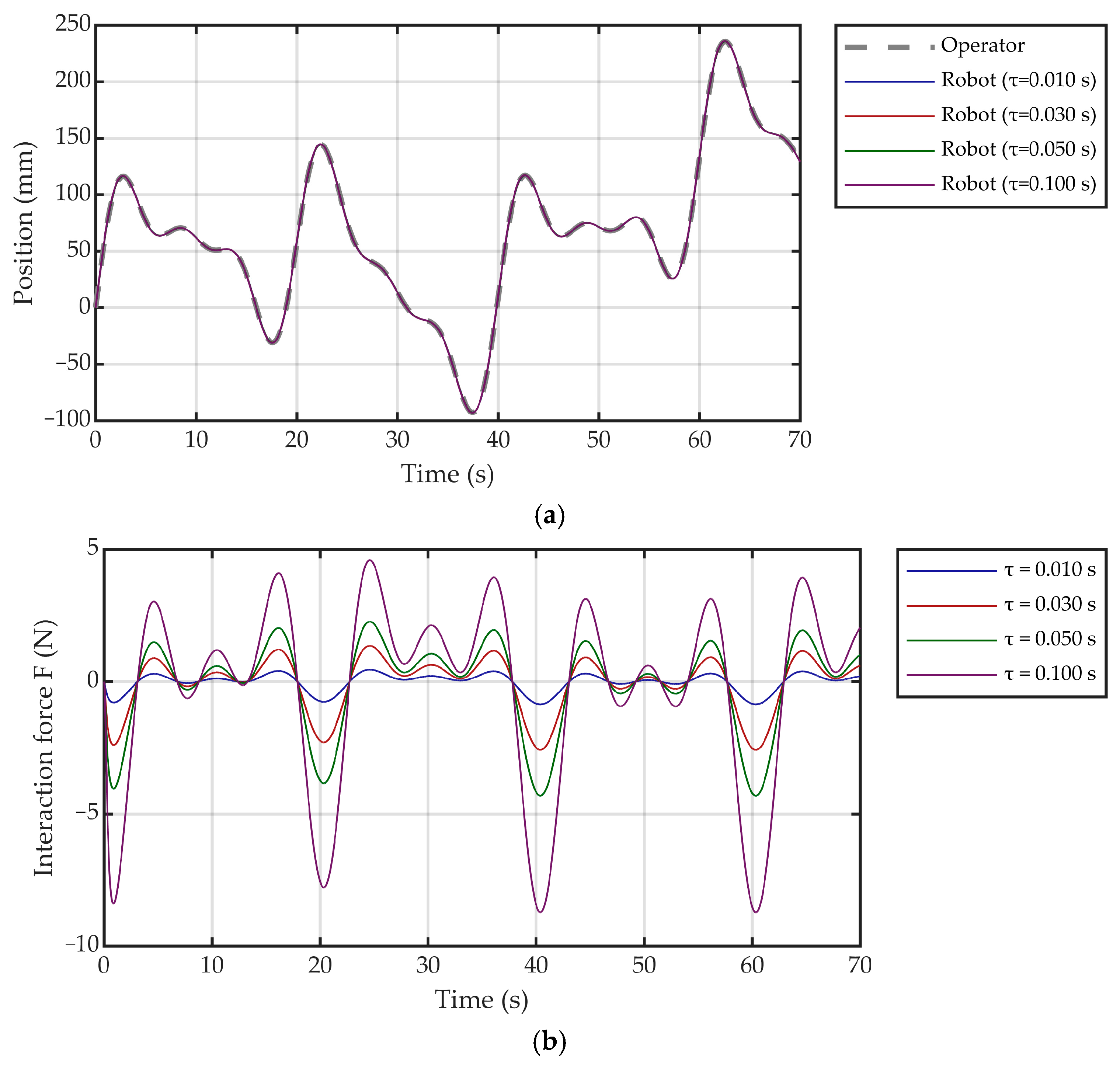
In systems incorporating delays, it is imperative to analyze the impact of these delays on system stability and control performance. This section will draw parallels between the effects of varying delays on system control performance. It is important to note that the control gains were calculated based on actual delays. To do this, simulations were conducted under constant control gain conditions across different delays. This was performed instead of deriving distinct gains for each delay. This analytical approach is more closely aligned with real-world scenarios in which hardware states change without operator awareness. The impact of varying delays on system control performance is illustrated in Figure 11.
As illustrated in Figure 11, a randomly varying smooth curve has been designed to represent the operator’s intent. The robot is capable of tracking the operator’s intent. The system’s output has been represented by a curve, which has been plotted. The system output is then utilized to evaluate the effectiveness of human–machine interaction. It is evident that as latency increases, the system’s interaction performance deteriorates.
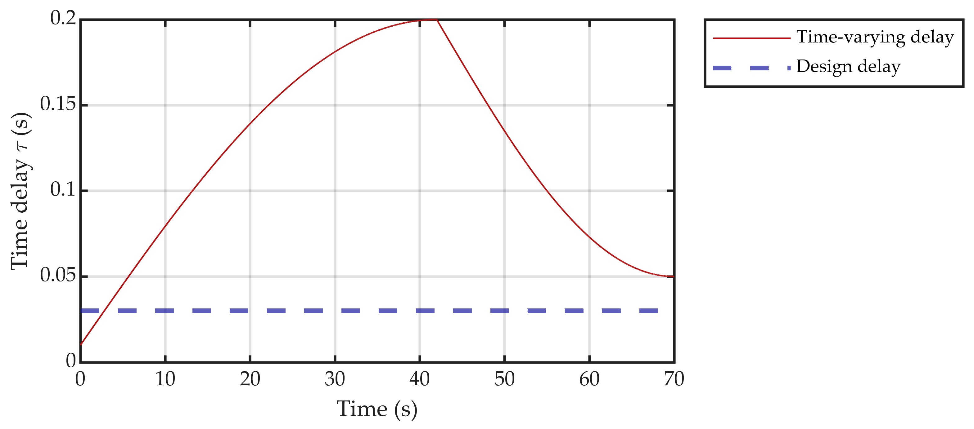
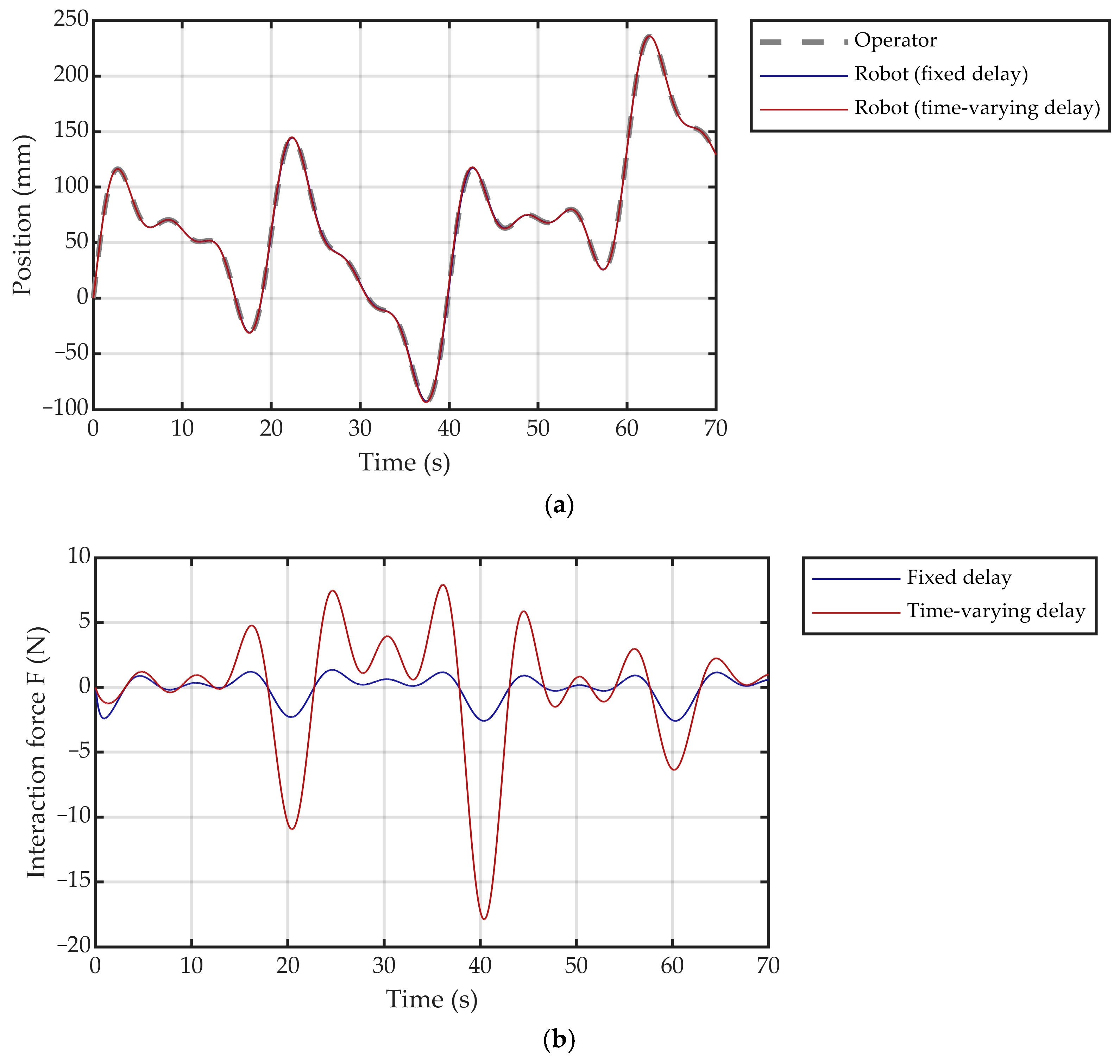
The preceding analysis is predicated on the assumption of constant delay over a specified period. Should the system’s delay vary during a single operation—a change unforeseen during controller design—would our system’s robustness accommodate such circumstances? This scenario bears a closer resemblance to an exceptionally prolonged operation in which system parameters shift, thereby necessitating the controller’s robustness to compensate. The development of a delay variation curve is illustrated in Figure 12.
In the context of variable latency, the system’s efficacy in recognizing and executing the operator’s intentions was analyzed, as depicted in Figure 13.
Research has confirmed that increased system latency leads to degraded human–machine interaction quality, which aligns with our previous analytical findings. Simultaneously, addressing the inherent time delays represents a fundamental challenge in achieving seamless and synchronous human–machine interaction during initial attitude calibration. To systematically resolve and compensate for these delays in controller design, this paper employs the Padé approximation method to incorporate pure time delay elements into the linear time-varying state-space model of the system. The advantages and limitations of this approach, along with our corresponding mitigation strategies, are detailed below:
Advantage: The primary benefit of using Padé approximation lies in its ability to transform a system with pure time delay into a finite-dimensional, linear time-invariant (LTI) state-space representation. This transformation is crucial for controller design, as the resulting model offers significantly higher computational efficiency for real-time implementation on our HIL test platform compared to directly handling the original irrational transfer function or delay differential equations.
Disadvantage and Mitigation Strategy: The key limitation of this method is the introduction of model-plant mismatch. Since Padé approximation inherently provides only an estimate of the true delay, approximation errors are inevitable. The finite-dimensional LTI model cannot perfectly capture the infinite-dimensional characteristics of the original time-delay system across all frequency ranges. Consequently, a controller designed solely based on this approximate model may lack robustness and could exhibit performance degradation or even instability when applied to the actual system.
This inherent limitation precisely justifies our integration of Padé approximation with the H∞ robust control framework. Rather than treating the approximated model as an exact representation, the H∞ controller is explicitly designed to account for and maintain robustness against such model uncertainties—including Padé approximation errors, unmodeled dynamics, and external disturbances. Thus, the potential drawback of model inaccuracy is directly addressed and mitigated through the robustness of our control strategy.
In summary, while Padé approximation introduces simplification errors, its value in providing a tractable LTI model remains indispensable. Its integration with H∞ control forms a coherent design methodology: the approximation enables practical controller synthesis, while the robust control framework ensures stability and performance despite model imperfections.

5.3. Comparison of H∞ Control with Classical PID Control

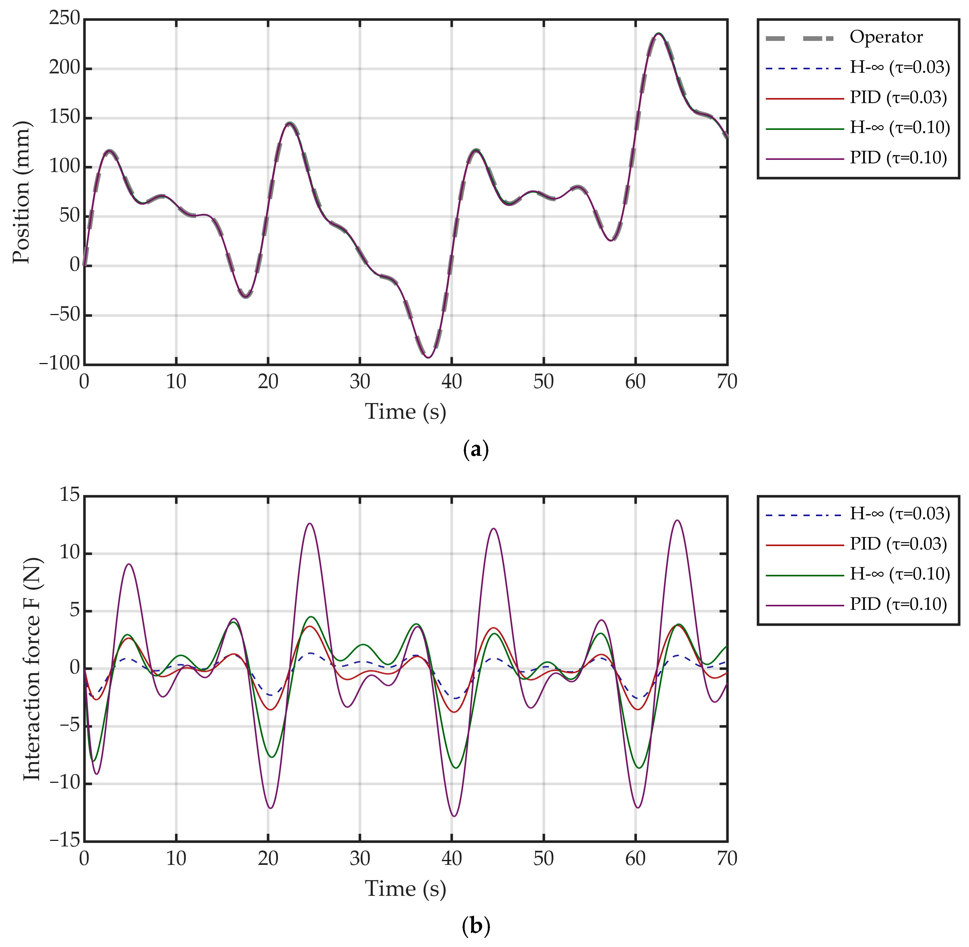
The present paper puts forward a robust control method based on H-infinity. In this section, a comparison is drawn between the proposed control method and a classical PID controller. The operator’s intent employs the same smoothing curve as in delay analysis. The performance of both control methods is compared under two delay conditions. As demonstrated in the accompanying Figure 14, both control methodologies demonstrate a decline in efficacy as delay increases for different delay values. In both delay conditions, the proposed control method has been shown to be the optimal solution.

6. Conclusions

This paper proposes an H∞ robust control-based human–robot collaborative strategy to achieve accurate and safe initial attitude calibration in space docking HIL testing. The approach introduces a dynamic model incorporating system delays and an H∞ controller that integrates frequency-domain shaping with game-theoretic optimization, with the core objective of realizing three essential forms of symmetry. The method attains goal symmetry by enabling precise spatial alignment between the active and passive docking mechanisms, ensuring their coordinate systems achieve complete congruence or mirror symmetry—a fundamental prerequisite for reliable HIL testing. Furthermore, it reconstructs interactive symmetry through systematic delay compensation and disturbance attenuation, maintaining smooth, force-matched, and lag-free collaboration between the operator’s guidance and the robotic arm’s response. Additionally, optimization symmetry is realized via the solution of a game-theoretic Riccati equation, which balances the competing demands of tracking accuracy and force/torque safety constraints to attain an optimal equilibrium.
Key experimental outcomes include accurate tracking of operator intent under multi-source disturbances, strict enforcement of interaction force/torque limits, effective compensation of system delays, and guaranteed robust stability. The method eliminates dependence on external calibration instruments and demonstrates superior performance in both disturbance rejection and safety-aware control. By providing an external-hardware-free online calibration framework that embodies these symmetric properties, this study extends the theoretical foundation of HIL testing for space docking mechanisms and offers practical support for applications such as on-orbit servicing and deep-space equipment verification.
Future research will extend the proposed framework to more complex HIL scenarios, including in-space assembly and high-precision industrial robotic tasks. Specific efforts will focus on scaling the method to multi-level HIL systems with coordinated multi-robot subsystems. Additional exploration will target its applicability in large-scale space infrastructure construction and multi-stage industrial manufacturing processes, where simultaneous calibration of multiple docking interfaces or assembly stations is essential. These investigations will further validate the generality and scalability of the symmetric control framework while addressing increasingly sophisticated engineering demands in advanced aerospace and industrial systems.

Author Contributions

Conceptualization, X.Z.; Methodology, X.Z.; Validation, X.Z.; Formal analysis, Z.J. and Y.H.; Resources, Z.J., Y.H. and Z.Z.; Data curation, Y.T.; Writing—original draft, X.Z. and Y.T.; Writing—review & editing, X.Z. and Y.T.; Supervision, Z.J. and Y.H.; Project administration, Y.H. and Z.Z.; Funding acquisition, Z.J. and Y.H. All authors have read and agreed to the published version of the manuscript.

Funding

This research was funded by the nsfc, grant number 52575012; the Liaoning Provincial Natural Science Foundation, grant number 2025-MS-084; and the Youth Program of the Basic Research Plan, Shenyang Institute of Automation, Chinese Academy of Sciences, grant number 2023JC1K11.

Data Availability Statement

All data generated or analyzed during this study are included in the manuscript. No additional external data were used.

Conflicts of Interest

The authors declare no conflicts of interest.

Abbreviations

The following abbreviations are used in this manuscript:
HILHardware-in-the-Loop
LTILinear time-invariant
GAREGame Algebraic Riccati Equation
6-DOFSix-degree-of-freedom

Appendix A

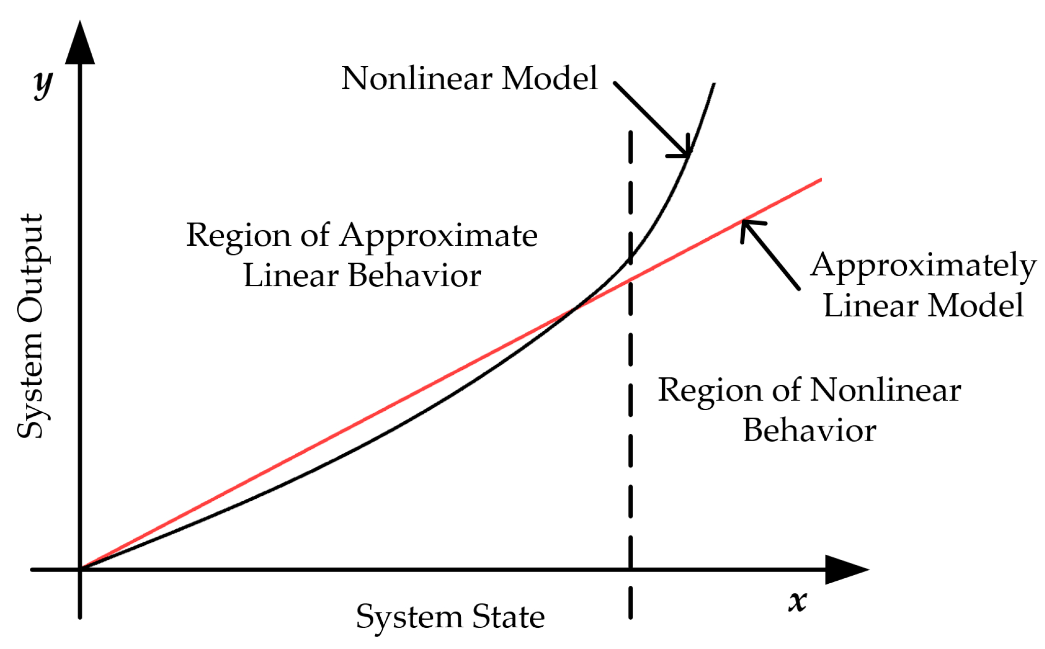
The present study examines the operational behavior of systems where the output is a linear function of the state within a certain range. In circumstances where the system’s actual operating range enters a nonlinear region, it becomes imperative to undertake modifications to certain aspects of the controller design. A recognizable manifestation of nonlinearity occurs when minor changes in the system state cause the output to increase rapidly, exhibiting exponential growth or higher-order polynomial behavior, among other forms.
As demonstrated in Figure A1, when the state values are confined to a relatively narrow range, it is possible to approximate them using a linear model. However, when state changes exceed a certain threshold, the system output increases rapidly, at which point the linear model exhibits a significant deviation. In the case of the nonlinear state illustrated by the curve, it is possible to approximate its description using a nonlinear model.
F x , y , z = k F 1 s F 2 s F 1 + k F 2 s F 2 s F 1 3 s F 2 s F 1 < s 0 k F 3 s F 2 s F 1 s 0 + k F 4 s F 2 s F 1 s 0 3 + F 0 s F 2 s F 1 s 0
The incorporation of cubic terms in this nonlinear model will exert a direct influence on the Q x in performance metrics, the r x , u , d in Bellman’s equation, and the form of the value function.
Figure A1. Linear and nonlinear behavior intervals of the system output versus the system state.
Symmetry 17 01922 g0a1
In the context of the performance indicator function r x , u , d , the occurrence of nonlinearity in h x gives rise to the following implications:
Q x = h 2 x
Consequently, this will render r x , u , d no longer a quadratic form of the state, but rather a cubic form.
In the context of nonlinear systems, quadratic value functions are inadequate in accurately capturing the system’s value characteristics. Consequently, these functions must be extended to more general nonlinear forms to ensure adequate description.
V x = 1 2 x T S x + V n o l i n e a r x
In this context, the symbol, V n o l i n e a r x , denotes the nonlinear term employed to characterize the system’s nonlinear value properties. Furthermore, the value function may be directly solved via the nonlinear Hamilton–Jacobi–Bellman equation—a core tool for handling optimal control/differential games in nonlinear systems, which does not require the “quadratic assumption” on the form of the value function. In nonlinear models, both core components of the Bellman equation undergo transformation: the nonlinearity of the performance metric assumes a “higher-order polynomial form”; the gradient of the value function is no longer a linear function of S x , but rather the gradient of a nonlinear function. Consequently, the Bellman equation for nonlinear systems must be formulated as a nonlinear Hamilton–Jacobi-Bellman equation, the structure of which differs fundamentally from that of the “linear Hamilton–Jacobi-Bellman”. It is evident that, under the assumption of linear systems and a quadratic value function, the derived Riccati equation for the game is no longer applicable. The employment of the nonlinear HJB equation is imperative in this context:
min u max d r x , u , d + V T f x + g x u x + k x d x = 0
In summary, nonlinear characteristics exert a systemic influence on the core equations of the system. The comparison between the “linear form” and “nonlinear form” of each equation is summarized in Table A1.
Table A1. Comparison between the “linear form” and “nonlinear form” of each equation.
Affected EquationsOriginal Form (Linear Model)Changes in Nonlinear Models
Output Equation y = h x Linear C x Nonlinear h x = k 1 x 1 + k 3 x 1 3
Performance Index r x , u , d Quadratic FormHigh-order Polynomial
Value Function V x Quadratic Form 1 2 x T S x Nonlinear Function ( V n o l i n e a r x )
Bellman EquationLinear HJBNonlinear HJB
Riccati EquationLinear ARENot Applicable, Need to Solve Nonlinear HJB
In practice, the system output is used to evaluate the effectiveness of human–machine interaction and to discern operator intent. Actual operational data demonstrate that the system does not readily enter nonlinear regimes, thereby confirming the stability and feasibility of the proposed approach. Moreover, even if the system were to enter a nonlinear regime, human–machine interaction performance is more effectively assessed using linear criteria. This is because, for identical outputs, the linear model corresponds to a larger state variation. Should the state change evaluated by the linear model satisfy the assessment criteria, evaluation based on a nonlinear model would exhibit even better compliance with the standards. In the context of operator intent recognition, the linear model has been shown to amplify the operator’s intent, thereby facilitating more efficient identification. The validity of this analysis is further supported by empirical operational results.

References

  1. Wu, S. Application status and development trend of hardware-in-the-loop simulation system. Ind. Instrum. Autom. 2016, 5, 16–20. [Google Scholar]
  2. Wang, Y.; Meng, L.; Xu, X.; Niu, Y.; Qi, K.; Bian, W.; Yang, Q.; Liu, H.; Jia, J.; Wang, J. Research on Semi-Physical Simulation Testing of Inter-Satellite Laser Interference in the China Taiji Space Gravitational Wave Detection Program. Appl. Sci. 2021, 11, 7872. [Google Scholar] [CrossRef]
  3. Du, R.; Liao, W.; Zhang, X. Optimal Maneuver Strategy to Improve the Observability of Angles-Only Rendezvous. J. Syst. Eng. Electron. 2023, 34, 1020–1032. [Google Scholar] [CrossRef]
  4. Zhang, H.; Wang, M.; Deng, W.; Zhao, J.; Zhou, J.; Ma, X.; Yao, L.; Wang, M. Semi-Physical Simulation Optimization Method for Bolt Tightening Process Based on Reinforcement Learning. Machines 2022, 10, 637. [Google Scholar] [CrossRef]
  5. Hu, H.; Cheng, Y.; Jiang, B.; Li, W.; Guo, K. Missile Fault Detection and Localization Based on HBOS and Hierarchical Signed Directed Graph. Aerospace 2024, 11, 679. [Google Scholar] [CrossRef]
  6. Zhang, H.; Wang, M.; Li, Z.; Zhou, J.; Zhang, K.; Ma, X.; Wang, M. Semi-Physical Simulation of Fan Rotor Assembly Process Optimization for Unbalance Based on Reinforcement Learning. Aerospace 2022, 9, 342. [Google Scholar] [CrossRef]
  7. Hao, Y.; Zhao, S.; Wu, G.; Chen, H.; Li, R. Zero calibration method of maser semi-active guidance hardware-in-the-loop simulation system. Laser Infrared 2023, 53, 97–100. [Google Scholar]
  8. Ma, K.; Ren, C.; Zhang, Y.; Chen, Y.; Chen, Y.; Zhou, P. A New Vibration-Absorbing Wheel Structure with Time-Delay Feedback Control for Reducing Vehicle Vibration. Appl. Sci. 2022, 12, 3157. [Google Scholar] [CrossRef]
  9. Chan, L.; Liu, Y.; Huang, Q.; Wang, P. Robust Adaptive Observer-Based Predictive Control for a Non-Linear Delayed Bilateral Teleoperation System. IEEE Access 2022, 10, 52294–52305. [Google Scholar] [CrossRef]
  10. Baez-Hernandez, J.A.; Velasco-Villa, M.; Mondie, S. Non-Linear Prediction-Based Trajectory Tracking for Non-Holonomic Mobile Robots. IEEE Access 2023, 11, 124265–124277. [Google Scholar] [CrossRef]
  11. Zhang, E.; Huang, Q.; Wei, Z.; Fan, X.; Su, S. H∞ Robust Fault-Tolerant Control of a Six-Rotor UAV Containing Sensor Faults and Actuator Non-Affine Faults. IEEE Access 2023, 11, 138773–138787. [Google Scholar] [CrossRef]
  12. Gu, B.Y.; Cong, J.; Zhao, J.; Chen, H.; Golshan, M.F. A novel robust finite time control approach for a nonlinear disturbed quarter-vehicle suspension system with time delay actuation. Automatika 2022, 63, 627–639. [Google Scholar] [CrossRef]
  13. Zheng, Y.-G.; Zhao, Y.-Y. Robust H stabilization for systems with uncertain input time-delay. J. Frankl. Inst.-Eng. Appl. Math. 2024, 361, 107223. [Google Scholar] [CrossRef]
  14. Zhang, Y.; Ma, H.; Wang, S.-Q.; Xu, J.; Su, H.; Zhang, J. Adaptive neural network H control for offshore platform with input delay and nonlinearity. IET Control Theory Appl. 2024, 18, 384–398. [Google Scholar] [CrossRef]
  15. Li, Z.; Wu, M.; Song, K. An EMU Rectifier Control Approach for Low-Frequency Oscillation Suppression Based on H∞ Robust Control. In Proceedings of the 2024 IEEE 6th Advanced Information Management, Communicates, Electronic and Automation Control Conference (IMCEC), Chongqing, China, 24–26 May 2024; pp. 1231–1235. [Google Scholar]
  16. Li, X.; Xia, C.; Li, H. Research on Bidirectional Wireless Charging System for Electric Vehicles Based on H∞ Robust Control. In Proceedings of the 2024 IEEE 10th International Power Electronics and Motion Control Conference (IPEMC2024-ECCE Asia), Chengdu, China, 17–20 May 2024; pp. 383–388. [Google Scholar]
  17. Haddadin, S.; Krieger, K.; Albu-Schaeffer, A.; Lilge, T. Exploiting Elastic Energy Storage for “Blind” Cyclic Manipulation: Modeling, Stability Analysis, Control, and Experiments for Dribbling. IEEE Trans. Robot. 2018, 34, 91–112. [Google Scholar] [CrossRef]
  18. Lopes, A.; Almeida, F. A force-impedance controlled industrial robot using an active robotic auxiliary device. Robot. Comput. Integr. Manuf. 2008, 24, 299–309. [Google Scholar] [CrossRef]
  19. Zhang, K.; Xu, J.; Chen, H.; Zhao, J.; Chen, K. Jamming Analysis and Force Control for Flexible Dual Peg-in-Hole Assembly. IEEE Trans. Ind. Electron. 2019, 66, 1930–1939. [Google Scholar] [CrossRef]
Figure 1. 6-DOF compliant robotic arm.
Symmetry 17 01922 g001
Figure 2. Block diagram of a symmetric human–robot interaction system based on H∞ control.
Symmetry 17 01922 g002
Figure 3. Displacement of the end point of the robotic arm.
Symmetry 17 01922 g003
Figure 4. Rotation angle of the end point of the robotic arm.
Symmetry 17 01922 g004
Figure 5. Three-dimensional force at the end point of a robotic arm.
Symmetry 17 01922 g005
Figure 6. Three-dimensional torque at the end point of a robotic arm.
Symmetry 17 01922 g006
Figure 7. Velocity of the end point of the robotic arm.
Symmetry 17 01922 g007
Figure 8. Rotational angular velocity of the end point of the robotic arm.
Symmetry 17 01922 g008
Figure 9. Influence of system parameters τ and γ on controller gain K 2 . (a) Effect of time delay τ on gain K 2 . (b) Effect of H∞ parameter γ on gain K 2 .
Symmetry 17 01922 g009
Figure 10. Influence of system parameters R on controller gain K 1 and K 2 . (a) Effect of weight R on gain K 1 . (b) Effect of weight R on gain K 2 .
Symmetry 17 01922 g010
Figure 11. Impact of different delays. (a) Impact of different delays on system control performance. (b) The impact of different delays on the interaction force.
Symmetry 17 01922 g011
Figure 12. Delay variation curve.
Symmetry 17 01922 g012
Figure 13. Impact of varying delays. (a) Impact of varying delays on system control performance. (b) The impact of varying delays on the interaction force.
Symmetry 17 01922 g013
Figure 14. Comparison of H∞ control and PID control. (a) Comparison of H∞ control and PID control performance under different delays. (b) Interaction forces of H∞ control and PID control under different delays.
Symmetry 17 01922 g014
Table 1. Calibration results.
Axisx/mmy/mmz/mm
Data−28.53−161.7290.50
Axisα/°β/°γ/°
Data23.1279.035−10.282
Disclaimer/Publisher’s Note: The statements, opinions and data contained in all publications are solely those of the individual author(s) and contributor(s) and not of MDPI and/or the editor(s). MDPI and/or the editor(s) disclaim responsibility for any injury to people or property resulting from any ideas, methods, instructions or products referred to in the content.