Article

Multi-Physics Coupling Mechanism of the Dynamic Sealing Performance of the O-Ring at the Neck of a Type IV Hydrogen Storage Cylinder Under Linearly Decreasing Filling Conditions

School of Mechanical Engineering, Inner Mongolia University of Science and Technology, Baotou 014000, China
*
Author to whom correspondence should be addressed.
Symmetry 2025, 17(11), 1921; https://doi.org/10.3390/sym17111921
Submission received: 14 October 2025 / Revised: 3 November 2025 / Accepted: 6 November 2025 / Published: 10 November 2025

Abstract

To address the degradation of O-ring material properties and reduced dynamic seal reliability caused by excessive hydrogen temperature rise in a Type IV hydrogen cylinder due to constant-flow filling strategies, this study systematically investigates the coupled mechanism by which a linearly decreasing flow filling strategy maintains sealing performance through temperature rise regulation. By establishing a fluid–thermal–solid coupled mathematical model that comprehensively considers the Joule–Thomson effect, compression heat, gas swelling, and material nonlinear behavior, combined with numerical simulation methods, the sealing performance of the linear decreasing and constant-flow filling strategies was systematically compared across three key dimensions: temperature field distribution, evolution of seal ring material properties, and contact stress at the sealing interface. Results demonstrate that the linear decrease filling strategy effectively suppresses hydrogen temperature rise, achieving a 4.6% lower temperature increase at completion compared to the constant-flow strategy. Concurrently, this strategy mitigates thermally induced degradation of seal material properties, reducing contact stress fluctuations by 5% and significantly enhancing dynamic seal reliability. This research provides theoretical foundations and design support for optimizing filling protocols in high-performance hydrogen storage vessels.

1. Introduction

In response to the urgent global demand for energy transition, hydrogen energy, as a clean secondary energy carrier, requires efficient and safe storage and transportation technologies to achieve large-scale application [1,2]. Type IV hydrogen cylinders with a working pressure of up to 70 MPa have become the preferred solution for vehicle-mounted hydrogen storage systems due to their excellent hydrogen embrittlement resistance and lightweight advantages [3]. However, as the critical barrier against high-pressure hydrogen, the reliability of the cylinder neck sealing structure directly impacts the safety of the entire system. Particularly during rapid refueling, the compression work of hydrogen and the Joule–Thomson effect induce significant temperature increases, which substantially alter the thermal environment and material properties of the O-ring. This, in turn, affects the contact stress distribution at the sealing interface, thereby threatening the sealing reliability [4,5]. Traditional constant-flow filling strategies are more prone to causing excessive temperature rise during the latter stages of filling, further exacerbating the risk of seal performance decline [6]. Therefore, exploring optimized linear decreasing flow filling strategies can effectively suppress hydrogen temperature rise. Establishing an accurate fluid–thermal–solid coupling model to reveal the mechanism linking “filling strategy–temperature rise–material properties–seal stress” has become a key research direction for enhancing the dynamic sealing performance of O-rings in Type IV hydrogen storage vessel openings.
In recent years, scholars both domestically and internationally have focused their research on the cyclic filling and discharging performance of hydrogen within a cylinder, achieving notable results. Melideo et al. [7] proposed a zero-dimensional numerical model to investigate the influence patterns of inlet temperature, injector diameter, and pressure curves on the hydrogen charging process. They optimized the refueling pressure curve for hydrogen at −40 °C, providing a theoretical basis for efficient and safe refueling strategies in hydrogen storage systems. Petronilla Fragiacomo et al. [8] revealed the critical influence of ambient temperature and pre-cooling temperature on hydrogen refueling energy consumption for heavy-duty vehicles. They proposed a refueling strategy optimized based on average pressure rise rate (APRR), effectively enhancing refueling efficiency and economic benefits. Miguel et al. [9] conducted cyclic filling experiments under various operating conditions on hydrogen gas within a cylinder. They investigated the thermal response of hydrogen temperature, the metal boss, and the outer surface of the cylinder to filling rates. Additionally, they analyzed the effects of material, initial temperature, and pre-cooling on filling time, providing experimental evidence for optimizing thermal management in vehicle-mounted hydrogen storage systems. Melideo et al. [10] employed CFD methods to simulate and validate the temperature rise suppression effect of pre-cooled hydrogen under high-pressure rapid charging conditions. By comparing results with experimental data, they verified the accuracy of their approach, thereby providing a methodology for ensuring the structural safety of hydrogen storage vessels. Dicken et al. [11] revealed the impact of mass fill ratio on hydrogen temperature rise rates under varying initial pressures and filling durations through testing with a 63-thermocouple array inside a 74 L Type III hydrogen cylinder. Their findings confirmed that sensors opposite the inlet precisely regulate intake volume via temperature–pressure parameters. Li et al. [12] revealed through hydrogen filling experiments and CFD simulations that low initial pressure and high ambient temperature during the rapid filling process of fuel cell vehicle high-pressure hydrogen storage systems exacerbate the temperature rise effect, providing data references for filling standards. Simonovski et al. [13] analyzed and revealed the heat transfer mechanisms in high-pressure hydrogen cylinders during rapid charging conditions using the finite element method. They validated the accuracy of the model and conducted research on the sensitivity of the outer wall temperature to the physical properties of the composite material layers in the cylinder. Zhang et al. [14] developed a mathematical model for hydrogen temperature rise and a three-dimensional CFD numerical analysis model for the rapid charging process of a Type IV hydrogen cylinder. They investigated hydrogen temperature distribution and thermal stratification phenomena under seven inlet configurations and jet inclination angles. Studies have also investigated the temperature rise effects during hydrogen charging and discharging cycles on fatigue strength and service life, as well as hydrogen permeability and deformation of plastic liners. Wu et al. [15] employed a finite element model constructed through fiber-wound layer parameter design, pre-tension pressure optimization, and cubic spline thickness prediction. Using the equivalent temperature method, they revealed the burst mode and failure pressure of pressure vessels. Wu et al. [16] proposed a fatigue life prediction method. By establishing a finite element model of the composite layers in a hydrogen storage cylinder, they revealed the coupled interaction mechanism between autoclave pressure, liner thickness, and fiber layer thickness on fatigue life, confirming that the mid-section of the cylinder is prone to fatigue failure. Tomioka et al. [17] elucidated the regulatory mechanism of ambient temperature on the fatigue strength of the onboard hydrogen cylinder by comparing cyclic charge–discharge experiments between Type III and Type IV cylinders, revealing the nonlinear coupling relationship between cylinder fatigue strength and ambient temperature. Juan Pedro Berro Ramirez et al. [18] predicted the burst pressure and failure mode of Type IV high-pressure hydrogen storage vessels, elucidated the nonlinear behavior of the interlayer gap in the liner–composite interface and the leakage mechanism of the dome, and quantified the strain distribution characteristics across each composite layer. Zhang et al. [19] determined the sequence of fatigue life for a Type III hydrogen cylinder by screening 12 layup schemes, revealing the influence mechanism of the liner’s geometric parameters and stress distribution on the cylinder’s lifespan. Pepin et al. [20] demonstrated through experimental observations and parametric numerical simulations that the pressure gradient at the composite material/inner liner interface and the free layer of the liner is the primary cause of inner liner collapse in Type IV high-pressure hydrogen storage vessels. Research on flame impact failure analysis of hydrogen storage cylinders has also been conducted. Li et al. [21] proposed a fluid–thermal–solid coupled progressive failure analysis method, revealing the failure characteristics of Type III hydrogen storage cylinders under localized fire conditions and clarifying the relationship between the cylinder’s failure pressure and burst location. Xu et al. [22] proposed a fully coupled conjugate heat transfer model for multi-field conditions, employing a three-dimensional finite element volume method to solve the heat transfer equations for the composite material layer, liner, and high-pressure hydrogen gas. Hupp et al. [23], based on open-flame test results for a 7.5 L fully wrapped Type IV hydrogen cylinder, quantitatively analyzed that the fire resistance time exhibits a negative correlation with the cylinder wall temperature, flame impact area, and initial hydrogen pressure. Zheng et al. [24] proposed a three-dimensional CFD computational model to compare the heat transfer characteristics of Type III and Type IV hydrogen cylinders under localized fire conditions, elucidating that the distance between the flame position and the pressure relief device influences the heat exchange mechanism. Jaca et al. [25] developed a thermo-structural coupled finite element numerical analysis model based on geometric nonlinearity theory and the temperature-dependent properties of steel. This model analyzed the thermal buckling behavior of vertical steel cylinders subjected to thermal radiation from a nearby burning cylinder, providing a predictive method for thermal failure behavior in the fire resistance design of cylinders. Additional experimental and theoretical studies have been conducted on O-rings for hydrogen cylinders under high-pressure hydrogen conditions. Zhou et al. [26,27] analyzed the sealing performance of rings subjected to hydrogen permeation. By establishing a finite element analysis (FEA) model, they revealed the sealing characteristics of the ring-and-wedge assembly under hydrogen absorption swelling. Yamabe et al. [28,29] developed a test rig for evaluating O-ring durability under high-pressure hydrogen conditions. They investigated the effects of hydrogen pressure and temperature on O-ring blistering and cracking damage, hydrogen permeability, tensile properties, and hydrogen absorption swelling. Fujiwara et al. [30] demonstrated through high-pressure hydrogen cycling tests that the mechanical properties of carbon black-filled and unfilled NBR rubber rings exhibit greater stability than those of SiO2-filled variants. They further identified fatigue fracture at the filler–gel interface as the primary cause of performance degradation.
In summary, existing research has yielded substantial findings on key issues such as the cyclic charging and discharging performance of hydrogen, the evolution of composite fatigue life in a hydrogen cylinder due to thermal effects during charging and discharging, and the hydrogen permeation and deformation behavior of plastic inner liners. These findings provide crucial support for the structural safety of the design of the Type IV hydrogen cylinder. However, most studies have focused on the long-term durability of the cylinder itself. There remains a lack of systematic and in-depth analysis of the fluid–thermal–structural coupling mechanism through which filling strategies influence the dynamic performance of static sealing elements at the cylinder neck by regulating thermodynamic behavior during the transient process of rapid filling. Particularly lacking is a quantitative model capable of coupling the temperature rise inside the cylinder during filling with the nonlinear evolution of seal material properties and the corresponding interface contact stress response. To address this gap, this study establishes a rigorous fluid–thermal–structural coupled mathematical model. By comparing the dynamic sealing performance of O-rings under linear decay and constant-flow filling strategies, it systematically reveals the mechanism by which optimized strategies enhance sealing performance from a multi-physics coupling perspective. This provides a theoretical basis for optimizing the design of the Type IV hydrogen storage cylinder neck sealing structures under rapid filling conditions.

2. Mathematical Model

2.1. Basic Assumptions

This paper establishes a heat transfer model for linear decreasing filling conditions based on the law of conservation of energy, Newton’s cooling law, and the Joule–Thomson effect. As shown in Figure 1, Several assumptions are made for this model:
  • The ambient temperature change is assumed to remain constant, and the heat transfer coefficient between the metal valve seat and the external environment is assumed to remain constant.
  • During hydrogen filling, due to the short duration, the Type IV cylinder is assumed to undergo an adiabatic process with the external environment, with hydrogen heat exchange occurring only with the valve and O-ring [14].
  • It is assumed that heat generated inside the hydrogen storage vessel does not affect the mechanical properties of any components.
  • During hydrogen refueling, the primary heat sources are gas compression and the Joule–Thomson effect. Heat generated by the viscoelastic properties of the O-ring is two to three orders of magnitude lower, and thus the heat from the O-ring is neglected [31].

2.2. Heat Transfer Model

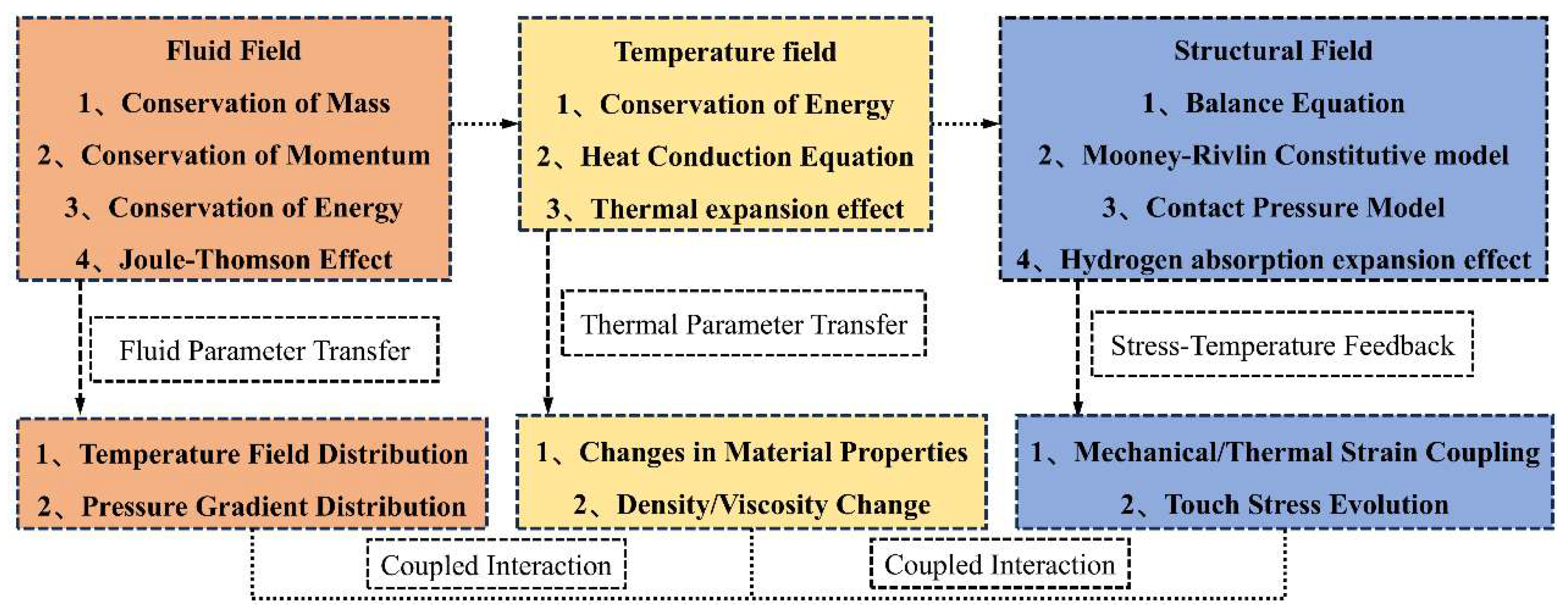
As shown in Figure 2, Considering the hydrogen absorption–thermal coupling expansion effect of the O-ring, a numerical analysis of the dynamic sealing behavior of the O-ring at the cylinder neck is performed using a coupled fluid–thermal–solid approach. The analysis is based on the temperature-rise characteristic curve obtained under linearly decreasing hydrogen filling conditions. The CFD model is developed in accordance with the laws of conservation of energy, momentum, and mass.
Introduction of the Joule–Thomson coefficient μJT:
μ J T = 1 C P T V T P V
In the formula, CP is the specific heat capacity at constant pressure, and V is the molar volume.
The temperature of hydrogen in the hydrogen storage cylinder:
T 1 = Δ T J T + Δ T C + T 0 = Δ P μ J T + T 0 P 2 P 1 γ 1 γ
Energy conservation equation for the filling process of high-pressure Type IV hydrogen storage cylinders:
d c m t d t = a i n A i n T f a T 1 + a f a r u A f a r u T r u T f a + a f a e A f a r u T e T f a + a c e A c e T e T c
In the equation, CH2: specific heat capacity of hydrogen; m: mass of hydrogen filled; ain: heat transfer coefficient between hydrogen and the metal valve seat, units: W/m2/K; Ain: heat transfer area between the valve seat and hydrogen, units: m2; T1: hydrogen temperature, units: K; Tfa: valve seat temperature, units: K; Tru: seal ring temperature, units: K; afa–ru: heat transfer coefficient between the valve seat and the seal ring; Afa–ru: heat transfer area between the valve seat and the seal ring; afa–e: heat transfer coefficient between the valve seat and the external environment, units: W/m2/K; Afa–e: heat transfer area between the valve seat and the external environment, units: m2; Te: external environment temperature, units: K; Cfa: specific heat capacity of the metal valve seat, unit: J/kg/K; mfa is the mass of the metal valve seat, unit: kg; ac–e: heat transfer coefficient between carbon fiber and the environment; and Ac–e: heat transfer area between carbon fiber and the environment.
Calculation formula for thermal strain of sealing rings, Equation (4):
ε t h = α T r u
In the formula, α is the thermal expansion coefficient of PTFE, describing the thermal strain mechanism of the seal ring, where εth represents the thermal expansion strain caused jointly by the temperature change Tru and the thermal expansion coefficient α of the PTFE material.
Strain caused by internal pressure during hydrogen refueling, Equation (5):
ε m e c h = Δ P A E A 0
In the formula, A is the contact area of the seal ring, unit: m2; A0 is the initial cross-sectional area of the seal ring, unit: m2; and E is the elastic modulus of the seal ring, unit: MPa.
The relationship between hydrogen gas swelling and changes in seal ring strain is expressed by Equation (6) [26,27,28,29]:
ε i j H = α H Δ C H δ i j
In the equation, αH is the linear proportional coefficient, ΔcH is the change in hydrogen concentration, and δij is the Kronecker delta.
The total strain of the seal ring is given by Equation (7):
ε 1 = ε i j H + ε m e c h + ε t h
Equation (8) for the relationship between the contact stress of the seal ring and time [32]:
σ P = E ε 1 1 μ 2
The relationship between internal stress and time for sealing rings [33]:
W = C 10 I 1 3 + C 01 I 2 3 + C 20 I 1 3 2
σ = W ε 1
In the equation, W is the strain energy density function, I1 and I2 are the first and second strain tensor invariants, and C10, C01, and C20 are the Mooney–Rivlin coefficients.

2.3. Linear Decreasing Hydrogen Filling Strategy

This study employs a multi-objective optimization framework, targeting the minimization of the weighted sum of filling time and peak hydrogen temperature rise. This approach achieves synergistic optimization of filling efficiency and thermal management, highlighting the strategy’s superior comprehensive performance. Compared to traditional constant-flow refueling, the linear decreasing strategy maintains the same initial flow rate as constant-flow filling during the early refueling phase. Subsequently, it progressively reduces the flow rate to suppress peak temperature rises caused by compression work and the Joule–Thomson effect during the final filling stage. This approach reduces thermal loads on the sealing system and enhances sealing reliability.
To achieve a balance between filling efficiency and thermal management safety, this study employs a weighted summation method to define a multi-objective optimization function:
min J = ω 1 T f T f , r e f + ω 2 max ( T ( t ) ) T 0 T max , r e f T 0
where J represents the objective function, Tf denotes the total filling time, and max(T(t)) indicates the peak temperature during filling, as defined by Equation (2). T0 is the initial temperature of hydrogen gas; Tf, ref, and Tmax are reference values; and ω1 and ω2 are weighting coefficients.
Parameters of the linearly decreasing filling strategy:
X = m ˙ 0 , k T
where m ˙ 0 represents the initial mass flow rate (kg/s) and k represents the flow rate decay rate (kg/s2).
The constraint is expressed using the mass conservation equation. Assuming the initial conditions t = 0, m = m0, the following relationship is obtained:
m t = m 0 + m ˙ 0 + 1 2 k t 2
Introducing the energy conservation equation:
m c v d T d t = m ˙ 0 k t · c p · T i n T h A T T
Under the initial condition T(t = 0) = T0, Equation (14) is solved using the Runge–Kutta method.
Introduction of the gas equation of state:
P t = Z m t / V , T ( t ) · m ( t ) V · R · T t
Hydrogen filling pressure constraints:
P T f = P V
P ( t ) P max , t 0 , t f
Hydrogen filling temperature constraints:
T t T max , t 0 , t f
Hydrogen flow rate constraint:
m ˙ min m ˙ 0 k t m ˙ max , t 0 , t f
where m ˙ 0 ≥ 0, k ≥ 0, and tf ≥ 0.
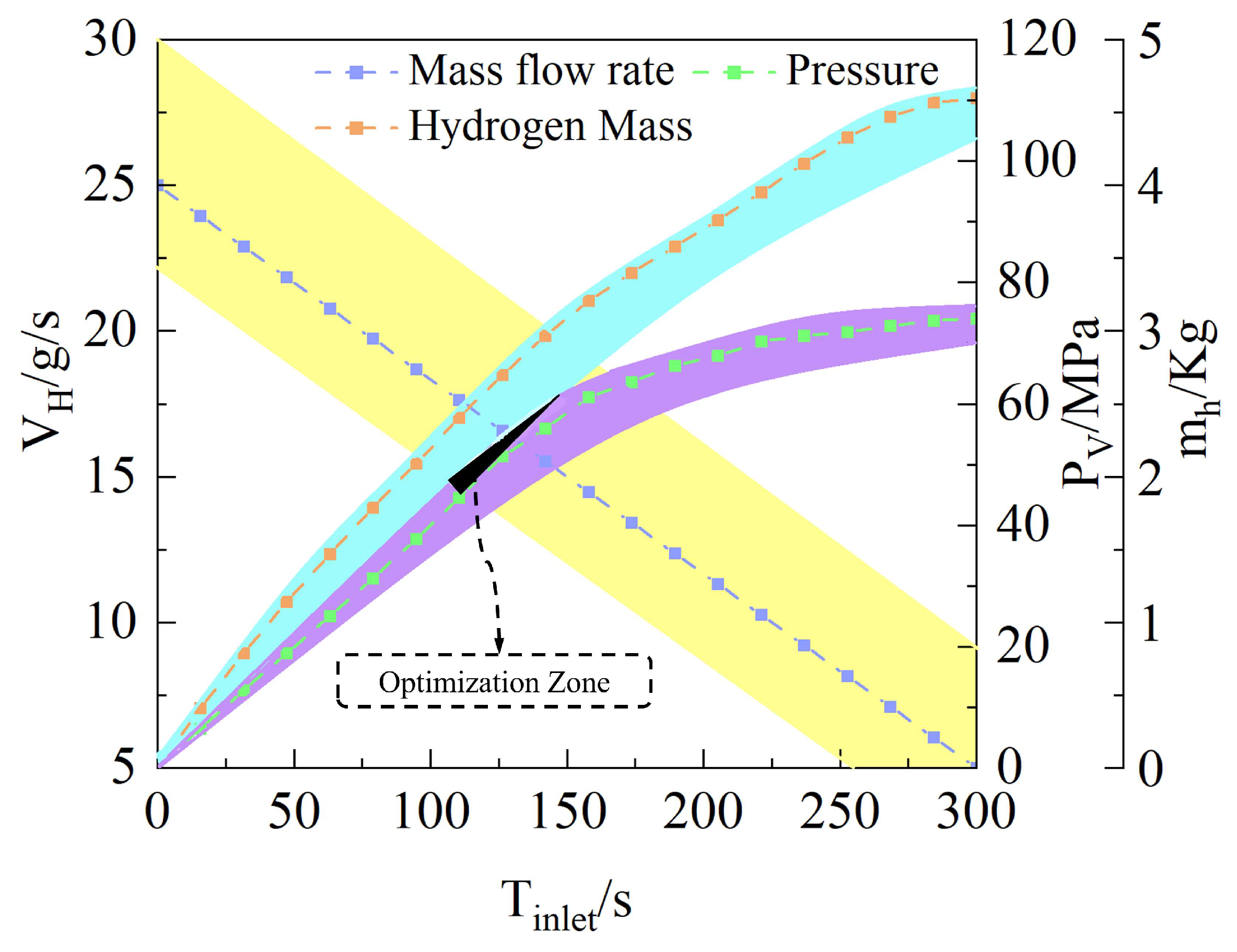
Using the target optimization parameter Tf, the hydrogen filling slope k and the initial mass flow rate m ˙ 0 of the Type IV hydrogen storage cylinder model are optimized, resulting in the outcomes displayed in Table 1 and Figure 3.

3. Numerical Analysis Model

3.1. Analysis Process

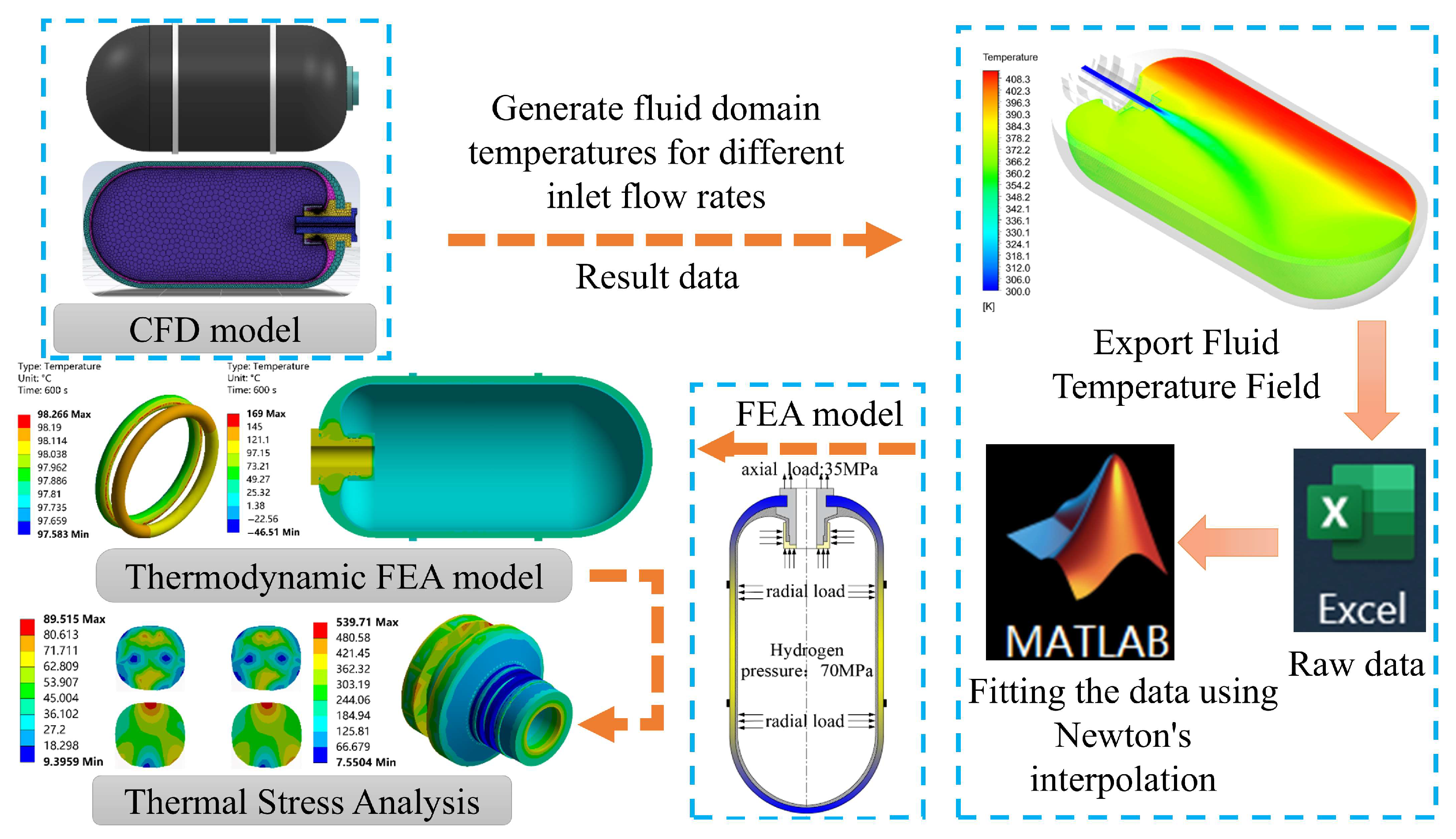
This study employs the fluid–structure–thermal coupling numerical analysis workflow shown in Figure 4 to accurately simulate the dynamic sealing performance of the O-ring during rapid filling. The analysis comprises two core steps: First, computational fluid dynamics (CFD) simulates the transient temperature field within the hydrogen cylinder’s fluid domain under various inlet flow strategies. Second, the CFD-derived fluid temperature data serves as thermal loading to solve the thermo-mechanical response of the O-ring structure. This methodology effectively reveals the performance transfer mechanism from filling strategy to fluid thermodynamic behavior and ultimately to sealing structure performance.

3.2. Model Settings

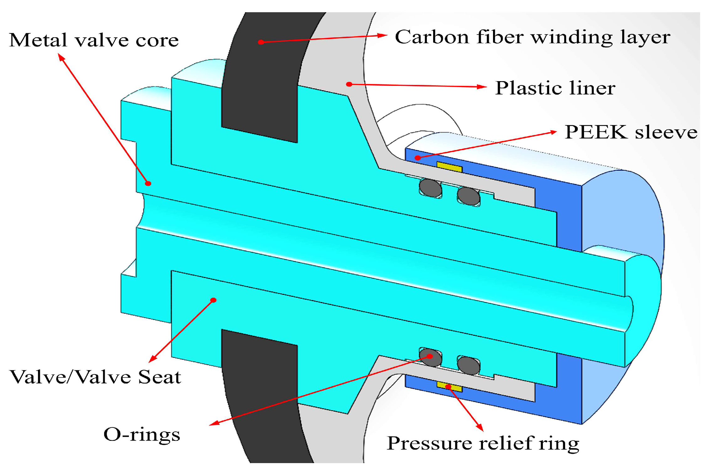
The three-dimensional model of the Type IV hydrogen cylinder established in this study is shown in Figure 5. This model primarily references the experimental research by Li et al. [34] to ensure its validity and comparability. The critical structural components of the hydrogen cylinder include the top metal valve core, carbon fiber winding layer, plastic inner liner, PEEK protective sleeve, valve seat assembly, and the key O-ring seal. The specific design dimensions and material property parameters for each component are listed in Table 2 and Table 3, respectively, providing the geometric and material foundation for subsequent physical field analysis.

3.3. Boundary Conditions and Solution Method

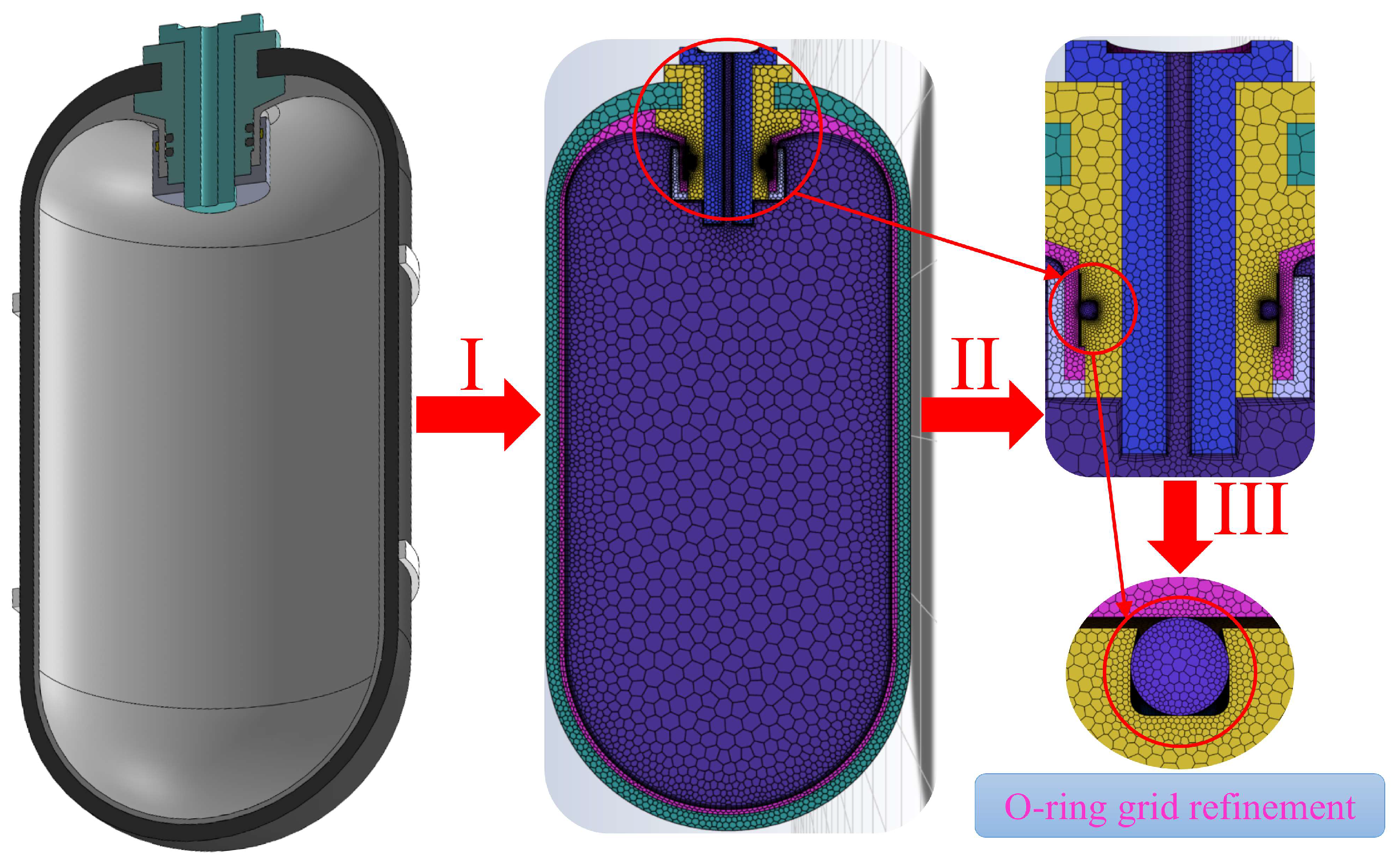
To enhance computational efficiency and accuracy, a region-specific differential meshing scheme was adopted. The Fluent Meshing module was used to generate the computational grid. For fluid–solid coupled boundary layers involving complex heat transfer, unstructured meshes were employed to accommodate irregular geometries. Structured meshes were applied to the fluid regions within the hydrogen cylinder. All regions were meshed using the Poly-Hexcore method. To accurately capture the stress response of the O-ring, local mesh refinement was applied (Figure 6) to ensure the precision of the thermal stress calculation results.
For boundary conditions and material properties, hydrogen is treated as an ideal compressible gas, with a linearly decreasing flow rate employed at the cylinder inlet. Initial model conditions are set as follows: hydrogen initial temperature 298.15 K, environment temperature 295.15 K, and cylinder pressure 2 MPa. For heat exchange between the carbon fiber winding layer, valve/valve seat, and the external environment, convective heat transfer coefficients of 6 W/(m2·K) and 50 W/(m2·K) are set, respectively. Regarding contact settings, friction contact is defined between the O-ring and sealing groove, as well as between the O-ring and plastic liner, with friction coefficients of 0.15 and 0.02, respectively. The penalty function method is employed to find a solution. Specific parameters are detailed in Table 4.

3.4. Verification

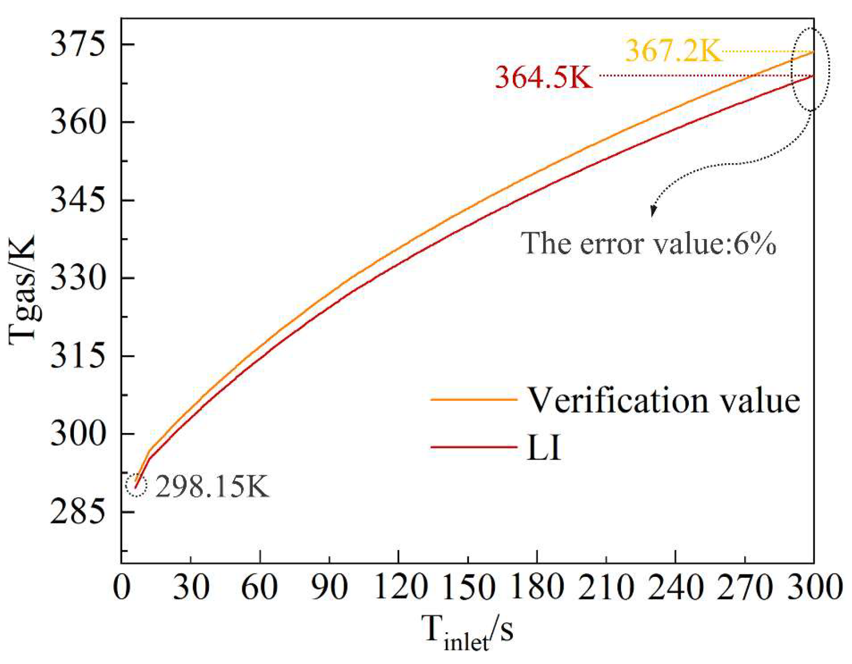
Figure 7 validates the finite element model by comparing experimental hydrogen temperature values during constant-current filling. The simulated temperature curve exhibits similar temperature rise characteristics to experimental data during hydrogen filling, as shown in Figure 7. At critical points such as the end of filling (Tinlet = 300 s), the experimental value was 364.5 K and the simulated value was 367.2 K, with a relative error of only 6%, meeting engineering accuracy requirements. These validation results demonstrate that the fluid–structure–thermal coupled finite element model established in this study accurately reflects the thermodynamic behavior during the filling process, providing a reliable numerical foundation for subsequent seal performance analysis.
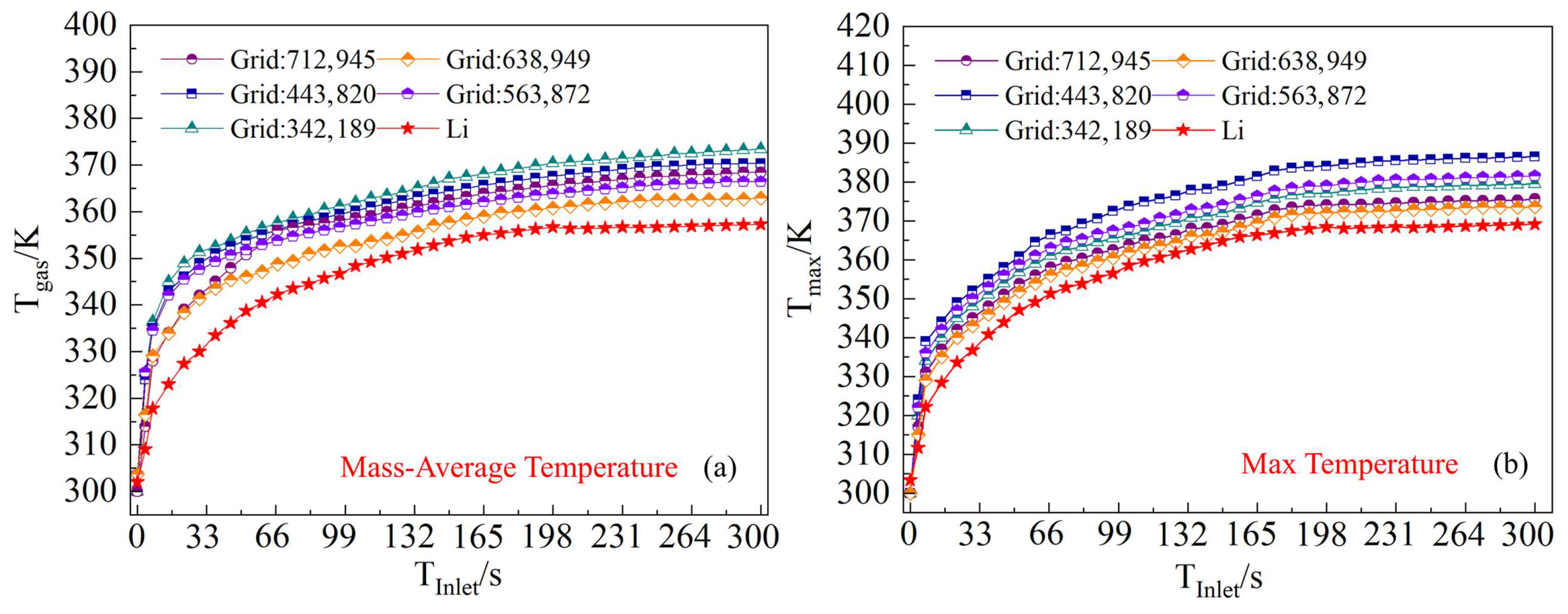
To determine the mesh independence of the computational results, this study simulated hydrogen temperature rise processes for models with mesh counts of 342,189, 443,820, 563,872, 638,949, and 712,945. Figure 8 displays the variation curves of the weighted average temperature and maximum temperature of hydrogen during constant-flow filling across different mesh counts. Analysis indicates that both temperature calculations gradually stabilize as the number of grid cells increases. When the mesh size reached 638,949, further refinement to 712,940 yielded only negligible changes in temperature calculations. Therefore, balancing computational accuracy and efficiency, the model with 638,949 meshes was selected for all subsequent simulations. This mesh density sufficiently ensured the accuracy of computational results.

4. Results Analysis and Discussion

Based on the CFD model of a Type IV hydrogen cylinder, this study employs a fluid–structure–thermal coupling approach to sequentially analyze the dynamic sealing performance of the O-ring during hydrogen filling. The analysis examines factors such as initial flow rate, environment temperature, and O-ring elastic modulus under linearly decreasing filling conditions.

4.1. Comparative Analysis of System-Level Thermodynamic Responses

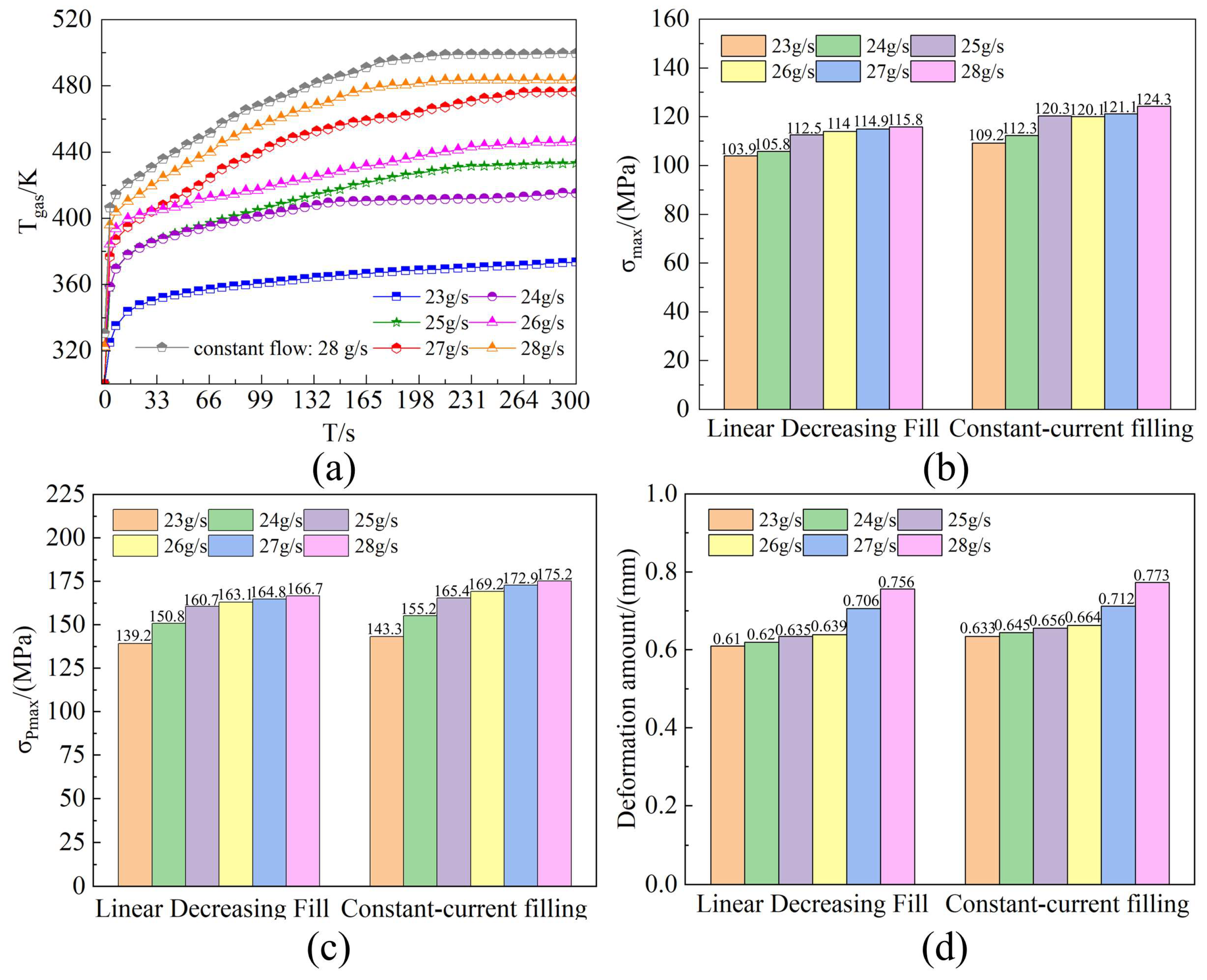
As shown in Figure 9, during linear decreasing filling processes with different initial flow rates, the temperature inside the hydrogen cylinder exhibits a rapid rise trend within the initial 20 s. In the later stages of filling, the temperature change becomes more gradual. Furthermore, the lower the initial filling flow rate, the lower the final temperature upon completion of filling. This phenomenon is attributed to the significantly increased compression work of hydrogen caused by high initial flow rate filling. Throughout the entire filling process, higher initial flow rates result in greater total compression work and higher total heat load, consequently leading to higher final temperatures. Under constant-flow rate filling (28 g/s), the temperature was significantly higher than that observed during linear decreasing flow rate filling. This reflects the differing numerical impacts of initial flow rates on O-ring sealing performance, as shown in Figure 9a–c. the O-ring contact stress, equivalent stress, and deformation under constant-flow filling conditions consistently exceed those under linear decreasing flow conditions. This is highly detrimental to the sealing performance of the O-ring.
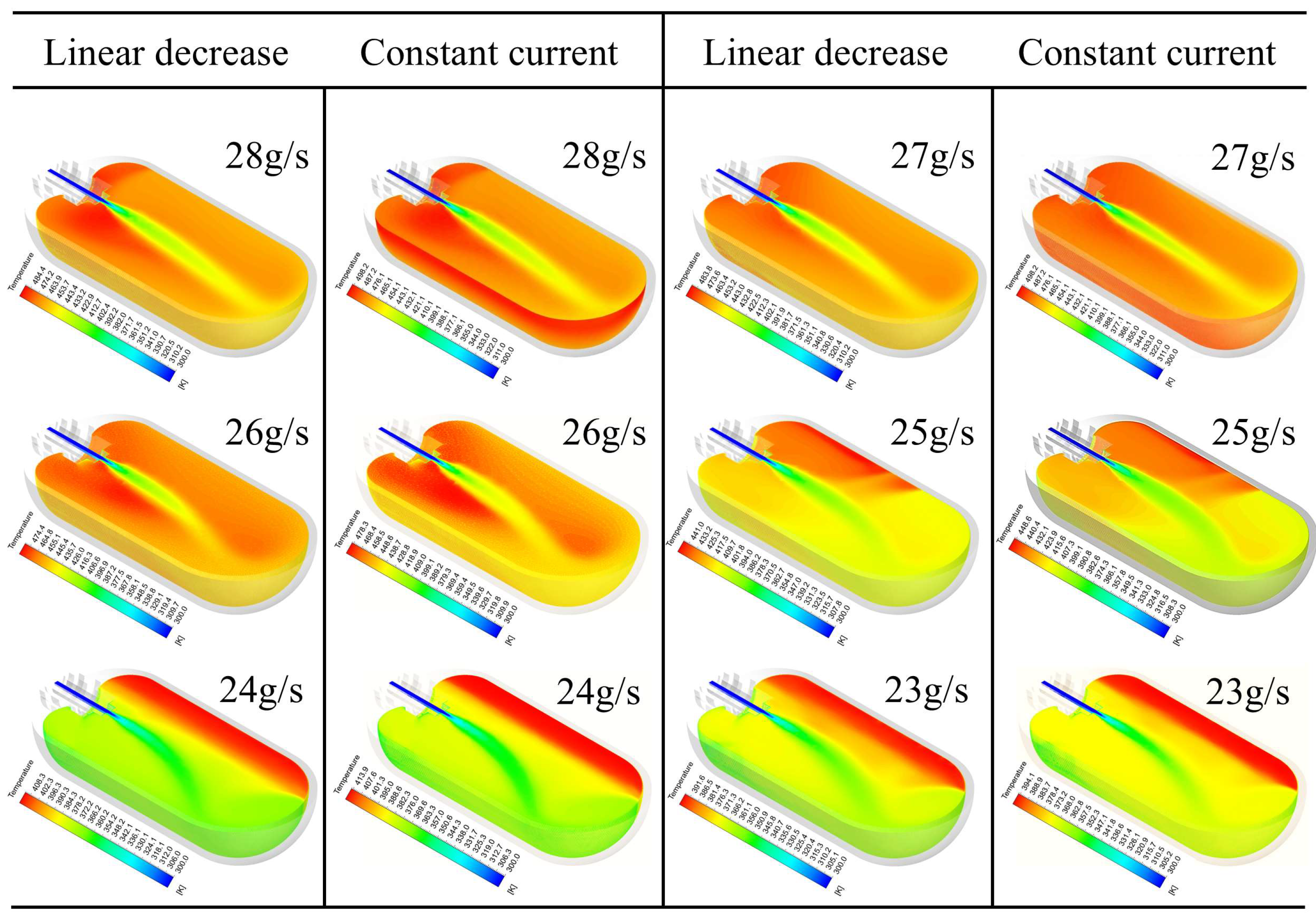
Figure 10 shows the temperature distribution contour map of hydrogen gas inside the cylinder. During the decreasing filling process at an initial flow rate of 28 g/s, the Reynolds number of hydrogen flow is extremely high, with forced convection effects dominating. Turbulent mixing of the fluid rapidly disperses heat within the cylinder, resulting in a high overall temperature average (reaching up to 484.4 K). At this point, the heat transfer mechanism for hydrogen is viscous dissipation within the gas and between the gas and the wall. Conversely, at a lower initial flow rate (23 g/s), the strong convective effect weakens. The density difference of hydrogen plays a significant role in natural convection. Hydrogen near the cooled cylinder wall sinks due to increased density, while high-temperature hydrogen in the central region rises due to decreased density, forming a distinct temperature stratification structure (with a local temperature difference of up to 41.1 K on both sides of the wall). Due to hydrogen’s vortex structure and flow stagnation, heat accumulation occurs in the dome region. Under constant-flow filling, the combined effects of gas compression heat and strong convection intensify the temperature rise within the vessel, resulting in higher peak temperatures. Overall, filling at an initial flow rate of 25 g/s avoids uneven temperature stratification and excessively high overall peak temperatures.

4.2. Environment Temperature Impact Assessment and Contribution Analysis

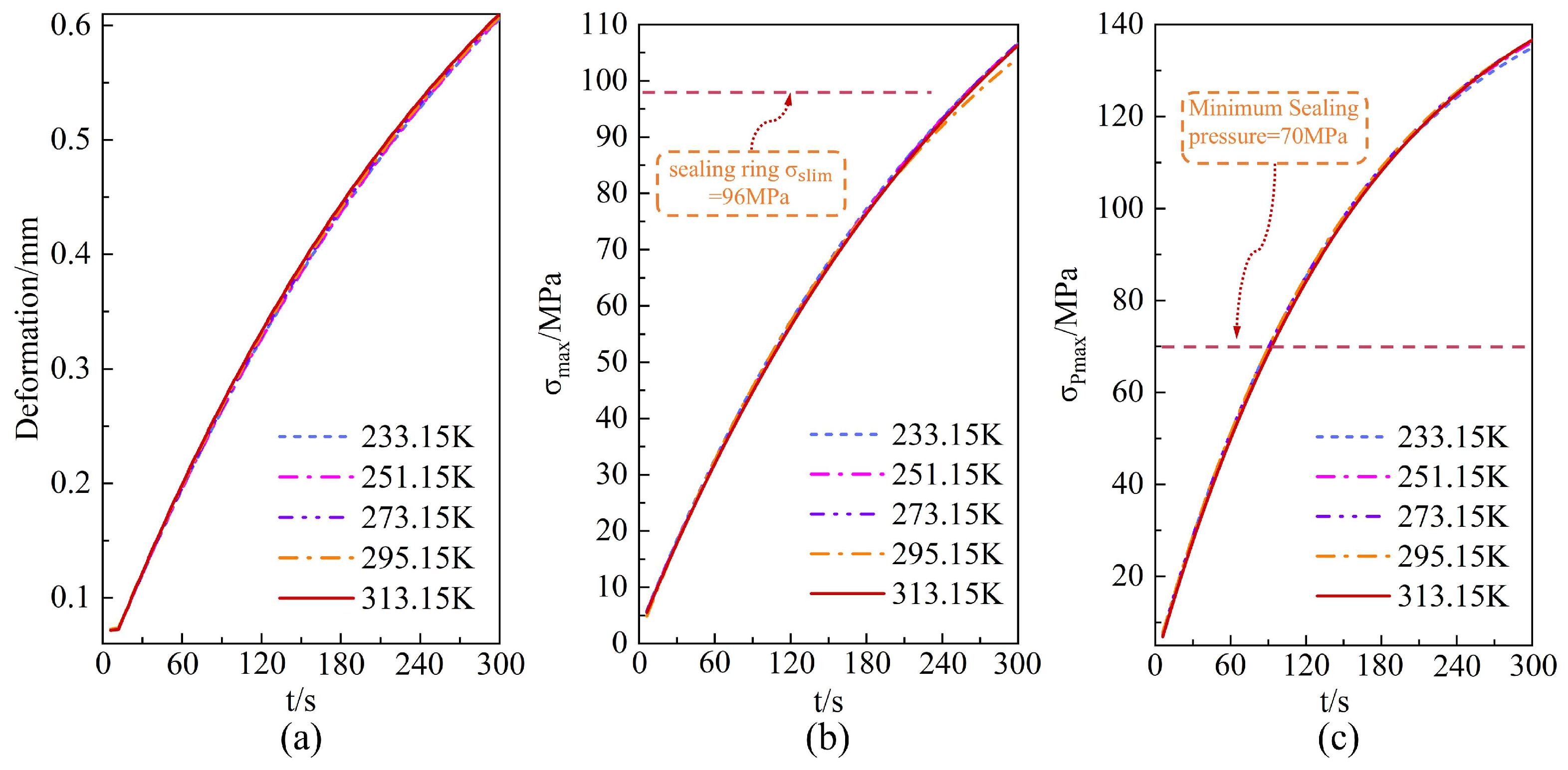
Figure 11 analyzes the dynamic thermal effects on the O-ring as the environment temperature varies from 233.15 K to 313.15 K. The results indicate that although all parameters exhibit nonlinear variations with environment temperature, their magnitude remains limited. The variation rate of the maximum contact stress within the stated temperature range is less than 2%. This variation is far smaller than changes induced by filling pressure fluctuations, with the minimum value remaining above the threshold required to maintain sealing. This occurs because the internal thermal load generated during rapid filling constitutes the primary component of hydrogen temperature rise, while thermal disturbances introduced by environment temperature differences are relatively minor. Consequently, the equivalent temperature gradient around the O-ring changes insignificantly. Therefore, within the specified operating temperature range, environment temperature is not the dominant factor affecting dynamic sealing performance.

4.3. Thermal–Mechanical Coupling Mechanism and the Dominant Role of Sealing Performance

Based on the established thermal environment inside and outside the hydrogen cylinder, the following study investigates the dynamic influence of hydrogen temperature rise effects on O-ring contact stress through thermo-mechanical coupling.
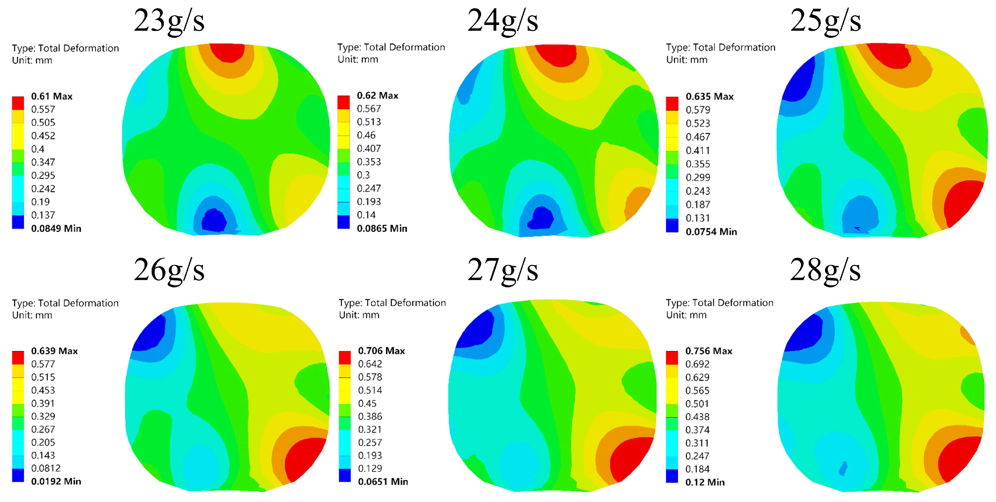
Figure 12 reveals the dynamic impact of hydrogen temperature rise on O-ring deformation under varying initial filling flow rates. As the initial filling flow rate increased from 23 g/s to 28 g/s, the overall temperature and pressure of hydrogen inside the cylinder rose significantly. This triggered thermal expansion effects in the O-ring and subjected it to high-pressure loading, fundamentally causing its maximum deformation to increase from 0.61 mm to 0.756 mm. The deformation distribution exhibits a decreasing trend from the hydrogen contact surface toward the left side of the sealing groove, fundamentally attributable to asymmetric boundary constraints. The right side of the O-ring is directly exposed to high-pressure hydrogen with weaker constraints, while the left side contacts the sealing groove with stronger rigid constraints. This asymmetric constraint forces deformation driven by thermal expansion and internal pressure to evolve primarily toward the side with weaker constraints, forming an uneven deformation field. Under prolonged exposure to high temperature and pressure, the O-ring undergoes transient elastic deformation and may even induce creep, resulting in irreversible lateral displacement at the contact point.
Figure 13 illustrates the dynamic impact of hydrogen temperature rise on O-ring stress under linear decreasing filling conditions with varying initial flow rates. Results indicate that when the initial flow rate increases from 23 g/s to 28 g/s, the maximum equivalent stress on the O-ring rises from 103.9 MPa to 115.8 MPa. The stress distribution exhibits symmetry along the central axis and a distinctive “skull-like” morphology. The physical mechanism underlying this phenomenon is as follows: During filling, the temperature rise of hydrogen gas first induces thermal expansion in the contacting metal liner or valve components. These heated metal parts then exert intense thermo-mechanical squeezing loads on the O-ring constrained between them from both the upper and lower sides. This outward-to-inward, uniformly symmetrical squeezing action causes maximum stress concentration within the O-ring itself rather than at its contact surfaces. This high stress concentration is the key factor inducing material fatigue, readily propagating cracks within the O-ring and ultimately triggering the observed blistering and rupture. Therefore, to ensure sealing reliability, the initial flow rate optimized by the linear reduction strategy should be controlled at a low level, preferably not exceeding 28 g/s.
Figure 14 shows the contact stress distribution of the O-ring under different initial filling flow rates. It reveals the response pattern of the O-ring’s contact stress to the thermal-mechanical load of the entire system. When the initial flow rate increases from 23 g/s to 28 g/s, the hydrogen pressure and temperature inside the cylinder rise, causing the maximum contact stress of the O-ring to increase from 139.2 MPa to 166.7 MPa. This phenomenon arises from two factors: firstly, the hydrogen pressure directly intensifies the radial compression of the O-ring; secondly, the thermal expansion of the O-ring due to temperature rise further increases the compression at the sealing interface. Moreover, the contact stress on the inner circumference of the O-ring (adjacent to the sealing groove) consistently exceeds that on the outer circumference (adjacent to the plastic liner). The fundamental cause lies in the differing stiffness of the materials on both sides of the contact pair. Under prolonged exposure to high temperatures and high contact stresses, the creep phenomenon of PTFE material causes the O-ring to exhibit slow flow and relaxation under constant compression.

4.4. The Micro-Mechanisms of Material Nonlinear Behavior

To gain a deeper understanding of the micro-mechanisms of O-rings under thermo-mechanical coupling, this section focuses on examining the nonlinear changes in O-ring material properties induced by temperature and their regulatory effect on contact stress distribution.
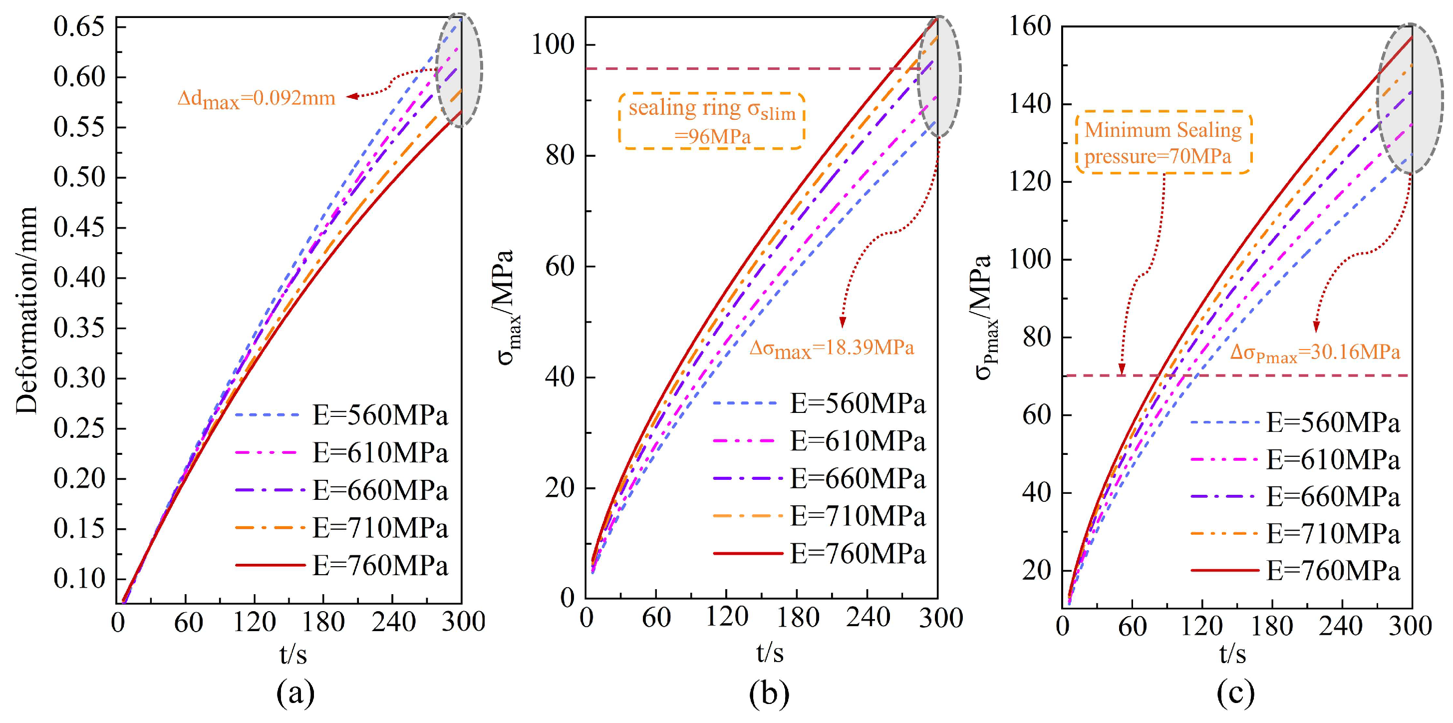
Beyond temperature, the material properties of O-rings—particularly their elastic modulus—exert a decisive influence on sealing reliability. Figure 15 analyzes the dynamic thermal effects of O-rings with varying elastic moduli, tested according to the national standard GB/T 1040.1-2018 [35]. Under optimized filling conditions with an initial flow rate of 25 g/s, the O-ring’s maximum deformation, equivalent stress, and contact stress all exhibit nonlinear increases with filling duration, peaking at 0.658 mm, 104 MPa, and 157.3 MPa, respectively. This occurs because during filling, high-temperature hydrogen gas acts as a heat source, causing thermal expansion of the O-ring while simultaneously subjecting it to high-pressure gas loading. Under this thermo-mechanical coupled load, the elastic modulus—as a measure of a material’s resistance to elastic deformation—directly determines the O-ring’s response characteristics. A higher elastic modulus indicates greater material stiffness, resulting in smaller elastic deformation under identical thermo-mechanical loading. Consequently, as the elastic modulus increases from 560 MPa to 760 MPa, the maximum deformation exhibits a decreasing trend, with a maximum difference of 0.092 mm. Regarding the effects of stress and contact stress: According to Hooke’s law, under similar strain conditions, stress is proportional to elastic modulus. O-rings with higher elastic moduli require greater stress levels to achieve the same deformation. Consequently, as the elastic modulus increases, both the maximum equivalent stress and maximum contact sealing pressure rise significantly, with increments reaching 18.39 MPa and 30.16 MPa, respectively. At an elastic modulus of 760 MPa, the stress approaches the material’s limit, posing a risk of seal failure.

4.5. Multi-Physics Coupling Model Validation and Error Analysis

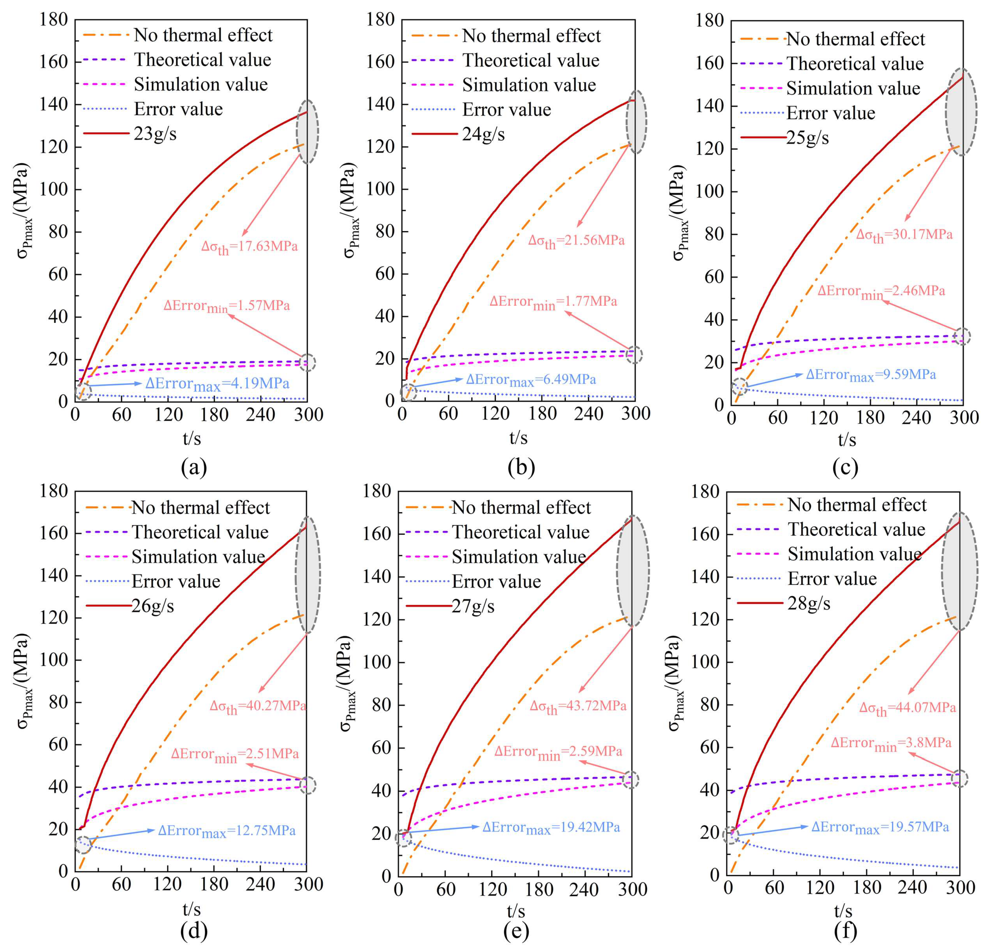
Finally, by systematically comparing the results from three approaches—excluding thermal effects, theoretical predictions, and numerical simulations—the mathematical model developed in this study is validated, and the influence of thermal effects on seal analysis is quantitatively assessed.
In Figure 16a–f, the smaller the initial filling flow rate, the closer the theoretical and experimental values of thermal contact stress on the O-ring due to hydrogen temperature rise become, with reduced error margins. The maximum error between theoretical and experimental thermal contact stress values for the O-ring is 19.57 MPa, while the minimum error is 1.57 MPa. When employing linear decreasing filling at a low initial flow rate, the hydrogen temperature rise within the cylinder becomes slower, resulting in a lower maximum hydrogen temperature. Compared to filling at a higher initial flow rate, low-flow filling exerts a smaller influence on the mechanical properties of the O-ring and causes less variation in material characteristics, thereby reducing errors caused by thermal expansion effects. Therefore, under low-flow rate filling, this mathematical model better predicts the range of thermal contact stress changes in the O-ring.
Figure 14 illustrates the effect of different initial flow rates on O-ring contact stress under a linear decreasing filling strategy, presenting a systematic comparison between theoretical predictions and experimental results. Figure 16a–f present iterative optimization based on the exponential asymptotic function, illustrating the variation patterns of O-ring contact stress under conditions with and without hydrogen–thermal coupling, along with validation results of thermal contact stress evolution over time. Analysis indicates that initial flow rate significantly impacts sealing performance. At higher initial flow rates, more pronounced temperature gradient changes occur within the cylinder during filling, deteriorating the thermal environment at the cylinder neck O-ring. Consequently, the theoretically predicted thermal contact stress increases from 17.63 MPa to 44.07 MPa. This phenomenon occurs because hydrogen permeates into the O-ring material under high-temperature and high-pressure conditions. The hydrogen–thermal coupling expansion causes deformation of the O-ring, manifesting as increased contact stress. In contrast, under lower initial flow rates, theoretical predictions align more closely with simulation results, with a significantly narrowed error range (maximum error 19.57 MPa, minimum error 1.57 MPa). This discrepancy arises because lower initial flow rates effectively suppress the temperature rise of hydrogen within the cylinder. This reduction in peak hydrogen temperature diminishes the thermal load’s impact on the O-ring’s mechanical properties and material characteristics, thereby minimizing prediction deviations. Consequently, the established mathematical model achieves higher prediction accuracy under low initial flow rate linear decrease filling conditions and reliably reflects the range of thermal contact stress variations in the O-ring.

5. Conclusions and Future Work

This study addresses the issue of O-ring sealing failure at the neck of a 70 MPa Type IV hydrogen storage cylinder under fast-filling conditions. A mathematical model of heat transfer for the O-ring under coupled thermal-hydrogen absorption expansion, along with a numerical model incorporating fluid–structure–thermal coupling, was developed. The mechanisms by which hydrogen temperature rise, environment temperature, and O-ring elastic modulus affect the thermal response of the cylinder neck O-ring were systematically revealed. Furthermore, the accuracy of the mathematical model for O-ring thermal contact stress was validated. This work provides critical insights into multi-physics coupled analysis and structural optimization of high-pressure hydrogen cylinder neck seals. The results indicate that:
(1)
The hydrogen filling rate significantly influences hydrogen temperature rise, with the temperature exhibiting nonlinear behavior as the filling rate increases. For each 1 g/s increment in filling rate, the maximum hydrogen temperature rises by approximately 2.062 K on average, while the O-ring at the cylinder neck experiences average increases in deformation, internal stress, and contact stress of 0.00157 mm, 0.128 MPa, and 0.296 MPa, respectively, resulting in a marked reduction in sealing performance. The high-temperature region within the cylinder is concentrated at the dome–valve seat junction, causing pronounced lateral displacement and torsional deformation of the O-ring contact points.
(2)
Increasing the elastic modulus of O-rings enhances structural rigidity and suppresses deformation, but also elevates stress levels, posing a risk of exceeding the material’s yield strength. When environment temperatures fluctuate within the range of 233.15–313.15 K, the impact on the dynamic performance of sealing systems is negligible, with contact stress variations remaining below 1%. This effect is significantly weaker than the temperature rise dominated by hydrogen during the filling process.
(3)
Comparison reveals that the maximum temperature at completion of the linear decreasing filling strategy is approximately 5.3% lower than that of the constant-flow rate strategy, with contact stress fluctuations reduced by 4.6%. For every 0.1 g/s increase in the initial hydrogen filling flow rate, the error between the theoretical and experimental values of the O-ring thermal contact stress increases by 0.3076 MPa. This heat transfer model effectively predicts the evolution of O-ring thermal contact stress during filling at initial flow rates below 25 g/s. The deviation between its predictions and simulation results is only 2.905 MPa. It also effectively controls hydrogen temperature rise, thereby enhancing the sealing performance of the hydrogen storage vessel inlet.
Engineering Implications: Based on the aforementioned research findings, this paper proposes the following engineering implications: When formulating actual filling protocols, it is recommended to set the initial flow rate at 25 g/s as an upper limit reference. To maintain a safety margin, the operational range should be adjusted to 22–24 g/s to balance filling efficiency with temperature rise control. Regarding seal material selection, prioritize materials with an elastic modulus close to 760 MPa to significantly enhance contact stress at the sealing interface. The mathematical model developed in this study serves as an effective predictive tool for evaluating seal reliability under various operating conditions prior to actual filling, facilitating a transition from empirical design to predictive design.
Future Work: This study primarily focuses on sealing performance during single-cycle filling operations, laying a solid foundation for subsequent research. Future work will concentrate on three key areas of in-depth investigation: first, examining the influence of long-term cyclic filling (fatigue effects) on O-ring material aging and sealing performance; second, exploring hydrogen permeation effects under high-pressure hydrogen environments and their long-term mechanisms on material properties; third, establishing a collaborative design window that accounts for different cylinder dimensions and O-ring material parameters to systematically analyze sealing performance boundaries under the coupled effects of key parameters. These studies will advance hydrogen storage vessel sealing systems from transient safety to full-lifecycle reliability design.

Author Contributions

Conceptualization, E.Z. and X.S.; methodology, E.Z.; software, X.S. and W.W.; validation, E.Z., X.S., W.W. and Z.W.; formal analysis, X.S.; investigation, X.S.; resources, E.Z.; data curation, X.S.; writing—original draft preparation, X.S. and W.W.; writing—review and editing, E.Z. and W.W.; project administration, E.Z.; funding acquisition, E.Z. All authors have read and agreed to the published version of the manuscript.

Funding

This research was funded by the National Natural Science Foundation of China, Basic Research Operating Expenses Program for Colleges and Universities, directly under the Inner Mongolia Autonomous Region, grant numbers 52262051 and 2023QNJS069.

Data Availability Statement

The original contributions presented in the study are included in the article. Further inquiries can be directed to the corresponding author.

Conflicts of Interest

We declare that we do not have any commercial or associative interest that represents a conflict of interest in connection with the work submitted.

References

  1. Lee, J.; Kim, J. Balancing hydrogen and nuclear: How nuclear expansion reshapes power-to-gas and hydrogen storage in a carbon neutral energy system. Energy 2025, 336, 138437. [Google Scholar] [CrossRef]
  2. Muhammed, N.S.; Gbadamosi, A.O.; Epelle, E.I.; Abdulrasheed, A.A.; Haq, B.; Patil, S.; Al-Shehri, D.; Kamal, M.S. Hydrogen production, transportation, utilization, and storage: Recent advances towards sustainable. J. Energy Storage 2023, 73, 109207. [Google Scholar] [CrossRef]
  3. Liu, P.F.; Chu, J.K.; Hou, S.J.; Xu, P.; Zheng, J.Y. Numerical simulation and optimal design for composite high-pressure hydrogen storage vessel: A review. Renew. Sustain. Energy Rev. 2012, 16, 1817–1827. [Google Scholar] [CrossRef]
  4. Chen, M.; Hu, Z.; Jia, X.; Yang, Q.; Shen, A.L. Research Progress. on Key Technologies for Type IV Vehicle Hydrogen Storage Cylinders. Press. Vessel. Technol. 2020, 37, 39–50. [Google Scholar] [CrossRef]
  5. Ueda, M.; Hidaka, T.; Ichihara, N.; Yang, H.; Iwase, W.; Matsuda, T.; Morita, N.; Aoki, R.; Yokozeki, T. Voids in type-IV composite pressure vessels manufactured by a dry filament-winding process. Int. J. Press. Vessels Pip. 2024, 208, 105154. [Google Scholar] [CrossRef]
  6. Sebők, B.; Schülke, M.; Réti, F.; Kiss, G. Diffusivity, permeability and solubility of H2, Ar, N2, and CO2 in poly(tetrafluoroethylene) between room temperature and 180 °C. Polym. Test. 2016, 49, 66–72. [Google Scholar] [CrossRef]
  7. Melideo, D.; Desideri, U.; Andreas, J.; Kalisch, T. Zero-Dimensional modeling and optimization of hydrogen refueling for type IV tanks: From validation to large-scale applications. Energy 2025, 332, 137254. [Google Scholar] [CrossRef]
  8. Fragiacomo, P.; Martorelli, M.; Genovese, M. Numerical modeling for analysis and improvement of hydrogen refueling process for heavy-duty vehicles. Appl. Energy 2025, 380, 125092. [Google Scholar] [CrossRef]
  9. Miguel, N.; Cebolla, R.O.; Acosta, B.; Moretto, P.; Harskamp, F.; Bonato, C. Compressed hydrogen tanks for on-board application: Thermal behaviour during cycling. Int. J. Hydrogen Energy 2015, 40, 6449–6458. [Google Scholar] [CrossRef]
  10. Melideo, D.; Baraldi, D.; Galassi, M.C.; Cebolla, R.O.; Iborra, B.A.; Moretto, P. CFD model performance benchmark of fast filling simulations of hydrogen tanks with pre-cooling. Int. J. Hydrogen Energy 2014, 39, 4389–4395. [Google Scholar] [CrossRef]
  11. Dicken, C.J.B.; Mérida, W. Measured effects of filling time and initial mass on the temperature distribution within a hydrogen cylinder during refuelling. J. Power Sources 2007, 165, 324–336. [Google Scholar] [CrossRef]
  12. Li, M.X.; Yang, Q.; Zhang, C.Z.; Huang, S.; Zhang, M.J.; Zhang, G.; Zhao, L.; Jiang, S. Experimental and numerical study of the temperature evolution in hydrogen cylinder under fast-refueling process. Int. J. Heat Mass Transf. 2023, 211, 124220. [Google Scholar] [CrossRef]
  13. Simonovski, I.; Baraldi, D.; Melideo, D.; Acosta-Iborra, B. Thermal simulations of a hydrogen storage tank during fast filling. Int. J. Hydrogen Energy 2015, 40, 12560–12571. [Google Scholar] [CrossRef]
  14. Zhang, E.H.; Zhao, Y.C.; Zhang, J.H.; Wang, W.C.; Yu, W.H. Numerical Analysis of Hydrogen Behavior Inside Hydrogen Storage Cylinders under Rapid Refueling Conditions Based on Different Shapes of Hydrogen Inlet Ports. Energies 2024, 17, 5116. [Google Scholar] [CrossRef]
  15. Wu, Q.G.; Zu, L.; Wang, P.C.; Liu, Z.; Zhang, Q.; Zhang, G.; Chen, S.; Fu, J.; Zhou, L.; Wang, H.; et al. Design and fabrication of carbon-fiber-wound composite pressure vessel with HDPE liner. Int. J. Press. Vessels Pip. 2022, 200, 104851. [Google Scholar] [CrossRef]
  16. Wu, E.Q.; Zhao, Y.; Zhao, B.; Xu, W.P. Fatigue life prediction and verification of high-pressure hydrogen storage vessel. Int. J. Hydrogen Energy 2021, 46, 30412–30422. [Google Scholar] [CrossRef]
  17. Tomioka, J.; Kiguchi, K.; Tamura, Y.; Mitsuishi, H. Influence of temperature on the fatigue strength of compressed-hydrogen tanks for vehicles. Int. J. Hydrogen Energy 2011, 36, 2513–2519. [Google Scholar] [CrossRef]
  18. Ramirez, J.; Halm, D.; Grandidier, J.; Villalong, S.; Nony, F. 700 bar type IV high pressure hydrogen storage vessel burst-Simulation and experimental validation. Int. J. Hydrogen Energy 2015, 40, 13183–13192. [Google Scholar] [CrossRef]
  19. Zhang, Y.K.; Gu, J.F.; Pan, S.; Yang, W.X.; Li, Z.; Ruan, S.; Shen, C. Numerical study on the influence of liner geometry and lay-up sequence on the fatigue life of composite hydrogen storage vessel. Int. J. Press. Vessels Pip. 2023, 205, 104986. [Google Scholar] [CrossRef]
  20. Pépin, J.; Lainé, E.; Grandidier, J.; Benoit, G.; Mellier, D. Replication of liner collapse phenomenon observed in hyperbaric type IV hydrogen storage vessel by explosive decompression experiments. Int. J. Hydrogen Energy 2018, 43, 4671–4680. [Google Scholar] [CrossRef]
  21. Li, Q.; Huang, G.; Qi, L.; Jin, C.; Zhao, Y.; Qiu, S.; Gu, C.; Hua, Z. Thermal-fluid-structure coupling progressive failure analysis for the type III composite cylinder under localized fire. Int. J. Hydrogen Energy 2023, 139, 868–880. [Google Scholar] [CrossRef]
  22. Xu, B.P.; Cheng, C.L.; Wen, J.X. Numerical modelling of transient heat transfer of hydrogen composite cylinders subjected to fire impingement. Int. J. Hydrogen Energy 2019, 44, 11247–11258. [Google Scholar] [CrossRef]
  23. Hupp, N.; Stahl, U.; Kunze, K.; Wilde, P.; Sinske, H.; Hinrichsen, O. Influence of fire intensity, fire impingement area and internal pressure on the fire resistance of composite pressure vessels for the storage of hydrogen in automobile applications. Fire Saf. J. 2019, 104, 1–7. [Google Scholar] [CrossRef]
  24. Zheng, J.; Ou, K.; Bie, H.; Xu, P.; Zhao, Y.; Liu, X.; He, Y. Heat transfer analysis of high-pressure hydrogen storage tanks subjected to localized fire. Int. J. Hydrogen Energy 2012, 37, 13125–13131. [Google Scholar] [CrossRef]
  25. Jaca, R.C.; Godoy, L.A.; Calabró, H.D.; Espinosa, S.N. Thermal post-buckling behavior of oil storage tanks under a nearby fire. Int. J. Press. Vessel. Pip. 2021, 189, 104289. [Google Scholar] [CrossRef]
  26. Zhou, C.; Chen, G.; Liu, P. Finite Element Analysis of Sealing Performance of Rubber D-Ring Seal in High-Pressure Hydrogen Storage Vessel. J. Fail. Anal. Prev. 2018, 18, 846–855. [Google Scholar] [CrossRef]
  27. Zhou, C.; He, M.; Chen, G.; Jiang, S. Numerical study on sealing characteristic of rubber X-ring exposed to high-pressure hydrogen by considering swelling effect. Ind. Lubr. Tribol. 2019, 71, 133–138. [Google Scholar] [CrossRef]
  28. Yamabe, J.; Koga, A.; Nishimura, S. Failure behavior of rubber Oring under cyclic exposure to high-pressure hydrogen gas. Eng. Fail. Anal. 2013, 35, 193–205. [Google Scholar] [CrossRef]
  29. Yamabe, J.; Fujiwara, H.; Nishimura, S. Fracture analysis of rubber sealing material for high pressure hydrogen vessel. J. Environ. Eng. 2011, 6, 53–68. [Google Scholar] [CrossRef]
  30. Fujiwara, H.; Ono, H.; Nishimura, S. Degradation behavior of acrylonitrile butadiene rubber after cyclic high-pressure hydrogen exposure. Int. J. Hydrogen Energy 2015, 40, 2025–2034. [Google Scholar] [CrossRef]
  31. Ma, Y.; Wu, L.; Li, C.; Meng, X.K.; Peng, X.; Jiang, J. Thermal-mechanical-diffusion multi-field coupling behavior of rubber seals in high-pressure hydrogen environment. Int. J. Hydrogen Energy 2025, 112, 333–346. [Google Scholar] [CrossRef]
  32. Wang, B.; Li, X.; Peng, X.; Li, Y.; Li, X.; Chen, Y.; Jin, J. Influence of Nitrile Butadiene Rubber (NBR) Shore Hardness and Polytetrafluoroethylene (PTFE) Elastic Modulus on the Sealing Characteristics of Step Rod Seals. Lubricants 2023, 11, 367. [Google Scholar] [CrossRef]
  33. Li, X.; Wang, B.; Peng, X.; Li, Y.; Li, X.; Chen, Y. Effect of nitrile butadiene rubber hardness on the sealing characteristics of hydraulic O-ring rod seals. J. Zhejiang Univ. Sci. A 2024, 25, 63–78. [Google Scholar] [CrossRef]
  34. Li, J.; Liu, J.; Zhao, B.; Wang, D.; Guo, S.; Song, J.; Li, X. Research on Temperature Rise of Type IV Composite Hydrogen Storage Cylinders in Hydrogen Fast-Filling Process. Energies 2023, 16, 2918. [Google Scholar] [CrossRef]
  35. GB/T 1040.1-2018; Plastics-Determination of Tensile Properties-Part 1. National Technical Committee on Plastics Standardization, Subcommittee on General Methods and Products (SAC/TC 15/SC 4). China Standards Press: Beijing, China, 2018.
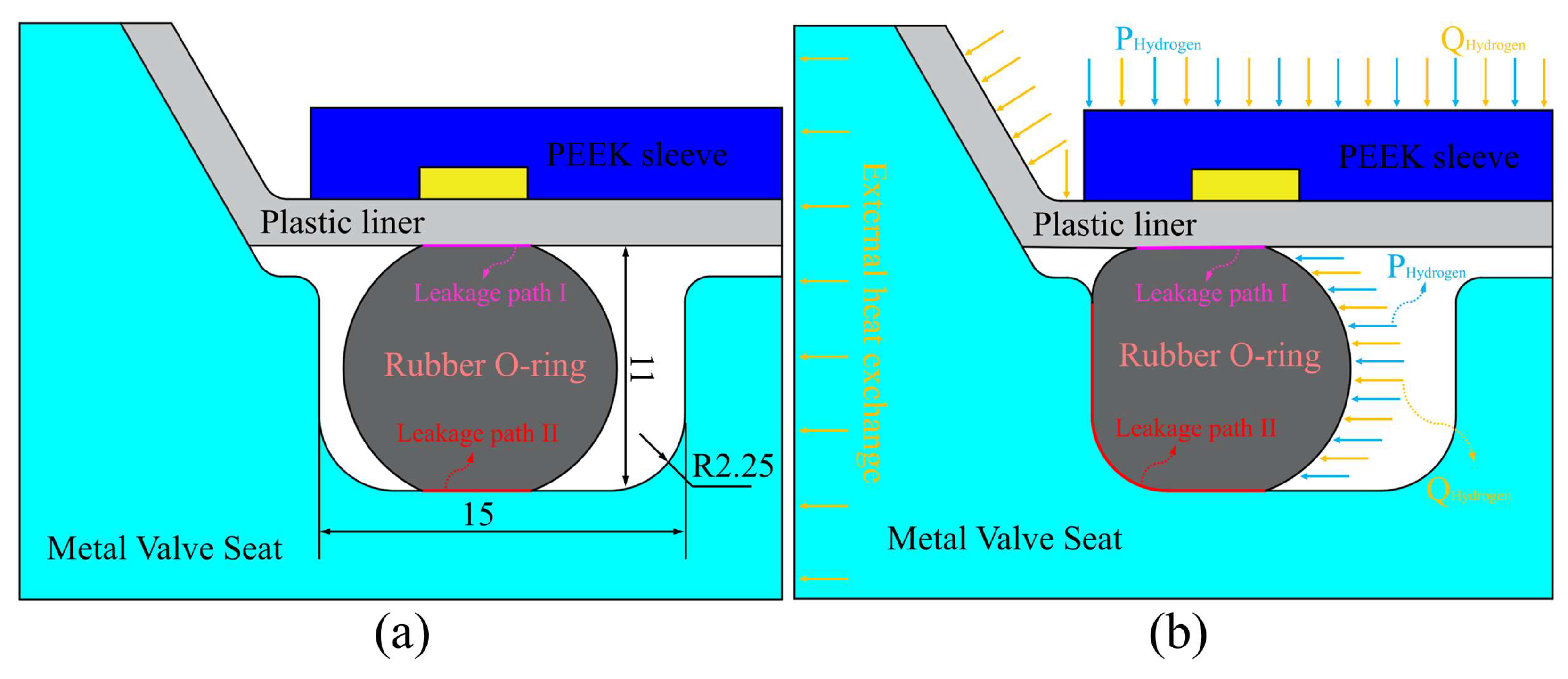
Figure 1. Stress and heat transfer analysis of the O-ring at the cylinder neck with (b) and without (a) hydrogen filling.
Symmetry 17 01921 g001
Figure 2. Analysis approach for fluid–thermal–solid heat transfer model of O-ring.
Symmetry 17 01921 g002
Figure 3. Optimization results of the initial hydrogen filling flow rate.
Symmetry 17 01921 g003
Figure 4. Fluid–structure–thermal coupling numerical analysis process.
Symmetry 17 01921 g004
Figure 5. Three-dimensional model of the Type IV hydrogen storage cylinder.
Symmetry 17 01921 g005
Figure 6. CFD mesh setup.
Symmetry 17 01921 g006
Figure 7. Numerical model validation.
Symmetry 17 01921 g007
Figure 8. Mesh independence verification. (a) Mass-Average Temperature; (b) Max Temperature.
Symmetry 17 01921 g008
Figure 9. Comparison of temperature rise evolution and stress–strain characteristics between linear decreasing filling and constant-flow filling at different flow rates. (a) Temperature Rise of Hydrogen Gas; (b) Equivalent Stress Comparison; (c) Contact Stress Comparison; (d) Deformation Comparison.
Symmetry 17 01921 g009
Figure 10. Hydrogen temperature distribution.
Symmetry 17 01921 g010
Figure 11. Dynamic thermal response of O-rings under varying environment temperatures. (a) Trend in Deformation Variation; (b) Trend of Equivalent Stress Changes; (c) Trend of Contact Stress Variation.
Symmetry 17 01921 g011
Figure 12. Thermal deformation distribution of the O-ring during filling.
Symmetry 17 01921 g012
Figure 13. Thermal stress distribution of the O-ring during filling.
Symmetry 17 01921 g013
Figure 14. Contact stress distribution of the O-ring during filling.
Symmetry 17 01921 g014
Figure 15. Dynamic thermal response of O-rings with varying elastic moduli. (a) Trend in Deformation Variation; (b) Trend of Equivalent Stress Changes; (c) Trend of Contact Stress Variation.
Symmetry 17 01921 g015
Figure 16. Error analysis of contact stress in O-ring. (a) Analysis of Linear Dosing Error at an Initial Flow Rate of 23 g/s; (b) Analysis of Linear Dosing Error at an Initial Flow Rate of 24 g/s; (c) Analysis of Linear Dosing Error at an Initial Flow Rate of 25 g/s (d) Analysis of Linear Dosing Error at an Initial Flow Rate of 26 g/s (e) Analysis of Linear Dosing Error at an Initial Flow Rate of 27 g/s (f) Analysis of Linear Dosing Error at an Initial Flow Rate of 28 g/s.
Symmetry 17 01921 g016
Table 1. Optimization parameter ranges.
Initial mass flow rate, g/s23–30
Slope of the decreasing filling rate−6.10 × 10⁻⁵
Refill time, s300
Final pressure, MPa70.2–76.6
Hydrogen refueling quality, kg4.312–4.632
Table 2. Design parameters for Type IV hydrogen storage cylinders.
ParametersValueReference [34]
Hydrogen storage cylinder capacity V, L80.224
Total length of hydrogen storage cylinder L1, mm891918
Total length of plastic inner cylinder L2, mm803-
Outer diameter of plastic inner cylinder D0, mm384203
Plastic inner cylinder thickness δ1, mm63
Thickness of carbon fiber winding Layer δ2, mm1520
Seal diameter D1, mm9-
Work pressureP0, MPa7070
Table 3. Type IV hydrogen storage cylinder material parameters.
NameO-Ring (PTFE)Valve (6061)Plastic Liner (HDPE)Carbon Fiber
Density (g/cm3)2.22.70.971.8
Modulus of elasticity (MPa)66069,0001080-
Poisson ratio μ0.45320.330.4183-
Coefficient of thermal expansion (K−1)0.000150.0000230.000145-
Specific heat capacity (kg·K)130090022001300
Thermal conductivity (W/(m·K))0.251700.51.5
Table 4. Definition of boundary conditions.
Initial Conditions and Boundary ConditionsValueReference [34]
Initial temperature T0, K298.15298.15
Environment temperature Te, K295.15289
Initial pressure P0, MPa27
Refilling methodLinear decreaseConstant pressure
Convective heat transfer coefficient hout, W/(m2⋅K)66
Disclaimer/Publisher’s Note: The statements, opinions and data contained in all publications are solely those of the individual author(s) and contributor(s) and not of MDPI and/or the editor(s). MDPI and/or the editor(s) disclaim responsibility for any injury to people or property resulting from any ideas, methods, instructions or products referred to in the content.