Article

Obstacle Avoidance Algorithm for Multi-Robot Formation Based on Affine Transformation

1
College of Mechanical Engineering and Mechanics, Xiangtan University, Xiangtan 411105, China
2
College of Electrical and Information Engineering, Hunan Engineering University, Xiangtan 411104, China
*
Author to whom correspondence should be addressed.
Symmetry 2025, 17(11), 1816; https://doi.org/10.3390/sym17111816
Submission received: 1 August 2025 / Revised: 17 October 2025 / Accepted: 24 October 2025 / Published: 28 October 2025
(This article belongs to the Section Computer)

Abstract

Aiming at the problem that obstacle avoidance flexibility and formation integrity are difficult to coexist in multi-robot formation motion, a path-deformation mapping mechanism is proposed, which deeply integrates artificial potential field and affine transformation, and drives formation adaptive adjustment in real time through path information. By using the non-uniform scaling characteristics of the affine transformation, the limitation of traditional conformal transformation is broken through, and the unity of flexibility and integrity is realized. The effectiveness of the algorithm is verified by experiments, which provide a practical solution for cooperative obstacle avoidance of multi-robot systems in complex environments. In order to verify the performance of the algorithm, a numerical simulation is carried out, and an experimental platform composed of seven omnidirectional mobile robots is built for physical verification. The simulation and experimental results show that the formation can complete the obstacle avoidance task in the complex static obstacle environment, and the average formation tracking error is maintained below 0.05 m. Compared with the traditional local obstacle avoidance or formation switching method, this algorithm significantly improves the fluency of the obstacle avoidance process and the integrity of the formation while ensuring a success rate of 100% obstacle avoidance.

1. Introduction

Multi-robot formations have gained widespread attention due to their significant advantages over single robots in handling complex and cumbersome tasks. With the deepening of research on multi-robot formation, obstacle avoidance in formation has gradually gained attention and has become one of the research hotspots [1]. Obstacle avoidance in formation means that multiple robots not only need to be able to maintain formation, but also can avoid obstacles during the execution of a task. The observer-based leader-following formation obstacle avoidance strategy is proposed in [2], which compensates the disturbance to maintain the robustness of formation obstacle avoidance. However, it depends on the preset logic and has limited flexibility under complex obstacles. Reference [3] applies heuristic algorithms to multi-robot systems by combining the advantages of hybrid bio-inspired neural networks with deep Q-networks to enhance the real-time response capabilities of multi-robot systems in sudden obstacle scenarios, laying the underlying perception foundation for cooperative control. Reference [4] applies the interference fluid dynamic system algorithm to formation obstacle avoidance, simulates the natural diffusion characteristics of the fluid after disturbance, generates local obstacle avoidance paths with curvature continuity, and extends the single-machine obstacle avoidance to the path conflict resolution stage of multi-machine collaboration through the dynamic balance mechanism of the velocity field. Literature [5] further deepens the collaborative dimension by proposing a two-tier architecture of sliding mode control and an immune regulation mechanism. The bottom sliding mode surface design ensures the anti-disturbance ability of individual robots, and the upper immune feedback network dynamically allocates formation control weights. This architecture breaks through the traditional rigid formation limitations and achieves the ability to reorganize elastic formations under obstacle impact. Reference [6] for more complex three-dimensional scenarios, a three-dimensional obstacle avoidance control system for unmanned aerial vehicle (UAV) swarms is constructed by using the finite-time consistent formation control algorithm and the improved artificial potential field algorithm, enabling rapid obstacle avoidance of UAV swarms in complex obstacle environments.

1.1. Traditional Formation Control Method

Despite the continuous optimization and improvement of formation obstacle avoidance algorithms, the formation obstacle avoidance methods used are largely similar, mainly the following two methods. The first is local autonomous obstacle avoidance [7,8], where the multi-robot formation does not maintain the formation when encountering an obstacle. Each robot avoids the obstacle independently and then reorganizes the formation after avoiding the obstacle. Reference [9] presents a path planning technique with early warning and obstacle avoidance to ensure that robot formations composed of multiple autonomous underwater vehicles (AUVs) can effectively pass through the obstacle area and then re-form the network framework. The second is formation-switching obstacle avoidance, which can switch to different formation structures in the face of different obstacle situations, enabling it to avoid obstacles. Reference [10] presents a negative fictional switching formation protocol with a directional dynamic topology to avoid obstacles by changing the formation. A velocity-constrained multi-robot switching formation strategy is described in reference [11], where the leading robot uses a geometric obstacle avoidance control method to plan a safe path and controls the following robots to switch to a safe formation by calculating the new expected distance and direction angle to avoid and cross obstacles. Among the two formation obstacle avoidance methods mentioned above, local autonomous obstacle avoidance has higher flexibility, but it takes time to re-form the formation after the formation spreads out. Formation switching obstacle avoidance can maintain the formation during the obstacle avoidance process, but the formation structure needs to be preset in advance. When facing different obstacles, there is no guarantee that the existing formation structure can handle various situations, and it may not be able to change to the best formation due to sudden situations. The flexibility of the obstacle avoidance method is relatively low.

1.2. Affine Formation Control Method

Affine transformation is used in multi-robot formations because it can flexibly adjust the formation. Reference [12] presents the theory of affine formation, which, in the case of an undirected graph network, enables the follower robot to perform an affine transformation by tracking the leader formation through the stress matrix and formation control law. Based on this, reference [13] investigated the control problem of affine formation in directed graphs using the signed Laplacian matrix. With the deepening of the research, affine formation has also been applied to the study of AUVs and unmanned aerial vehicles [14,15], and the tracking accuracy and communication effect in affine formation have been improved through methods such as setting up artificial potential fields between virtual navigators and navigators, using event triggering mechanisms, and adaptive sliding mode control. Reference [16] applied an affine transformation to AUV formation through the AT matrix and virtual navigator and achieved obstacle avoidance in AUV formation through the artificial potential field. At present, the related research mainly focuses on the affine transformation control strategy of the formation, especially the control of the follower. However, in multi-robot formation obstacle avoidance scenarios, the navigator needs to be controlled, and there are fewer control strategies based on the affine transformation.
It is worth noting that the above references [14,15,16] applied an affine transformation to specific platforms such as AUV or UAV, which proved the potential of this theory in different fields. The research object of this paper is the wheeled mobile robots, which aim to solve the problem of obstacle avoidance in the two-dimensional plane. Sun et al. proposed a posture algorithm for mobile robots based on ultrawide band (UWB), which abandons inertial measurement unit (IMU) and other navigation devices that are prone to zero drift, temperature drift, and time-dependent error accumulation. By using UWB tags and base stations, this algorithm can accurately obtain real-time posture information, such as posture angle and speed of mobile robots. Its simulation and experimental results show that the posture data accuracy meets the requirements of most mobile robot applications [17]. At present, the related research mainly focuses on the affine transformation control strategy of the formation, especially the control of the follower. However, in multi-robot formation obstacle avoidance scenarios, the navigator needs to be controlled, and there are fewer control strategies based on the affine transformation. To address the problem that obstacle avoidance flexibility and formation integrity cannot coexist during obstacle avoidance. This paper is not intended to propose a new control architecture, but a creative system integration and improvement of the two mature technologies of artificial potential field and affine transformation. This algorithm uses control laws to achieve follower control and formation of the formation, calculates the obstacle avoidance path using the gravitational field of the target point and the repulsive field of the obstacle, controls the movement of the leader formation along the obstacle avoidance path through the center of the leader formation, and introduces an affine transformation matrix during the obstacle avoidance control process, and performs affine transformation through the leader control formation. The formation is controlled to adjust flexibly to avoid obstacles. To verify the effectiveness of the algorithm, simulations and experiments were conducted using a formation of seven robots, hoping to provide some guidance for the study of obstacle avoidance in multi-robot formations. The main contributions of this paper are twofold. First, we propose a multi-robot formation obstacle avoidance algorithm based on the fusion of the affine transformation and the artificial potential field (APF). The algorithm takes the ‘path-deformation’ mapping as the core, plans the global obstacle avoidance path of the formation centroid through APF, and combines the affine transformation to adjust the formation shape in real time. Second, we adopt the ‘leader–follower’ architecture to achieve obstacle avoidance without dismantling the formation, and solve the problem that the traditional method ‘obstacle avoidance flexibility and formation integrity are difficult to coexist’.
The rest of this article is arranged as follows. In Section 2, an overview of graph theory and formation control laws is presented. In Section 3, the affine transformation and the artificial potential field method are presented, and the formation obstacle avoidance algorithm is implemented by combining them. In Section 4, simulation and experimental verification of the algorithm are presented. The main content of this article is summarized in Section 5.

2. Formation Control Law

2.1. Fundamentals of Graph Theory

Consider a directed graph G = (V,ε), which contains a set of nodes V = {1,2,…,N} and a set of directed edges ε ⊆ V × V. If there is a directed edge, denoted as (j,i) ∈ ε, then node j is called the tail (the starting point of the directed edge), and node i is called the head. Node j is defined as the predecessor of node i, and node i is defined as the successor of node j. Define Ni = {j:(j,i) ∈ ε} as the set of predecessors of node i. In a directed graph, a path is denoted as a sequence of adjacent edges (i,i + 1), (i + 2,i + 3),….
In the formation control law, a directed graph is adopted, and the following properties of the signed Laplacian matrix Ls can be listed.
L s ( j , i ) = ω i j i j , j N i 0 i j , j N i j N i ω i j i = j
Among them, ωji is a real-valued weight (which can be negative or positive) corresponding to the edge (j,i). In general, Ls is a non-symmetric matrix, and it also satisfies Ls1N = 0.

2.2. Control Law

The maintenance of formation is determined by the relative position constraints between robots. In this paper, the definition of formation constraint based on relative displacement is adopted. For a formation composed of N robots, the expected nominal formation consists of a set of vectors g* = [g1*, g2*, …, gN*]. The goal of formation control is to make the actual position pi of all robots converge to a configuration obtained by affine transformation (translation, rotation, scaling) of the desired formation g*, which satisfies the following relationship:
p i = A g i * + b , i 1 , 2 , , N
A is a nonsingular matrix, which represents the linear transformation (rotation, scaling, shearing), and b represents the translation vector. The design goal of control law (4) is to drive the system to achieve and maintain the above constraints.
Consider a network composed of N l intelligent agents. Let p i , i = { 1 , 2 , , N } denote the position of the i-th intelligent agent. Then the positions of the entire formation form a shape, which can be denoted as p = [ p 1 T , p 2 T , p 3 T , , p N T ] T . Based on the leader-following principle, the first Nl robots are set as leaders, and the remaining N f = N N l robots are followers. Then the set of leader nodes is V l = { 1 , 2 , , N l } , and the set of follower nodes is V f = V \ V l . The shape of the Nl leaders is p l = [ p 1 T , p 2 T , p 3 T , , p N l T ] T , and the shape of the Nf followers is p f = [ p N l + 1 T , p N l + 2 T , p N l + 3 T , , p N T ] T . The shape of the entire formation can be rewritten as p = [ p l T , p f T ] T . Information interaction among robots can be carried out through a directed graph G.
Let Ls be the signed Laplacian matrix corresponding to the directed graph G, and it can be partitioned as follows:
L s = 0 N l N l 0 N l N f L f l s L f f s
Among them, Lsff represents the interaction topology among follower robots, and Lsfl represents the interaction topology between follower robots and leader robots. Considering that the follower robot in the formation is a second-order integrator model, the following is established:
p ˙ i = v i v ˙ i = u i
Among them, vi is the velocity information of the follower, and ui is the control input of the follower to be designed. The accelerations of all leaders during the obstacle-avoiding process should be time-varying. Assuming that the absolute acceleration of each robot can be measured, the following distributed control law [13] can be adopted for each follower i ∈ Vf:
p ˙ i = v i v ˙ i = 1 r i d i j N i ω i j [ k p ( p i p j ) + k v ( v i v j ) v ˙ j ]
Among them, di is a designable control parameter that is non-zero, ri = dij∈Niωij and satisfies ri ≠ 0, and kp and kv are normal control gains. According to the above assumptions, the definition of the signed Laplacian matrix, and the block-partitioning of Ls [13], the following can be obtained:
p f ( t ) = L ¯ f f s 1 L ¯ f l s p l ( t )
Among them, the following is established:
L ¯ f f s = L f f s I d L ¯ f l s = L f l s I d
A stable matrix D = diag(di), where i ∈ V, can be set, and it is diagonal and invertible.
D = I d + 1 0 0 D
By processing Ls with matrix D to eliminate non-positive eigenvalues except for d + 1 zero eigenvalues, we can obtain the following:
L ˜ f f s = ( D L f f s ) I d L ˜ f l s = ( D L f l s ) I d
The affine transformation matrix A c (Equation (11)) used in this paper is a general two-dimensional transformation matrix that combines rotation, non-uniform scaling, and translation. One of the core contributions of this paper is its application: instead of performing a preset fixed transformation, a dynamic affine deformation mechanism is proposed. The mechanism takes the path tracking error and obstacle distance as input and calculates and adjusts the rotation angle θ and scaling coefficient in the matrix s c ( t ) in real time to drive the formation to produce adaptive deformation. This strategy of real-time formation change driven by environmental feedback is a key innovation to achieve flexible obstacle avoidance.
The position tracking error δpf of the followers, i.e., the formation error [13], can be defined as follows:
δ p f ( t ) = p f ( t ) p f ( t ) = p f ( t ) + L ˜ f f s 1 L ˜ f l s p l ( t )
Formulas (3)–(10) describe how the follower tracks the leader formation for the affine transformation. Based on this, the formation control problem for multiple leaders is studied in this paper, and the affine transformation of the leader formation is implemented in the following text. Then, through the above-mentioned follower control law, the formation as a whole is made to achieve an affine transformation.

3. Obstacle Avoidance Formation Control

3.1. Affine Transformation

It is assumed that the followers in the formation satisfy this affine transformation condition. In this paper, a matrix Ac is defined for affine transformation coordinate calculation, which is composed of a rotation matrix Arot and a scaling matrix Asc. This matrix is mainly used to realize the rotation and scaling of the leader formation within the formation.
A c ( t ) = A r o t ( t ) A s c ( t )
Among them, the following is established:
A r o t ( t ) = cos ( θ ( t ) ) sin ( θ ( t ) ) sin ( θ ( t ) ) cos ( θ ( t ) )
In the rotation matrix Arot, θ(t) ∈ [0, 2π) is the formation rotation angle.
A s c ( t ) = s c ( t ) 0 0 s c ( t )
In the scaling matrix Asc, sc(t) is the formation contraction coefficient. Then, the affine transformation calculation formula for the leader formation with the coordinate point s as the center can be expressed as follows:
p a t ( t ) = s + ( A c ( t ) × ( p l s ) )
Among them, pat represents the position coordinates of the leader formation after the affine transformation, Ac(t) is the affine transformation matrix, and pl is the position coordinates of the leader formation before the affine transformation. Suppose multiple leaders form a formation, and the formation after the affine transformation via Formula (14) is as shown in Figure 1.
Compared with conformal transformations such as Helmert transformation or similarity transformation, the affine transformation selected in this paper includes non-uniform scaling and shearing, allowing adaptive deformation of formations. This feature is an important improvement for obstacle avoidance scenarios: in the face of asymmetric narrow channels, conformal transformation can only enlarge or shrink the formation as a whole, while affine transformation can flexibly pass through by scaling in a specific direction, thus maintaining the integrity of the formation while providing higher obstacle avoidance ability and environmental adaptability. The comparison of the three transformations is shown in the following Table 1:

3.2. Artificial Potential Field Method

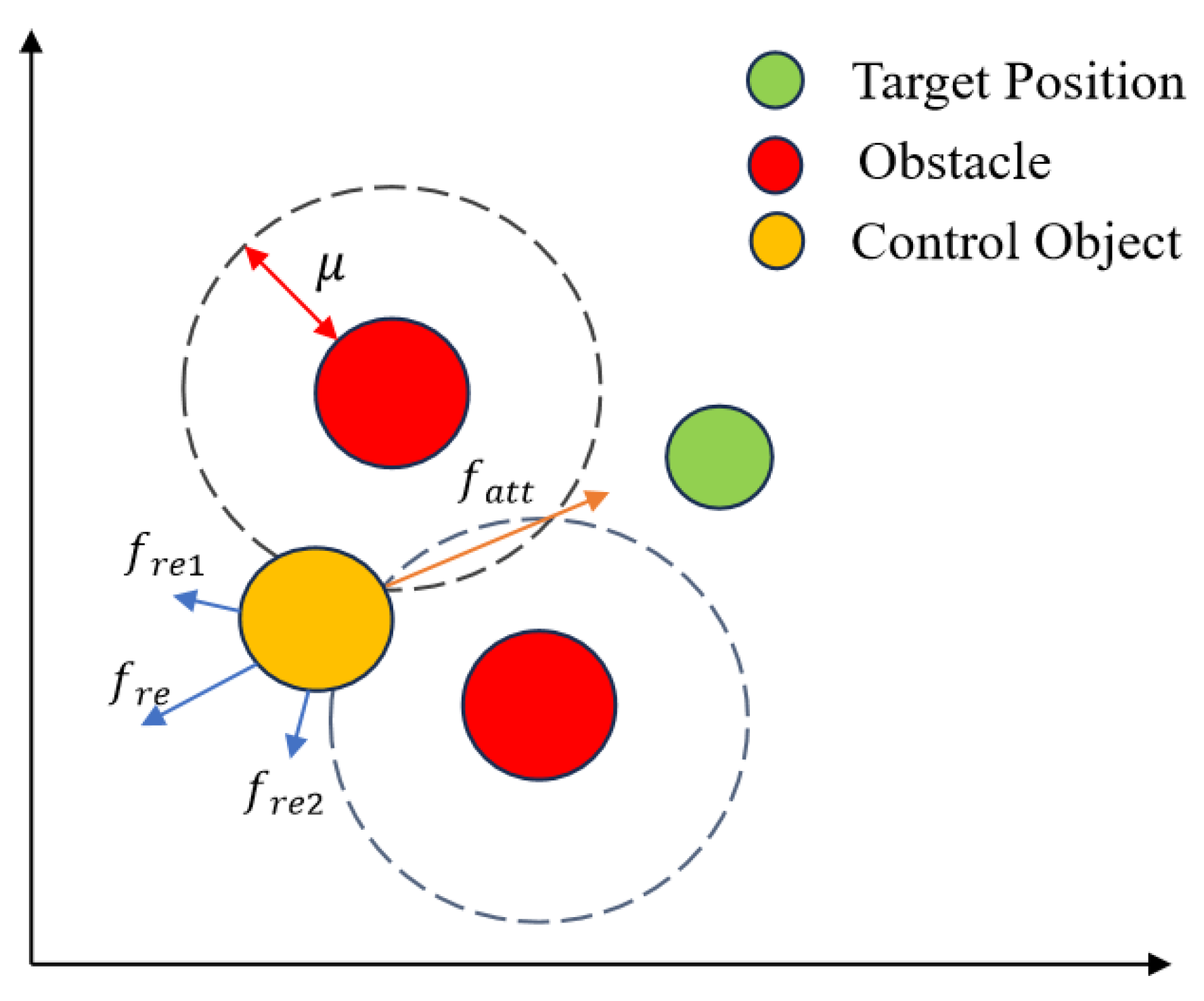
Using a single robot as the controlled object plo, by setting a repulsive force field for a known obstacle and a gravitational field for the target position through the artificial potential field method, the movement direction of the controlled object and the obstacle avoidance path to avoid the obstacle and move to the target point can be calculated, as shown in Figure 2.
The gravitational potential field function is as follows:
U a t t ( p l o ( t ) ) = 1 2 k a t t p l o ( t ) q o bs 2
Among them, katt is the gain constant of the attractive field, qobs is the position of the target point, and |plo(t) − qobs| is the distance between the controlled object and the target point at the current moment.
Differentiating the above Equation gives the gravitational function of the target point.
f a t t ( p l o ( t ) ) = U a t t ( p l o ( t ) ) = k a t t q o b s p l o ( t )
The repulsive potential field function is as follows:
U r e ( p l o ( t ) ) = 1 2 k a b s ( 1 p l o ( t ) q o b s 1 μ ) 2 0 p l o ( t ) q o b s μ p l o ( t ) q o b s > μ
where kabs is the repulsive field gain constant. μ is the maximum range of influence of the obstacle; beyond the range of influence, the controlled object is not affected by its repulsive force. |plo(t) − qgoal| is the distance between the controlled object and the edge of the obstacle at the current moment.
Taking the derivative of the above Equation gives the repulsive function of the obstacle.
f r e ( p l o ( t ) ) = U r e ( p l o ( t ) ) = k a b s ( 1 p l o ( t ) q g o a l 1 μ ) p l o ( t ) q g o a l p l o ( t ) q g o a l 3 0 p l o ( t ) q g o a l μ p l o ( t ) q g o a l > μ
From the above, it is known that the total potential field function is as follows:
f ( p l o ( t ) ) = f a t t ( p l o ( t ) ) + f r e ( p l o ( t ) )
Define the set PTAPE to store all coordinate data of the moving path of the controlled object. At the initial moment, PTAPE contains the initial position (Fx1,Fy1) of the controlled object plo.
For each time step Δt, the formula for updating the position of the controlled object is as follows:
p l o ( t + Δ t ) = p l o ( t ) + Δ f p l o ( t ) f p l o ( t )
Updating the path PTAPE data, the following is established:
P T A P E = P T A P E { p l o ( t + Δ t ) }
Therefore, when the position of the static obstacle is known, the path data PTAPE of the controlled object moving towards the target position and being able to avoid the obstacle can be obtained, consisting of multiple discrete coordinate data points of the controlled object plo from the initial position to the target position, which can be expressed as follows:
P T A P E = { ( F x 1 , F y 1 ) , ( F x 2 , F y 2 ) , , ( F x n , F y n ) }
The obstacle avoidance path of the controlled object in a static obstacle environment can be calculated through Formulas (12)–(22). It provides a path basis for the obstacle avoidance control strategy described later, allowing the navigators to move along this path, thereby achieving the goal of the robot formation moving towards the target position and avoiding the obstacle.
In this paper, the application of the classical artificial potential field method is improved. Traditional APF is usually used to control the movement of a single robot, and this paper innovatively applies it to plan the path for the centroid of the entire formation. This transformation is crucial: the safe path of the centroid provides global guidance for the movement of the entire formation, and then, through the affine transformation mechanism described in Section 3.3, this single path information is calculated as the deformation control command of the entire formation. In this way, the force conflicts and shocks that may be caused by the direct application of APF to each robot are avoided, and the integrity and synergy of formation behavior are ensured. This strategy of ‘planning for the centroid and deformation for the whole is one of the core innovations of integrating APF and affine transformation in this paper.

3.3. Obstacle Avoidance Formation Control

The data of the obstacle avoidance path PTAPE for the controlled object is calculated by the artificial potential field method, and there are usually multiple navigators in the formation. Assuming all the navigators as a whole are the controlled objects, it is possible to control the movement of the formation and perform obstacle avoidance by controlling the movement of this whole according to the path data PTAPE. Combining the characteristics of an affine transformation during the avoidance process makes obstacle avoidance more flexible.
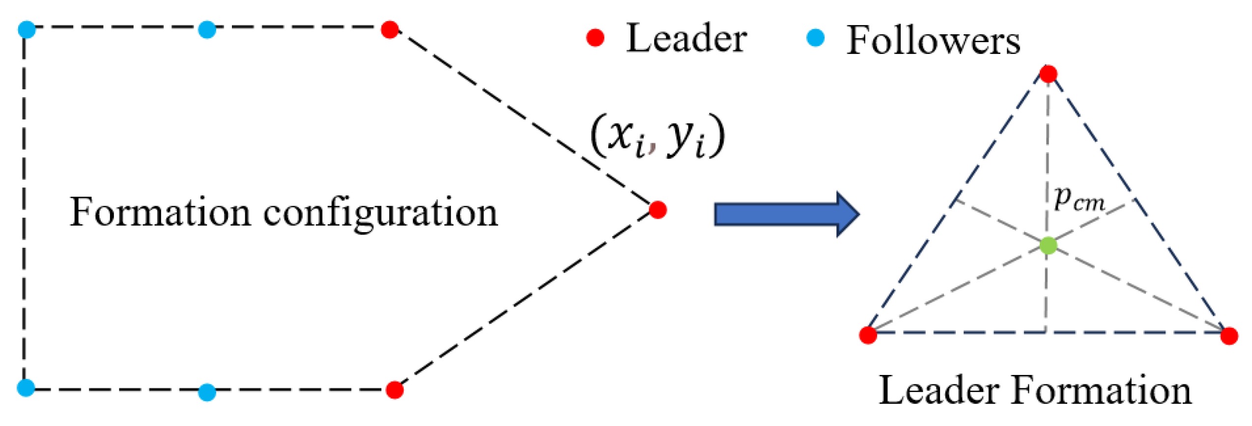
As shown in Figure 3, the leader formation is a two-dimensional graph formed by multiple leaders as vertices. To make it move according to the path data of PTAPE, the centroid coordinates pcm = (xcm,ycm) of this graph can be calculated, where xcm and ycm are the x and y coordinate data of the centroid pcm of the two-dimensional graph formed by the leader formation at the current moment. By moving the centroid along the path given by PTAPE, the target position pltar of the leaders when moving along this path can be obtained.
The formula for calculating the polygonal centroid is as follows:
x c m = i = 1 n x i n y c m = i = 1 n y i n
where xi and yi are the coordinates of the i-th vertex of the polygon, that is, the coordinates of the i-th leader.
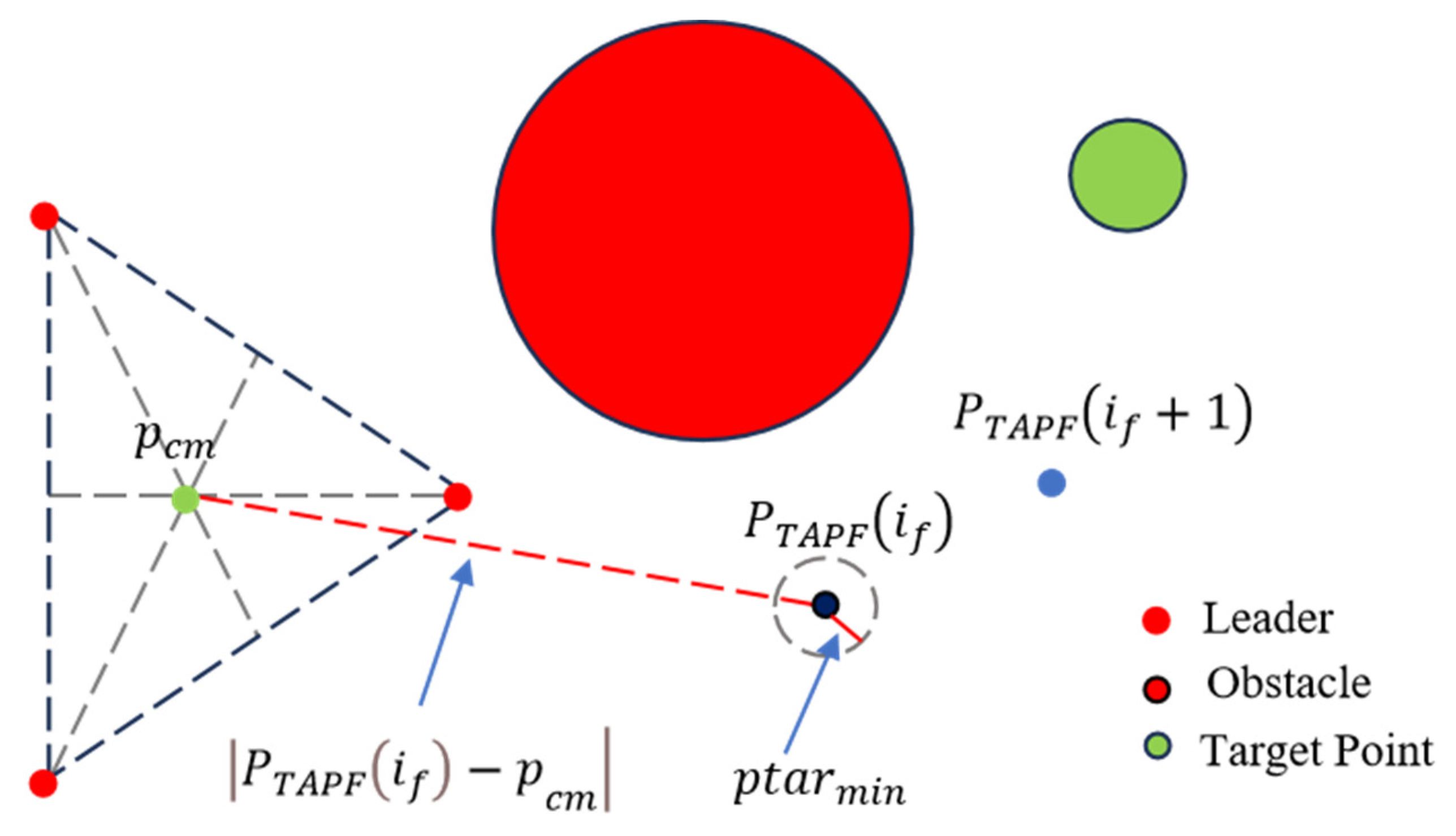
Define if to represent the index of path data, and initialize if = 1. When the distance error between the if-th path data of PTAPE(if) and the centroid pcm is less than the minimum distance error ptarmin, it is regarded as reaching the coordinate indicated by this index. Then, the index if is incremented, such that its controller can use the next path data for calculation, as shown in Figure 4.
i f = i f + 1 P T A P E ( i f ) p c m p t a r min 0 t = 0
An obstacle avoidance path, PTAPE, is a path composed of multiple discrete coordinate points. When the center of the shape moves along the obstacle avoidance path, it moves in sequence according to the coordinate points on the path according to the index if.
Therefore, the target positions that each navigator should reach at different times are calculated in real time based on the target coordinate points corresponding to the content and the index if. The coordinates of the navigators need to be replaced during the calculation process, and the calculated PTAPE(if) target position is the position after the affine transformation centered on the target point.
The real-time target position pltar = [pl1T,pl2T,pl3T, …,plNlT]T of the navigator is denoted as, and the calculation formula is as follows:
p t a r = P T A P E ( i f ) p c m p l t a r = ( ( p l + p t a r P T A P E ( i f ) ) × A c ( t ) ) + P T A P E ( i f )
An affine transformation matrix Ac(t) was introduced when calculating the target position, allowing the formation to perform affine transformations based on obstacle distance and path information during obstacle avoidance, as shown in Figure 5.
The calculation process of the rotation angle θ(t) and the scaling coefficient sc(t) in Ac(t) is as follows. Define the error vector.
p c m s = ( x c m s , y c m s )
This represents the distance vector between the centroid and the coordinates of the current target point in the path.
p c m s = p c m P T A P E ( i f ) 0
The xcms and ycms can also be expressed as follows:
x c m s = x c m F x i f y c m s = y c m F y i f
Fxif and Fyif are the x-coordinate and y-coordinate data in the if-th path data of the PTAPE path. The rotation angle θ(t) in Ac(t) can be calculated from xcms and ycms, and θ is 0 when t = 0.
θ i = arctan ( y c m s x c m s ) + f ( x c m s , y c m s ) x c m s 0 π 2 x c m s = 0 y c m s > 0 π 2 x c m s = 0 y c m s < 0
It θi is the corresponding angle at which the center of the nominal formation moves to the target value at the current moment. θall is the rotation angle at which the current formation is equivalent to the nominal formation. The rotation of the formation can be obtained by subtracting the rotated angle from the corresponding angle θ(t).
θ ( t ) = θ i θ a l l
θ a l l = k = 0 t 1 θ ( k )
The f(x,y) is the function used to adjust the quadrant when handling the angle transformation, returning the appropriate values based on the signs of x and y to adjust the angle to the correct quadrant. It is defined as follows.
f ( x , y ) = 0 π x > 0 x < 0
The scaling coefficient sc(t) of Ac(t) is calculated from the distance between the nearest obstacle and the centroid coordinate pcm. The initial value of sc(t) at t = 0 is 1, and the calculation formula for t > 0 is as follows.
s c ( t ) = ( 1 k d max p c m q o b s min k d max ) 1 s c a l l p c m q o b s min < k d max 1 s c a l l p c m q o b s min k d max
s c a l l = k = 0 t 1 s c ( k )
In the formula, |pcm − qobsmin| is the distance between the centroid and the nearest obstacle at the current moment. scall is the scaling coefficient of the current formation relative to the nominal formation. After taking its reciprocal, the corresponding value of the scaling coefficient sc(t) when restoring the nominal formation can be obtained. Kdmax is the threshold of the minimum distance from the centroid in the leader formation to the obstacle. If the distance is greater than this threshold, it can be regarded as an obstacle that does not affect the movement of the leader formation. Then, the formation is restored to the nominal formation; otherwise, it means that the obstacle is too close and may collide with the leader formation. In this case, it is necessary to scale the formation through an affine transformation based on the nominal formation to avoid the obstacle.
The selection of key parameters, such as repulsion gain coefficient k o b s and distance threshold k d max is very important. k o b s should be large enough to ensure effective obstacle avoidance repulsion, but too large will lead to path oscillation; k d max determines the trigger time of obstacle avoidance behavior. Its value is usually set to be slightly larger than the maximum contour radius after the affine transformation of the formation (as shown in Figure 3, the distance from the leader’s centroid to the farthest robot) to ensure the safety of the entire formation. The parameter values in this paper are mainly determined by simulation experiments after weighing obstacle avoidance safety and path smoothness.
The navigator robot is described using the first-order integrator model.
p ˙ j ( t ) = v j ( t )
where vj(t) is the control input of the j-th navigator, and control laws can be applied to each navigator:
p ˙ j ( t ) = k j ( p j p l j )
Among them, the proportional gain kj is a constant used to adjust the intensity of the control law; pj is the current position of the j-th navigator; plj is the target position of the j-th navigator.
It is known from the target position calculation Formula (25) that the navigator target position is calculated based on the obstacle avoidance path and the affine transformation matrix. By controlling the navigator’s approach to the target position through the control law, the navigator can move to avoid obstacles, and in the process, the followers will be affected by the navigator’s formation, ultimately achieving the affine transformation of the formation as a whole to avoid obstacles.

4. Results and Discussion

4.1. Simulation Validation

This section mainly uses MATLAB (R2023b) simulation to verify the effectiveness of the proposed obstacle avoidance algorithm. Here, it is assumed that the obstacles are static and that the information exchange between the robots is directed. Consider a formation system consisting of seven robots, where 1–3 are the navigator robots and 4–7 are the follower robots. The information exchange between the robots is shown in Figure 6 [13]:
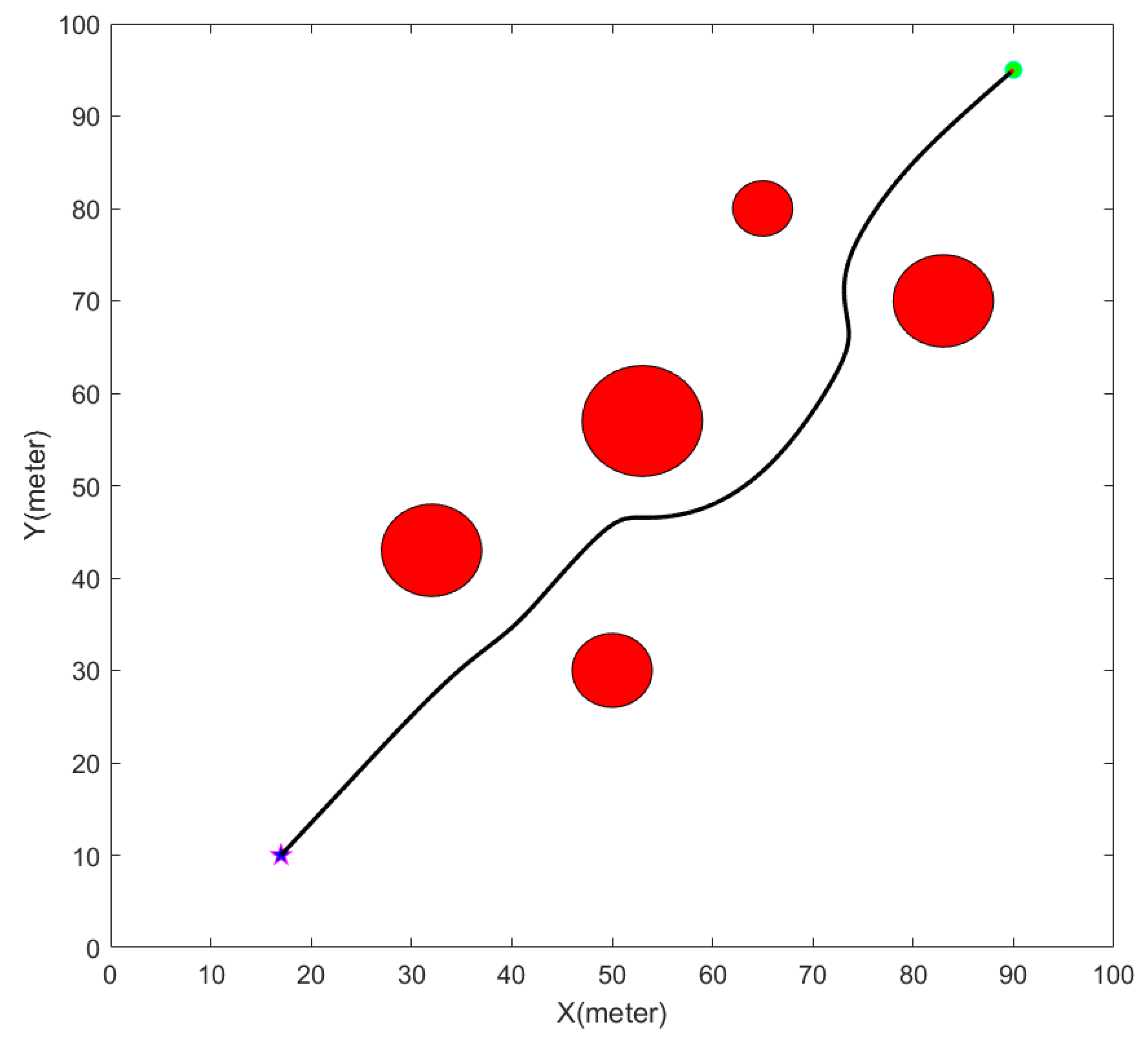
First, set katt the gravitational gain coefficient of the gravitational function in Formula (15) to 5, the repulsive gain kobs coefficient of the repulsive function in Formula (17) to 100, the Δt time step to 0.5, and give the target position coordinates as (90,95), the starting coordinates as (17,10), and randomly generate multiple static obstacles.
The obstacle avoidance path is shown in Figure 7. The red circle in the figure represents the obstacle; the green dot represents the target position; the blue star represents the starting position, and the black path represents the obstacle avoidance path calculated based on the current obstacle position and under the effect of the repulsive force field of the obstacle and the gravitational field of the target position. It can be seen from the figure that the obstacle avoidance path avoided the obstacle well, kept a certain distance from the obstacle, and finally reached the target position, providing the path basis for the subsequent formation operation experiment.
Set kv to 3 in the follower control law, set kp to 0.5, and set kj, the gain parameter, to 5 in the navigator control law. In the calculation of the navigator target position, the minimum distance error in Equation (24), ptarmin, is set to 0.05, and in Equation (33), kdmax is set to 12.68. This parameter is approximately the distance between the center pcm of the navigator formation and the farthest robot in the formation. Using this distance as the threshold for the closest distance between the formation and the obstacle can prevent a collision between a robot in the formation and the obstacle. Thus, a simulation of the movement of a multi-robot formation along the obstacle avoidance path through an affine transformation was calculated.
The setting of the safety threshold k d max fully considers the conservatism of obstacle avoidance. On the basis that the geometric size of the formation is the distance from the centroid to the farthest robot, the physical radius of the robot and the obstacle, and the maximum expected error of the positioning system are added as the safety margin. The composite design ensures that a reliable safety gap between the formation and the obstacles can be maintained even in the worst case, effectively preventing collisions.
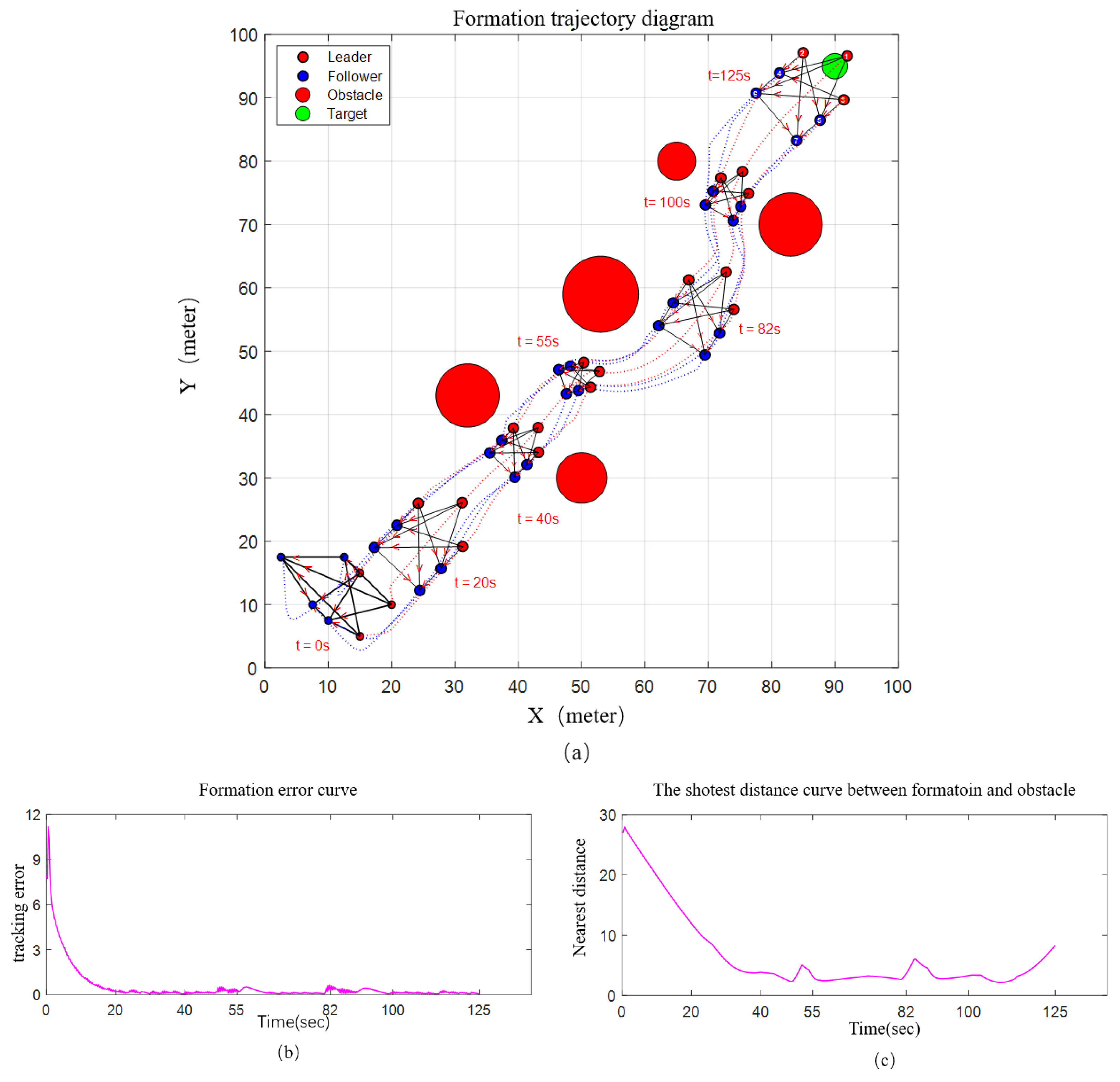
Figure 8 shows the simulation results of the obstacle avoidance experiment and the related data curve. The formation trajectory is shown in Figure 8a. During the operation, the multi-robot formation is initially in a fragmented state and gradually forms the nominal formation as it moves from 0 s to 20 s. As can be seen from the formation trajectory in Figure 8a, the formation was too close to the obstacle at 40 s, 55 s, and 100 s, and was reduced by an affine transformation to better avoid the obstacle at 82 s and 125 s. When they were far from the obstacle, they would return to the nominal formation. Figure 8b shows the position tracking error of the followers during the movement of the formation. The error calculation Formula (10) shows the deviation of the real-time position of all follower robots from the theoretical position in the formation, which also reflects the integrity of the formation during operation. The curve of the distance between the formation and the nearest obstacle during the formation operation is shown in Figure 8c. It can be seen from the figure that during the approach to the obstacle, the formation adjusts the formation through an affine transformation, such that the robot closest to the obstacle in the formation keeps a certain distance from the nearest obstacle, indicating that no collision has occurred. Ultimately, the multi-robot formation can move along the obstacle avoidance path and adjust the formation size through an affine transformation to avoid the obstacle and reach the target position.
Figure 9 shows the transformation curve of the relevant parameters of the formation affine transformation during formation operation. The formation rotation angle curve is shown in Figure 9a. During the movement of the formation, multiple direction adjustments were made. The curves in the figure show the rotation angles of the robot formation relative to the nominal formation at each moment. When the values increase, the formation rotates counterclockwise; when they decrease, the formation rotates clockwise. In Figure 9a, the angle of the navigator formation is 0 at 0 s, the formation rotates counterclockwise by about 45 after the formation starts, the formation rotates significantly at 55 s, and also rotates significantly in the interval between 82 s and 100 s. The trajectory direction transformation of the formation in Figure 8a is basically consistent with the numerical transformation trend of the rotation angle in Figure 9a, indicating that rotation control of the formation can be achieved by adjusting the rotation angle in the affine transformation matrix. The curve of formation scaling ratio changes is shown in Figure 9b, and the formation is adjusted through an affine transformation in order to avoid obstacles during movement. scall is the scaling ratio of the formation of the robot formation at each moment relative to the nominal formation, and the closest distance qobsmin of the obstacle in Figure 9b is roughly consistent with the change in the scaling ratio scall. At the time when qobsmin < kdmax, the number of scaling ratios, scall, would change according to Equation (33) and cause the formation to shrink. At the time when qobsmin ≥ kdmax, the scaling ratio scall will be restored to 100%, restoring the formation to the nominal formation. As can be seen from Figure 9b, the formation remains unchanged between 0 s and 20 s, at the nominal formation size (100%), and is reduced around 40 s, 55 s, and 100 s in order to avoid obstacles. After avoiding the obstacle, the formation gradually reverts; for example, from 55 s to 82 s, the formation gradually reverts to the nominal formation. Then, from 82 s to 100 s, the formation was reduced and restored to avoid the obstacle. The affine transformation of the formation during the operation in Figure 8a is basically consistent with the curve change trend in Figure 9b. Therefore, by controlling the parameter transformation in the affine transformation matrix, the formation’s affine transformation during operation can effectively avoid obstacles and reach the target position.
The simulation results show that the obstacle avoidance algorithm proposed in this paper enables the multi-robot formation to flexibly adjust the formation size through affine transformation when encountering static obstacles during movement to avoid static obstacles without disassembling or disrupting the formation during the obstacle avoidance process, thus maintaining the integrity of the formation.

4.2. Experimental Verification

To verify the effectiveness of the proposed formation obstacle-avoidance algorithm, this paper uses seven omnidirectional robots and a positioning system. The single robot model is shown in Figure 10a. The upper computer and communication network are used to form a multi-robot formation system to conduct formation obstacle-avoidance experiments. As shown in Figure 10b.
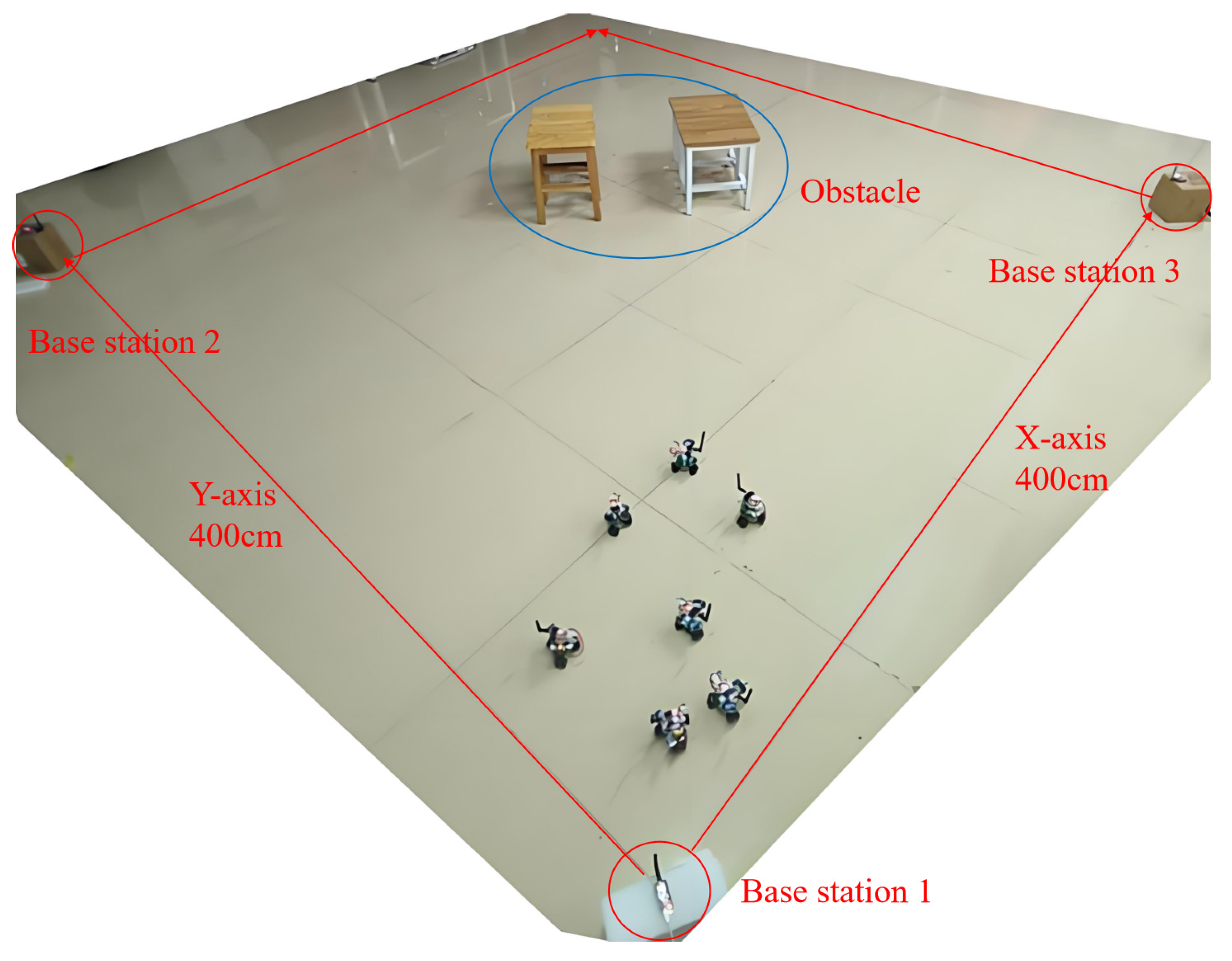
Set up a 400 cm × 400 cm formula editor square moving experimental area to conduct static obstacle avoidance experiments. The experimental area is shown in Figure 11, where three UWB base stations powered by power banks are placed in sequence at the vertex positions of the edge of the area. The nominal formation of the robot formation refers to the nominal formation in the simulation. Due to the influence of the actual robot size, the nominal formation in the simulation is proportionally enlarged by 4 times to obtain the nominal formation in the experiment, and the corresponding Laplacian matrix, communication topology, etc., are obtained.
First, place the No. 1, 2, and 3 navigator robots in sequence near positions (95,70), (65,75), and (100,50) in the experimental area to form the navigator formation in the nominal formation and then randomly place the followers in sequence at a certain position in the area behind the navigator to obtain the initial formation of the multi-robot formation. Then, set up two obstacles in the field to form an obstacle area, and test whether the multi-robot formation can calculate the obstacle avoidance path and move along the obstacle avoidance path when the position information of the obstacle is known, and adjust the formation size in real time through an affine transformation based on the distance data of the obstacle to pass through the obstacle area.
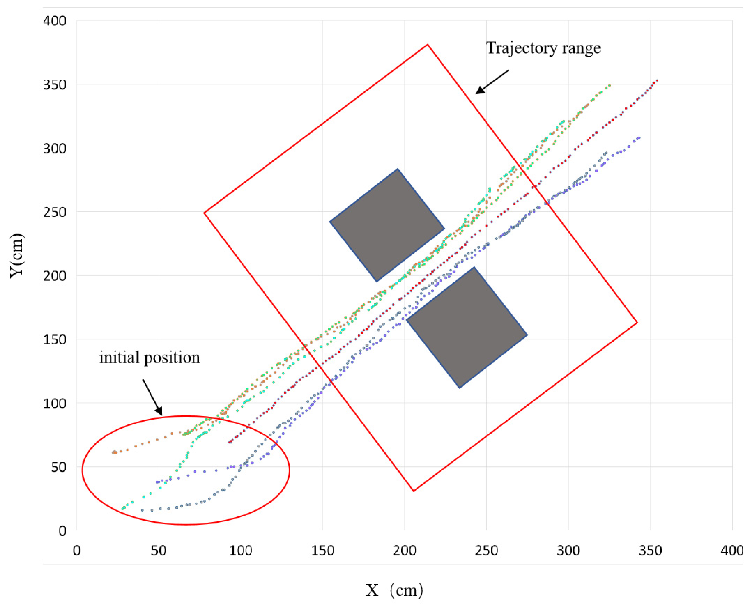
The movement trajectory of the robot on the upper computer interface is shown in Figure 12. Among them, the position coordinates of different robots are represented by different colors, and multiple coordinate points form the movement trajectories of each robot. As can be seen from the trajectory marked by the red circle in the figure, after starting, since the positions of the followers are randomly shuffled, the position tracking will be carried out quickly to form the formation. From the trajectory range marked in the red box in the figure, it can be seen that after the formation is formed, as the movement progresses, the formation will gradually shrink as it approaches the obstacle, and after passing through the obstacle area, the formation will gradually return to the nominal formation size, and finally, the formation will avoid the static obstacle through formation affine transformation.
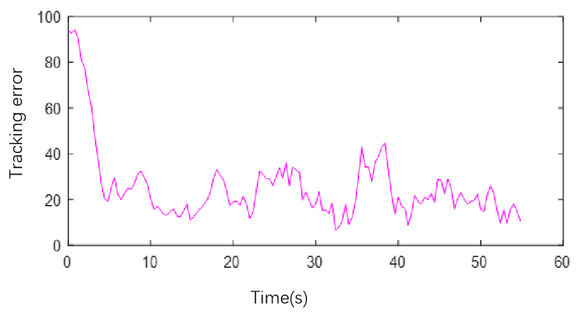
The upper computer saves the position data of each robot during the experiment and calculates the follower’s real-time tracking error using the Formula (5). The tracking error variation curve during the experiment is shown in Figure 13. At the beginning of the operation, the tracking error was large because the positions of the followers were disrupted. As the followers continuously corrected their positions, the tracking error decreased. During the formation affine transformation process, the tracking error of the formation also fluctuated, but all decreased as the formation stabilized, indicating that the multi-robot formation was able to maintain the formation better during movement.
It should be noted that the follower control law (Equation (5)) in Section 2.2 is designed based on the second-order integrator model (Equation (4)), and its theoretical control input is acceleration. However, the bottom layer of the omnidirectional mobile robot used in this experiment is controlled by the built-in PID controller. To solve the difference between theory and practice, we use a hierarchical control architecture of ‘host computer numerical calculation acceleration + integral generation speed command + underlying PID tracking’. We effectively approximate the theoretical second-order integrator model and acceleration control hypothesis on the actual speed control platform.

5. Conclusions

In this paper, a formation obstacle avoidance algorithm combining an affine transformation and the artificial potential field method (APF) is proposed. The unique contribution of the algorithm is to use the non-uniform scaling ability of the affine transformation to enable the formation to actively carry out adaptive deformation to pass through complex obstacles. While strictly maintaining the mathematical integrity of the formation (affine framework), it achieves far more obstacle avoidance flexibility than the conformal transformation method. Simulation and experimental results quantitatively demonstrate the effectiveness of the algorithm: the average formation tracking error was maintained below 0.05 m, confirming the high formation-keeping integrity. During obstacle avoidance, the minimum distance between the formation and the nearest obstacle was always greater than the safety threshold, ensuring a 100% collision-free success rate. Furthermore, the affine transformation parameters were adapted dynamically to the environment: the scaling coefficient varied within a range of 60% to 100%, and the rotation angle was adjusted flexibly within ±45°, validating the algorithm’s capability for real-time deformation while preserving the formation structure.
However, there are still some limitations in this study. Firstly, the algorithm is mainly aimed at the known static obstacle environment, and the ability to deal with dynamic obstacles has not been verified. Secondly, the performance of the algorithm depends on stable communication links and accurate environmental awareness, and its robustness may need to be further enhanced in scenarios where communication is limited or perception noise is large. In addition, the relevant parameters in the artificial potential field are currently mainly selected through experimental experience, and adaptive optimization has not yet been achieved.
Based on the above limitations, the future research work can be carried out from the following aspects: First, the algorithm is extended to the dynamic environment, and the theory of speed obstacle method is integrated to avoid moving obstacles; secondly, the robust control strategy under communication delay and perceived uncertainty is studied to improve the anti-interference ability of the system. The third is to explore the parameter adaptive mechanism based on machine learning (such as reinforcement learning) to enhance the generalization performance of the algorithm in different scenarios. Finally, the algorithm in the two-dimensional plane can be extended to the three-dimensional space obstacle avoidance task of the UAV cluster. This method can be further extended to the dynamic obstacle scene. The core expansion idea is to replace the static distance information with the dynamic risk assessment based on perception and prediction. By driving affine transformation parameters to respond to dynamic threats, the existing ‘path-deformation’ mapping architecture can be directly reused, such that the formation has forward-looking obstacle avoidance capabilities.

Author Contributions

Conceptualization, Q.Z. and Y.S.; methodology, Q.Z.; software, Z.Z. and Y.S.; validation, Q.Z., Y.S., Y.Z., J.S., Z.W. and W.D.; formal analysis, Q.Z. and J.S.; investigation, Q.Z. and Z.W.; resources, Q.Z. and W.D.; data curation, Q.Z. and Z.Z.; writing—original draft preparation, Q.Z. and Y.S.; writing—review and editing, Q.Z., Y.S., Y.Z., J.S., Z.Z., Z.W. and W.D.; visualization, Q.Z. and Y.S.; supervision, Y.Z.; project administration, Y.Z.; funding acquisition, Y.Z. All authors have read and agreed to the published version of the manuscript.

Funding

This work is supported by the National Natural Science Foundation of China (52175254), Hunan Provincial Innovation Foundation for Postgraduate (CX20230550, CX20240614).

Data Availability Statement

The data presented in this study are available on request from the corresponding author. Comprehensive Table of Simulation Parameters can be found in Appendix A.

Conflicts of Interest

The authors declare no conflicts of interest.

Appendix A. Comprehensive Table of Simulation Parameters

The following table systematically sorts out the key parameters in the artificial potential field (APF) path planning and multi-robot formation control simulation, covering the four core modules of basic setting, path management, control law adjustment, and affine transformation.
Parameter CategoryParameter NameSymbolFunction Description
Artificial Potential Field (APF) Basic ParametersAttractive Field Gain CoefficientkattAdjusts the gravitational pull of the target point on the formation centroid, ensuring stable movement toward the target without path deviation from insufficient attraction.
Repulsive Field Gain CoefficientkobsRegulates the repulsive force of obstacles on the formation centroid—sufficient to avoid collisions when approaching obstacles, while preventing path oscillation from excessive repulsion.
Time StepΔtBalances simulation efficiency and trajectory smoothness. Too large a step causes discrete trajectories; too small causes increases in computational cost.
Maximum Obstacle Influence RangeμDefines the effective range of obstacle repulsion. Beyond this, obstacles exert no force. Set based on simulated obstacle size (≈2 m diameter) to trigger avoidance only when necessary.
APF Path-Related ParametersPath Data Storage SetPTAPEStores all discrete path coordinates of the formation centroid (from initial to target position), providing a movement reference for the formation.
Target Point CoordinatesqobsDefines the final destination of the formation and acts as the source of the attractive field.
Current Centroid PositionPlo(t)Describes the real-time position of the formation centroid, used to calculate attraction, repulsion, and path updates.
Control Law—Follower ParametersFollower Proportional GainkpAccelerates convergence of follower position errors. Larger values speed up correction but may cause overshoot if excessive.
Follower Derivative Gainkv Suppresses oscillations during follower movement. Larger values enhance stability but may slow response if too high.
Follower Design Parameterdi Forms the stable diagonal matrix D = \text{diag}(d_i), eliminating non-positive eigenvalues of the signed Laplacian matrix to ensure follower control stability.
Follower Weight Coefficientri Adjusts information interaction intensity between followers and adjacent robots, influencing tracking accuracy.
Control Law—Leader ParametersLeader Proportional Gainkj Ensures leaders move stably along the P_{\text{TAPE}} path, avoiding deviation from weak responsiveness.
Current Leader Positionpj Real-time position of the j-th leader, used to compute leader control inputs.
Target Leader PositionpijCalculated via the P_{\text{TAPE}} path and affine matrix, serving as the movement target for leaders.
Affine Transformation Core ParametersMinimum Obstacle Distance ThresholdkmaxTriggers formation scaling when exceeded. Equals the distance from the leader centroid to the farthest robot, ensuring a safe gap between the formation and obstacles.
Initial Scaling Coefficientsc(0)Sets the formation to its nominal size initially, aligning with theoretical formation design.
Real-Time Scaling Coefficientsc(t)Dynamically adjusts based on centroid-obstacle distance to enable adaptive obstacle avoidance.
Initial Rotation Angleθ(0)Starts the formation with no rotation (aligned with the X-axis) for stable initial movement.
Real-Time Rotation Angleθ(t)Adjusts formation direction via the centroid-target distance vector, ensuring path alignment.

References

  1. Wu, X.; Wang, S.; Xing, M. Observer-based leader-following formation control for multi-robot with obstacle avoidance. IEEE Access 2019, 7, 14791–14798. [Google Scholar] [CrossRef]
  2. Bernardo, J.M.; Bazan, M.H.; Costa, D.G. Formation tracking control and obstacle avoidance of unicycle-type robots guaranteeing continuous velocities. Sensors 2021, 21, 4374. [Google Scholar] [CrossRef] [PubMed]
  3. Alahmari, S.; Salameh, A.A.; Innab, N.; Alsharif, A.; Alqarni, A.M. Hybrid bio-inspired optimized neural network for real-time evasion of multi-robot systems in dynamic environments. Dyn. Games Appl. 2024; early access. [Google Scholar]
  4. Liu, Y.; Zhang, J.; Zhang, Y.; Li, Z. Local path planning of unmanned surface vehicles’ formation based on vector field and flow field traction. J. Mar. Sci. Eng. 2024, 12, 1705. [Google Scholar] [CrossRef]
  5. Nakamura, J.W.G.; de Lima, D.W.B.; Almeida, N.M. Adaptive immune fuzzy quasi-sliding mode control for leader–follower formation of wheeled mobile robots under uncertainties and disturbances with obstacle avoidance. Eng. Comput. 2024, 41, 1697–1739. [Google Scholar]
  6. Liu, Y.; Chen, C.; Wang, Y.; Xin, B. A fast formation obstacle avoidance algorithm for clustered UAVs based on artificial potential field. Aerosp. Sci. Technol. 2024, 147, 108974. [Google Scholar] [CrossRef]
  7. Shojaei, K. Neural network formation control of underactuated autonomous underwater vehicles with saturating actuators. Neurocomputing 2016, 194, 372–384. [Google Scholar] [CrossRef]
  8. Chen, Y.-L.; Ma, X.-W.; Bai, G.-Q.; Sha, Y.; Liu, J. Multi-autonomous underwater vehicle formation control and cluster search using a fusion control strategy at complex underwater environment. Ocean. Eng. 2020, 216, 108048. [Google Scholar] [CrossRef]
  9. Han, G.; Qi, X.; Peng, Y.; Lin, C.; Zhang, Y.; Lu, Q. Early warning obstacle avoidance-enabled path planning for multi-AUV-based maritime transportation systems. IEEE Trans. Intell. Transp. Syst. 2023, 24, 2656–2667. [Google Scholar] [CrossRef]
  10. Pham, V.T.; Gonzalez, A.M.; Pena, R.I. Switching formation strategy with the directed dynamic topology for collision avoidance of a multi-robot system in uncertain environments. IET Control Theory Appl. 2020, 14, 2948–2959. [Google Scholar]
  11. Dai, Y.; Kim, Y.G.; Wee, S.G.; Lee, D.H.; Lee, S.G. A switching formation strategy for obstacle avoidance of a multi-robot system based on robot priority model. ISA Trans. 2015, 56, 123–134. [Google Scholar] [CrossRef] [PubMed]
  12. Shiyu, Z. Affine formation maneuver control of multiagent systems. IEEE Trans. Autom. Control 2018, 63, 4140–4145. [Google Scholar] [CrossRef]
  13. Xu, Y.; Luo, D.; You, Y.; Duan, H. Affine transformation based formation maneuvering for discrete-time directed networked systems. Sci. China Technol. Sci. 2020, 63, 73–85. [Google Scholar] [CrossRef]
  14. Kang, C.; Xu, J.; Bian, Y. Affine formation maneuver control for multi-agent based on optimal flight system. Appl. Sci. 2024, 14, 2292. [Google Scholar] [CrossRef]
  15. Yao, M.; Guo, K.; Lu, Y.; Sun, Z. Distributed adaptive integral sliding mode affine formation maneuver control for multiple AUVs with event-triggered chattering-reduction mechanism. IEEE Trans. Veh. Technol. 2024, 73, 16341–16350. [Google Scholar] [CrossRef]
  16. Pang, W.; Zhu, D.; Yang, S.X. A novel time-varying formation obstacle avoidance algorithm for multiple AUVs. Int. J. Robot. Autom. 2023, 38, 194–207. [Google Scholar] [CrossRef]
  17. Sun, J.; Xie, B.; Xiong, W.; Zhang, Q.; Zhao, Z. Posture algorithm for mobile robot based on ultrawide band. Int. J. Adv. Robot. Syst. 2022, 19, 17298806221115285. [Google Scholar] [CrossRef]
Figure 1. Diagram of the affine transformation: (a) the original formation; (b) the scaled formation; (c) the rotated formation.
Symmetry 17 01816 g001
Figure 2. Diagram of the artificial potential field method.
Symmetry 17 01816 g002
Figure 3. Schematic diagram of the center of the navigator formation.
Symmetry 17 01816 g003
Figure 4. Schematic diagram of the navigator moving along the path.
Symmetry 17 01816 g004
Figure 5. Illustration of affine-formation obstacle avoidance.
Symmetry 17 01816 g005
Figure 6. Schematic diagram of the nominal formation of the formation.
Symmetry 17 01816 g006
Figure 7. Schematic diagram of the obstacle avoidance path.
Symmetry 17 01816 g007
Figure 8. Simulation results versus data curve graph (a) formation operation trajectory, (b) formation error, (c) obstacle distance.
Symmetry 17 01816 g008
Figure 9. Formation affine transformation parameter curve (a) formation rotation angle, (b) scaling coefficient.
Symmetry 17 01816 g009
Figure 10. Robot model diagram and the formation system.
Symmetry 17 01816 g010
Figure 11. Schematic diagram of the experimental area.
Symmetry 17 01816 g011
Figure 12. Trajectory of the robot movement.
Symmetry 17 01816 g012
Figure 13. The tracking error curve.
Symmetry 17 01816 g013
Table 1. Comparison of characteristics of different transformation models in formation control.
Transformation TypeGeometric CharacteristicObstacle Avoidance Flexibility
Similarity/Helmert transformationKeep the shape unchanged (angle, side length ratio unchanged)Low, only the overall scaling
Affine transformationShape can be changed (parallelism unchanged, non-uniform scaling)Higher, directional compression/stretching formation
Disclaimer/Publisher’s Note: The statements, opinions and data contained in all publications are solely those of the individual author(s) and contributor(s) and not of MDPI and/or the editor(s). MDPI and/or the editor(s) disclaim responsibility for any injury to people or property resulting from any ideas, methods, instructions or products referred to in the content.