Article

Predefined Time Transient Coordination Control of Power-Split Hybrid Electric Vehicle Based on Adaptive Extended State Observer

by
Hongdang Zhang
1,
Hongtu Yang
1,2,
Fengjiao Zhang
1 and
Yanyan Zuo
2,*
1
College of Transportation Engineering, Changzhou Vocational Institute of Mechatronic Technology, Changzhou 213164, China
2
School of Automotive and Traffic Engineering, Jiangsu University, Zhenjiang 212013, China
*
Author to whom correspondence should be addressed.
Symmetry 2025, 17(10), 1751; https://doi.org/10.3390/sym17101751
Submission received: 31 August 2025 / Revised: 11 October 2025 / Accepted: 14 October 2025 / Published: 16 October 2025
(This article belongs to the Section Engineering and Materials)

Abstract

This paper proposes a predefined time transient coordinated control strategy based on an adaptive nonlinear extended state observer (ANLESO) to address the adaptability challenges of mode transition control in power-split hybrid electric vehicles (PS-HEVs). Firstly, building upon a conventional dynamic coordinated control framework, the influence of varying acceleration conditions and external disturbances on mode transition performance is analyzed. To enhance disturbance estimation under both positive and negative as well as large and small errors, an ANLESO is developed, which not only improves the speed and accuracy of disturbance observation but also guarantees symmetric convergence performance with respect to estimation errors. Subsequently, a predefined time feedback controller is developed based on the theory of predefined time control. Theoretical stability analysis demonstrates that the convergence time of the system is independent of the initial state and can be guaranteed within a predefined time. Finally, the feasibility and superiority of the proposed control strategy are validated through Hardware-in-the-Loop (HIL) testing and vehicle experimentation. The results show that, compared with PID control based on a linear expansion state observer, the proposed strategy reduces the mode transition time by 45.7% and mitigates drivability shock by 59.2%.

1. Introduction

As a transitional solution between conventional internal combustion engine vehicles and pure electric vehicles, hybrid electric vehicles (HEVs) play a crucial role in current efforts to conserve energy and reduce emissions [1]. With the increasing demand for driving smoothness and stability, transient coordination control in power-split hybrid electric vehicles (PS-HEVs) has become a research hotspot [2]. However, due to the significant difference in transient response characteristics between the engine and the electric motor, the transition from pure electric mode to hybrid mode often results in jerk exceeding 10 m/s3, which severely compromises driving comfort [3,4].
Existing research primarily addresses this issue through torque compensation control or torque feedback control strategies. In torque compensation control, observers are designed to estimate engine torque, and the electric motor’s fast response is leveraged to compensate for the torque, effectively converting the mode transition process (MTP) into a compensation problem. For instance, Chen et al. estimated engine torque using the power coupling characteristics of a dual planetary gear system and applied electric motor compensation [5]. However, under external disturbances, accurate torque estimation remains challenging, which limits the effectiveness of compensation and can still produce significant jerk. To improve disturbance handling, Jin et al. developed a disturbance observer that uses the electric motor for compensation [6]. At the same time, Gao et al. combined a sliding mode controller with an observer to coordinate torque and compensate for disturbances during mode transitions [7]. Despite these advances, practical implementation is hindered by communication delays, which degrade the estimation accuracy of disturbance observers. Wang et al. addressed this issue using extended state observers [8] and delay observers [9] to mitigate both disturbances and delays. Nevertheless, disturbances vary across different transition stages, making fixed observer gains insufficiently adaptive. Moreover, the transient characteristics of mode transitions impose stringent requirements on the convergence speed and estimation accuracy of observers, highlighting a remaining challenge in achieving seamless mode transitions.
On the other hand, by leveraging the controllable torque output characteristics of the motor or clutch, the mode transition problem has been reformulated as a torque feedback control problem. Yang et al. treated the speed difference between the two sides of the clutch as the input and designed a robust feedback controller based on H control to achieve effective speed tracking, successfully suppressing the impact intensity within 15 m/s3 [10]. Zhao et al. developed a composite sliding mode controller to enhance the overall mode transition performance by addressing the distinct control requirements at different switching stages, achieving a maximum impact intensity of only 10 m/s3 [4]. Peng et al. proposed a model reference adaptive control method to mitigate driver intention deviation and improve adaptability to parameter variations, with the impact intensity consistently suppressed below 9.98 m/s3 under various operating conditions [11]. Huang et al. developed a multi-model predictive control strategy, selecting different predictive models based on clutch states to suppress torsional vibrations during mode transitions [12]. Yin et al. designed a finite-time feedback controller that accounts for transient mode-switching characteristics, improving the dynamic response of the feedback control system [13]. Previous studies have rarely considered the adaptability of feedback controllers to different operating conditions. Specifically, asymptotic stability control struggles to meet transient switching requirements, model predictive control requires real-time parameter tuning, and finite-time control relies on initial state conditions.
Predefined-time control offers high flexibility, allowing the adjustment of convergence time based on environmental conditions or external inputs [14]. It has been widely applied in vehicle platooning systems and unmanned surface vehicle formations. Li et al. designed a predefined-time terminal sliding mode (TSM) surface to address the predefined-time stability problem in vehicle platooning, ensuring the stability of individual vehicles within a predetermined time frame [15]. Pan et al. proposed a hierarchical control strategy based on predefined time control to address the cooperative and adversarial formation tracking problems among unmanned vehicles [16]. Therefore, the predefined-time control can satisfy the feedback control requirements for PS-HEV mode transitions under various acceleration conditions. In addition, the conventional LESO fails to maintain convergence symmetry under both positive and negative modes, as well as large and small disturbances, during the mode transition process. In some cases, the estimation error of the LESO exceeds 1%, and may even reach up to 3% under severe conditions [5].
The existing research on PS-HEV mode transition control rarely considers the adaptability of both controllers and observers. Compared to steady-state processes such as pure electric mode and hybrid mode, the transient nature of mode transitions imposes stricter requirements on both observers and controllers. To address these challenges, this paper proposes a preset-time transient coordinated control strategy for PS-HEVs based on an ANLESO. The main contributions of this study are as follows:
(1)
This paper proposes an ANLESO. An adaptive nonlinear parameter regulator is designed based on adaptive control theory to dynamically adjust the observer gain, thereby achieving high-precision tracking of maximum torque fluctuations. Compared with the conventional LESO, the proposed ANLESO improves the convergence accuracy by 70.2%, while ensuring symmetric convergence of both the sign and magnitude of the estimation error.
(2)
Compared to existing transient coordinated control strategies, a predefined-time speed tracking controller dependent on acceleration conditions is designed based on predefined-time control theory. Additionally, external disturbances are compensated to achieve high-quality transient coordinated control for PS-HEVs.
Specifically, the remainder of the paper is organized as follows: Section 2 establishes mode transition modeling and describes the PS-HEV mode switching problem. Section 3 designed a transient coordinated control strategy for PS-HEVs. The subsequent section covers the simulation section in Section 4. Section 5 offers conclusive insights.

2. Mode Transition Modeling and Problem Description of PS-HEV

Considering the damping and stiffness of the engine shaft and output shaft, the schematic diagram of the PS-HEV drivetrain studied in the paper is shown in Figure 1. The power coupling mechanism consists of an internal combustion engine, two electric machines, and two planetary gear sets. Specifically, the engine is connected to the ring gear (C1) of the first planetary gear set (PG1) via a damper. Electric machines MG1 and MG2 are coupled to the sun gear (S1) of PG1 and the sun gear (S2) of the second planetary gear set (PG2), respectively. The ring gear (R1) of PG1 is directly connected to the output shaft through the ring gear (R2) of PG2, while the carrier of PG2 (C2) is locked.

2.1. PS-HEV Drivetrain Model

According to the lever theory [17,18], the dynamic differential equations of the PS-HEV drivetrain system can be established as follows:
I θ ¨ + C θ ˙ + K θ = T + d
where θ denotes the angular displacement vector, and θ = [θe θc1 θr2 θout]T. d is disturbance, and d = [d1 0 0 d2]T. The disturbance includes disturbances of the engine and output shaft. T indicates torque vector, and T = [Te (1 + η1)Tm1 Tm1η2Tm2Tout]T. I, C, and K denote the inertia, damping, and stiffness matrices, and
I = I e 0 0 0 0 I a I b 0 0 I c I d 0 0 0 0 I o u t ,   C = c e c 1 c e c 1 0 0 c e c 1 c e c 1 0 0 c e c 1 c e c 1 c r 2 o u t c r 2 o u t 0 0 c r 2 o u t c r 2 o u t ,   K = k e c 1 k e c 1 0 0 k e c 1 k e c 1 0 0 k e c 1 k e c 1 k r 2 o u t k r 2 o u t 0 0 k r 2 o u t k r 2 o u t ,
Ia = Ic1 + (1 + η1)2(Is1 + Img1), Ib = −η1(1 + η1)(Is1 + Img1),
Ic = Ic1 + (1 + η1)(Is1 + Img1), Id = Ir1 + Ir2η1(Is1 + Img1) + η2(Is2 + Img2).
The subscripts e, mi, ri, si, ci, gi, and out refer to the engine, motor, gear rim, sun wheel, planetary carrier, planetary wheel, and output shaft, respectively. The subscripts ec1 indicate that the engine is connected to the planetary carrier C1, and r2out indicates that the output shaft is connected to the gear ring R2. η1 and η2 indicate characteristic parameters of PG1 and PG2. Tout represents the road-end load torque, which can be expressed as
T o u t = m g f cos θ v + m g sin θ v + 0.5 ρ v C d A v 2 R r / i 0
where m is the vehicle mass. g is the acceleration of gravity. θv is the road slope. f is the rolling resistance coefficient. ρv and Cd are the air density and air resistance coefficient. A is the vehicle windward area, and Rr is the wheel radius. i0 is the ratio of the final drive.
During the MTP process, the engine exhibits a startup resistance torque, while the motor output is determined by the control strategy proposed in this paper. In hybrid mode, the energy management strategy governs both the engine and motor torque outputs [19].
The system operates in pure electric mode when the required torque is low and the state of charge (SOC) is high. The system switches to hybrid mode when the required torque and SOC exceed predefined thresholds. During the MTP, the engine remains inactive and is cranked to idle speed by the motor before ignition and torque output. The specific mode transition logic is illustrated in Figure 2. Treq represents the vehicle’s required torque, Treq_low denotes the maximum torque available in pure electric mode, and SOClow is the lower threshold of the SOC.

2.2. Mode Transition Problem Description for PS-HEV

The primary objective evaluation criteria for the clutch-less PS-HEV mode transition problem are the jerk and transition time [8]. The jerk can be expressed as follows:
j M T P = d 2 v d t = d a d t
where a is vehicle acceleration, the smaller the value of |jMTP|max, the higher the smoothness of the MTP.
The mode transition time can be expressed as follows:
tMTP = tzti
where the smaller the value of t, the shorter the mode transition time, indicating better transition performance.
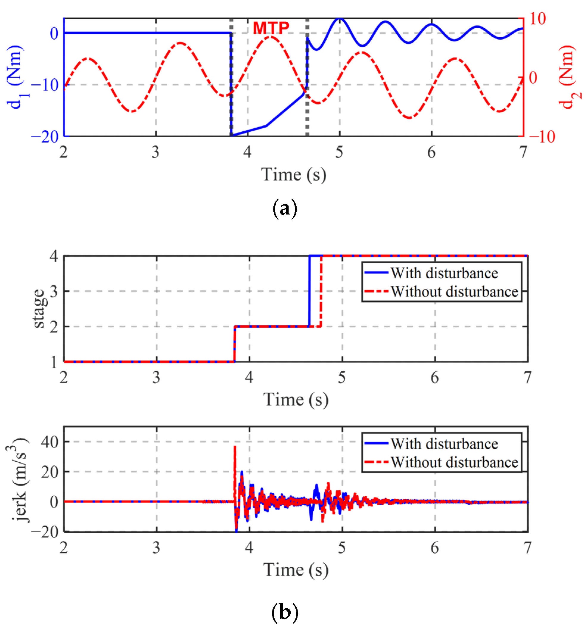
The engine remains inactive in pure electric mode, and the primary disturbance originates from external loads. During the transition, the engine must be cranked and started by the motor; at this point, its output torque acts as a starting resistance torque. In hybrid mode, however, the engine can generate torque, while the disturbance primarily stems from external loads. Different stages of PS-HEV have different disturbance types. During pure electric mode, the disturbance mainly includes the external disturbance of the output shaft. During MTP, disturbance mainly includes the engine starting resistance torque and the external disturbance of the output shaft. During hybrid electric mode, the disturbance mainly includes the external disturbance of the engine and the output shaft. The disturbances acting on the engine and the output shaft are nonlinear and stochastic. For instance, the upper and lower bounds of disturbance d1 can be set to [−20,5], while those of d2 can be set to [−10,10]. This is mainly due to the negative starting torque of the engine, which is typically obtained from lookup tables. After engine start-up, the torque disturbance on the engine output shaft can be modeled by a nonlinear function with a frequency of 1 Hz. In addition, disturbances on the output shaft can be simulated using a nonlinear function with a frequency of 2 Hz, as shown in Figure 3a. Traditional MTP controllers are prone to elongating the mode transition time and generating large jerks when disturbed, as shown in Figure 3b.
In addition, the disturbance characteristics vary with different operating modes throughout the transition process, making a fixed observer gain of LESO ineffective for accurate tracking.
If we let x1 = θ, x2 = θ ˙ , then Equation (1) can be expressed as
x ˙ 1 = x 2 x ˙ 2 = D + I 1 T
where D = C I 1 x 2 K I 1 x 1 + I 1 d .
If we define x3 = D, then we construct LESO [20] for (6) as follows:
x ^ ˙ 1 = x ^ 2 + β 1 x 1 x ^ 1 x ^ ˙ 2 = D ^ + I 1 T + β 2 x 1 x ^ 1 x ^ ˙ 3 = β 3 x 1 x ^ 1
where β1, β2, and β3 are the gain of LESO.
At the same time, the estimation of disturbance can be shown in Figure 4. In Figure 4 d1 and d2 represent disturbances at the engine side and the output shaft side, respectively. Specifically, in the pure electric mode, the engine remains off and d1 = 0, with vehicle disturbances arising solely from external loads. During the mode transition process, the engine is started by the motor, and the disturbance manifests as a starting resistive torque, while external loads remain present. In the hybrid mode, the engine generates torque and experiences a small inertial resistance, but the primary source of disturbance still comes from external loads. Therefore, the disturbances acting on the PS-HEV differ in type and magnitude across various operating phases, making it difficult for a fixed LESO gain to accurately estimate them. The error of d1 suddenly changes to 20 Nm, and the error of d2 fluctuates within the range of 1 Nm. The disturbance compensation is provided by the observer and implemented through the motor. However, this prevents the motor from delivering an appropriate compensating torque to the output shaft, resulting in torque fluctuations and consequently causing impact.
In conclusion, the above analysis of disturbance impacts and ESO limitations on MTP suggests two requirements for MTP control at present:
(1)
Design an MTP disturbance observer capable of adaptively adjusting the observer gain during mode transition phases to enhance observation accuracy.
(2)
Design an MTP controller whose convergence time does not depend on the initial value of the state and can converge at the expected time.

3. Predefined Time Transient Coordination Control of PS-HEV Based on Adaptive Nonlinear Extended State Observer

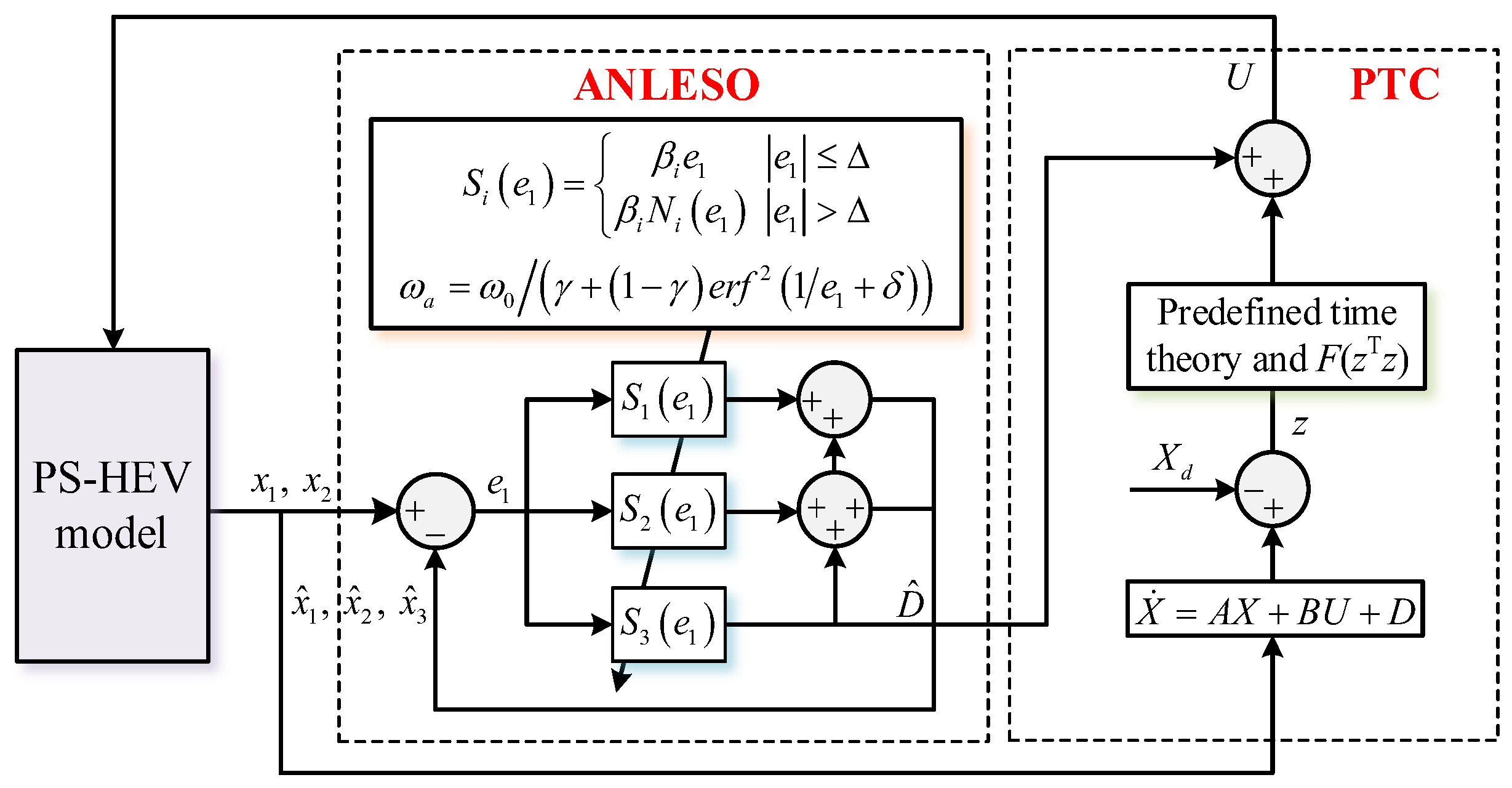
This paper develops a predefined-time transient coordination control strategy for PS-HEVs based on an ANLESO. Specifically, an ANLESO is designed to estimate external disturbances. It not only retains the advantages of the conventional LESO but also introduces nonlinear functions to enhance observation speed and accuracy. Compared with the LESO, the proposed ANLESO achieves at least a 70.2% improvement in estimation accuracy. Furthermore, a predefined-time controller is designed using predefined-time control theory and a nonsingular function, which improves convergence accuracy by at least 44.3% compared with the PID controller. By integrating disturbance estimation into the control loop, the proposed method further enhances the robustness and control precision of the system, thereby improving the quality of mode transition (Figure 5).

3.1. Design of Adaptive Nonlinear Extended State Observer

Assumption 1. 
D is known, and the uncertain disturbance satisfies the boundary condition D ≤ |K|.
Define e 1 = x 1 x ^ 1 , e 2 = x 2 x ^ 2 , e 3 = D D ^ . The preceding analysis shows that at the onset of MTP and the initial transition into the hybrid mode, the change in disturbance characteristics inevitably leads to significant estimation errors. Therefore, an adaptive nonlinear extended state observer is proposed and can be expressed as
x ^ ˙ 1 = x ^ 2 + S 1 e 1 x ^ ˙ 2 = D ^ + I 1 T + S 2 e 1 x ^ ˙ 3 = S 3 e 1
where Si(e1) is the nonlinear piecewise function, which can be defined as
S i e 1 = β i e 1 e 1 Δ β i N i e 1 e 1 > Δ
where Δ is a switching threshold. N(e1) is a nonlinear function and can be designed as
N i e 1 = e 1 / Δ exp e 1 Δ 1 2
where i = 1, 2, and 3.
lim e 1 ± Δ β i e 1 = lim e 1 ± Δ β i N i e 1
Remark 1. 
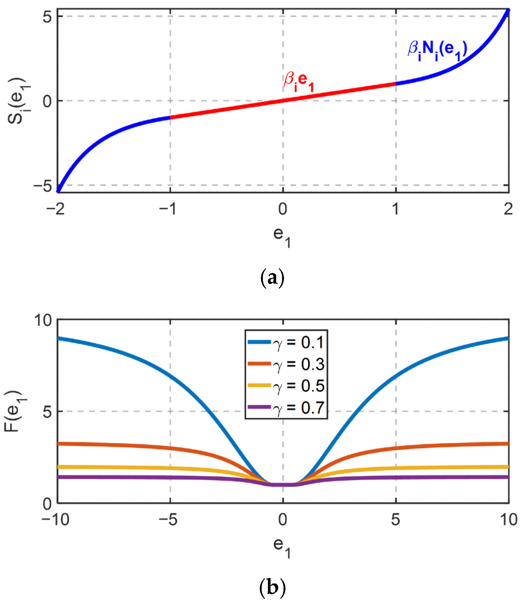
Si(e1) is a smooth nonlinear piecewise function, as shown in Figure 6a. Here, Ni(e1) is a nonlinear function. When |e1| approaches Δ, Ni(e1) approaches 1. When |e1| exceeds Δ, Ni(e1) becomes significantly larger than 1. In the strong nonlinear range of MTP, Si(e1) becomes ANLESO, which adaptively adjusts the convergence rate based on the error e1. In steady states, such as the pure electric mode or the hybrid mode, Si(e1) becomes LESO, providing more precise and faster estimates while avoiding excessive nonlinear compensation.
When |e1| ≤ Δ, Equation (7) is LESO for the different interference problems in different mode switching phases, and ESO needs to adjust the observation gain to ensure the observation accuracy adaptively.
Then Equation (7) can be re-expressed as
e ˙ 1 = e 2 β 1 e 1 e ˙ 2 = e 3 β 2 e 1 e ˙ 3 = D ˙ β 3 e 1
Equation (10) can be expressed in the form of a state space equation
E ˙ = A o E + w
where E = e 1 e 2 e 3 ,   A o = β 1 1 0 β 2 0 1 β 3 0 0 ,   w = 0 0 D ˙ .
The matrix Ao of LESO has characteristic polynomials
det s I A o = s 3 + β 1 s 2 + β 2 s + β 3
The pole placement technique can be used to design the gains of the LESO as follows:
β 1 = 3 ω 0 ,   β 2 = 3 ω 0 2 ,   β 3 = ω 0 3
Adaptive bandwidth design is formulated as follows:
ω a = F e 1 ω 0 F e 1 = 1 γ + 1 γ e r f 2 1 e 1 + δ
where γ is the adjustment coefficient, and 0 < γ < 1.
Therefore, when the observer gains in the LESO, as given in Equation (15), the formulation in Equation (7) is modified to ALESO.
Remark 2. 
F(e1) is a nonlinear smooth function of e1. When e1is small, corresponding to the steady-state condition of the system, F(e1) approaches 1. Conversely, when e1 is large, indicating a transient operating condition, F(e1) approaches 1/γ. The parameter γ is used to adjust the amplification factor of the bandwidth gain. When e1 remains constant, reducing γ can further increase the value of F(e1), as shown in Figure 6b. Furthermore, regardless of whether e1 is positive or negative, F(e1) can ensure symmetrical convergence. Since the constant terms in Si(e1) are fixed, it can be further transformed into:
S i e 1 = β i C e 1 e 1 C e 1 = 1 e 1 Δ 1 / Δ exp e 1 Δ 1 2 e 1 > Δ
Then, the nonlinear observer can be expressed as
e ˙ 1 = e 2 β 1 C e 1 e 1 e ˙ 2 = e 3 β 2 C e 1 e 1 e ˙ 3 = D ˙ β 3 C e 1 e 1
The characteristic equation of the system (17) is
s 3 + β 1 C e 1 s 2 + β 2 C e 1 s + β 3 C e 1 = 0
According to [21], the observer transfer function can be regarded as a variable-coefficient linear system with parametric perturbations. Its stability can be analyzed using the Routh criterion. According to the Routh criterion, the stability condition of the system is
β 1 C e 1 > 0 β 1 C e 1 > 0 β 1 C e 1 > 0 β 3 β 2 C 2 e 1 > β 1 C e 1
By differentiating C(e1), we obtain
C ˙ e 1 = 0 e 1 Δ 2 e 1 exp e 1 Δ 1 2 e 1 Δ 1 Δ e 1 e 1 > Δ
From Equation (20), it can be observed that when −Δ ≤ e1 ≤ Δ, C ˙ (e1) is 0, and C(e1) equals 1. When e1 > Δ, C ˙ (e1) is greater than or equal to 0, resulting in C(e1) > 1. Similarly, when e1 < −Δ, the term is less than or equal to 0, yet C(e1) remains greater than 1. Therefore, since C(e1) is always greater than 1, the stability of ANLESO is ensured if the parameters satisfy Equation (21). Then, the proof is obtained.
β 1 > 0 β 1 > 0 β 1 > 0 β 3 β 2 > β 1

3.2. Design of MTP Predefined-Time Controller

Finite-time controllers can improve mode transition speed; however, their convergence time depends on the initial state values, and thus, they cannot ensure synchronized convergence of the engine and output shaft speeds [22]. Therefore, in this study, a prescribed-time controller independent of the initial states is designed to guarantee synchronous convergence of both the engine and output shaft speeds, thereby enhancing both the convergence speed and tracking accuracy.
Lemma 1. 
(See [23]) If there exists a Lyapunov function V that complies with
V ˙ π r T c V 1 + r 2 + V 1 r 2 + b
where 0 < r < 1, Tc and b are positive constants, and V is practically predefined time stable with the predefined time 2Tc.
The MTP predefined-time controller primarily consists of a control model design, a predefined-time controller design, and a stability proof.
Step 1: To achieve speed tracking while reducing vibration between shafts, the following tracking error is defined based on the engine speed, output shaft speed, and angular displacement difference:
x = θ ˙ e θ ˙ c 1 θ e θ c 1 θ ˙ r 2 θ ˙ o u t θ r 2 θ o u t T .
The following control inputs are defined with motor MG1 and MG2 as the control inputs:
u = T m g 1 T m g 2 T .
Then, we can get the following equation:
X ˙ = A X + B U + D
where
A = c e c 1 / I e c e c 1 / I e k e c 1 / I e 0 0 0 I A I A I A I b c r 2 o u t I b c r 2 o u t I b k r 2 o u t 1 1 0 0 0 0 I B I B I B I d c r 2 o u t I d c r 2 o u t I d k r 2 o u t 0 0 0 c r 2 o u t / I o u t c r 2 o u t / I o u t k r 2 o u t / I o u t 0 0 0 1 1 0 ,
B = 0 k 2 I b 0 k 2 I d 0 0 0 I a 1 + k 1 + I b 0 I c 1 + k 1 + I d 0 0 T ,
D = 0 0 0 0 1 / I o u t T o u t + d 2 0 1 / I e T e + d 1 0 0 0 0 0 T ,
Step 2: A predefined-time controller is designed based on the backstepping method to ensure that MTP converges and stabilizes within the predefined time, enabling a smooth transition to the hybrid electric mode.
Define z = XXd, and X d = θ ˙ e d θ ˙ e 0 θ ˙ o u t θ ˙ o u t d 0 T .
Define the following Lyapunov function as
V = 1 2 z T z
Derivation of the above equation yields
V ˙ = Z T A X + B U + D X ˙ d
Thus, U can be designed as
U = B 1 A X + D ^ X ˙ d + π r T c z z T z r 2 + π r T c F z T z z z T z r 2 + 1 2 z
where k1 and k2 are the gain of the controller, F(zTz) is the piecewise function which can address the nonsingular term z T z   r 2 , and can be expressed as
F z T z = exp z T z ε 1 exp 1 1 z T z ε 1 z T z > ε
where ε is a minimal value greater than zero.
Step 3: Proof of stability
Theorem 1. 
Consider the MTP system (23) with controller (26); its error can converge into a sufficiently small region around the origin within a predefined time Tc.
Proof. 
When z T z ε , we can get
V ˙ = z T π r T c z z T z r 2 π r T c F z T z z z T z r 2 1 2 z + D D ^ = π r T c z T z 1 + r 2 + z T z 1 r 2 + ε 1 r 2 π r T c 1 e z T z ε 1 e 1 z T z ε 1 r 2 1 2 z T z + z T D ˜
where D ˜ = D D ^ , and it is bounded.
According to Young’s inequality [18], it can be concluded that
z T D ˜ 1 2 z T z + 1 2 D ˜ 2
Thus, Equation (29) can be re-expressed as
V ˙ = z T π r T c z T z r 2 π r T c F z T z z T z r 2 1 2 z + D D ^ = π r T c z T z 1 + r 2 + z T z 1 r 2 + ε 1 r 2 π r T c + 1 2 D ˜ 2
where ε 1 r 2 π r T c 1 e z T z ε 1 e 1 z T z ε 1 r 2 ε 1 r 2 π r T c when z T z > ε , we can get
V ˙ = z T π r T c z T z r 2 π r T c F z T z z T z r 2 1 2 z + D D ^ = π r T c z T z 1 + r 2 + z T z 1 r 2 + 1 2 D ˜ 2
According to Lemma 1, it is concluded from (30) and (31) that the MTP system (23) with controller (26), and its error can converge into a sufficiently small region around the origin within a predefined time Tc. □

4. Results and Discussion

The evaluation is performed by using both the HIL environment and experimental tests. The parameters of PS-HEV and ANLESO-PTC are shown in Table 1 and Table 2.

4.1. HIL Test Results and Analysis

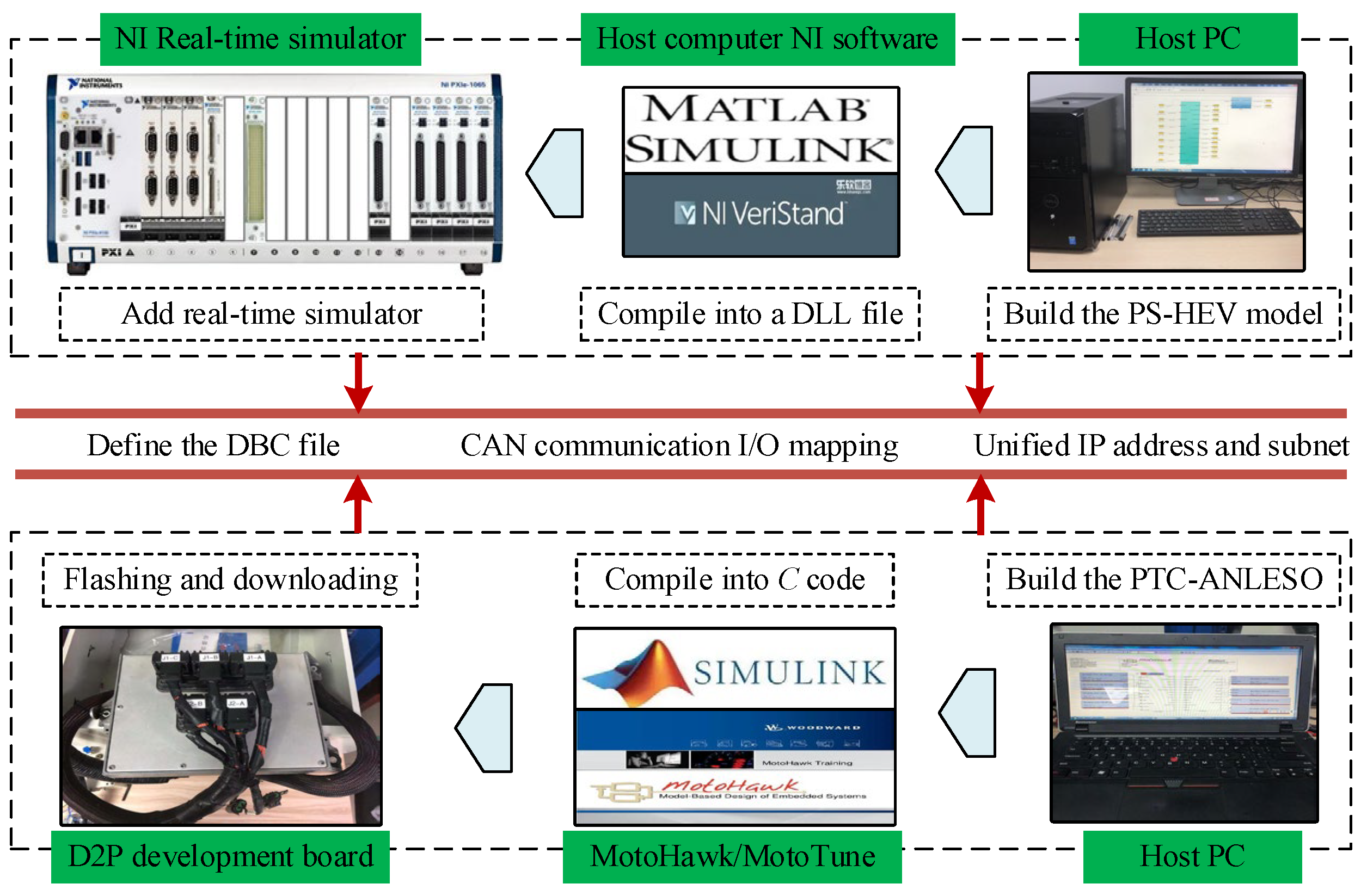
The HIL test is established, as shown in Figure 7. The PS-HEV model is built in MATLAB/Simulink, and then compiled into a DLL file and added to the NI real-time simulator. The PTC-ANLESO strategy is built in Simulink/MotoHawk, compiled into C code, and downloaded into D2P by MotoTune. The database CAN (DBC) file is compiled by CAN Db++ (3.1 SP5) software. The I/O of the D2P and NI real-time simulator can be interrupted by DBC. The signal can be communicated by CAN. The model and controller can be achieved closed loop through the above steps. The sample step of the model and controller are all set at 0.01 s. The baud of CAN communication is set at 500 Kbd to press close to the reality vehicle.
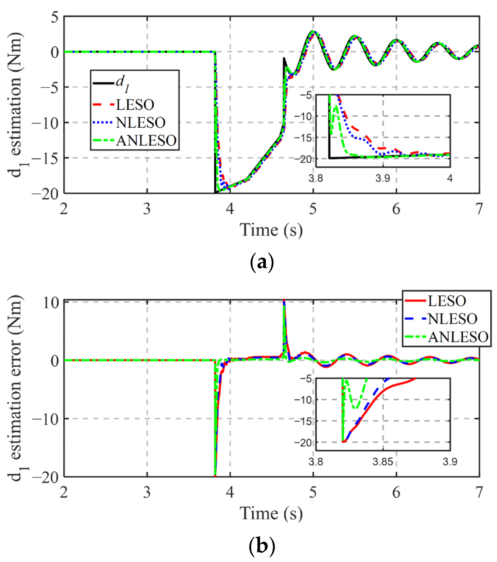
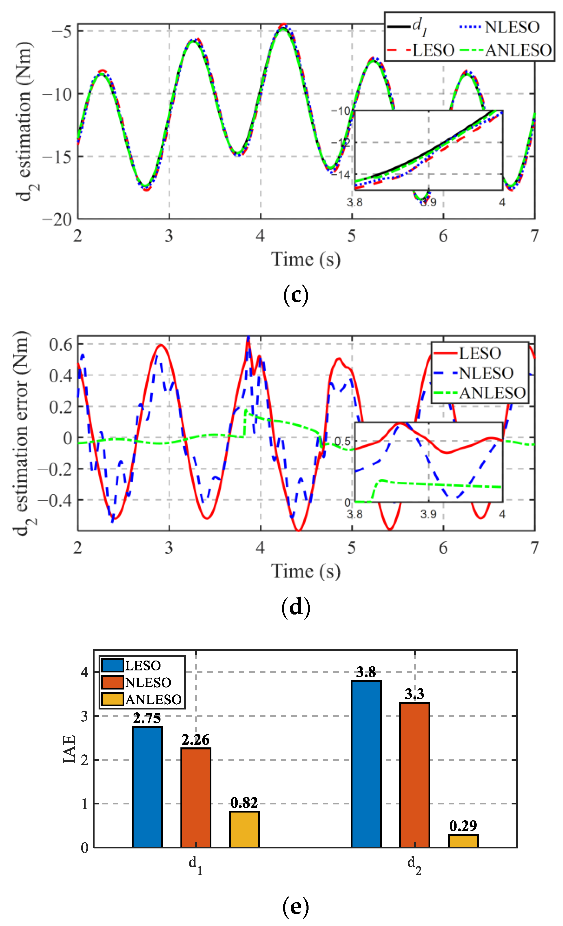
As shown in Figure 8, ANLESO is compared with LESO [19] and NLESO [20] to validate its superiority. Figure 8 illustrates the disturbance observation results under three different state observers: LESO, NLESO, and ANLESO. Figure 8a shows the estimation curves for disturbance d1, where the ANLESO observer exhibits the fastest convergence, followed by NLESO, and LESO is the slowest. Figure 8b presents the estimation error for d1, with ANLESO achieving the smallest error and LESO the largest. Figure 8c,d depict the estimation and error curves for disturbance d2, respectively. Specifically, for d2, ANLESO demonstrates the fastest convergence and the lowest estimation error, while LESO exhibits the slowest convergence and the poorest accuracy. Figure 8e compares the IAE (Integral of Absolute Error) indices for the three observers, which quantitatively measure the estimation accuracy. For the rapidly varying d1, the proposed method reduces the IAE by 70.2% compared with LESO and by 63.7% compared with NLESO. For the more slowly varying d2, the IAE is reduced by 92.1% relative to LESO and by 90.9% relative to NLESO. A total of at least 50 simulation trials was conducted for each observer. The IAE values reported in the manuscript represent the mean of these trials. Due to the highly consistent simulation platform and operating conditions, the IAE showed minimal variability across different observers. For the d1 observation, the IAE fluctuation ranges for LESO, NLESO, and ANLESO were ±0.01, ±0.008, and ±0.0015, respectively. Accordingly, the 95% confidence intervals of the IAE for LESO, NLESO, and ANLESO were 2.72 ± 0.0028, 2.26 ± 0.00227, and 0.82 ± 0.00043 (n = 50), indicating the high consistency and reliability of the observer performance.
These results indicate that all three observers—LESO, NLESO, and ANLESO—can effectively estimate disturbances. In terms of convergence speed, LESO is slower than NLESO and ANLESO due to its fixed observer gain. NLESO, which employs a nonlinear observer gain related to the estimation error, converges faster than LESO. The proposed ANLESO integrates the advantages of both NLESO and LESO: in the steady state, it adopts a LESO-like form with a gain adaptively adjusted based on the estimation error to accelerate convergence, while in the transient state, the gain also varies adaptively according to the estimation error, ensuring a faster convergence than LESO. Compared with conventional NLESO, ANLESO exhibits smoother responses and achieves exponential convergence. From the perspective of estimation accuracy, ANLESO outperforms both NLESO and LESO. This superiority arises because ANLESO dynamically adapts its observer gain in response to different disturbances, ensuring high estimation precision. Furthermore, when handling disturbances of varying magnitudes and signs, the proposed ANLESO guarantees symmetrical convergence of the estimation errors.
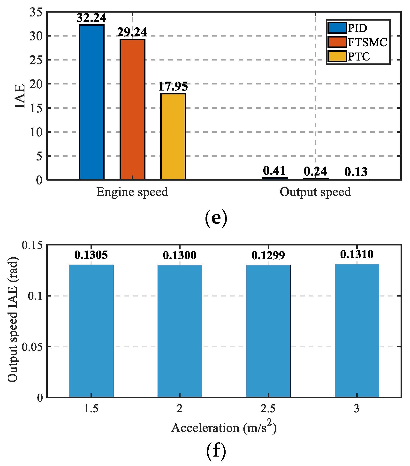
Figure 9 illustrates the tracking performance of the engine and output shaft speeds under three different control strategies. Specifically, Figure 9a,b show the engine speed tracking curves and the corresponding error curves. Under PID control, the engine speed requires 1.3 s to reach steady state, with a steady-state error of 0.81 rad/s. The FTSMC controller brings the engine speed close to the equilibrium point within 1 s, reducing the steady-state error to 0.07 rad/s. The proposed PTC is designed with a preset convergence time of 0.5 s, and the actual engine speed converges accordingly within 0.5 s, with the steady-state error being negligible. Figure 9c,d present the tracking curves and error curves for the output shaft speed. Under PTC, the output shaft speed also stabilizes within 0.5 s. In contrast, neither PID nor FTSMC can ensure simultaneous convergence of both the engine and output shaft speeds. Figure 9e shows the IAE indices, indicating that the proposed PTC achieves the smallest tracking errors for both the engine speed and output shaft speed, with values of 17.95 and 0.13 rad, respectively. Additionally, the IAE of the output shaft speed tracking under different acceleration conditions was evaluated, as shown in Figure 9f. It can be observed that the IAE remains nearly constant across accelerations of 1.5, 2, 2.5, and 3 m/s2, fluctuating around 0.13 rad.
The results in Figure 9 indicate that, for both engine speed tracking and output shaft speed tracking, PID control exhibits the slowest convergence rate and the largest steady-state error. This is primarily because the convergence speed and steady-state accuracy of PID are highly dependent on parameter tuning, making it difficult to balance accuracy and convergence rate simultaneously. In contrast, the PTC developed in this study embeds a time-dependent factor into the control law, which enforces convergence within a prescribed time. Moreover, by incorporating a nonlinear convergence law and error feedback, the proposed PTC ensures that the tracking error asymptotically approaches zero within the predefined time, with the steady-state error being theoretically negligible. In addition, both PID and FTSMC fail to guarantee simultaneous convergence of the engine speed and the output shaft speed, as their convergence times depend on the magnitude of the initial error. By comparison, the convergence time of PTC is independent of the initial error conditions. Furthermore, testing under different acceleration conditions further demonstrates the generality and reliability of the proposed control method.
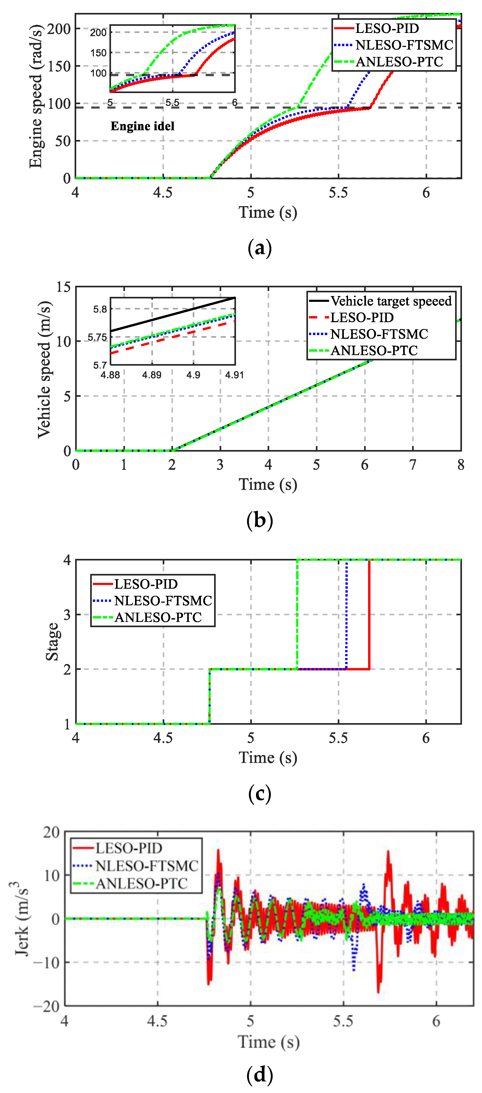
To demonstrate the superiority of the proposed ANLESO-PTC control strategy, a comparative study was conducted against the NLESO-FTSMC and LESO-PID strategies, with the results presented in Figure 10. Figure 10 illustrates the engine and output shaft speed responses, mode transition time, and impact severity of the PS-HEV under the three different control strategies. As shown in Figure 10a,c, the engine and vehicle speeds successfully reached their respective targets under all three strategies, thereby achieving smooth mode transitions. Specifically, under the LESO-PID strategy, the engine completed idle start-up between 4.76 s and 5.68 s, requiring 0.92 s. The NLESO-FTSMC strategy shortened the start-up time to 0.79 s, while the proposed ANLESO-PTC strategy required only 0.5 s. Compared with the LESO-PID strategy, the proposed method reduced the mode transition time by 45.7%. Figure 10b indicates that the proposed strategy achieves the highest convergence accuracy. Figure 10d shows that the LESO-PID strategy resulted in a peak jerk of 16.9 m/s3, which significantly exceeds the German standard limit of 10 m/s3. The NLESO-FTSMC strategy reduced the jerk to 12.2 m/s3, whereas the proposed ANLESO-PTC achieved only 6.9 m/s3. Compared with the LESO-PID strategy, the proposed method reduced the jerk by 59.2%. The detailed quantitative results are summarized in Table 3.
These results indicate that the PID-LESO control strategy exhibits limited capability in accurately regulating the engine speed under the complex MTP characteristics of the PS-HEV. In contrast, the proposed PTC guarantees that the engine speed converges to the reference value within a predefined time, thereby achieving a faster convergence rate. Moreover, due to the insufficient tracking and estimation performance of the PID controller and the LESO observer, the output shaft experiences larger jerk when subjected to disturbances. The NLESO-FTSMC mitigates these impacts by leveraging the fast convergence property of FTSMC and the improved estimation accuracy of NLESO. Comparatively, the proposed ANLESO-PTC strategy not only demonstrates an advantage in convergence speed but also significantly enhances convergence accuracy, which is primarily attributed to the rapid response capability of the nonlinear function embedded in PTC. Furthermore, the designed ANLESO is capable of maintaining high estimation accuracy and rapid convergence, even under large or small estimation errors, owing to its adaptive mechanism that dynamically adjusts the observer gain according to the magnitude of the error.

4.2. Experimental Results and Analysis

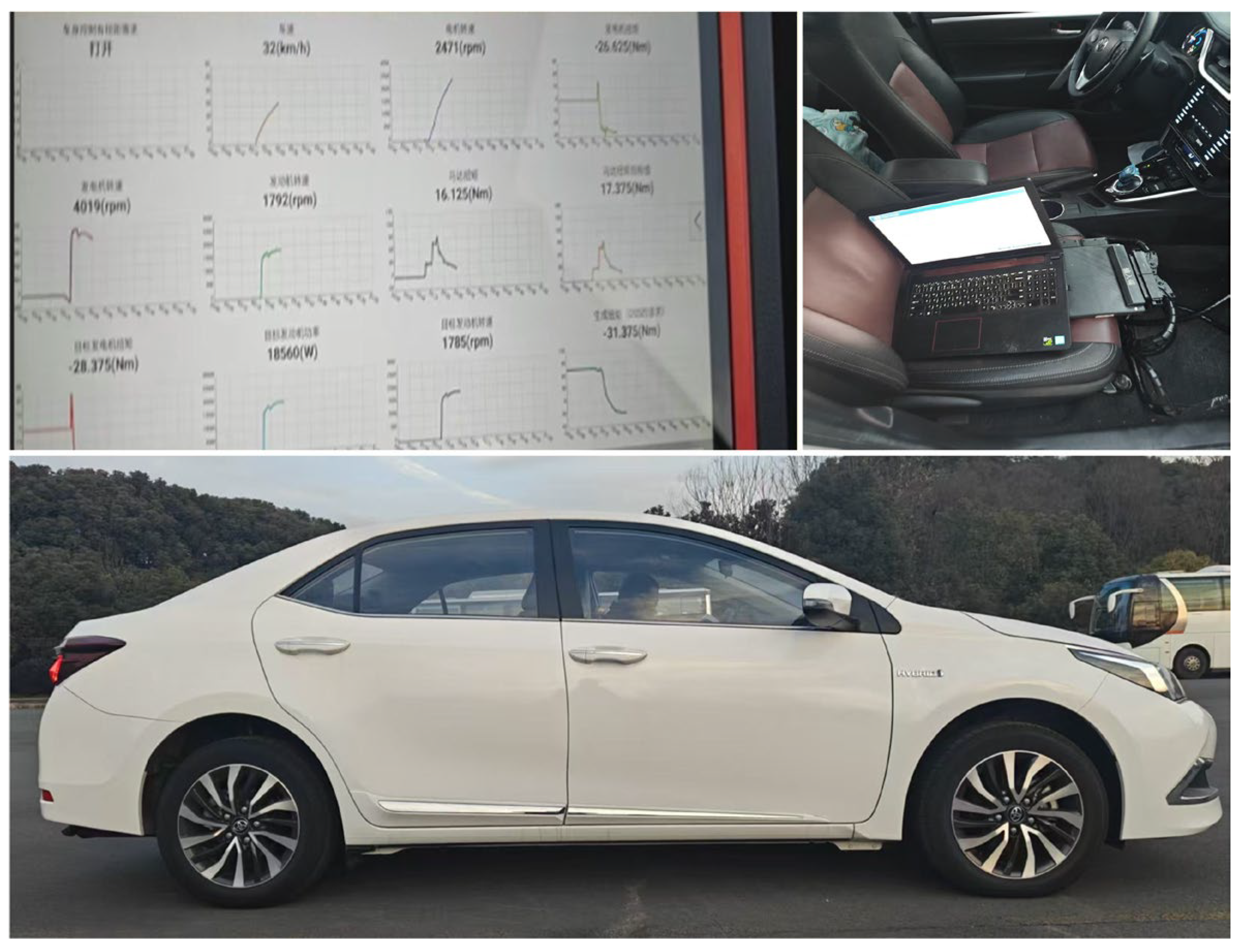
The experimental setup of the real-vehicle platform is shown in Figure 11. Due to the cost constraints of additional sensors, the experimental results are not as comprehensive as those obtained from hardware-in-the-loop (HIL) testing. It is worth noting, however, that these results are sufficient to validate the superiority of the proposed control strategy. In the real-vehicle experiments, a comparison was conducted between the baseline case using the PID control strategy and the results obtained with the proposed strategy, as illustrated in Figure 12. The proposed ANLESO-PTC control algorithm, developed in the MATLAB/Simulink environment, was compiled into C code via automatic code generation and subsequently downloaded to the vehicle control unit (VCU).
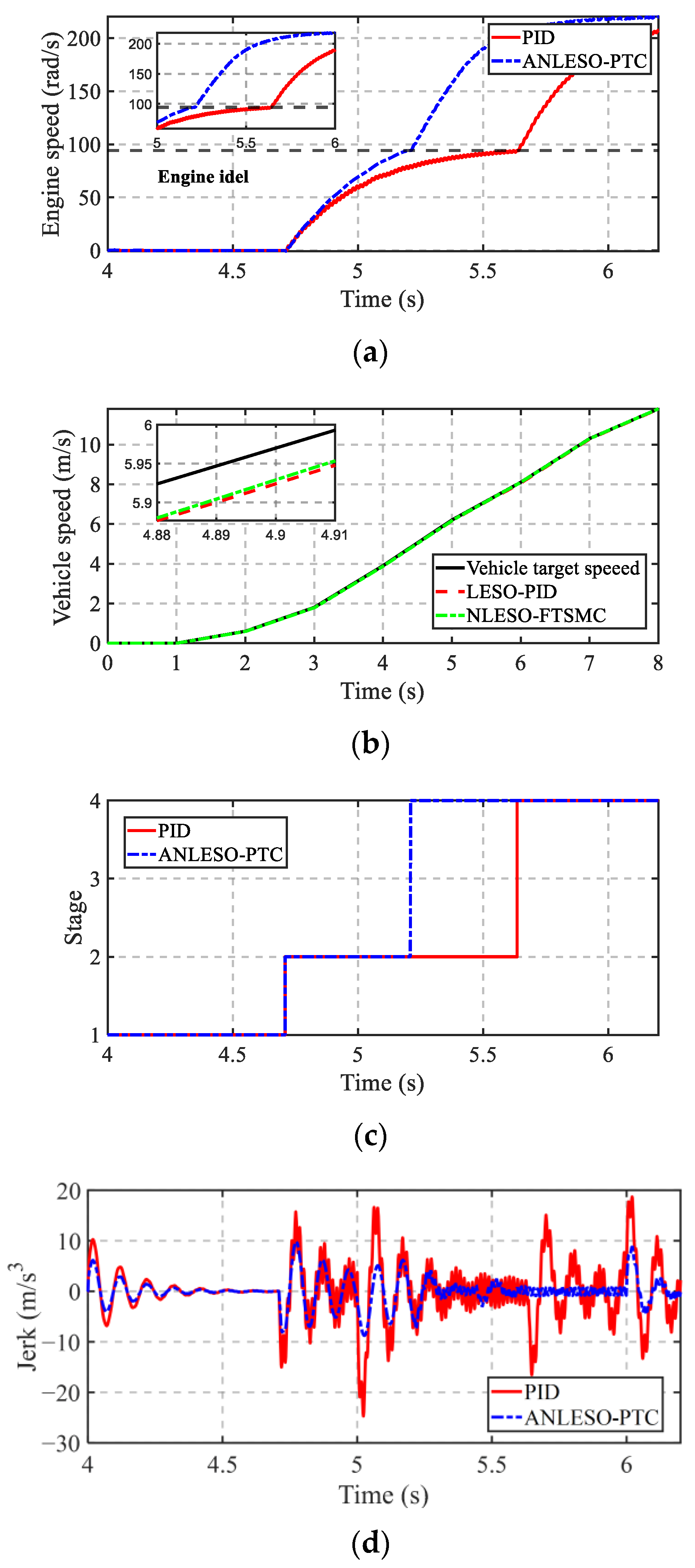
Figure 12 illustrates the evaluation metrics of MTP under real-vehicle experiments. The built-in PID-based speed tracking control of the production vehicle was compared with the proposed ANLESO-PTC strategy. As shown in Figure 12a–c, the proposed strategy achieves higher tracking accuracy and faster convergence, which highlights the rapid and precise convergence characteristics of the PTC controller. Furthermore, Figure 12d indicates that the jerk reaches a value of 24.7 m/s3 under the PID strategy, whereas the maximum value with the proposed method is only 8.8 m/s3. Although this jerk is higher than that observed in the HIL tests, it remains within the limits specified by the German standard. This improvement can be attributed to the adaptive adjustment of the observer gain in ANLESO, which is based on the magnitude of the error, thereby enhancing the accuracy of disturbance compensation. These results clearly demonstrate that the proposed control strategy can significantly improve the quality of mode transition and enhance driving smoothness.

5. Conclusions

To address the challenges posed by various disturbances during the mode transition process of power-split hybrid electric vehicles (PS-HEVs), this paper develops a predefined-time transient coordinated control strategy based on an adaptive nonlinear extended state observer (ANLESO), which significantly enhances the quality of mode transitions. The main conclusions are summarized as follows:
(1)
Based on the conventional dynamic coordinated control framework and extended state observer (ESO), this study analyzes the impact of different types of disturbances, revealing that they can severely degrade estimation accuracy and transition performance.
(2)
The proposed adaptive nonlinear extended state observer enhances the global convergence speed and accuracy of maximum torque pulsation (MTP) disturbance estimation, while guaranteeing symmetric convergence with respect to both positive/negative and large/small estimation errors. Furthermore, the predefined-time controller is designed to ensure that both engine speed and output shaft speed converge to their equilibrium points within a predefined time frame, regardless of the initial conditions.
(3)
The HIL tests conducted under three different control strategies demonstrate that the proposed ANLESO-PTC technique reduces the mode transition time by 45.7% and decreases the driving jerk by 59.2%. Furthermore, real vehicle validation confirms that the proposed control strategy can effectively limit the mode transition jerk within 10 m/s3. Overall, the proposed control strategy significantly improves the quality of mode transitions and enhances driving smoothness.
The proposed control strategy not only provides a new perspective on mode transition control for hybrid electric vehicles under disturbance conditions but also offers valuable insights for future research on transient dynamic control. Future work will focus on exploring control strategies with higher adaptability and broader applicability under complex driving conditions. In addition, the stability and long-term reliability of the proposed controller will be further investigated.

Author Contributions

Conceptualization, H.Z. and Y.Z.; software, H.Z.; validation, H.Z., H.Y. and F.Z.; Investigation, H.Z. and H.Y.; Data curation, H.Z., H.Y. and F.Z.; Writing—original draft, H.Z.; Writing—review & editing, H.Z., H.Y. and Y.Z.; Supervision, Y.Z.; Project administration, Y.Z. All authors have read and agreed to the published version of the manuscript.

Funding

This research was sponsored by the QingLan Project of Jiangsu Higher Education Institutions (JSQL2023), the National Natural Science Foundation of China (51575238), and Major scientific research projects of Changzhou Vocational Institute of Mechatronic Technology (2023-ZDKYXM-11).

Data Availability Statement

The original contributions presented in this study are included in the article. Further inquiries can be directed to the corresponding author.

Conflicts of Interest

The authors declare that they have no known competing financial interests or personal relationships that could have appeared to influence the work reported in this paper.

Nomenclature

ANLESOAdaptive nonlinear extended state observer
ANLESO-PTCPredefined-time control based on an adaptive nonlinear extended state observer
CVTContinuously variable transmission
DHTDedicated hybrid transmission
FTSMCFinite-time terminal sliding mode control
HEVHybrid electric vehicle
HILHardware-in-the-Loop
IAEIntegral of absolute error
LESOLinear extended state observer
LESO-PIDProportional integral derivative based on a linear extended state observer
MTPMode transition process
NLESONonlinear extended state observer
NLESO-FTSMCFinite-time terminal sliding mode control based on a nonlinear extended state observer
PS-HEVPower-split hybrid electric vehicle
PTCPredefined-time controller
SOCState of charge
TSMTerminal sliding mode

References

  1. Bai, S.; Liu, C. Overview of energy harvesting and emission reduction technologies in hybrid electric vehicles. Renew. Sustain. Energy Rev. 2021, 147, 111188. [Google Scholar] [CrossRef]
  2. Wang, J.; Cai, Y.; Chen, L.; Shi, D.; Wang, R.; Zhu, Z. Review on multi-power sources dynamic coordinated control of hybrid electric vehicle during driving mode transition process. Int. J. Energy Res. 2020, 44, 6128–6148. [Google Scholar] [CrossRef]
  3. Rong, X.; Shi, D.; Wang, S.; Yin, C.; Li, C. Control allocation-based adaptive dynamic coordinated control of compound power-split hybrid electric vehicles. Proc. Inst. Mech. Eng. Part C J. Mech. Eng. Sci. 2025, 239, 8192–8208. [Google Scholar] [CrossRef]
  4. Zhao, Q.; Rong, X.; Shi, D. Research on switching control based sliding mode coordination strategy of hybrid electric vehicle. Proc. Inst. Mech. Eng. Part I J. Syst. Control. Eng. 2024, 238, 1872–1887. [Google Scholar] [CrossRef]
  5. Chen, L.; Wang, J.; Cai, Y.; Shi, D.; Wang, R. Mode transition control of a power-split hybrid electric vehicle based on improved extended state observer. IEEE Access 2020, 8, 207260–207274. [Google Scholar] [CrossRef]
  6. Kim, H.; Kim, J.; Lee, H. Mode transition control using disturbance compensation for a parallel hybrid electric vehicle. Proc. Inst. Mech. Eng. Part D J. Automob. Eng. 2011, 225, 150–166. [Google Scholar] [CrossRef]
  7. Gao, A.; Fu, Z.; Tao, F. Dynamic coordinated control based on sliding mode controller during mode switching with ICE starting for an HEV. IEEE Access 2020, 8, 60428–60443. [Google Scholar] [CrossRef]
  8. Wang, J.; Cai, Y.; Chen, L.; Shi, D.; Wang, S.; Zhu, Z. Research on compound coordinated control for a power-split hybrid electric vehicle based on compensation of non-ideal communication network. IEEE Trans. Veh. Technol. 2020, 69, 14818–14833. [Google Scholar] [CrossRef]
  9. Wang, J.; Wang, R.; Ding, R.; Han, Q.; Yang, W. Dynamic switching control of power-split hybrid electric vehicles based on time delay prediction and interference compensation. IEEE Trans. Power Electron. 2023, 38, 13521–13534. [Google Scholar] [CrossRef]
  10. Yang, C.; Jiao, X.; Li, L.; Zhang, Y.; Chen, Z. A robust H∞ control-based hierarchical mode transition control system for plug-in hybrid electric vehicle. Mech. Syst. Signal Process. 2018, 99, 326–344. [Google Scholar] [CrossRef]
  11. Peng, C.; Chen, L. Model reference adaptive control based on adjustable reference model during mode transition for hybrid electric vehicles. Mechatronics 2022, 87, 102894. [Google Scholar] [CrossRef]
  12. Huang, C.; Du, C.; Li, L.; Gongye, X.; Zhao, Y. Torsional vibration suppression during mode transition process in a parallel hybrid electric vehicle based on multiple model predictive control. IEEE Access 2024, 12, 197400–197411. [Google Scholar] [CrossRef]
  13. Yin, C.; Xie, Y.; Shi, D.; Wang, S.; Zhang, K.; Li, M. Sliding mode coordinated control of hybrid electric vehicle via finite-time control technique. ISA Trans. 2024, 146, 541–554. [Google Scholar] [CrossRef] [PubMed]
  14. Muñoz-Vázquez, A.J.; Fernández-Anaya, G.; Sánchez-Torres, J.D.; Meléndez-Vázquez, F. Predefined-time control of distributed-order systems. Nonlinear Dyn. 2021, 103, 2689–2700. [Google Scholar] [CrossRef]
  15. Li, Y.; Zhao, Y.; Liu, W.; Hu, J. Adaptive fuzzy predefined-time control for third-order heterogeneous vehicular platoon systems with dead zone. IEEE Trans. Ind. Inform. 2022, 19, 9525–9534. [Google Scholar] [CrossRef]
  16. Pan, J.; Han, T.; Xiao, B.; Yan, H. Predefined-time bipartite time-varying formation tracking control of networked autonomous surface vehicles via hierarchical control approach. IEEE Trans. Veh. Technol. 2024, 73, 9536–9545. [Google Scholar] [CrossRef]
  17. Yang, Y.; Li, P.; Pei, H.; Zou, Y. Design of all-wheel-drive power-split hybrid configuration schemes based on hierarchical topology graph theory. Energy 2022, 242, 122944. [Google Scholar] [CrossRef]
  18. Rong, X.; Shi, D.; Wang, S. Adaptive anti-saturation fixed-time control for PS-HEV mode transition with predefined performance. IEEE Trans. Power Electron. 2025, 40, 13852–13865. [Google Scholar] [CrossRef]
  19. Liang, C.; Xu, X.; Wang, F.; Zhou, Z. Coordinated control strategy for mode transition of DM-PHEV based on MLD. Nonlinear Dyn. 2021, 103, 809–832. [Google Scholar] [CrossRef]
  20. Li, Y.; Hu, Y.; Ma, X.; Liu, L. Sensorless control of dual three-phase IPMSM based on frequency adaptive linear extended state observer. IEEE Trans. Power Electron. 2023, 38, 14492–14503. [Google Scholar] [CrossRef]
  21. Zhang, G.; Yao, X.; Peretti, L.; Bai, J.; Gao, X.; Li, Z.; Huang, S. Smooth Nonlinear ESO-based Model-Free Predictive Current Control with an Extended Control Set for SPMSM Drives. IEEE J. Emerg. Sel. Top. Power Electron. 2025, 13, 2565–2579. [Google Scholar] [CrossRef]
  22. Shaohua, W.; Xiangwei, R.; Dehua, S.; Chunfang, Y. Research on fixed-time robust control allocation of the mode transition for CPS-HEV considering actuator uncertainties. IEEE Trans. Transp. Electrif. 2025, 1. [Google Scholar] [CrossRef]
  23. Xie, S.; Chen, Q. Adaptive nonsingular predefined-time control for attitude stabilization of rigid spacecrafts. IEEE Trans. Circuits Syst. II Express Briefs 2021, 69, 189–193. [Google Scholar] [CrossRef]
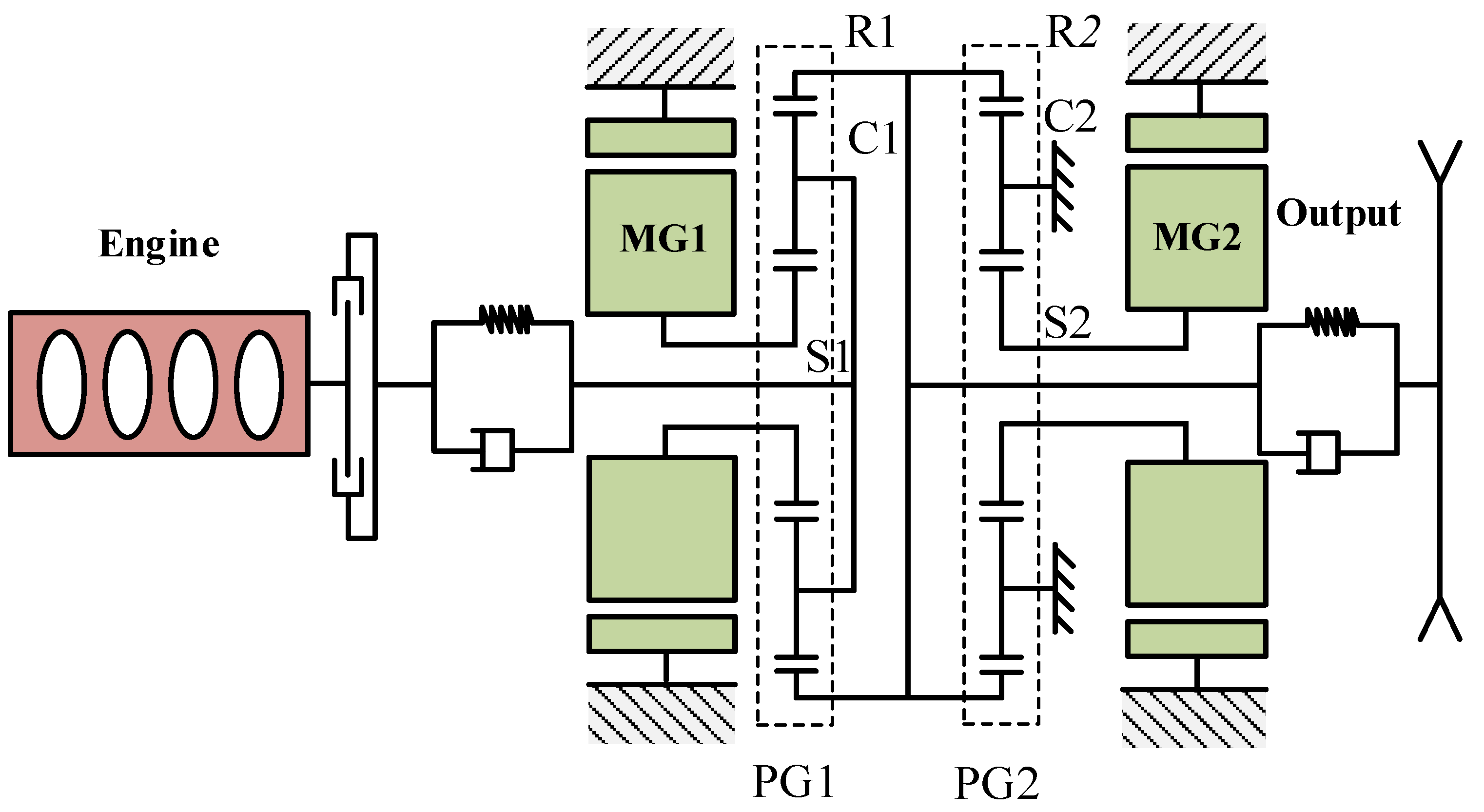
Figure 1. Schematic diagram of the PS-HEV drivetrain structure.
Symmetry 17 01751 g001
Figure 2. Mode transition logic.
Symmetry 17 01751 g002
Figure 3. Disturbance and its adverse effects on MTP. (a) Disturbance during MTP. (b) The effects of disturbance during MTP.
Symmetry 17 01751 g003
Figure 4. Estimation and estimation error of d1 and d2.
Symmetry 17 01751 g004
Figure 5. Predefined time transient coordination control of PS-HEV based on adaptive nonlinear extended state observer.
Symmetry 17 01751 g005
Figure 6. Ni(e1) and F(e1) under different m and γ. (a) Ni(e1). (b) F(e1) under different m and γ.
Symmetry 17 01751 g006
Figure 7. The schematic of the HIL.
Symmetry 17 01751 g007
Figure 8. The estimation, estimation error, and IAE of d1 and d2. (a) d1 estimation. (b) d1 estimation error. (c) d2 estimation. (d) d2 estimation error. (e). IAE under three ESOs.
Symmetry 17 01751 g008aSymmetry 17 01751 g008b
Figure 9. The speed, speed error, and IAE of the engine and output shaft. (a) Engine speed. (b) Engine speed error. (c) Output speed. (d) Output speed error. (e) IAE under three controllers. (f) Output speed IAE.
Symmetry 17 01751 g009aSymmetry 17 01751 g009b
Figure 10. The evaluation indicators of MTP under the HIL test. (a) Engine speed. (b) Output speed. (c) Stage. (d) Jerk.
Symmetry 17 01751 g010
Figure 11. PS-HEV experiment platform.
Symmetry 17 01751 g011
Figure 12. The evaluation indicators of MTP under vehicle test. (a) Engine speed. (b) Output speed. (c) Stage. (d) Jerk.
Symmetry 17 01751 g012
Table 1. The parameters of the vehicle model.
ParametersValue
Vehicle mass m1525 kg
Air resistance coefficient Cd0.31
Air density ρv1.23 m3/kg
Frontal area A2.02 m2
Rolling resistance coefficient f0.008
The radius of wheel Rr0.317 m
The ratio of the final drive i03.269
Characteristic parameter of PG1 and PG2 η1/η22.6/2.639
Engine maximum power Pe73 kW
MG1 maximum power PMG123 kW
MG2 maximum power PMG260 kW
Engine rotational inertia Ie0.13 Kg·m2
Rotational inertia of MG1 and MG2 Img1/Img20.0226/0.0326 Kg·m2
Output rotational inertia Iout15.8841 Kg·m2
Rotational inertia of R1 and R2 Ir1/Ir20.1/0.105 Kg·m2
Rotational inertia of S1 and S2 Is1/Is20.0045/0.0045 Kg·m2
Rotational inertia of C1 and C2 Ic1/Ic20.05/0.052 Kg·m2
Engine and output shaft end damping cec1/cr2out0.2/12 N/(m/s)
Engine and output shaft end stiffness kec1/kr2out10,000/2000 N/m
Table 2. The parameters of the controller model.
ParametersValue
γ[0.5, 0.5, 0.5, 0.5]
ω0[100, 0, 0, 100]
Δ[2, 0, 0, 2]
ε[1, 1, 1, 1, 1, 1]
Tc[0.5, 0.5, 0.5, 0.5, 0.5, 0.5]
r[0.01, 0.01, 0.01, 0.01, 0.01, 0.01]
Table 3. MTP evaluation indicators.
StrategyMTP TimeImproveJerkImprove
LESO-PID0.92 s-16.9 m/s3-
NLESO-FTSMC0.79 s14.1%12.2 m/s327.8%
ANLESO-PTC0.5 s45.7%6.9 m/s359.2%
Disclaimer/Publisher’s Note: The statements, opinions and data contained in all publications are solely those of the individual author(s) and contributor(s) and not of MDPI and/or the editor(s). MDPI and/or the editor(s) disclaim responsibility for any injury to people or property resulting from any ideas, methods, instructions or products referred to in the content.