Abstract
Multiplication, division, and square root operations introduce significant challenges in digital signal processing (DSP) systems, traditionally requiring multiple operations that increase execution time and hardware complexity. This study presents a novel approach that leverages binary logarithms to perform these operations using only addition, subtraction, and shifts, enabling a unified hardware implementation—a marked departure from conventional methods that handle these operations separately. The proposed design, involving logarithm and antilogarithm calculations, exhibits an algebraically symmetrical pattern that further optimizes the processing flow. Additionally, this study introduces innovative log-domain correction terms specifically designed to minimize computation errors—a critical improvement over existing methods that often struggle with precision. Compared to standard hardware implementations, the proposed design significantly reduces hardware resource utilization and power consumption while maintaining high operational frequency.
1. Introduction
Digital signal processing (DSP) systems perform tasks such as discrete cosine transform, fast Fourier transform, and image filtering, which require intensive use of multiplication, division, and square root operations. In a binary number system (BNS), standard hardware implementations of these computationally complex operations are expensive in terms of area, delay, and power consumption. Although fixed-point number representation can reduce these complexities, it is prone to overflow and scaling issues. On the other hand, floating-point number representation offers better precision and scaling but introduces more overhead.
The logarithmic number system (LNS) combines the advantages of fixed-point and floating-point number representations, namely, simplicity and precision. In the logarithmic domain (hereinafter referred to as the log-domain), multiplication and division are transformed into addition and subtraction, significantly simplifying hardware implementation. Despite inevitable errors in computing the logarithms of input data, log-domain arithmetic remains preferable in many DSP applications due to its benefits in reducing area, delay, and power consumption.
Two traditional methods are widely used to compute logarithms: the Taylor’s series expansion and the look-up table (LUT) [1,2]. The Taylor’s series method expresses the logarithm as an infinite sum of terms, with the first terms constituting the nth Taylor polynomial. Higher degrees of n yield more accurate approximations to the logarithm. The LUT method, in contrast, uses a complete table of logarithms for all numbers. Both methods require substantial memory, rendering them computationally inefficient. To address this, Mitchell [3] proposed a straightforward method for computing logarithms and antilogarithms using piece-wise linear approximations, which is memory-efficient and hardware-friendly, albeit at the cost of some accuracy. The logarithm error in Mitchell’s approximation ranges from 0 to , leading to corresponding absolute errors in log-domain arithmetic operations: for multiplication, for division, and for square root.
Mitchell [3] also derived a correction term to reduce the error, but this term is computationally complex as it requires the use of Mitchell’s algorithm for input data multiplication. Several approaches have been proposed to improve the accuracy of Mitchell’s approximation, broadly categorized into shift-and-add-based [4,5,6], LUT-based [7], and interpolation-based [8] methods. These approaches divide the fraction of the logarithms into uniform or non-uniform regions and compute a corresponding correction term for each region.
In this work, we investigate Mitchell’s algorithm and propose a unified hardware for computing multiplication, division, and square root operations—an approach that, to the best of our knowledge, has not been reported in the literature. Additionally, we propose a method for correcting results in the log-domain, significantly simplifying hardware design. Our contributions are twofold:
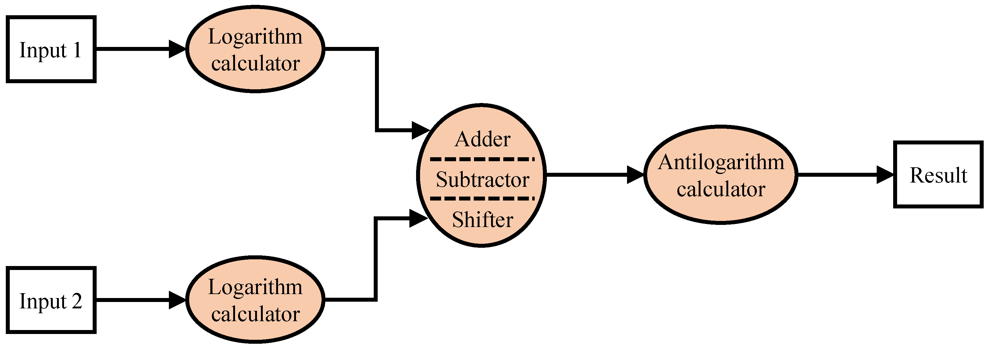
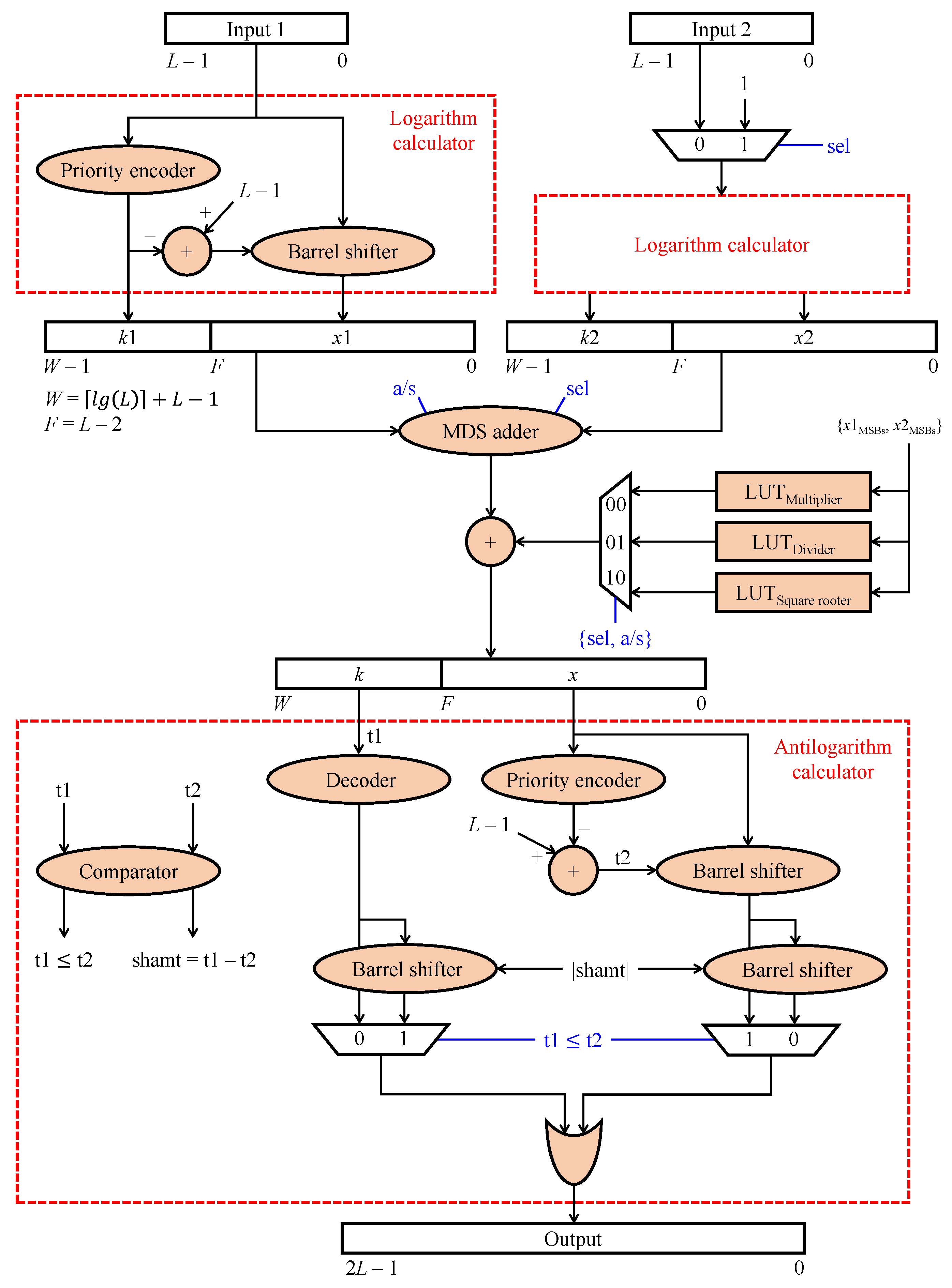
- We propose a unified and algebraically symmetrical hardware architecture capable of performing multiplication, division, and square root operations.
- We introduce a log-domain correction scheme that enhances the accuracy of these operations.
2. Related Work
Figure 1 illustrates the typical block diagram of log-domain arithmetic operations. Logarithm and antilogarithm calculations are responsible for BNS-to-LNS and LNS-to-BNS conversions, respectively, forming the basis of the algebraically symmetrical characteristic in these systems. It is noted that existing hardware designs typically support only one type of operation—multiplication, division, or square root. Therefore, depending on the operation, a corresponding circuit (adder, subtractor, or shifter) processes the logarithms to yield the final result.
Figure 1.
Block diagram of log-domain arithmetic operations.
Ahmed and Srinivas [9] utilized Mitchell’s correction term to design an iterative multiplier. By observing that truncating the least significant bits of fractional parts can reduce the hardware complexity without significantly compromising precision, they developed a fractional predictor to facilitate the computation. Also based on Mitchell’s correction term, Wu et al. [10] presented an approximate multiplier with a similar operating principle, iteratively compensating for the multiplication error. However, as mentioned earlier, the computation of Mitchell’s correction term involves input data multiplication, which increases hardware size. Additionally, these two LNS multipliers are inefficient in terms of processing speed owing to their iterative nature, requiring multiple iterations to achieve a tolerable error level.
Joginipelly and Charalampidis [11] presented an LNS multiplier optimized for filtering applications. This work could be viewed as an improvement upon the previously discussed iterative multiplier. To derive the hardware architecture, the authors sought filter weights that minimize the mean square error between the approximate and true products. The use of fixed filter weights aids in achieving a low error without increasing hardware size. However, this approach also limits its applicability to general filtering applications.
Subhasri et al. [12] presented an LNS divider in which they sacrificed precision to reduce hardware complexities. More specifically, they devised an inexact subtractor, which is smaller than the standard subtractor as it ignores the carry bits from the least significant bits of the fractions. However, the reduction in hardware utilization is subtle, and the error slightly increases compared to Mitchell’s algorithm.
More recently, Niu et al. [13] and Kim et al. [14] extended Mitchell’s algorithm to floating-point numbers. They presented single-precision and double-precision floating-point multipliers and demonstrated their application in JPEG image compression and neural network inference. Similarly, Norris and Kim [15] implemented an iterative multiplier for single-precision floating-point numbers. They used histogram stretching to demonstrate the effectiveness of employing iterative multipliers instead of exact multipliers, showing a reduction in processing time for a video.
While much research has been conducted on multipliers, most studies focus on sacrificing precision to reduce power consumption and hardware complexity. Vakili et al. [16] proposed an approach that converts fixed-point inputs to floating-point format to preserve dynamic range. They utilized LUTs to approximate multiplication in floating-point format, with a decoder converting the multiplication result back to fixed-point format. Compared to the standard multiplier across four deep learning benchmarks, their approach achieved a reduction in LUT utilization with a minimal accuracy loss of less than .
Ahmad et al. [17] leveraged two-dimensional pseudo-Booth encoding to design floating-point pseudo-Booth and floating-point iterative pseudo-Booth multipliers. They also enhanced conventional iterative multipliers with a steering circuit to reduce power consumption. These two multipliers, compared to exact floating-point multipliers, exhibited and reductions in power consumption in TSMC 180 nm CMOS technology.
AMD Xilinx and Intel FPGA (Altera), the two largest FPGA manufacturers, currently provide arithmetic IP cores for multipliers, dividers, and square rooters. However, due to the insufficient documentation from Intel FPGA regarding the implementation of these IP cores [18], we focused on the solutions provided by AMD Xilinx [19,20]. Although the specific implementation details of their multipliers are not disclosed, the dividers utilize the radix-2 non-restoring division method, and the square rooters are limited to floating-point format. While using these IP cores can greatly reduce design time and accelerate time to market, they are not always optimal in terms of delay and area. In some cases, they may even become bottlenecks in the processing pipeline.
Interestingly, no studies on LNS square rooters have been reported in the literature. Existing research has primarily focused on developing LNS multipliers and dividers separately. In response to this gap, the following section introduces a unified hardware design featuring a multiplication-division-square root (MDS) adder capable of performing addition, subtraction, and shifting operations. This integration allows for the consolidation of all primary LNS arithmetic operations into a single design. Additionally, we derive correction terms for each operation and demonstrate that our proposed design substantially reduces error compared to Mitchell’s algorithm.
3. Proposed Design
3.1. Mitchell’s Algorithm-Based Logarithm Multiplication, Division, and Square Root
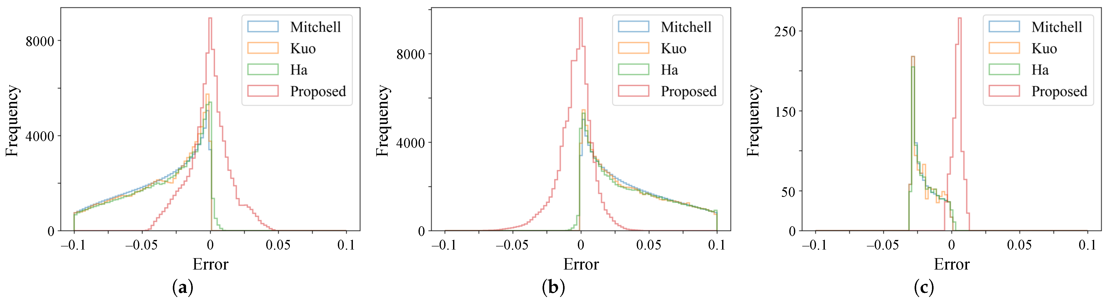
Let N be a binary number such that , where and . The binary representation of N is as follows:
where , is the most significant bit, and is the least significant bit. Without loss of generality, let us assume and rewrite the number N as below:
where . As , x is in the range and is called the fractional part (or fraction).
The logarithm of N is , where denotes the base-2 logarithm. Mitchell [3] utilized a straight line to approximate as , significantly reducing computational complexities. Compared with the true logarithm, Mitchell’s approximation results in an error in the range .
The product of two numbers and can be expressed in the log-domain as follows:
Using Mitchell’s approximation, the product P can be approximated as:
Depending on whether a carry bit occurs when adding the fractional parts ( and ), can be expressed as follows:
According to Mitchell’s approximation, for . Taking the antilogarithm yields . As a result, the antilogarithm of Equation (6) is:
The multiplication error is defined as:
The quotient of two numbers and in the log-domain is the difference between and :
The approximation of Q is:
Similar to the multiplication case, there are two expressions of depending on the presence or absence of a borrow from the integer part.
The error in division is defined as:
In the case of the square root, let N be the radicand. The logarithm of a square root is:
The approximation is:
The error in the square root is defined as:
3.2. Error Analysis
It is evident from Equations (8), (14), and (19) that errors in multiplication, division, and square root operations stem from the fractional parts. First, consider the multiplication error in the case where , and let :
Taking the partial derivative with respect to :
Solving this equation yields:
The variable is in the range . At the two extremes, and , the multiplication error is and , respectively. The negative sign implies that the approximated product is always less than the true product. The error is maximum when , and the maximum error is .
Similarly, consider the case , with now in the range :
At the two extremes, and , the multiplication error is and , respectively. Similar to the previous case, the maximum error of occurs when .
For the division error, we investigate two cases: and . For :
Given , the division error is maximized when approaches 1. Substituting into Equation (28) yields:
Here, the maximum error is when and . The minimum error is zero when or when .
For :
Similarly, the error is maximized when :
Thus, the maximum error is achieved when and . The minimum error is zero when or when .
The analysis of the square root error is as follows:
The maximum error is approximately . The minimum error is zero when or when .
To summarize, computation errors can be as high as for multiplication, for division, and for square root. The approximated product and square root are always less than the true product and square root, as indicated by the negative sign. In contrast, the approximated quotient is always greater than the true quotient. Therefore, in this work, we correct the errors using the following equations, inspired by the work of Mclaren [21]:
Notably, performing the above corrections in the log-domain is more computationally efficient, as the division and multiplication transform into addition and subtraction:
The calculation of log-domain correction terms is challenging due to its reliance on division and logarithmic operations. Utilizing Michell’s approximation can lead to significant errors, making it less desirable for accurate computations. In this study, we propose a method that involves partitioning the fractional parts into equally spaced regions using the M most significant bits (MSBs) of the fractions. For example, with three MSBs (), the fraction x is divided into eight () equally spaced intervals: , , , , , , , and .
For each specific region , we compute the average correction term and store it in an LUT. Consequently, there are correction terms for multiplication and division, and correction terms for square root operations. Table 1, Table 2 and Table 3 illustrate these correction terms for multiplication, division, and square root when . As shown in Table 1, the correction terms for multiplication form a symmetric matrix; therefore, the number of correction terms that need to be stored in the LUT can be further reduced to . An example calculation involves dividing 15 by 3, demonstrating that the proposed correction term reduces the division error from to .
Table 1.
Correction terms for multiplication errors using the three most significant bits (MSBs) to partition the fractional parts.
Table 2.
Correction terms for division errors using the three MSBs to partition the fractional parts.
Table 3.
Correction terms for square root errors using the three MSBs to partition the fractional parts.
Figure 2 illustrates the distribution of errors for multiplication, division, and square root operations using Mitchell’s [3], Ha and Lee’s [5], Kuo’s [6] methods, and our proposed approach. The error distribution for Mitchell’s algorithm shows a left-skewed pattern in multiplication, while division and square root errors exhibit a right-skewed distribution. The corresponding mean and standard deviation pairs are , , and , respectively. Ha and Lee [5], as well as Kuo [6], have refined Mitchell’s approximation, leading to reduced errors in logarithm computations. However, their impact on log-domain arithmetic operations, depicted in Figure 2 and Table 4, shows modest improvement.
Figure 2.
Distribution of multiplication, division, and square root errors using methods by Mitchell [3], Ha and Lee [5], Kuo [6], and the proposed method. (a) Multiplication error. (b) Division error. (c) Square root error.
Table 4.
Summary statistics of multiplication, division, and square root errors using methods by Mitchell [3], Ha and Lee [5], Kuo [6], and the proposed method.
With the introduction of correction terms in our proposed method, the mean and standard deviation pairs improve to for multiplication, for division, and for square root. These adjustments result in error reductions of for multiplication, for division, and for square root. The error distributions now closely resemble a Gaussian shape, indicating that errors are predominantly centered around zero. This underscores a notable enhancement in accuracy compared to the methods of Mitchell [3], Ha and Lee [5], and Kuo [6].
Figure 3 illustrates the variation in error distributions for multiplication, division, and square root operations as the number of MSBs M varies. When only one bit is utilized, the error distributions remain skewed, resulting in minimal accuracy improvement. However, for , the errors exhibit a Gaussian-like distribution with the mean approaching zero, indicating a substantial enhancement in accuracy. Using larger values of M further improves accuracy but comes at the expense of an exponential increase in the size of the LUT, which is impractical for hardware implementation due to its exponential growth. Therefore, we opt to use for our unified hardware design.
Figure 3.
Distribution of multiplication, division, and square root errors using Mitchell’s method [3] and the proposed method with M most significant bits, . (a) Multiplication error. (b) Division error. (c) Square root error.
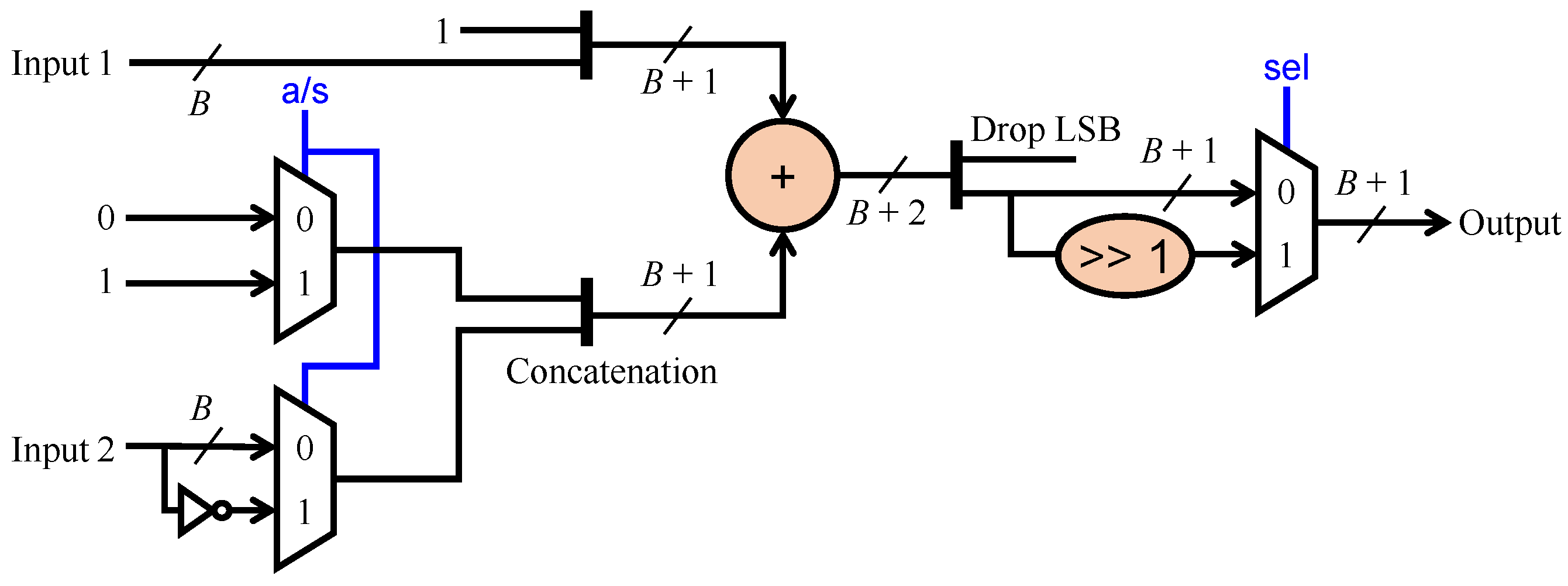
3.3. Unified Hardware Design
The proposed unified hardware follows a similar block diagram structure as depicted in Figure 1, thus retaining the inherent characteristic of algebraic symmetry. A key enhancement is the design of an MDS adder capable of executing addition, subtraction, and shifting operations, thereby establishing a unified architecture for multiplication, division, and square root computations. Figure 4 illustrates the detailed block diagram of our design, which accepts two inputs of L bits and produces an output of bits to accommodate multiplication operations.
Figure 4.
Block diagram of the proposed unified hardware design for multiplication, division, and square root.
The logarithm calculator comprises a priority encoder and a barrel shifter, implementing Mitchell’s approximation method. The computed logarithm is stored in a W-bit register, where the integer part occupies bits and the fractional part consists of bits.
To specify which operation is to be performed, we employ a 2-bit command, which is further split into two 1-bit signals, denoted as and . For binary operations, such as multiplication and division, routes the second input into the logarithm calculator. For a unary operation, like square root, selects a value of one, indicating the disregard of the second input. Regarding , the MDS adder performs addition when ; otherwise, it performs subtraction. Table 5 summarizes the operations of the proposed unified hardware design.
Table 5.
Summary of operation modes of the proposed unified hardware design.
In a naive implementation, adding or subtracting two logarithms would typically require at least two adders: one for negating the second operand in the case of subtraction, and another for adding two operands. However, in this study, we leverage the properties of two’s complement number representation to enable a single adder to handle both addition and subtraction. Figure 5 depicts the block diagram of the proposed MDS adder, where B denotes the bit size of the input data.
Figure 5.
Block diagram of the proposed multiplication-division-square root (MDS) adder.
In two’s complement representation, the subtraction is equivalent to , where is the bitwise inversion of b. In the proposed MDS adder, we pad the first input a with a 1 bit in the least significant bit (LSB) position. Similarly, after inverting the second input b, we pad with a 1 bit in the LSB position. Adding these two padded inputs ensures that a carry-in of 1 is generated, resulting in as the output of the adder. For example, considering subtracting two 4-bit numbers and :
Another example involves adding two 4-bit numbers and :
In the first example, adding 1 and 1 at the LSB position generates a carry-in of 1, implying that . In the second example, adding 1 and 0 at the LSB position generates a carry-in of 0, implying that . Therefore, the proposed MDS adder is capable of performing both addition and subtraction. In the case of square root operations, the output of the adder will be shifted to the right by one position.
Next, the output of the MDS adder is combined with a correction term obtained from one of three LUTs for multiplication, division, and square root operations, respectively. The three MSBs of the fractional parts and serve as an address for accessing the LUTs. Subsequently, the result is processed by the antilogarithm calculator. In the left branch, a decoder and a barrel shifter determine the position of the most significant 1 bit. On the right branch, a priority encoder and two barrel shifters adjust the fraction to ensure that the bits are correctly positioned. The shift amount specifies the position of the binary point, separating the integer and fractional parts. In the antilogarithm calculator, the signals and are used to represent intermediate results.
3.4. Implementation Results
We utilized Verilog HDL [22] (IEEE Standard 1364-2005) to implement the proposed unified hardware design and Xilinx Vivado v2024.1 [23] to obtain the implementation results. The target FPGA device is XCZU7EV-2FFVC1156 on a Zynq UltraScale+ MPSoC ZCU106 Evaluation Kit [24]. This device comprises a processing system (PS) and programmable logic (PL) within the same unit. The PS features an Arm® Cortex®-A53 quad-core processor, a Cortex-R5F dual-core real-time processor, and a Mali-400 graphics processing unit. The PL includes abundant configurable logic blocks (460,800 registers, 230,400 LUTs, 11 Mb block RAM, 27 Mb UltraRAM, and 1728 DSP slices) and a video encoder/decoder unit, making it well-suited for high-performance computing applications.
In Section 3.2, we analyzed errors in logarithm-based multiplication, division, and square root operations, discovering that these errors originated from the approximation of in Equation (2). Methods proposed by Ha and Lee [5] and Kuo [6] improve the approximation of , thereby reducing the errors in multiplication, division, and square root operations. Also in Section 3.2, we presented a method for reducing these errors and demonstrated its superiority over the methods by Mitchell [3], Ha and Lee [5], and Kuo [6]. Notably, our proposed unified design is the first capable of performing multiplication, division, and square root operations via a single hardware architecture, which is a definite advantage but complicates direct comparisons. Therefore, we compare our proposed design against the standard multiplier, divider, and square rooter widely utilized in the industry.
Table 6 summarizes the implementation results for 4-bit, 8-bit, 16-bit, 32-bit, and 64-bit operands. The multiplier is designed based on the split mechanism detailed in [25], while the divider and square rooter are designed following the pipeline parallelism described in [26]. Although Xilinx provides DSP macros that can synthesize multipliers, dividers, and squarers (not square rooters), these computing resources should be reserved for applications requiring intensive computations, such as neural network inference. Additionally, utilizing slice logic (registers and LUTs) instead of DSP macros not only facilitates a straightforward comparison between the proposed design and standard ones but also results in a more optimal implementation. We also included the Xilinx divider IP core in the comparison, with resource utilization information for this divider on the same Zynq UltraScale+ family obtained from [19].
Table 6.
Hardware implementation results of the standard multiplier, divider, square rooter, and the proposed unified design. NA stands for not available.
First, it is noteworthy that all designs in Table 6 follow pipeline parallelism. Therefore, the latency is the number of clock cycles required to fill the pipeline, after which new results are produced in every clock cycle. While the multiplier’s latency is two clock cycles thanks to the split mechanism, the latencies of the divider and square rooter depend on the bit size used to represent the result. To conduct a fair comparison, we use the same output bit size for all designs: specifically, 8, 16, 32, 64, and 128 bits to represent the output of 4-bit, 8-bit, 16-bit, 32-bit, and 64-bit operations, respectively. Consequently, the latencies of the divider and square rooter can be explained as follows: one clock cycle for clocking input data and 8/16/32/64/128 clock cycles for 4-bit/8-bit/16-bit/32-bit/64-bit division and square root operations, resulting in latencies of 9/17/33/65/129 clock cycles for these two designs, as well as AMD Xilinx’s divider. In sharp contrast, our proposed design only requires six clock cycles, regardless of whether the operation is multiplication, division, or square root. This efficiency is attributed to the use of logarithms, which transforms multiplication, division, and square root operations into addition, subtraction, and shift operations, which can be executed in a single clock cycle.
Regarding slice logic utilization, it is evident from Table 6 that the multiplier occupies the least amount of slice logic and consumes the least power because multiplication is a relatively simple operation. However, as the operand bit size increases, the maximum frequency decreases sharply, from MHz for 4-bit multiplication to MHz for 64-bit multiplication. Division and square root operations are more complex and thus require a substantial amount of slice logic for implementation. These two designs consume more power than the other designs but operate faster. Except for the simple multiplier, our proposed design is superior to the divider and square rooter in terms of slice logic utilization and power consumption. Although it is inferior to these two in terms of maximum frequency, it is noteworthy that the maximum frequency attained by our proposed design is adequate for most high-performance computing applications.
Overall, the implementation results demonstrate the efficacy and necessity of our proposed unified design.
4. Conclusions
In this paper, we presented a unified and algebraically symmetrical hardware design capable of performing multiplication, division, and square root operations by leveraging the properties of binary logarithms. To address the errors caused by approximations in logarithm calculations, we proposed the use of correction terms, which resulted in significant improvements in accuracy. We implemented the proposed unified design and compared it with standard multipliers, dividers, and square rooters. The implementation results demonstrated that our design is more efficient in terms of slice logic utilization and power consumption while maintaining operation at an acceptably high frequency, making it highly suitable for high-performance DSP applications.
While the proposed correction terms were calculated as average values over specific intervals, it is possible to further reduce computation errors by narrowing the interval or even using point-wise correction terms. However, this approach poses a significant challenge due to the substantial number of LUTs required for storage. Another direction for future work is to refine the approximation of using polynomial or piece-wise linear regression. The regression model could provide a rough initial estimate of the logarithm, which can then be refined using an iterative method like Newton–Raphson. In future work, we will explore all these potential directions and seek a most computationally efficient way to further reduce computation errors.
Author Contributions
Conceptualization, B.K.; software, D.N.; validation, D.N.; data curation, S.H.; writing—original draft preparation, D.N.; writing—review and editing, D.N., S.H. and B.K.; supervision, B.K. All authors have read and agreed to the published version of the manuscript.
Funding
This was supported by Korea National University of Transportation Industry-Academy Cooperation Foundation in 2024.
Data Availability Statement
Dataset available on request from the authors.
Acknowledgments
The EDA tool was supported by the IC Design Education Center (IDEC), Korea.
Conflicts of Interest
The authors declare no conflicts of interest.
References
- Arnold, M.G.; Collange, C. A Real/Complex Logarithmic Number System ALU. IEEE Trans. Comput. 2011, 60, 202–213. [Google Scholar] [CrossRef]
- Chaudhary, M.; Lee, P. An Improved Two-Step Binary Logarithmic Converter for FPGAs. IEEE Trans. Circuits Syst. II Express Briefs 2015, 62, 476–480. [Google Scholar] [CrossRef]
- Mitchell, J.N. Computer Multiplication and Division Using Binary Logarithms. IRE Trans. Electron. Comput. 1962, EC-11, 512–517. [Google Scholar] [CrossRef]
- Kuo, C.; Juang, T. Design of fast logarithmic converters with high accuracy for digital camera application. Microsyst. Technol. 2018, 24, 9–17. [Google Scholar] [CrossRef]
- Ha, M.; Lee, S. Accurate Hardware-Efficient Logarithm Circuit. IEEE Trans. Circuits Syst. II Express Briefs 2017, 64, 967–971. [Google Scholar] [CrossRef]
- Kuo, C. Design and realization of high performance logarithmic converters using non-uniform multi-regions constant adder correction schemes. Microsyst. Technol. 2018, 24, 4237–4245. [Google Scholar] [CrossRef]
- Jana, B.; Roy, A.S.; Saha, G.; Banerjee, S. A Low-Error, Memory-Based Fast Binary Logarithmic Converter. IEEE Trans. Circuits Syst. II Express Briefs 2020, 67, 2129–2133. [Google Scholar] [CrossRef]
- Makimoto, R.; Imagawa, T.; Ochi, H. Approximate Logarithmic Multipliers Using Half Compensation with Two Line Segments. In Proceedings of the 2023 IEEE 36th International System-on-Chip Conference (SOCC), Santa Clara, CA, USA, 5–8 September 2023; pp. 1–6. [Google Scholar] [CrossRef]
- Ahmed, S.; Srinivas, M. An Improved Logarithmic Multiplier for Media Processing. J. Signal Process. Syst. 2019, 91, 561–574. [Google Scholar] [CrossRef]
- Wu, X.; Wei, Z.; Ko, S.B.; Zhang, H. Design of Energy Efficient Logarithmic Approximate Multiplier. In Proceedings of the 2023 5th International Conference on Circuits and Systems (ICCS), Huzhou, China, 27–30 October 2023; pp. 129–134. [Google Scholar] [CrossRef]
- Joginipelly, A.; Charalampidis, D. An efficient circuit for error reduction in logarithmic multiplication for filtering applications. Int. J. Circuit Theory Appl. 2020, 48, 809–815. [Google Scholar] [CrossRef]
- Subhasri, C.; Jammu, B.; Harsha, L.; Bodasingi, N.; Samoju, V. Hardware-efficient approximate logarithmic division with improved accuracy. Int. J. Circuit Theory Appl. 2020, 49, 128–141. [Google Scholar] [CrossRef]
- Niu, Z.; Zhang, T.; Jiang, H.; Cockburn, B.F.; Liu, L.; Han, J. Hardware-Efficient Logarithmic Floating-Point Multipliers for Error-Tolerant Applications. IEEE Trans. Circuits Syst. I Regul. Pap. 2024, 71, 209–222. [Google Scholar] [CrossRef]
- Kim, S.; Norris, C.J.; Oelund, J.I.; Rutenbar, R.A. Area-Efficient Iterative Logarithmic Approximate Multipliers for IEEE 754 and Posit Numbers. IEEE Trans. Very Large Scale Integr. (VLSI) Syst. 2024, 32, 455–467. [Google Scholar] [CrossRef]
- Norris, C.J.; Kim, S. A Use Case of Iterative Logarithmic Floating-Point Multipliers: Accelerating Histogram Stretching on Programmable SoC. In Proceedings of the 2023 IEEE International Symposium on Circuits and Systems (ISCAS), Monterey, CA, USA, 21–25 May 2023; pp. 1–5. [Google Scholar] [CrossRef]
- Vakili, S.; Vaziri, M.; Zarei, A.; Langlois, J.P. DyRecMul: Fast and Low-Cost Approximate Multiplier for FPGAs using Dynamic Reconfiguration. ACM Trans. Reconfigurable Technol. Syst. 2024. [Google Scholar] [CrossRef]
- Towhidy, A.; Omidi, R.; Mohammadi, K. On the Design of Iterative Approximate Floating-Point Multipliers. IEEE Trans. Comput. 2023, 72, 1623–1635. [Google Scholar] [CrossRef]
- Intel. Integer Arithmetic Intel FPGA IP Cores User Guide. Available online: https://www.intel.com/content/www/us/en/docs/programmable/683490/24-1/integer-arithmetic-cores.html (accessed on 26 August 2024).
- Xilinx. Divider Generator v5.1 Product Guide (PG151). Available online: https://docs.amd.com/v/u/en-US/pg151-div-gen (accessed on 26 August 2024).
- Xilinx. Vivado Design Suite Reference Guide: Model-Based DSP Design Using System Generator (UG958). Available online: https://docs.amd.com/r/en-US/ug958-vivado-sysgen-ref (accessed on 26 August 2024).
- Mclaren, D. Improved Mitchell-based logarithmic multiplier for low-power DSP applications. In Proceedings of the 2003 IEEE International Systems-on-Chip SOC Conference, Portland, OR, USA, 17–20 September 2003; pp. 53–56. [Google Scholar] [CrossRef]
- IEEE Std 1364-2005; (Revision of IEEE Std 1374-2001). IEEE Standard for Verilog Hardware Description Language. IEEE: Piscataway, NJ, USA, 2006. [CrossRef]
- Xilinx. Vivado Design Suite User Guide: Release Notes, Installation, and Licensing (UG973). Available online: https://docs.amd.com/r/en-US/ug973-vivado-release-notes-install-license/Release-Notes (accessed on 21 April 2024).
- Xilinx. ZCU106 Evaluation Board: User Guide (UG1244). Available online: https://docs.xilinx.com/v/u/en-US/ug1244-zcu106-eval-bd (accessed on 25 July 2023).
- Ngo, D.; Kang, B. Taylor-Series-Based Reconfigurability of Gamma Correction in Hardware Designs. Electronics 2021, 10, 1959. [Google Scholar] [CrossRef]
- Lee, S.; Ngo, D.; Kang, B. Design of an FPGA-Based High-Quality Real-Time Autonomous Dehazing System. Remote Sens. 2022, 14, 1852. [Google Scholar] [CrossRef]
Disclaimer/Publisher’s Note: The statements, opinions and data contained in all publications are solely those of the individual author(s) and contributor(s) and not of MDPI and/or the editor(s). MDPI and/or the editor(s) disclaim responsibility for any injury to people or property resulting from any ideas, methods, instructions or products referred to in the content. |
© 2024 by the authors. Licensee MDPI, Basel, Switzerland. This article is an open access article distributed under the terms and conditions of the Creative Commons Attribution (CC BY) license (https://creativecommons.org/licenses/by/4.0/).