Article

Analysis of Asymmetric Wear of Brake Pads on Freight Wagons despite Full Contact between Pad Surface and Wheel

1
Department of Automation and Computer Telecontrol of Trains, Ukrainian State University of Railway Transport, Feuerbach Square 7, 61050 Kharkiv, Ukraine
2
Department of Transport and Handling Machines, Faculty of Mechanical Engineering, University of Žilina, Univerzitná 8215/1, 010 26 Žilina, Slovakia
3
Department of Wagon Engineering and Product Quality, Ukrainian State University of Railway Transport, Feuerbach Square 7, 61050 Kharkiv, Ukraine
*
Author to whom correspondence should be addressed.
Symmetry 2024, 16(3), 346; https://doi.org/10.3390/sym16030346
Submission received: 20 January 2024 / Revised: 9 March 2024 / Accepted: 11 March 2024 / Published: 13 March 2024

Abstract

:
This article presents the results of a study focused on identifying the main causes of the asymmetric (clinodual) wear of composite brake pads on freight wagons. A new scientific approach to determining the clinodual wear of composite brake pads on freight wagons is proposed. It is established that the harmful abrasion of the pad occurs during the movement of the freight train due to an imperfection in the bogie-brake lever transmission. The causes of the non-normative frictional wear of composite brake pads were investigated. This kind of wear leads to the tilting and abutting of the upper end of the brake pads against the rotating wheel during train running. The results of geometric and kinetostatic studies of the “pad–wheel” tribotechnical pair are provided to establish the causes and consequences of the accelerated clinodual frictional wear of composite brake pads on pendulum suspension in the bogies of freight wagons. The conditions of rotation of the wheels during braking “for” and “against” the clockwise direction depending on the direction of the train are considered. A new approach to brake-pad-wear prediction depending on the mileage of wagons under operational conditions is proposed. The research conducted in this study contributes to the development of the mechanical parts of freight-wagon brakes, increasing the efficiency of brake operation and improving the safety of train traffic.

1. Introduction

The reduction in the cost of transportation and operating costs for the maintenance of rail vehicles is very important for the sustainability of railway infrastructure [1,2,3,4,5]. The working condition and reliability of railway vehicles (RVs) play a major role. RV braking equipment significantly affects both train traffic safety and energy saving. However, there is currently a critical situation regarding the non-normative wear of composite brake pads (CBPs) in wagons. In the case of freight wagons, the harmful friction of brake pads occurs due to the slope of the surface of the brake pad making contact with the running surface of wheels when the brake is not engaged. Such friction causes harmful consequences for freight railway transportation [6,7,8]. The train’s resistance to movement increases depending on the kilowatts of electricity consumed, resulting in thousands of tons of diesel fuel being wasted. During operation, the pads wear abnormally, while their braking area decreases. This negatively affects braking efficiency and worsens the safety of train traffic.
During braking, the contact forces of pressure on clinodual-worn CBPs are distributed eccentrically along the reduced working area of friction. Due to this, significantly greater frictional forces are concentrated on its upper parts, and intense frictional heat generation is concentrated. This causes the formation of numerous forms of high-temperature damage (microcracks, shells, high scratches, etc.) on the rolling surface of the wheels. Therefore, most wagon wheel pairs are operated with such defects. Hence, the dynamics of the wheels rolling on the railway track have an additional increased resistance to movement and increased energy consumption for the traction of freight trains [9].
The operating resource of freight-wagon CBPs with a wheelset gauge of 1520 mm with formed clinodual wear is less than 50%. In this regard, they are replaced by new ones, and abnormally worn pads are removed from the wagon. These removed pads have significant remaining working mass due to a threat to traffic safety and they are taken to landfills (Figure 1) [10].
Based on a review of existing studies, in many cases, the CBPs were bent and rubbed their upper ends against the wheels during operation for short distances, even in freight wagons that were put into operation directly from wagon-building factories or wagon-repair enterprises, meaning that the mechanisms designed to ensure the uniform wear of the pad surfaces no longer perform as intended.
The operation problems and appointment of the terms of maintenance and repair of freight-wagon brake systems related to the elimination of the phenomenon of non-normative wear of brake pads have not yet been sufficiently studied. From this point of view, the scientific and technical studies dedicated to this problem have been carried out for many years as part of the research and development work of the authors’ team [11,12,13]. One way or another, the successful solution to this problem relates to the improvement in the mechanical brake system of freight wagons. In particular, it relates to the determination of force factors for the clinodual wear of freight-wagon brake pads.
Therefore, there is a need to create measures aimed at solving the problem of the clinodual wear of CBPs in freight wagons.
The problem of the uneven wear of brake pads arose at the beginning of the use of cast structures in three-element bogies, MT-50 and TsNII-X3, which became associated with a decrease in the performance of brake pads due to clinodual wear. Many works are devoted to the study of the causes and consequences of this phenomenon. It is necessary to single out the work of [14], which states that the number of redundant connections that prevent the self-installation of the brake pads in the bogie relative to the rolling surface of the wheels after the brakes are applied reaches significant values, namely 12; therefore, it was recommended to make design changes to tighten the vertical levers of the bogie to reduce these values. However, such a proposal has not been brought to operational perfection and has not been implemented in practice. This solution would not only contribute to the self-alignment of the pads relative to the rolling surface of the wheelsets, but it would also increase braking efficiency in curved sections of a track.
It was determined in [15] that the configuration of the brake lever transmission (BLT) currently used in two-axle freight bogies does not ensure CBP wear to the minimum permissible value in operation without additional manual adjustments by installing brake pads of the maximum thickness. However, the authors of the article did not address the issue of the non-normative wear and tear of the CBPs.
The research presented in [16] covers the methodology of estimating the brake-pad pressures, including a structural analysis of the BLT mechanism, the determination of the positions of the links based on the coordinate method, and force analysis. The study was carried out with nominal pad sizes and different wheel diameters. However, the research did not consider issues related to clinodual frictional wear and its effect on brake pressure forces.
The work in [17] focuses on the justification of the coordination of dimensional chains of freight wagons to determine the nature of freight-wagon brake-pad-wear intensity. A methodology for calculating the dimensional chains of the CBPs is proposed, which allows the determination of the limit deviations of the component links for brake pads that wear out evenly.
The authors’ team presents in [18] the results of comparative tests of different types of brake pads of Ukrainian and foreign productions in freight wagons. Tests of brake pads from a domestic manufacturer and pads made in the USA confirmed their ability to reduce the number of defects on the wheel rolling surface. However, it should be noted that the existing design and operation of the BLT of the freight-wagon bogie contributes to the formation of clinodual wear of any type of brake pad, regardless of the manufacturer [19,20,21].
The study of scientific and technical sources about the performance of BLTs of modern freight wagons proves that none of the latest BLT bogie designs [22,23,24] solve the problem. This is due to the fact that BLT developers proposed the creation of a variety of auxiliary devices for counteracting the forces that tilt the pads to rest against the wheels in the bogies; however, these devices were only based on a kinetostatic analysis of the BLT mechanism.
The work in [23] highlights the results of operational tests of a new Chinese bogie design (model ZK1) with the BLT. In this bogie, a change in the mounting of the triangle was made by relying on guide brackets specially cast in the side frames of the bogie. However, this difference in the BLT fastening design has significant disadvantages. This relates to a significant intervention in the design of the most responsible load-bearing parts of the bogie cast in the side frames. Likewise, the reliability of the specified cast-in brackets under the conditions of load dynamics in the non-suspended parts of the bogie acting from the brake system will be reduced in comparison with the general reliability of the side frames. Fatigue cracks can occur in the points of contact of the triangle spike with the side frame, which poses a threat to traffic safety. In addition, it is possible to predict increased wear of rubber bushings and a decrease in their performance during operation. Fastening the BLT in the bogie generates the risk of detachment and loss of the triangular components on the track [25,26,27,28,29,30,31,32].
Specialists and scientists from different countries have carried out a significant amount of research on BLTs. Based on these studies, various BLT devices and mechanisms have been developed to eliminate or slow down the intensive wear of brake pads. A device for the removal of freight-wagon brake pads with the automatic correction of the relative position of the brake pads relative to the rolling surfaces of the wheels is proposed in [33]. However, such a device complicates the BLT and requires periodic time-consuming adjustments in operating conditions. Due to this, the use of this device has not become practical.
The studies in [34,35] propose improvements in the designs of wagons regarding tribotechnical units and innovative materials that influence the safety of train traffic, efficient operation of brakes, and operating costs of freight wagons. From the point of view of the application of such structures, the train running speed is significantly increased; furthermore, the axial load of the wagons is significantly increased, the resource of tribotechnical parts is increased, and the operation of railway vehicles brakes is improved. However, there are several issues related to the non-standard wear of freight-wagon brake pads, which need special attention for their successful application [36,37]. Therefore, problems related to the abnormal wear of freight-wagon brake pads remain relevant [38,39]. To solve them, it is advisable to modernize the elements of the BLT in order to improve the operational reliability of the brakes and increase the safety of train movement in railway transport [40,41].
The studies in [42,43] highlight the peculiarities of the operation of brake pads and specify the requirements of materials for their production. It is noted that they should have high strength and wear resistance to prevent the destruction of brake pads; moreover, they should have sufficient hardness to ensure minimal wear of the wheel during braking [44]. This can be achieved by a change in the brake-pad material. However, the frictional properties of the brake pads must have an appropriate friction coefficient, which will make it possible to perform appropriate braking and stop the train with the shortest braking distance in case of extreme situations.
Based on a review of the literature, we established that the issues related to the problem of the abnormal wear of freight-wagon brake pads are quite relevant and require further research.
In this regard, the goal of this study is to research the factors that affect the asymmetric wear of brake pads of freight wagons. This research contributes to developing improvements in the mechanical parts of freight-wagon brakes, thus increasing the efficiency of brake operation and the safety of train traffic.

2. Materials and Methods

At present, a brake lever transmission system of the triangular type is used (Figure 2) on railways with a gauge of 1520 mm. Such a transmission system is equipped with composite brake pads, which have a nominal mass of 3.2 kg and the following geometric parameters: length of 340 mm, thickness of 65, and width of 80 mm. The gap between the block and the wheel should be 5 mm to 8 mm with a working device such as those presented in [45,46,47,48].
This brake lever transmission system works as follows: the load created by the brake cylinder from the horizontal lever is transmitted through the longitudinal thrust to vertical lever 1 located on the bogie. As a result, triangle 3 moves and brake-pad 4 sticks to the rolling surface of the wheels. The further movement of vertical lever 1 causes the delimiter of clearance 7 to move, which activates vertical lever 2 and, at the same time, the second pair of brake pads is pressed against the wheels [49].
The clinodual wear of brake pads occurs due to the imperfect design of the triangle structure and the low reliability of the device for uniform removal of the pads from the wheels.
Due to the self-weight design of the brake system parts, there is a gravitational force, G (Figure 3a), under the influence of which the brake pad tilts by turning the kinematic node, d, around until it is pressed by the force, U, with a value of 150 N to 200 N against the rotating wheel [10]. At the same time, the parameter, d, was obtained from the design and technological documentation for the brake lever transmission system. With the increase in frictional wear, an area of harmful abrasion, Qhw, is formed. The force, U, is distributed on this plane by the specific force, qse. Under the action of such forces, the friction force, Fff, is formed, and the force of resistance, Brf, to the rolling of the wheel arises and is realized during the wheel/rail contact.
According to a calculation scheme (Figure 3a), the following equation can be written:
G a = U b U = G a b ,
where G is the gravitational force generated by the weight of the bogie-brake-system parts, U is the force of pressing the top of the block to the wheel, a is the distance from the hinge, d, of the pendulum suspension to hinge c, a = d + c, and b is the distance from hinge c to the point of action of force G, b = c.
The force, Fff, during movement (rotation of the wheel, ω) is realized during the wheel/rail contact, which forms a harmful force of resistance to movement, i.e., Fff = Brf (Figure 3a) and, as a result, increases the energy consumption for train movement [10,50].
During braking with a pad with upper wear, the pressure force, K, on the pad causes its rotation around point A (Figure 3b). Therefore, the upper already-worn part of the brake pad moves away from the rolling surface of the wheel and does not participate in braking.
The lower part of the block is pressed against the wheel but with a shortened part. Due to this, the specific brake pressures, qsp, are redistributed unevenly along the pad. In the upper part of the pad, much larger specific braking pressures are concentrated, which gradually decrease towards its bottom. Due to this, the intensity of pad wear and the temperature of the tribotechnical steam during braking change proportionally. The resulting value of the braking force in the presence of clinodual pad wear takes the following form:
B b f = F f f = K φ K ξ D ,
where K is the force of pressing the brake pad to the wheel, φK is the friction-coefficient brake pad, and ξD is the friction area reduction factor due to clinodual pad wear.
Figure 3 shows a schematic flat view (in the form of a curved rod) of the model with an interpretation of new pad wear, which occurs due to the conditions of its suspension with an advance angle, α (Figure 3b). Here, based on the equations of statics, the sum of the moments of force for the brake lever equals zero ∑M(e) = 0, relative to the accepted fixed point of the hinge, e. Under this condition, the estimated braking force acting from the vertical lever of the BLT in a four-axle freight wagon is determined [51].
The behavior of brake pads and clinodual wear pads is explained as follows: the increase in the wagon’s mileage leads to the wear of the entire working surface of the brake pad occurring in such a way that the pad area, Qhw, also naturally increases. However, the thickness and bending stiffness of the brake pad decrease in braking modes under the influence of the brake-pad pressure, and thus it more easily assumes a more stable and balanced position (Figure 3b). In addition, any increase in the pad area, Qhw, relates to increasing the value of the specific contact pressure during braking, which approaches the nominal value.
Naturally, the thickness of the brake pad is not constant, but it changes depending on its wear during operation. However, during the movement of a bogie without braking, the pad (having a dynamic eccentricity, |cd|) tilts and its upper end touches the wheel rolling surface. As a result, an unforeseen local center of frictional wear, Qhw, appears (Figure 3). The presence of angle α accelerates this process because the effective area of the braking surface of the pad becomes smaller, and the contact frictional stress between the pad and the wheel increases. As a result, the upper worn part of the pad does not reach the wheel during braking, and it does not participate in the formation of the braking force. The frictional interaction of the pads with the wheels, and therefore the braking process, is significantly distorted due to the redistribution of specific pressures along the length of the pads. Therefore, this research proposed the force analysis approach as the solution to the problem in a disintegrated way by refining the method for quasi-static analysis.
Figure 4 shows an example of the result of a computer simulation of the clinodual wear formation of the CBP with the known upper harmful wear of the 9 mm pad with a regulatory gap of 7 mm (as an example) between the wheel and the pad. This 3D model of the block was created using SolidWorks software version 2015 (Dassault Systèmes SOLIDWORKS Corp., Waltham, MA, USA). Surfaces 2, 5, and 6 were isolated by means of graphic works provided in the software. The general value of this area was determined based on the studies in this field and taken as an example. At the same time, the area of harmful abrasion of the composite brake pad was 5569.31 mm2. It corresponds to the wagon mileage of 48.38 thousand km.
For design reasons, the so-called brake-pad lowering angle, α, as well as other angles and structural dimensions needed for the implementation of the braking process, was determined in brake systems.
The angle, β, also called a suspension angle (Figure 3b), exists for the pendulum withdrawal of the brake pads from the wheels during the release of the brake. Suspension 1 deviates and the withdrawal of brake-pad 2 from wheel 3 occurs due to the action of gravitational forces formed by its own weight, G (after braking) [50].
The numerical ratio of force K and force P [51] equals the following formulation:
K = P cos α ,
where P is the force that acts on the brake pad from the triangle side during braking, and α is the angle between the horizontal axis that passes through the center of the wheel and the middle of the brake pad, C.
In this study, the contact area of the force interaction of the CBP adjoining and rubbing against the wheel during braking was considered to disintegrate. It is a composition of elementary sectoral platforms, to which an opposing reaction, F, is applied in the form of distributed discrete forces, dF, directed at the friction angle, γ, to the general normals of the discrete surfaces’ pads, dQ, and wheels, for example, |OC| (Figure 5) [49,50].
That is, the balanced state is determined here for each section, dQ, of the working (brake) pad area, Qef:
d Q = 1 2 m D w d τ ,
where m is the width of the CBP; Dw is the diameter of the rolling circle of the wheel in the plane that “cuts” the pad symmetrically, Dw = 2∙Rw; and is the sectoral angle of discrete separation, Qef, from the top, τt, to the bottom, τb, of the working surface of the pad in the sector, τ.
In this case, the opposing reaction, F, to the pressure force, K, is decomposed into the forces, dF, which acts on the sites, dQ, of the entire area, Qef:
F = Q d F , Q e f = d Q = 1 2 m D w τ b τ t d τ ,
According to the assumptions presented in the work [52], all considered forces should lie in the cross-sectional plane of the block, which coincides with the plane of the figure [50] (a scheme in Figure 6), and the lines of action of the forces, dF (in the sector, τ, coverage of the wheel by the pad) practically converge to the point, c, of the circle with radius r [52]:
r = φ f 1 2 D w 1 + φ f 2 ,
As mentioned above, the forces, dF, themselves form friction angles, γ, with their normals to their discrete friction planes, dQ. This angle in the sector (τtτb) does not depend on the location of the site, dQ, nor does it depend on the change in the size of the sector (τtτb) during operation (calculation of pad wear starts from angle τb). Considering this, the lines of action of forces, dF, are tangent to the friction circle of radius r = |Oc| for any degree of wear within the braking sector (τtτb). They form right angles with the corresponding radii:
O c = 1 2 D w sin γ ,
where γ is the friction angle.
Substituting the value:
γ = arctan φ K
leads to the desired expression for r in the form of Equation (6). Furthermore, the circle with the radius, r, which depends only on the coefficient of friction φf, is called the circle of friction.
Obviously, the lateral forces, dF, are tangent to the friction circle at lateral points a and b and form an arc, ∪ab, on it. At the same time, points A and B of the arc form ∪AB, where the distributed forces, dF, opposing the pressing force, K, act within the braking sector, τ = (τtτb).
It should be noted that, in the case of modern brake systems of freight wagons, the angle of coverage of the wheels by the brake pads is the same in almost all designs. At the same time, the values of (τtτb) are such that elementary reactions, dF, applied to elementary platforms, dQ, for all points of the braking sector converge practically in the middle of the arc, ∪ab, i.e., at point c. In other words, the composition of elementary reactions, dF, form a system of forces converging at one point. It follows that the resulting effect of this system of forces, F, is determined both by the magnitude and by the direction from the polygon of converging forces and it also passes through the midpoint of the arc, ∪ab, i.e., point c. Furthermore, the points similar to c considering the features of the occurrence of clinodual wear in brake pads are called unique points [50].
It is clear that the coordinates of unique points in different designs of braking mechanisms depend on the friction coefficient, φf, as well as on some other indicators of the mechanical braking system of bogies. For example, they depend on the geometric parameters of the brake pad, in particular, from the position of the bisector, |OC|, which divides the angle of coverage of the pad into equal parts: (τtτb)/2.
The essence of the research method is that, for almost all braking mechanisms of freight wagons (regardless of the modifications of lever gears and triangles), the geometric locus of unique points is an arc of a circle with a radius rw = 0.25∙Dw (Figure 6a). Figure 6a shows a circle described from the center, O1, which lies in the middle of the bisector, |OC|, of the braking sector, τ. It is called the circle of unique points, c.
It can be noted that the tangents |Aa| and |Bb| drawn from points A and B to the friction circle form equal triangles, ΔOaA and ΔObB, which coincide with each other when one of them is turned by angle (τtτb), which is as follows:
b O a = B O A = τ t τ b ,
It is known that the friction coefficient between the brake pad and the wheel changes during braking not only due to changes in the pressure in their contact, but also due to changes in wheel speed during operation, temperature, and other factors. Therefore, it is necessary to identify the position of unique points at different friction coefficients to determine the reaction vector of the wheel, F, and the point of its application in different braking modes.
First of all, it is shown that points c and C bisect each of the arcs, ab and AB, respectively (Figure 6a).
Indeed, a connection of points c and C with the center, O, provides the following equality:
b O c = B O C = τ t τ b 2 .
Figure 6a shows a scheme of construction of unique points. It can be seen that a triangle, ΔOBb, can also be connected to its equal triangle, ΔOCc, by turning to an angle (τtτb)/2. The angle is a straight line, and the straight line, |cC|, is tangent to the friction circle. Therefore, the point, c, can be observed as a point of an intersection of the friction circle with the circle built on the axis as on the diameter. This circle is a circle of unique points that change their location due to changes in the friction coefficient, φf.

3. Results

The following values of friction coefficients of a friction pair were considered: φf = 0.05; φf = 0.28; and φf = 0.34. For the clarity and simplicity of the description of the procedure of determining unique points (for different φf), the calculation-graphical method of constructing polygons of forces acting on of quasistatic-equilibrium objects was applied.
The determination of the unique points (Figure 6b) consists of drawing (according to a specific φf) a friction circle, which marks the middle points, C1 and C2, of the contact arcs of the friction surfaces of the brake pads and wheels of the wheelset. Here, circles of unique points for the front (right) and rear (left) in the course of movement of the pads on segments |OC1| and |OC2| as on diameters are constructed [50]. Then, the points of intersection of the friction circles with the wheels are the unique points c1, c2, …, c8, for the right and left pads when the wheel rotates clockwise. During the rotation of the wheel in the opposite direction, the unique points are c 5 , c 6 , c 7 , and c 8 for the right pad and c 1 , c 2 , c 3 , and c 4 for the left pad.
However, knowing the coordinates of only one unique point, c, is not sufficient to determine the direction of action of the total reaction, F. Therefore, one should identify another point through which the vector, F, passes.
Regarding the above, all active force factors ensuring the quasi-static equilibrium of the articulated elements of the suspended brake pad during the braking of the bogie are presented in Figure 7. Let this point be some point, j, that lies on the line, |ed|, of the connection of the suspension hinge of the block, e, with point d (the kinematic node of articulation of the block and its pendulum suspension).
To find the location of point j, the conditions of equilibrium of the block together with its hinged pendulum suspension under the action of the following forces and moments were considered: forces −K = F represented an interaction of the wheel and a pad; force G was created due to the weight of the wedge dual-worn pad (for example, we took G = 20 N) applied at its center of gravity, s; the force, P, of lever pressure from the side of the triangle on the pad (the vector of this force acts according to the research in [53] and should be directed horizontally); and forces T were reactions of the pendulum suspension, which can (approximately) be considered to be directed vertically along the line, |ed|, of the element of the pendulum suspension of the brake pad.
This is caused by the fact that the pad together with the elements of its pendulum suspension (shown as |ed| in Figure 7) are under the influence of the specified force factors in equilibrium. According to this, their main vector and main moment are equal to zero. Hence, the system of equations of the quasi-static equilibrium of all elements of the brake pad relative to their suspension points, e, can be written in a vector–scalar form as follows:
F ¯ + G ¯ + P ¯ + T ¯ = 0 .
The expression of the moments relative to point e have the following form:
F n e + G h G P h X = 0 ,
where h G and hX are the arms of action of the moments of the respective forces, while the arm |pe| for simplicity is denoted by a.
In addition, under the condition of the moments of forces balance of the system (relative to point d), the following formulation for the forces acting on the pad itself was written:
F d m G h G ± M f f = 0 ,
where hG is the arm of action of the moments of the corresponding forces, which equals |dm|. The arm, |dm|, is denoted as b for simplicity; Mff is the moment of friction forces, which is positive at the kinematic node of point d when the pad is located in front of the wheel rotating clockwise and negative when the pad is located behind the wheel rotating counterclockwise.
Excluding F from Equations (12) and (13) in case of the absence of the upper harmful abrasion contact on the pad, the following ratio was obtained:
G h G ± M f f b = P h X G h G a ,
Equation (14) is reduced after transformations to equality:
P h X G h G G h G ± M f f = a b = w = c o n s t . ,
Having marked the ratio between the numerical parameters taken from Figure 7, the following expression is provided:
l l l 2 = a b = w ; l 1 + l 2 = l ,
where l = |ed| is the length of the pendulum suspension, l1 = |ej| is the distance from point j to point e, and l2 = |jd| is the distance from point j to the kinematic node at point d (Figure 8).
Considering Equation (16), the location of point j is determined from the following relations:
l 1 = w l 1 + w , l 2 = l 1 + w .
Based on the formulas above, points c and j were found. The line of action of reaction, F, passes through them during active braking, and the direction of its action was also observed. Thus, everything necessary to close the polygon of forces j and analyze the effect of force factors that determine the real upper harmful wear of the CBP were determined. Therefore, it can be concluded that the task was solved.
The determination of the point of a concentrated application of the force, F, to the brake pad can also be carried out graphically for clarity. It is easy to identify this place as the point, H, of the intersection of the action line of the force, F, with the arc, ∪AB (Figure 7).
Let us present Equation (11) in a slightly different form, G ¯ + P ¯ + T ¯ = F ¯ . It is not difficult to notice that the main vector of the sum of forces G, P, and T (force F) also passes through point H. This point to some extent characterizes the distribution of forces dF on the surface of the CBP and also determines its wear. This means that the nature of pad wear depends on its location on the contact, ∪AB. Therefore, point H is called the center of the wear of the brake-pad working surface.
In general, quite symmetrical (uniform in thickness) pad wear is associated with the case shown in Figure 8b. The point H lies behind the center, ∪AB, by a distance characterized by some small shift, δ, the value of which can be found using the following expression [50]:
δ = h φ k = 4 R w sin α sin 2 α + 2 α R w φ k ,
where h is the distance between the point of concentrated friction force application (point C) and the point, H; φf is the friction coefficient between the wheel and the pad; and 2∙α is the angle of coverage of the wheel pad, 2∙α = τ.
Regarding the fact that δ is a relatively small value, it can be neglected in further calculations. In other words, if the point, H, deviates from the center, C, by a small amount, then the pad wear relative to the |OC| line should be expected to be close to symmetrical (Figure 8a).
In the general case provided in Figure 8b, the center, Hb, of wear does not coincide with the center, C, of the contact ∪AB pad. Regarding this, the reaction, F, in the form of the force, Ft, applied at point Ht adds the moment relative to point C. At this moment, Mt causes the formation of a wedge in the upper part of the pad (Figure 8b):
M t = F t δ t .
When changing the direction of the rotation of the wheel, the corresponding reaction, F, does not change during braking. The numerical value of the moment, Mb, is also calculated according to Formula (19), and only the value for the lower part of the pad, Hb, is substituted.
The moment Mv is denoted as M t when the moment acts on the pad during the rotation of the wheel clockwise, and as M t when against it.
It is established that the moments Mt and Mb depend on many parameters, such as the nominal size of the pad; its one-sided wear, Δc, coordinates of the center of gravity of the pad; the angle, α, of the axis of the pendulum suspension; and the magnitude and the direction of the force, F, during braking. Of course, the analysis of all factors affecting the performance of brake pads is very difficult. At the same time, the influence of several named parameters on Mt and Mb is weak. This study examined the effect of these moments, with the main one being one-sided damaging pad wear at the upper end of Δb.
As the practice has shown [10,12,45], pad wear mostly occurs with the formation of clinodual wear at the upper end of the pad. Therefore, the size, b, at the bottom of the pad remains practically unchanged, and the value, Δb, on the top of the pad varies from zero to b.
According to the technical conditions of maintenance of freight-wagon brake systems [45], the pressure forces of the pads on the wheels do not change during operation regardless of the mileage of the wagons. However, the presence of clinodual wear of the pads indicates an undesirable effect of the additional redistribution of power factors during braking due to the significant intensity of wear of the pad’s upper end.
Furthermore, the research and determination of the moment magnitude, Mt, acting on the pad after wearing it by Δb were performed. This meant that the type of dependence for a symmetrical brake pad of a freight-wagon bogie for Δb = 0, b = b0 (where b0 is the thickness of the new pad, Figure 9) was determined.
It should be noted that, due to the cumbersomeness of formulas and mathematical transformations during the analytical description of this problem (due to this, calculations are not fully presented in the work), as well as for the convenience of understanding approaches to obtaining practical results, it is advisable to carry out all research calculations graphically. In addition, in order to reduce the accompanying graphic errors, the corresponding geometric constructions on an increased scale of lengths, forces, and moments were performed. The obtained results based on validated values for the practice of tabular, graphic forms, or analytical forms of recording, using computer standard procedures of modern regression analysis, are presented in [54,55].
Let us illustrate the method of solving the problem of the quasi-static balance of forces and moments acting during wheel braking with a pad brake, implemented geometrically (Figure 9):
  • The output data of the problem, which include the following parameters, such as the radius of the rolling circle, Rw; the pad width, m; friction coefficients between the wheel and the pad, φf; angle of coverage of the pad, τ; and initial configuration of the location of the CBP (points A, B, e, d), are formed.
  • The radius of the friction circle corresponding to the specified friction coefficient is calculated using Formula (6).
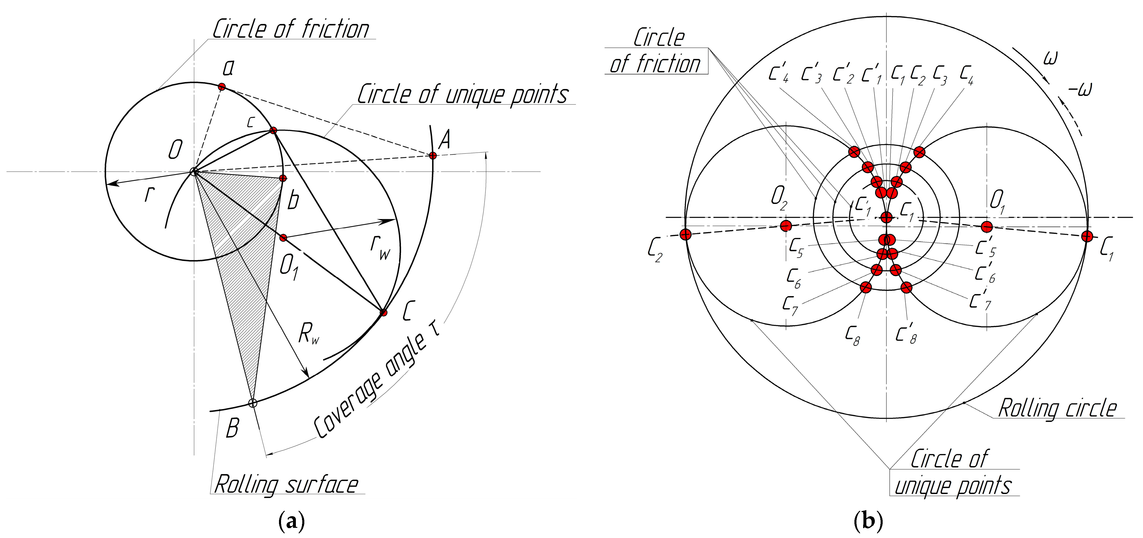
  • Then, the unique points (c0.5; c2; c4; c 0.5 ; c 2 ; c 4 ) as a result of the intersection of friction circles for the initial friction coefficients (φf1 = 0.05; φf2 = 0.28; and φf3 = 0.34) with a circle of unique points described with the center at point O1 and radius rw = 0.25∙Dw are geometrically determined.
  • Furthermore, an arc, O , and marking the intersection points O 1 , O 2 with circles of radius Rw are geometrically drawn from point B with the radius Rw. Then, the centers A 1 and A 2 located on ∪AA0 and formed by the radius AB with the center at point B are drawn. Points O 1 and O 2 determine the position of the center of the wheel relative to the clinodual-worn pad.
  • The next step is to draw arcs with the radii O 1 d and O 2 d from point O to the intersection with the trajectory of kinematic node movement d. The intermediate positions occupied by the kinematic node, d, relative to the center of point O (points D1 and D2 are marked in Figure 9) are determined. This is the result of pad upper-end wear by the amounts of Δb and 2∙Δb.
  • Then, the corresponding points, B1 and B2, on the rolling circle of the wheel are determined when they intersect with arcs of radius Ad drawn from the centers D1 and D2.
  • When the positions of points B1 and B2 are determined, the centers C1 and C2 on the ∪AB braking sector of the clinodual-worn pad are determined. To conduct this, the points on the same rolling circle of the wheel with arcs are marked. Their radii are equal to the chords, which are in the contacts of the arcs ∪BA1/2 and ∪BA2/2. These arcs are drawn from centers B1 and B2, respectively.
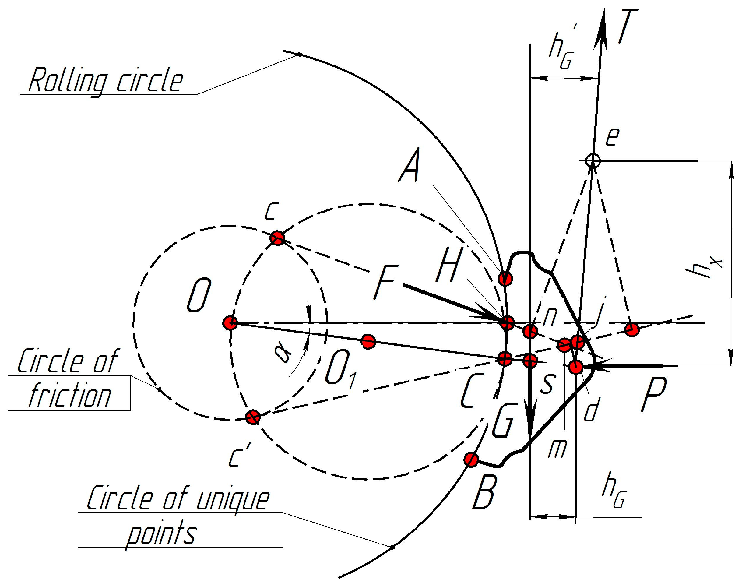
  • The wear of the pads during wheel rotations clockwise and counterclockwise is observed at their intersection points, ∪AB, with lines c4j, c4j1, and c4j2 and c 4 j, c 4 j1, and c 4 j2 for the centers Hb and Ht (the points Hb and Ht are not presented in Figure 9). At the same time, the coordinates of point j are represented by Formula (16) for the variable location of the pendulum suspension of the brake pad, |ed|. These points are not marked in Figure 9 because they will have constantly different coordinates due to the braking process, which is a time function.
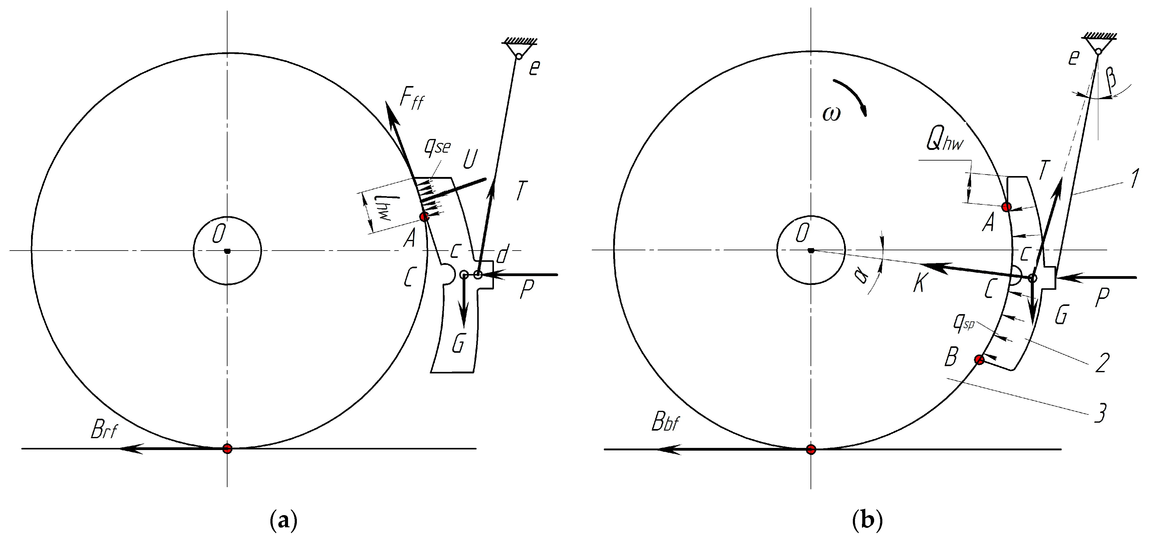
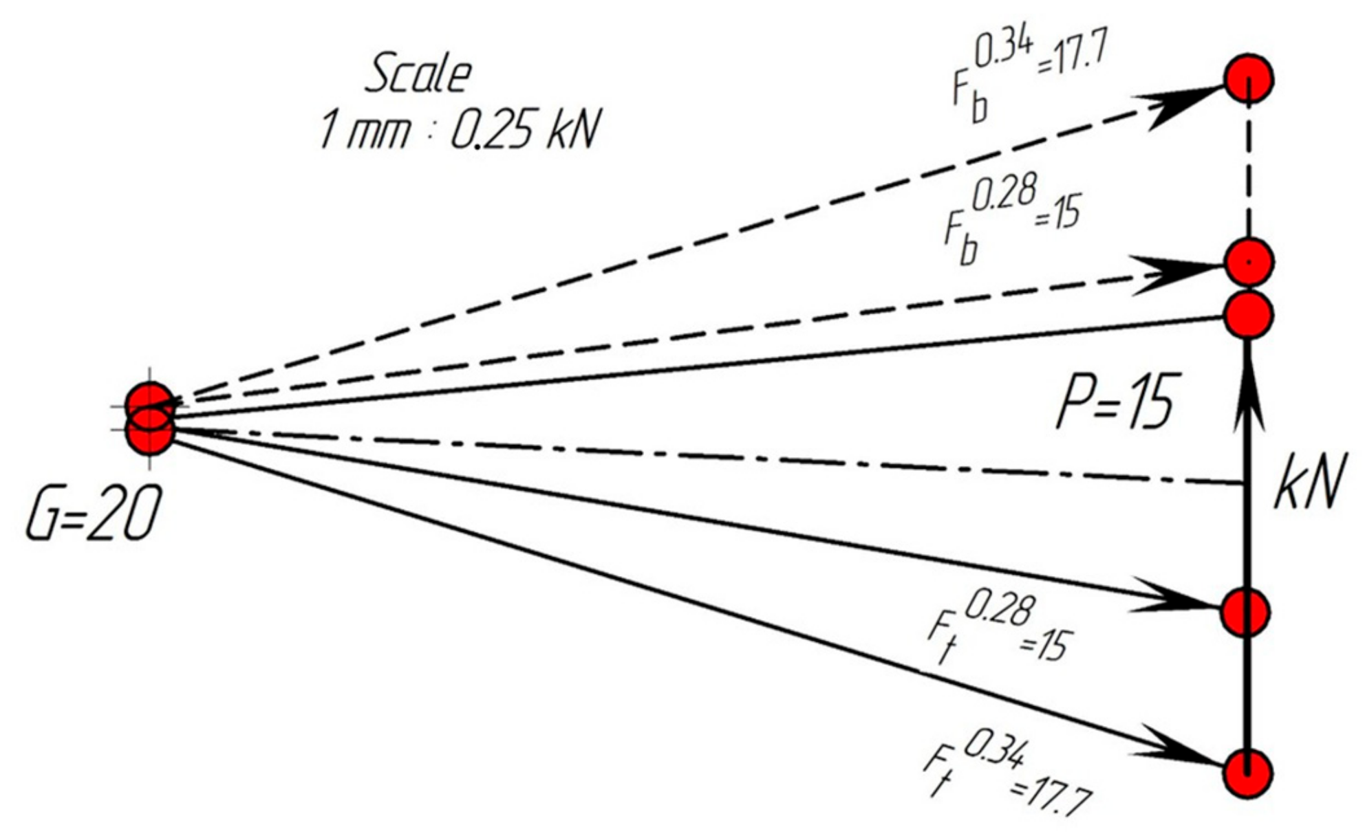
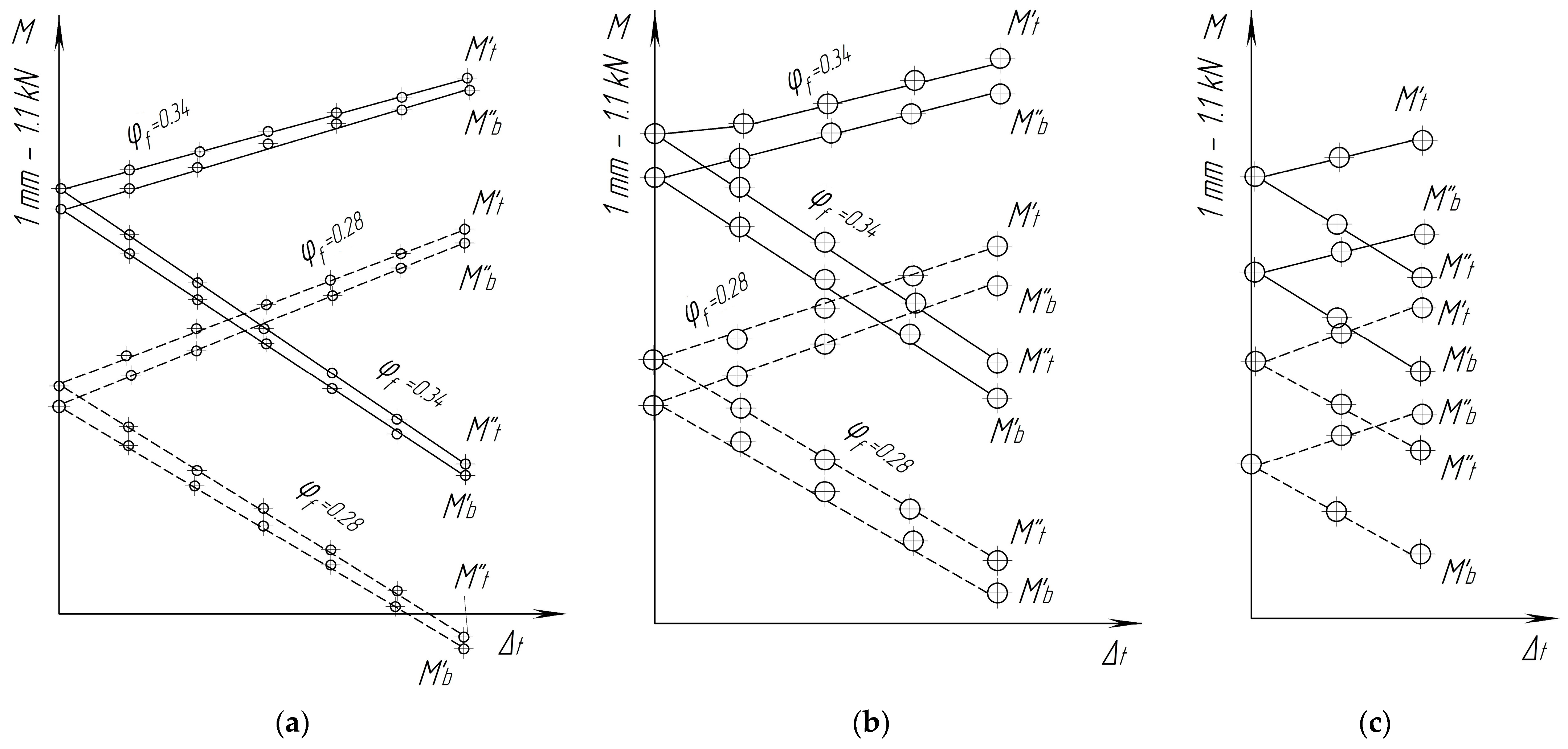
  • Furthermore, the moments Mt and Mb are calculated using Formula (19). The force, F, is determined for each value, Δb, from the force’s polygon (Figure 10). The arms Δt and Δb are determined directly by their measuring from Figure 9. The lengths of the perpendiculars descend from the centers C, C1, and C2 on the line of action of the force.
  • The cycle is repeated for the next value of the friction coefficient according to the initial data up to the last of the available φf.
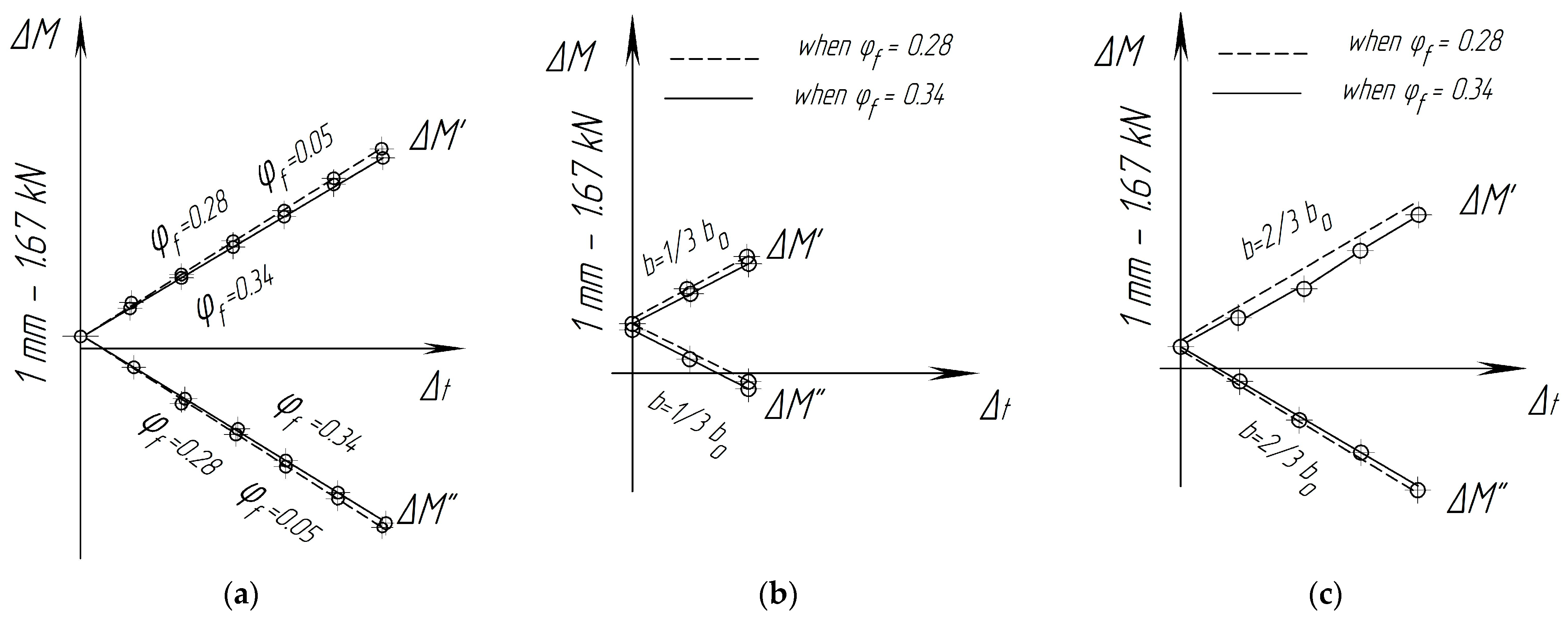
  • At the final stage, the graphoanalytical solution of the problem in the form of dependencies for moments Mt and Mb for two-way wheel movement is obtained together with the various friction coefficients, φf, under the condition of clinodual wear in the upper-pad part.
In addition to the described methodology, a computer program algorithm was developed for the analytical solution of similar problems [50]. Corresponding calculations in the form of control problems were calculated for the new and for the clinodual-worn brake pads with initial thicknesses of 2/3∙b0 and 1/3∙b0, respectively (Figure 11).
It can be seen that, during the movement of railway vehicles (“forward” and “backward”), there is a clinodual wear of the brake pads with the parameters confirmed in operational conditions. In addition, the values of the moments Mt and Mb and, therefore, wear of the pads during the two-way movement of the wheels are different [50].
Thus, the formation of clinodual wear during braking is ultimately due to the excess moment of forces, which is determined by the following formulation:
Δ M = M t M b .
The magnitude and direction of action of excess moments depend on the location of the wear centers Hb and Ht relative to the centers of the contact arc of the pad AB. The results of the calculations are presented in the form of graphs in Figure 11. With the help of this graphical solution, it is possible to determine the dependences for the values of excess moments as functions of the value Δb of one-sided wear of the brake pads acting on the new (Figure 12a) and on the worn (Figure 12b) pads with different coefficients of friction:
Δ M = M t M b , Δ M = M t M b . .
Hence, the graphs of the dependencies Δ M Δ t and Δ M Δ t built using the calculation for the new and for the worn pads in real operating conditions provide a reason to estimate the magnitude and direction of the excess moment.
It can be seen in Figure 12 that the excess moments Δ M and Δ M practically do not depend on the friction coefficient. However, these moments increase with the increase in clinodual pad wear.
In order to eliminate clinodual wear of CBPs in freight wagons, the moment Δ M should equal to zero, i.e.,
M B M N = 0 .
However, this is possible only if the line of symmetry of the CBP passes through the point, j, of the pendulum suspension because only then are the wear centers Hb and Ht located symmetrically to the center, C [10,50].
In our opinion, it is very difficult to achieve the conditions described in Formula (22) for the operating conditions. Indeed, if we assume that, even in a new pad, the point j lies on its axis of symmetry, then, in practice, it should shift from this axis. The first reason for this is that, during the wear of the CBP, point j does not move along the straight line, |Cj|, but along the arc, j j , described from point e (Figure 9). The second reason is that, as the pad wears, the values of G, hG, and h G change. This means that the input parameter is changed in the Formula (17). Therefore, the coordinates of point j change during the operation of the pads. Probably, the clinodual wear of the brake pad cannot be eliminated by choosing the initial position of the hinge point, d, of the new pad.

4. Discussion

This study proposed the use of a force analysis to solve the problem of the clinodual wear of pads, which disintegrate due to the application of the method of the quasi-static analysis of CBPs. At the same time, the feature of the harmful abrasion of the pad at the upper end, which causes clinodual wear, is taken into account. A rational place for mounting the pad was determined, which made it possible to eliminate its abnormal wear, as well as increase the performance of the pads for the entire inter-repair period of operation of the wagon.
The research conducted in this study created the prerequisites for the development of a device for the uniform removal of brake pads from the wheels, which was equipped with 10 wagons in the fleet of freight wagons of the Ukrzaliznytsia Stock Company (Ukraine) [10]. Operational tests of this device are currently underway.
The experimental studies on wagons proved that no damage or wear and tear during operation was detected on the devices. The obtained values of wear and tear of the CBPs in experimental wagons proved that their service life is at least 210,000 km. Therefore, the CBP performance provides the inter-repair period of wagon operation, taking into account the periodic adjustment of the bogies.
As a shortcoming of this study, it can be noted that the authors did not take into account the gaps in the hinge joints of the levers of the brake lever transmission system during theoretical studies.
The advantage of the conducted research in comparison with the analyzed sources is that the authors investigated for the first time the rationality of the location of the hole and suspension of the triangle of the brake lever transmission system of the freight-wagon bogies, model 18-100, depending on the amount of upper harmful abrasion of the pad.
The limitation of this study is the fact that it focused on the design of bogie model 18-100, which has found serial use on railways with a gauge of 1520 mm. In the future, we plan to integrate the obtained methodology into the study of the wear of brake pads and other types of freight-wagon bogies.
The conducted research contributes to the improvement in traffic safety conditions; the reduction in rolling resistance of trains in traction and coasting modes, which leads to the reduction in energy carriers for the traction of trains; the reduction in surface defects of the wheels of wagons and, accordingly, the rails; and the improvement in environmental friendliness [56,57].
Further development of this study will consist of the optimization of the geometric parameters of the brake pad. Moreover, one of the options for the development of this research is to use new materials for the production of pads [58,59], thus ensuring strength indicators and maintainability during manufacture, operation, and repair.

5. Conclusions

1.
The method of quasi-static analysis was applied to determine the harmful wear of the composite brake pads of freight wagons. This method made it possible to carry out a geometrical analysis of the pendulum suspension system of CBPs with clinodual wear and its interaction with the wheel. Moreover, this approach made it possible to establish that the unique point is the point of intersection of the friction circle. The position of the point on the axis of the pendulum suspension makes it possible to determine the mathematical values for the arms of the moments of forces during braking for the upper and lower parts of the CBP.
It was determined that the coverage angle of the brake pad decreased due to its wedge duality. This leads to increasing the specific pressures in the upper part and decreasing the pressures in the lower part. Because of this, the uneven wear of the lower part of the pad increases. This lower part performs the braking mechanism.
2.
The force factors that ensure the quasi-static equilibrium of the articulated elements of the suspended pad during the braking of the freight-wagon bogie were determined, which made it possible to create the prerequisites for solving the problems related to the clinodual wear of CBPs. Based on the performed quasi-static analysis, it was determined that the moments for the upper and lower parts of the CBP depended on many parameters. Excessive values of the moments lead to the formation and increase in the intensive wedge dual wear of pads during the movement of freight wagons. It was established that, due to the clinodual wear of the pad, the braking area of its upper part decreased with the increase in the mileage of wagons, which negatively affected both the braking efficiency of the freight train and the safety of train traffic.
3.
The methodology and procedure for an analytical solution to the problem of the quasi-static balance of forces and moments acting during braking of a wheel with a pad brake in the case of two-way traffic, if identical events occur during braking, were presented. Based on the results of this study, it was established that, to eliminate the clinodual wear of the pads, the excess torque should be equal to zero. A rational place for mounting the block was determined, which made it possible to eliminate its abnormal wear in operational conditions.

Author Contributions

Conceptualization, A.L. and V.R.; methodology, S.P., A.L. and V.R.; software, V.R. and M.B.; validation, S.P., J.G., A.L. and V.R.; formal analysis, A.L., V.R. and J.D.; investigation, S.P., A.L., V.R. and J.D.; resources, A.L., V.R. and J.D.; data curation, A.L., V.R. and M.B.; writing—original draft preparation, A.L., V.R. and J.D.; writing—review and editing, S.P. and J.G.; visualization, V.R.; supervision, S.P. and J.G.; funding acquisition, J.G., A.L. and J.D. All authors have read and agreed to the published version of the manuscript.

Funding

This publication was issued thanks to support from the Cultural and Educational Grant Agency of the Ministry of Education of the Slovak Republic in the project KEGA 031ŽU-4/2023: “Development of key competencies of the graduates of the study program Vehicles and Engines.” This research was also supported by the Slovak Research and Development Agency of the Ministry of Education, Science, Research and Sport of the Slovak Republic in the Educational Grant Agency of the Ministry of Education of the Slovak Republic in the project and VEGA 1/0513/22 “Investigation of the properties of railway brake components in simulated operating conditions on a flywheel brake stand”. “This study was funded by the EU NextGenerationEU through the Recovery and Resilience Plan for Slovakia under project No. 09I03-03-V01-00131.”

Data Availability Statement

Data are contained within the article.

Conflicts of Interest

The authors declare no conflicts of interest.

Nomenclature

aDistance from the hinge, d, of the pendulum suspension to hinge c, a = d + c
bDistance from the hinge, c, to the point of action of force G, b = c
b0Thickness of the new pad, b = b0
BrfForce of resistance to rolling
cCircle of unique points
|cd|Dynamic eccentricity
dKinematic node
DwDiameter of the rolling circle of the wheel in the plane that “cuts” the pad symmetrically, Dw = 2∙Rw
dFForm of distributed discrete forces
Sectoral angle of discrete separation, Qef, from the top, τt, to the bottom, τb, of the working surface of the pad in the sector, τ
eFixed point of the hinge
FOpposing reaction
FffFriction force
GGravitational force generated by the weight of the bogie-brake-system parts
hDistance between the point of concentrated friction force application (point C) and point H
HPoint center of wear of the brake-pad working surface
hGArm of action of the moments
hXArm of action of the moments of the respective forces
KPressure force on the pad
lLength of the pendulum suspension, l = |ed|
l1Distance from point j to point e, l1 = |ej|
l2Distance from point j to the kinematic node at point d, l2 = |jd|
mWidth of a brake pad
MbMoment that causes the formation of a wedge in the lower part of the pad
MffMoment of friction forces
MtMoment that causes the formation of a wedge in the upper part of the pad
PForce that acts on the brake pad from the triangle side during braking
QefWorking (brake) pad area
QшcmArea of harmful abrasion
qseSpecific force
rCircle with radius
RwRadius of the rolling circle
sCenter of gravity
TForce reactions of the pendulum suspension
UForce of pressing the top of the block to the wheel
αAngle between the horizontal axis that passes through the center of the wheel and the middle of the brake pad, C
Angle of coverage of the wheel pad, 2∙α = τ
βSuspension angle
γFriction angle
δShift
ΔcOne-sided brake-pad wear
Δ M Excess moment of forces
Δ v One-side harmful wear
ξDFriction-force-reduction factor due to clinodual pad wear
τAngle of coverage of the pad
φ K Friction-coefficient brake pad
ωRotation of the wheel

References

  1. Panchenko, S.; Gerlici, J.; Vatulia, G.; Lovska, A.; Pavliuchenkov, M.; Kravchenko, K. The Analysis of the Loading and the Strength of the FLAT RACK Removable Module with Viscoelastic Bonds in the Fittings. Appl. Sci. 2023, 13, 79. [Google Scholar] [CrossRef]
  2. Baranovskyi, D.; Muradian, L.; Bulakh, M. The Method of Assessing Traffic Safety in Railway Transport. In Proceedings of the International Scientific Conference and Technology Conference on Earth Science, Vladivostok, Russia, 6–9 October 2020. [Google Scholar] [CrossRef]
  3. Singh, S.; Kumar, R.; Kumar, U. Applying human factor analysis tools to a railway brake and wheel maintenance facility. J. Qual. Maint. Eng. 2015, 21, 89–99. [Google Scholar] [CrossRef]
  4. Zvolenský, P.; Barta, D.; Grenčík, J.; Droździel, P.; Kašiar, Ľ. Improved method of processing the output parameters of the diesel locomotive engine for more efficient maintenance. Eksploat. Niezawodn. 2021, 23, 315–323. [Google Scholar] [CrossRef]
  5. Łukasik, Z.; Kuśmińska-Fijałkowska, A.; Olszańska, S.; Roman, M. Analysis and evaluation of the planning process in a transport company. Sci. J. Silesian Univ. Technol. Ser. Transp. 2022, 115, 35–51. [Google Scholar] [CrossRef]
  6. Lunys, O.; Dailydka, S.; Steišunas, S. Study of freight wagon speed control efficiency at sorting wagons from marshalling humps. In Proceedings of the 20th International Scientific Conference on Transport Means, Juodkrante, Lithuania, 5–7 October 2016. [Google Scholar]
  7. Inagamov, S.; Djabbarov, S.; Abdullaev, B.; Ruzmetov, Y.; Inoyatov, K.; Hurmatov, Y. Study of the friction of the brake shoe of a freight car. In Proceedings of the 5th International Scientific Conference on Construction Mechanics, Hydraulics and Water Resources Engineering, Tashkent, Uzbekistan, 26–28 April 2023. [Google Scholar] [CrossRef]
  8. Budati, S.; Leman, Z.; Sulaiman, M.H.; Azmah Hanim, M.A.; Ghazali, M.J. An investigation into the physical, mechanical, tribology, thermal and durability performance of commercial brake material for rail transportation. Proc. Inst. Mech. Eng. Part J J. Eng. Tribol. 2023, 237, 1620–1631. [Google Scholar] [CrossRef]
  9. Radulović, S.; Milković, D.; Raković, M.; Simić, G.; Kostić, A. Influence of the Head Wind on Determining Braking Performance of Zacns Tank Wagon. Acta Polytech. Hung. 2022, 19, 81–98. [Google Scholar] [CrossRef]
  10. Ukrainian State Academy of Railway Transport. Development of Design and Technological Documentation for the Modernization of Brake Lever Gears of Carriages of Freight Cars: Report on NDKR (Final); No. DR 0111U008972; Ukrainian State Academy of Railway Transport: Kharkiv, Ukraine, 2012; 53p. (In Ukrainian) [Google Scholar]
  11. Panchenko, S.; Gerlici, J.; Vatulia, G.; Lovska, A.; Ravlyuk, V.; Harusinec, J. Studying the load of composite brake pads under high-temperature impact from the rolling surface of wheels. EUREKA Phys. Eng. 2023, 4, 155–167. [Google Scholar] [CrossRef]
  12. Panchenko, S.; Gerlici, J.; Vatulia, G.; Lovska, A.; Ravlyuk, V.; Rybin, A. Method for determining the factor of dual wedge-shaped wear of composite brake pads for freight wagons. Commun. Sci. Lett. Univ. Žilina 2023, 26, B31–B40. [Google Scholar] [CrossRef]
  13. Gerlici, J.; Lack, T.; Harusinec, J. Development of test stand prototype for rail vehicles brake components testing. Commun. Sci. Lett. Univ. Žilina 2014, 16, 27–32. [Google Scholar] [CrossRef]
  14. Bosov, A.A.; Mjamlin, C.V.; Panasenko, V.Y.; Klimenko, I.V. Ways to Improve the Design of a Freight Car Bogie; Visnik of the Dnipropetrovsk National University of Railway Transport named after V. Lazaryan: Dnipropetrovsk, Ukraine, 2009; Volume 2, pp. 27–32. (In Russian) [Google Scholar]
  15. Tuluzyn, S.V.; Gorsky, D.V. Evaluation of the performance of the brake lever transmission of a freight car trolley at various stages of pad and wheel wear. VNIIZHT Bull. 2015, 38–44. (In Russian) [Google Scholar]
  16. Karpychev, V.A.; Nikitin, G.B.; Andreev, P.A. On the issue of assessing and monitoring the brake pressure of the pads on the wheels depending on the positions of the levers when adjusting the lever transmission of the trolley 18–100. VNIIZHT Bull. 2013, 43–48. (In Russian). Available online: https://www.elibrary.ru/item.asp?id=23237106 (accessed on 20 January 2024).
  17. Smolyaninov, A.V.; Smolyaninov, P.V. Dimensional calculations of the brake lever transmission of a freight car as a method for justifying ways to improve the quality of repairs. Sci. Tech. Mag. Izvestia Transsib. 2012, pp. 27–36. (In Russian). Available online: https://el.omgups.ru/preview/30448 (accessed on 20 January 2024).
  18. Muradian, L.A.; Shaposhnik, V.Y.; Winstroth, B.U.; Mukovoz, S.P. Testing of promising brake pads on the railways of Ukraine. Lokomot. Inform. 2015, 20–22. Available online: https://crust.ust.edu.ua/server/api/core/bitstreams/13245681-5c59-44da-80c7-c13cdda00eb2/content (accessed on 20 January 2024).
  19. Sawczuk, W.; Merkisz-Guranowska, A. Assessment of disc brake vibration in rail vehicle operation on the basis of brake stand. Eksploat. Niezawodn. 2021, 23, 221–230. [Google Scholar] [CrossRef]
  20. Bosso, N.; Gugliotta, A.; Magelli, M.; Oresta, I.F.; Zampieri, N. Study of wheel-rail adhesion during braking maneuvers. Procedia Struct. Integr. 2019, 24, 680–691. [Google Scholar] [CrossRef]
  21. Somà, A.; Aimar, M.; Zampieri, N. Simulation of the thermal behavior of cast iron brake block during braking maneuvers. Appl. Sci. 2021, 11, 5010. [Google Scholar] [CrossRef]
  22. Radzikhovsky, A.A.; Omelyanenko, I.A.; Timoshina, L.A. A systematic approach to the design of bogies for freight cars with increased axial loads. Wagon Park 2008, 8, 10–16. (In Russian) [Google Scholar]
  23. Blokhin, E.P.; Alpysbaev, K.T.; Panasenko, V.Y.; Garkavi, N.Y.; Klimenko, I.V.; Granovsky, R.B.; Fedorov, E.F. ZK1 bogies of gondola cars built in the PRC. Wagon Park 2012, 9, 12–14. [Google Scholar]
  24. Turutin, I.V.; Rudakova, E.A. Design of Bogies Models 18-9889 and 18-9890 for Innovative Four- and Six-Axle Freight Cars. 2013, pp. 10–12. (In Russian). Available online: https://cyberleninka.ru/article/n/konstruktsiya-telezhek-modeley-18-9889-i-18-9890-dlya-innovatsionnyh-chetyrehi-shestiosnyh-gruzovyh-vagonov/viewer (accessed on 20 January 2024).
  25. Wu, Q.; Cole, C.; Spiryagin, M.; Chang, C.; Wei, W.; Ursulyak, L.; Shvets, A.; Murtaza, M.A.; Mirza, I.M.; Zhelieznov, K.; et al. Freight train air brake models. Int. J. Rail Transp. 2023, 11, 1–49. [Google Scholar] [CrossRef]
  26. Wu, Q.; Magelli, M.; Zampieri, N.; Bernal, E. Adding a brake shoe temperature model into freight train longitudinal braking dynamics simulations. Proc. Inst. Mech. Eng. Part F J. Rail Rapid Transit. 2023, 237, 631–641. [Google Scholar] [CrossRef]
  27. Zhang, K.; Liu, P.; Cao, Y.; Yan, Y. Curving Performance of Heavy-Haul Freight Wagons under Asymmetric Brake Shoe Pressures. In Proceedings of the 13th Asia Pacific Transportation Development Conference Resilience and Sustainable Transportation Systems, Shanghai, China, 27–30 May 2020. [Google Scholar] [CrossRef]
  28. Zhang, J.; Li, Y.-H.; Fang, J.; Zhao, W.-Z. Research on squeal noise of tread brake system in rail freight vehicle. In Proceedings of the 2nd International Conference on Design, Materials and Manufacturing, Beijing, China, 23–25 June 2017. [Google Scholar] [CrossRef]
  29. Koch, S.; Koppen, E.; Grabner, N.; von Wagner, U. On the influence of multiple equilibrium positions on brake noise. Facta Univ. Ser. Mech. Eng. 2021, 19, 613–632. [Google Scholar] [CrossRef]
  30. Xiao, F.; Chen, X. Wear analysis of the synthetic brake shoe with high friction of the freight train under harsh conditions. J. Beijing Jiaotong Univ. 2014, 38, 20–25. [Google Scholar]
  31. Li, N.; Wei, Z.; Cao, Z. Automatic fault recognition for Brake-Shoe-Key losing of freight train. Optik 2015, 126, 4735–4742. [Google Scholar] [CrossRef]
  32. Zhu, Q.; Vhen, G.X.; Wu, B.W.; Kang, X. Effect of the Material Parameter and Shape of Brake Pads on Friction-Induced Disc Brake Squeal of a Railway Vehicle. Tribol. Trans. 2021, 64, 744–752. [Google Scholar] [CrossRef]
  33. Radzikhovsky, A.A.; Omelyanenko, I.A.; Timoshina, L.A. Brake pad removal device. Wagon Park 2009, 11–12, 18–22. (In Russian) [Google Scholar]
  34. Cruceanu, C. Brakes for Railway Vehicles; Matrix Rom Publishing House: Bucharest, Romania, 2007. [Google Scholar]
  35. Cruceanu, C.; Oprea, R.; Spiroiu, M.; Craciun, C.; Arsene, S. Computer Aided Study Regarding the Influence of Filling Characteristics on the Longitudinal Reaction within the Body of a Braked Train. In Proceedings of the 13th WSEAS International Conference on Computers, Rods, Greece, 22–24 July 2009. [Google Scholar]
  36. Bucur, F.; Socalici, A.; Berghian, A.B.; Baneasa, C.B.; Pascu, L. The tribology of composite materials used for manufacturing brake shoes. Mater. Plast. 2022, 59, 13–20. [Google Scholar] [CrossRef]
  37. Cruceanu, C.; Craciun, C. Aspects regarding the braking capacity of composite brake shoes for railway vehicles. Mater. Plast. 2019, 56, 18–21. [Google Scholar] [CrossRef]
  38. Kiss, I.; Cioata, V.; Alexa, V.; Ratiu, S. Investigations on the phosphorous cast iron destined for brake shoes manufacturing. Appl. Eng. Lett. 2016, 1, 61–66. [Google Scholar]
  39. Kiss, I. The chemical composition of phosphorous cast irons behavior in the manufacturing of brake shoes meant for the rolling stock. Acta Tech. Corviniensis Bull. Eng. 2016, 9, 77–84. [Google Scholar]
  40. Nam, J.; Kang, J. Semi-analytical approach for brake squeal of a rail pad. J. Mech. Sci. Technol. 2020, 34, 3147–3153. [Google Scholar] [CrossRef]
  41. Bosso, N.; Cantone, L.; Falcitelli, G.; Gjini, R.; Magelli, M.; Nigro, F.M.; Ossola, E.; Zampieri, N. Simulation of the thermo-mechanical behaviour of tread braked railway wheels by means of a 2D finite element model. Tribol. Int. 2023, 178, 1–12. [Google Scholar] [CrossRef]
  42. Cruceanu, C. Train Braking. In Reliability and Safety in Railway; Perpinya, X., Ed.; IntechOpen: London, UK, 2012; pp. 29–74. [Google Scholar]
  43. Zhang, Y.; Chen, Y.; He, R.; Shen, B. Investigation of tribological properties of brake shoe materials-phosphorous cast irons with different graphite morphologies. Wear 1993, 166, 179–186. [Google Scholar] [CrossRef]
  44. Pascu, L.V. Research on Improving the Quality of Brake Shoes Intended for Rolling Stock. Ph.D. Thesis, University Politehnica Timisoara, Timisoara, Romania, 2015. (In Romanian). [Google Scholar]
  45. TST–TSV–TSL–0015; Instructions for Operating Rolling Stock Brakes on Ukrainian Railways. CSREA Press: Kyiv, Ukraine, 2004; 146p.
  46. STP 04-028; Freight Cars. Braking Equipment. Ukrainian Railway: Kyiv, Ukraine, 2020; 117p. (In Ukrainian)
  47. CV–CL–0013; Instructions for the Repair of Braking Equipment of Wagons. Ukrainian Railway: Kyiv, Ukraine, 2004; 160p. (In Ukrainian)
  48. TU U 6-05495978.017-2001; Composite Brake Pads with a Mesh-Wire Frame for Railway Freight Cars. OJSC “Tribo”: Lviv, Ukraine, 2001; 27p. (In Ukrainian)
  49. Babaev, A.M.; Dmytriev, D.V. Principle of Action, Calculations and Basics of Operation of Railway Rolling Stock Brakes: Study Guide; DETUT: Kyiv, Ukraine, 2007; 176p. (In Ukrainian) [Google Scholar]
  50. Ravlyuk, V.; Ravlyuk, M.; Hrebeniuk, V.; Bondarenko, V. Research of the calculation scheme for the brake lever transmission and construction of the load model for the brake pads of freight cars. In Proceedings of the 8th International Scientific Conference Reliability and Durability of Railway Transport Engineering Structures and Buildings TransBud 2019, Kharkiv, Ukraine, 20–22 November 2019. [Google Scholar] [CrossRef]
  51. Ravlyuk, V.G.; Afanasenko, I.M. Research for a Course Project with Methodical Additions from the Discipline “Automatic Care and Safety of the Traffic”: Methodical Additions; UkrDAZT: Kharkiv, Ukraine, 2012; 70p. (In Ukrainian) [Google Scholar]
  52. Shchepetilnikov, V.A. On the issue of uneven wear of pads. Issues of operation and repair of rolling stock. Collect. Sci. Works 1955, 82, 366–381. [Google Scholar]
  53. Karvatsky, B.L. General Theory of Automatic Brakes; Transzheldorizdat: Moscow, Russia, 1947; 300p. (In Russian) [Google Scholar]
  54. Sarma, K.V.S.; Vardhan, R.V. Multivariate Statistics Made Simple. A Practical Approach: Manual; Chapman and Hall/CRC: New York, NY, USA, 2018; 258p. [Google Scholar]
  55. Kamkina, L.V.; Nadtochii, A.A.; Grishin, A.M.; Stogniy, Y.D. Fundamentals of Scientific Research: A Study Guide; NMetAU: Dnipropetrovsk, Ukraine, 2013; 89p. (In Ukrainian) [Google Scholar]
  56. Kagramanian, A.; Aulin, D.; Trubchaninova, K.; Caban, J.; Voronin, A.; Basov, A. Perspectives of multifunctional integrated suburban-urban rail transport development. Sci. J. Silesian Univ. Technol. Ser. Transp. 2023, 120, 105–115. [Google Scholar] [CrossRef]
  57. Drozd, K.; Nieczym, A. Modeling and exploitation load tests of the suspended route slings caused by passage of the locomotive at various speed along mining excavation. Adv. Sci. Technol. Res. J. 2022, 16, 266–281. [Google Scholar] [CrossRef]
  58. Walczak, M.; Caban, J. Tribological characteristics of polymer materials used for slide bearings. Open Eng. 2021, 11, 624–629. [Google Scholar] [CrossRef]
  59. Mikhailov, M.; Semenov, S.; Sapronova, S.; Tkachenko, V. On the issue of wheel flange sliding along the rail. In Proceedings of the 11th Transbaltica International Scientific Conference 2019, Vilnius, Lithuania, 2–3 May 2019. [Google Scholar] [CrossRef]
Figure 1. Clinodual wear of a CBP: (a) pads removed from a wagon with large remaining working mass; (b) overtime clearances between the “pad–wheel” tribotechnical pair.
Symmetry 16 00346 g001
Figure 2. A model of a brake lever transmission system of a two-axle wagon with brake pads: 1, 2—vertical lever; 3—triangle; 4—brake pad; 5—pad holder; 6—pendulum suspension; 7—delimiter of clearance; 8—spacer triangle; and 9—bracket with a lock (a device for uniform pad wear).
Symmetry 16 00346 g002
Figure 3. A scheme of the formation of clinodual frictional wear of the brake pad: (a) reproduction of the initial center of abrasion of the brake-pad upper end during movement without braking; (b) braking with a pad brake with the development of its clinodual frictional wear.
Symmetry 16 00346 g003
Figure 4. A 3D model of the CBP with clinodual wear: 1—harmfully worn pad surface; 2—a line of separation of planes; 3—a plane of brake (working)-pad wear; 4—a block body; 5—the result of brake wear; and 6—the result of harmful wear.
Symmetry 16 00346 g004
Figure 5. A scheme of the reaction formation of the wheel, F = K = P∙cosα, as the sum of the forces, dF, acting on the sections, dQ, of the working surface of the CBP, Qef.
Symmetry 16 00346 g005
Figure 6. A scheme of the construction of unique points: (a) circles; (b) front and rear brake pads in the direction of movement.
Symmetry 16 00346 g006
Figure 7. Forces acting on the brake pad and a pendulum suspension.
Symmetry 16 00346 g007
Figure 8. A scheme of the interaction of the CBP with the wheel during braking: (a) coincidence of the center of wear with the center of the contact arc of the pad; (b) determination of the excess moment for the deviation of the center of wear from the center of the pad.
Symmetry 16 00346 g008
Figure 9. Determining the wear centers of the CBP during a two-direction operation.
Symmetry 16 00346 g009
Figure 10. The polygon of the forces acting on the CBP.
Symmetry 16 00346 g010
Figure 11. The dependence of the moments Mt and Mb on the Δv for a symmetrical pad: (a) when b = b0; (b) when b = 2/3∙b0; and (c) when b = 1/3∙b0.
Symmetry 16 00346 g011
Figure 12. The dependence values of the excess moments Δ M Δ t and Δ M Δ t on the parameter, Δb, for a symmetrical pad: (a) when b = b0; (b) when b = 2/3∙b0; and (c) when b = 1/3∙b0.
Symmetry 16 00346 g012
Disclaimer/Publisher’s Note: The statements, opinions and data contained in all publications are solely those of the individual author(s) and contributor(s) and not of MDPI and/or the editor(s). MDPI and/or the editor(s) disclaim responsibility for any injury to people or property resulting from any ideas, methods, instructions or products referred to in the content.

