Article

Computational Design of an In-Line Coaxial-to-Circular Waveguide Adapter with More Than an Octave Bandwidth

School of Electric and Computer Engineering, Chungbuk National University, Cheongju 28644, Republic of Korea
*
Authors to whom correspondence should be addressed.
Symmetry 2024, 16(3), 304; https://doi.org/10.3390/sym16030304
Submission received: 26 December 2023 / Revised: 14 February 2024 / Accepted: 1 March 2024 / Published: 5 March 2024

Abstract

:
This paper presents a computer-simulation-based design of an in-line, coaxial-to-circular waveguide adapter for converting the coaxial transverse electromagnetic (TEM) mode to the circular waveguide TE11 mode over more than a one-octave bandwidth. The proposed adapter consists of a coaxial-to-rectangular waveguide transformer employing a stepped-ridge converter and a rectangular-to-circular waveguide transformer employing a curved transition. The proposed adapter has been optimized using a commercial simulation tool. The dimensions of the designed adapter are given so that it can be verified by anyone who is interested. The designed adapter operates from 8.00 GHz to 22.95 GHz (2.87:1 bandwidth) with a reflection coefficient of less than −20 dB and a higher-order mode level of less than −25.0 dB.

1. Introduction

Circular waveguides are widely used in high-frequency signal transmission as well as in various microwave components, including rotary joints [1], high-power microwave devices [2], radiating elements [3,4,5,6], measurement fixtures [7] and power transmission using the low-loss TE21 mode [8]. In all these applications, it is often necessary to launch a signal from a coaxial cable to a circular waveguide for which a high-performance adapter is required. In many applications, it is advantageous for an adapter to work with as large a bandwidth as possible.
Coaxial-to-circular waveguide adapters (CCWAs) have been employed in a right-angle form for a prime-focus reflector feed [3], a conical horn [4], a double-ridge horn [5] and a quad-ridge horn [6]. An in-line CCWA has been used to convert the coaxial TEM mode to the circular TM01 mode in the measurement of a liquid material [7] and in a high-power microwave application [8]. In these applications, a broadband coaxial-to-circular waveguide transition, with a reflection coefficient of less than −20 dB would be very helpful.
In a coaxial-to-metallic waveguide adapter, the conversion between the coaxial TEM mode to the fundamental waveguide mode has been realized using a simple cylindrical probe [9], a disc probe [10], a conical probe [11] and a stepped-ridge converter [12,13]. In most of the existing works on CCWAs, right-angle structures have been employed, where the coaxial cable axis is perpendicular to the circular waveguide axis, as indicated by the studies of [14,15,16]. Bang and Ahn presented a wideband, right-angle CCWA that operates from 1.04 to 2.53 times the TE11-mode cutoff frequency of the circular waveguide, with a reflection coefficient of less than −20 dB [11]. Schönfield, Tsai and Chu presented a right-angle CCWA with double ridges in a circular waveguide [16]. Their adapter operates from 0.83 GHz to 2.8 GHz, with a reflection coefficient of less than 0.3 (−10 dB).
For some applications, it is advantageous to use an in-line adapter instead of a right-angle one. In-line CCWAs have mostly been studied for TEM-TM01 mode conversion [17,18]. A thorough literature survey reveals that only two previous works [19,20] have been published on in-line TEM-TE11 mode converters with broadband performance. It is also important to point out that no commercial in-line CCWA product is available at the time of writing.
Tribak and co-workers designed an in-line CCWA as a part of their circular waveguide TM01-TE11 mode converter [19]. Their design employs a coaxial-to-rectangular waveguide transition and a rectangular-to-circular waveguide transition. Their adapter converts the circular waveguide TM01 mode to the circular waveguide TE11 mode at 9.25–16.26 GHz. Yun and co-workers used a printed dipole to realize an in-line CCWA operating at 13.6–17.9 GHz [20].
The purpose and goal of this paper is to design a broadband, in-line adapter connecting a coaxial cable to a circular waveguide. Our work is built upon the work in [11], where a single rectangular waveguide section was employed between a coaxial cable and a circular waveguide for improved broadband performance. This paper proposes an advancement in the related method by employing three rectangular waveguide sections and a smooth spline-shaped transition between the rectangular and circular waveguides to ensure the lower operating frequency limit approaches the cutoff frequency of the circular waveguide’s TE11 mode. The upper end of the operating frequency is extended to its maximum by making the structure as symmetrical as possible so that the higher-order modes are suppressed as much as possible. The end result is an in-line, coaxial-to-circular waveguide adapter operating from 8.00 GHz to 22.95 GHz (a ratio bandwidth of 2.87 or a 96.6% bandwidth). To the best of our knowledge, there is no published work on in-line, coaxial-to-circular waveguide adapters having such a wide bandwidth. CST Studio SuiteTM V2023 was employed in the design of the proposed adapter.
The remainder of this paper is organized as follows. Section 2 describes the design methodology of the adapter that has been adopted in this paper. Section 3 presents a simulation-based design of the proposed adapter. Section 4 contains an interpretation of the design results. Section 5 presents a discussion of the design results. Finally, the conclusion of this paper is presented in Section 6.

2. Adapter Design Methodology

Our goal in this paper is to design an in-line, coaxial-to-circular waveguide adapter operating over more than a one-octave bandwidth. Direct probe-feeding of a circular waveguide does not yield broadband performance. Thus, this paper adopts the approach of Bang and Ahn [11]. First, a coaxial probe excites a rectangular waveguide, which is then transformed to a circular guide using a linear taper.
Figure 1 shows the structure of the proposed adapter. It consists of a circular waveguide W; a circular-to-rectangular waveguide transformer T; the first (R1), second (R2) and third (R3) rectangular waveguides; a four-step ridge converter S; a coaxial probe P passing through a hole H in the back short B; an impedance-matching cavity M; and a coaxial cable C.
The coaxial probe P excites the dominant TE10 mode in the third waveguide R3 via a four-step converter S. The impedance matching between the coaxial cable C and the third rectangular waveguide R3 is predominantly facilitated by the stepped-ridge converter S. The reflection coefficient is reduced to less than −20 dB by adjusting the dimensions of the matching cavity M and the coaxial probe hole H in the waveguide back short B as well as that of the stepped-ridge transformer. Three rectangular waveguide sections, R1, R2 and R3, are employed to extend the operating frequency range of the adapter. The first rectangular waveguide R1 is smoothly transformed to the output circular waveguide W using the spline surface geometry designed in CST Studio SuiteTM V2023.
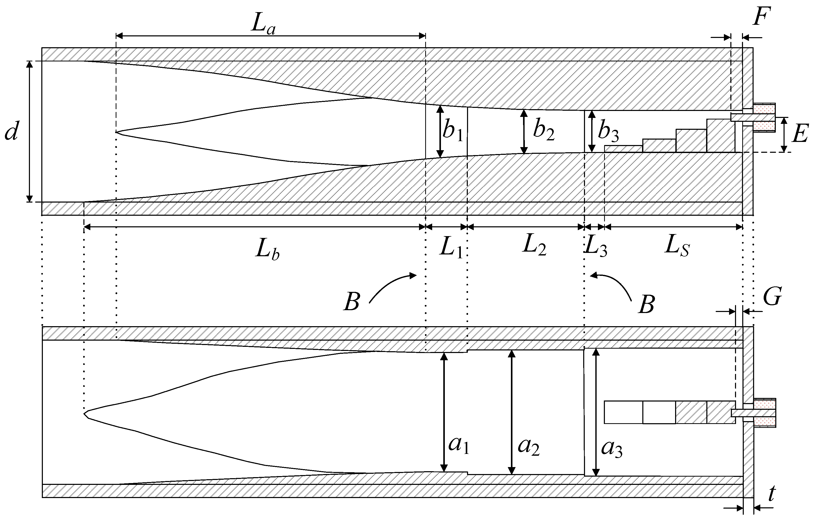
Figure 2 shows the dimensional parameters of the proposed adapter. Figure 2 is drawn to scale, which helps in understanding the design concept. The design of the adapter starts with determining the rough dimensions of the coaxial cable, the rectangular waveguide and the circular waveguide.
For the coaxial cable, a probe of a standard connector is employed, with the diameters of center and outer conductors being 2a and 2b. In a coaxial cable, the fundamental mode is the TEM mode with a cutoff frequency of zero and the next three higher-order modes are the TE11, TE21 and TE31 modes, and their cutoff frequencies are given by the following equations [21]:
f C , TEM = 0
f C , TE 11 = c 1.878 ( π / 2 ) ( a + b ) ε r
f C , TE 21 = c 1.032 ( π / 2 ) ( a + b ) ε r
where c is the speed of the light in vacuum and εr is the dielectric constant of the material filling the coaxial cable. Table 1 lists cutoff frequencies in the SMA connector employed in the proposed transition, where 2a = 1.27 mm, 2b = 4.11 mm and εr = 2.08. The first higher-order TE11 mode is cut off at 26.27 GHz and the second TE21 mode is cut off at 48.09 GHz.
In an air-filled rectangular waveguide, the cutoff frequency of the TEmn modes with a broad wall width of a and narrow wall height of b is given by the following equation:
f R , TE m n = c 2 ( m a ) 2 + ( n b ) 2
The dominant mode in a rectangular waveguide is the TE10 mode, with the cutoff frequency given by
f R , TE 10 = c 2 a
In a rectangular waveguide energized by a coaxial probe, the probe can be placed at the center of the waveguide’s broad wall but not at the center of the waveguide’s narrow wall. In this case, the low-order modes that can be easily excited are the TE11 and TE30 modes. The antisymmetric TE20 mode has a zero field at the center of its broad wall and is not excited by a symmetrically placed coaxial probe. For a waveguide with a width-to-height ratio of 2, the cutoff frequencies of the TE11 and TE30 modes are 2.24 and 3.00 times the TE10 dominant mode’s cutoff frequency. To maximize the bandwidth of the transition, it is necessary to reduce the narrow wall’s height so that the TE11 mode is cut off at the same frequency as the TE30 mode in the waveguide R3.
In designing the rectangular waveguides R1, R2 and R3, the broad wall width a1 of the waveguide R1 is determined first. The broad wall width a3 of the waveguide R3 is made about 5 percent larger than a1 so that the adapter’s lower operating frequency limit is as close as possible to the TE10-mode’s cutoff frequency of the waveguide R1. The waveguide section R2 is used for impedance matching between R1 and R3.
For the conversion between the coaxial TEM mode and the rectangular TE10 mode, a stepped-ridge transformer is employed. Existing structures for TEM-TE10 mode conversion include an L probe [22], a stepped L probe [23], a continuously tapered ridge transformer [24] and a stepped-ridge transformer [25,26,27,28,29,30,31,32,33,34]. A survey of the literature reveals that the stepped-ridge transformer is a preferred geometry for broadband transitions, which has also been adopted in this work.
The diameter d of the circular waveguide W is chosen such that the circular TE11 mode is cut off at the same frequency as the TE10 mode of the rectangular waveguide R1. When a circular waveguide is excited by the TE10 mode of a rectangular waveguide through a smooth transition, such a circular waveguide TE mode is easily excited as the one whose electric field is symmetric in the H plane and non-zero at the center of the waveguide cross-section. The circular waveguide modes compatible with the rectangular TE10 mode include the fundamental TE11 mode and higher-order TM11, TE12 and TM12 modes, whose cutoff frequencies are 2.08, 2.90 and 3.81 times the TE11-mode cutoff frequency, respectively. The cutoff frequencies of these modes are given by the following equations [21]:
f W , TE 11 = c 1.84118 π d ε r
f W , TM 11 = c 3.83171 π d ε r
f W , TE 12 = c 5.3315 π d ε r
Table 1 shows the cutoff frequencies of the first three modes including the dominant mode in the coaxial cable C; three rectangular waveguides R1, R2, R3; and the circular waveguide W in the proposed adapter, whose dimensions are given in the next section. From Table 1, one can see that the adapter’s operating frequency can be limited by the onset of the TM11 mode in the circular waveguide and the TE11 mode in the rectangular waveguide. With a careful design of the structure, one can suppress the level of higher-order modes to less than −25 dB relative to the dominant mode as will be shown later. Figure 3, Figure 4 and Figure 5 show the electric fields at 50 GHz of the modes listed in Table 1 on the cross-section of the coaxial cable C, the rectangular waveguide R3 and the circular waveguide W, respectively. The frequency of analysis is set to 50 GHz to ensure all the modes in Table 1 are above the cutoff.
Finally, for the design of the transition from the rectangular waveguide R1 to the circular waveguide W, a smooth spline surface is employed, which is supported by the simulation tool. Compared with a flat surface or a linear transition, the reflection coefficient is lower with a spline taper. The E-plane taper or the taper in the rectangular waveguide’s narrow wall starts from the middle of the waveguide R2, while the H-plane taper or the taper in the rectangular waveguide’s broad wall starts at the end of the waveguide R2. Due to different transformation ratios in the E- and H-plane cross-sections of the circular and rectangular waveguides, the E-plane taper length Lb is larger than the H-plane taper length La, as shown in Figure 2. The following section presents a simulation-based design of the adapter based on the design methodology presented above.

3. Simulation-Based Design of the Adapter

This section presents a simulation-based design of the proposed adapter. The coaxial-to-rectangular waveguide transformer and the rectangular-to-circular waveguide transformer are designed separately and then combined. The combined structure is optimized to achieve low reflection over a wide frequency range.
The adapter’s dimensional parameters, shown in Figure 2, are optimized using the simulation tool. In designing the coaxial-to-rectangular waveguide transformer, the length, height and thickness of the stepped-ridge converter S, the dimensions of the matching cavity M and the diameter and length of the probe hole H have been optimized using CST Studio SuiteTM V2023. The lengths L1, L2, L3; widths a1, a2, a3; and heights b1, b2, b3 of the waveguides R1, R2 and R3, respectively, have also been optimized. For the rectangular-to-circular waveguide transformer T, this paper has applied a smooth spline taper with its length La and Lb set as control parameters. La and Lb are the length of the taper from the rectangular waveguide’s broad (starting from A and B) and narrow walls to the circular waveguide, respectively. The taper shape is of the spline type provided by CST Studio SuiteTM V2023 with smoothness control applied.
Table 2 shows the final dimensions of an optimized adapter. For the coaxial port, an SMA connector is used. With the dimensions given in Table 2, the cutoff frequencies of the fundamental mode and the excitable higher-order modes are shown in Table 1. These values are of fundamental importance in the design of a broadband adapter. It is important to sufficiently suppress the excitation of the higher-order modes (TM11 and TE12 modes in the circular waveguide; TE11, TM11 and TE30 modes in the rectangular waveguide).
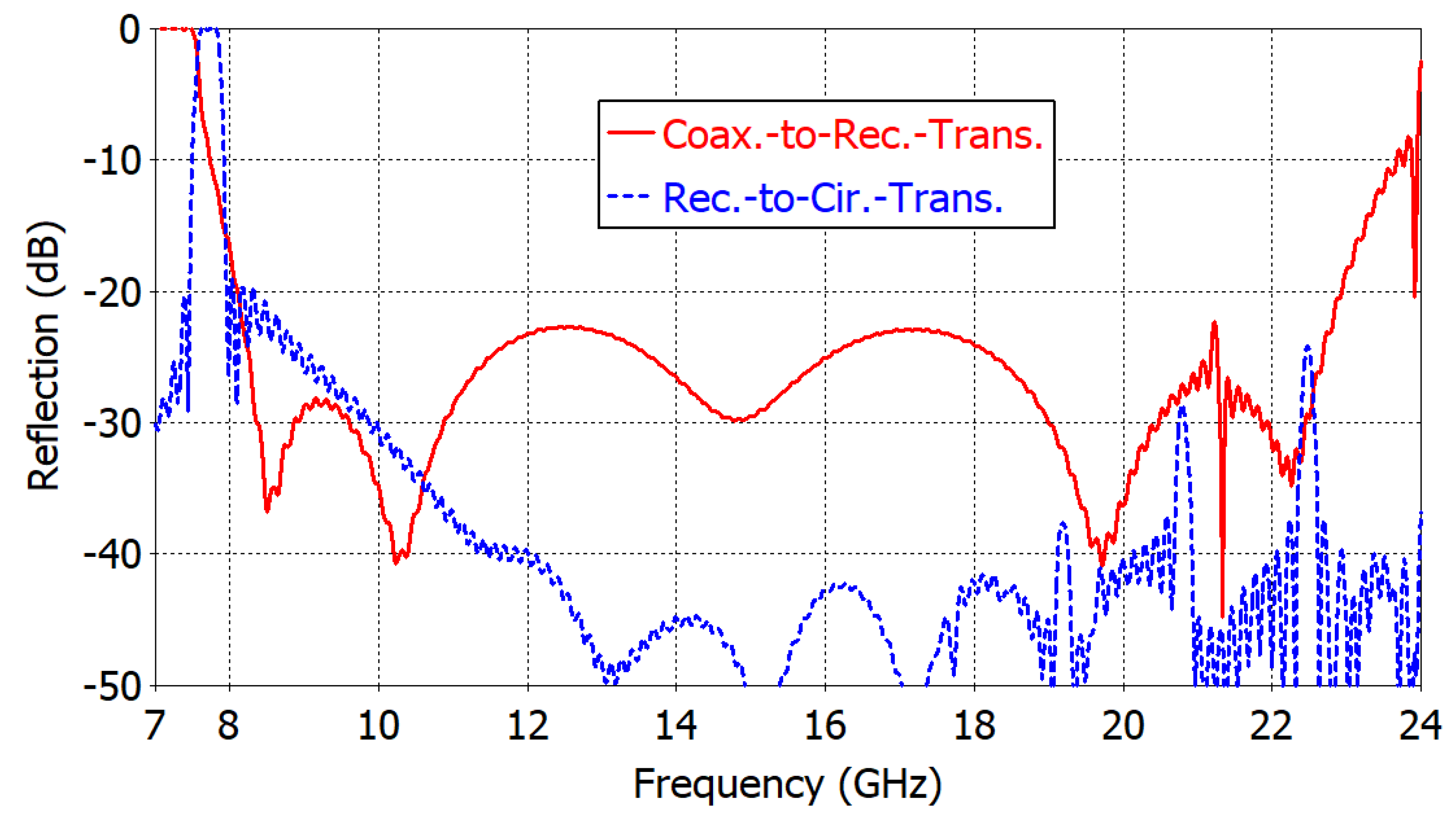
Figure 6 shows the reflection coefficient from the time-domain analysis of the coaxial-to-rectangular waveguide transformer and the rectangular-to-circular waveguide transformer. The lengths La and Lb of the rectangular-to-circular waveguide transformer are made sufficiently large so that the reflection coefficient is less than −20 dB at 8–24 GHz. Local peaks due to higher-order mode excitation occur at 19.18, 20.87 and 22.46 GHz. The coaxial-to-rectangular transformer is optimized for reflections < −20 dB at a 8–23 GHz frequency range. A local peak is observed at 21.25 GHz. The reflection coefficient of the final combined structure will closely follow that of the coaxial-to-rectangular waveguide transformer.
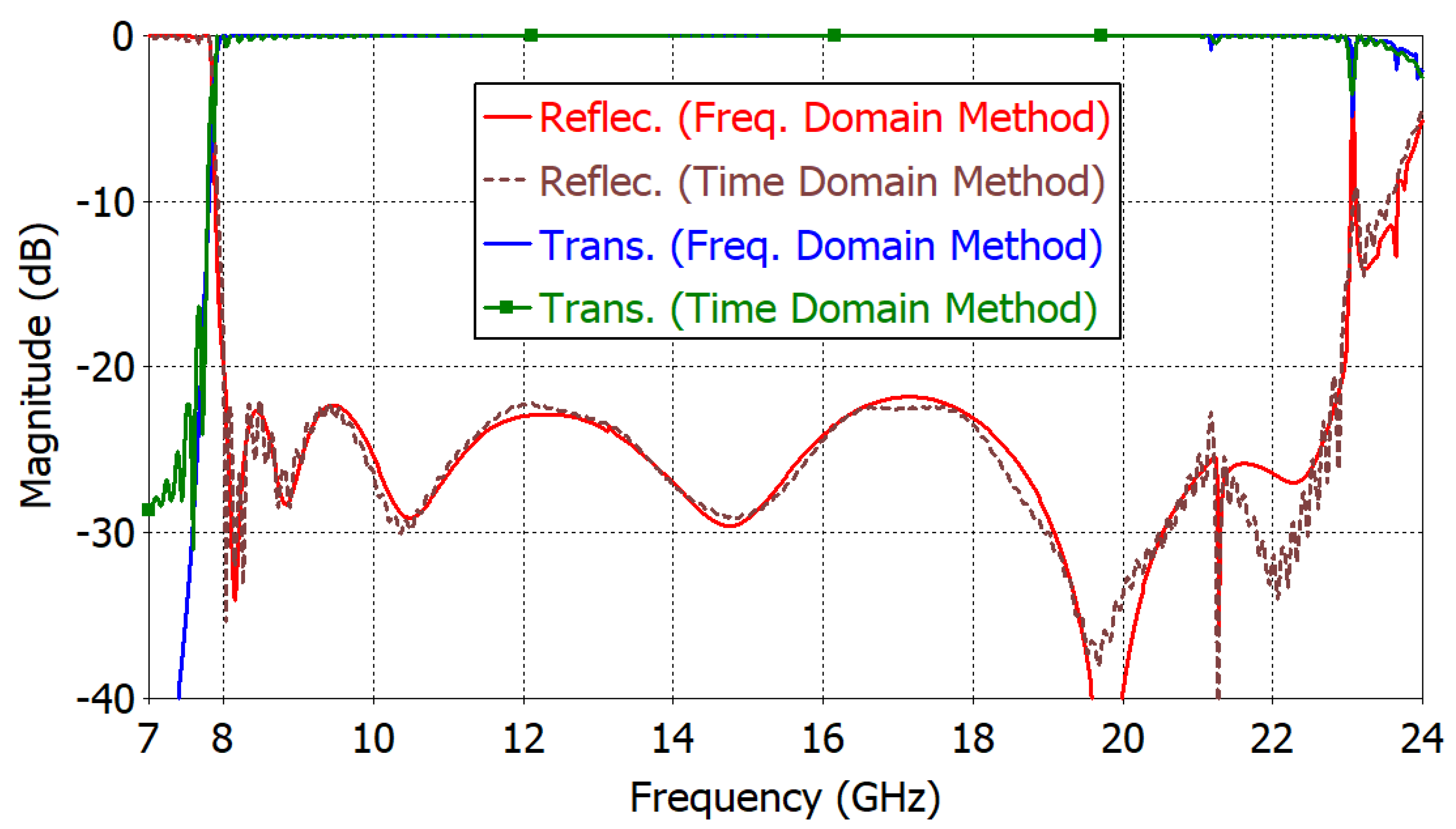
Figure 7 shows the reflection and transmission coefficients of the final design of the proposed adapter. They have been obtained using the time- and frequency-domain simulation methods in CST Studio SuiteTM V2023. The results from two different simulation schemes agree well with each other. The two transmission coefficients in blue and green overlap each other at 7.8–23.0 GHz. The transmission coefficient is determined by the reflection coefficient Γ via the relation 1 − |Γ|2. In a fabricated adapter, the transmission magnitude will be reduced by the finite conductivity of the conducting material and the contact resistance in the mating parts. The reflection coefficient is less than −20 dB at 8.00–22.95 GHz (2.87:1 bandwidth). In this frequency range, nulls can be observed (at 8.14, 8.86, 10.48, 14.76 and 19.67 GHz) in the reflection coefficient caused by the destructive interference of the reflections at the rectangular-to-circular waveguide transformer and at the coaxial-to-rectangular waveguide transformer.

4. Analysis of the Dominant and Higher-Order Modes

The performance of the proposed adapter is governed by the behavior of the dominant mode as well as that of the higher-order modes. This section presents an analysis of the dominant and higher-order modes in the designed adapter.
The bandwidth of the designed adapter is primarily determined by the transition between the coaxial cable R1 and the rectangular waveguide R3. When the bandwidth performance of the stepped-ridge transformer (S in Figure 2) is large enough, the lower limit of the operating frequency is governed by the broad wall dimensions of the waveguide guide R3, while the upper limit is determined by the excitation of higher-order modes. The lower operating frequency limits of the stepped-ridge transformer as well as that of the rectangular-to-circular waveguide taper (T in Figure 2) are very close to the fundamental mode’s cutoff frequency, as shown in Figure 6. The reflection coefficient of the rectangular-to-circular waveguide transition rises rapidly as the frequency approaches the cutoff frequency from above. The transition T shows a reflection coefficient of less than −20 dB from the lower frequency limit and upward.
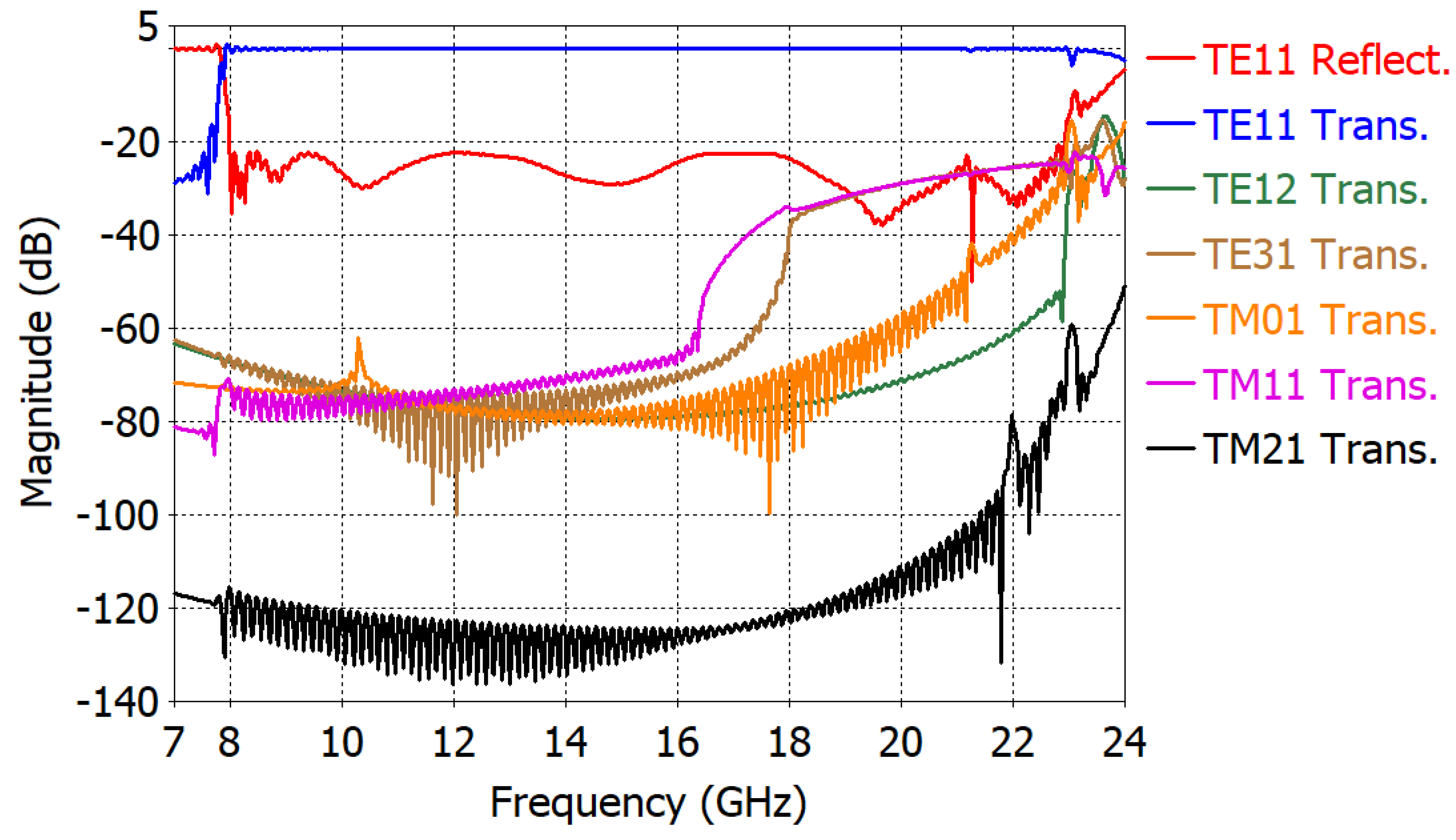
In any adapter, higher-order modes need to be sufficiently suppressed. Figure 8 shows the coefficient of transmission from the coaxial TEM mode to the fundamental TE11 and higher-order modes in the output circular waveguide along with the reflection coefficient of the TE11 mode. Compared to the level of the dominant TE11 mode, the higher-order mode level is less than −25.0 dB at the operating frequency range of 8.00–22.95 GHz. Above 22.95 GHz, the level of higher-order modes is greater than −25 dB. In Figure 8, the TM11 mode level is the largest, ranging from −40 dB to −25 dB at 17–23 GHz. The next largest mode is the TE31 mode, ranging from −40 dB to −25 dB at 18–23 GHz. The TM01 mode steadily increases from −60 dB at 20 GHz to −20 dB at 23 GHz, while the TE12 mode is less than −40 dB up to 23 GHz.
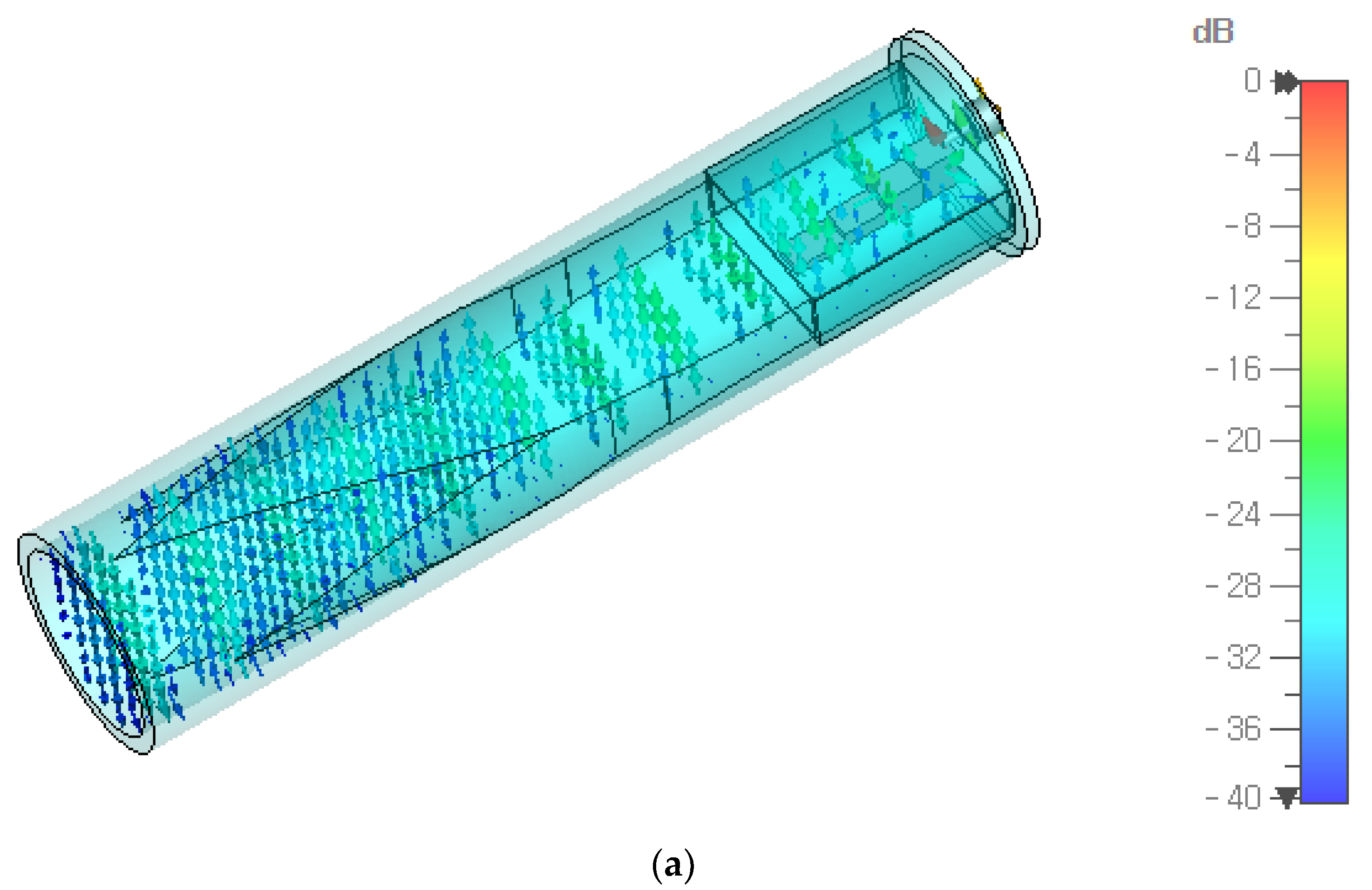
Figure 9 shows the electric and magnetic fields of the dominant mode inside the adapter at 15 GHz. The peak values of the electric and magnetic fields are uniform along the wave propagation direction, indicating a small voltage standing wave ratio (VSWR) and thus a good impedance matching performance.

5. Discussion

The adapter designed in this work operates from 8.00 GHz to 22.95 GHz with a reflection coefficient of less than −20 dB and higher-order mode level of less than −25 dB. This design has been made possible by the advanced capabilities of modern simulation tools and fast computing hardware (i.e., CPUs), as well as the adoption of advanced transition geometries in the design of the coaxial-to-rectangular waveguide and the rectangular-to-circular waveguide.
In Table 3, the adapter proposed in this paper is compared with previous works. The work in [11] is notable, despite being of the right-angle type, since it achieved a 2.42:1 bandwidth with a reflection coefficient of less than −20 dB. In [11], the levels of the higher-order modes have been included as well, while in many other works, including [16,19], they have not been given. The work in [19] achieves a 1.76:1 bandwidth with a −20-dB reflection. In [19], a three-step ridge transformer was employed as a coaxial-to-rectangular waveguide converter. A two-section octagonal waveguide converter was used between the rectangular and circular waveguides, which makes the structure very complicated.
As can be seen in Table 3, the bandwidth performance of the in-line, coaxial-to-circular waveguide adapter presented in this paper is 2.87:1, with a medium degree of structural complexity. In the authors’ opinion, this is a significant achievement considering that existing designs do not give a bandwidth greater than 2:1.

6. Conclusions

In this paper, a new in-line, coaxial-to-circular waveguide adapter operating over more than a one-octave bandwidth has been presented. A simulation-based design shows a bandwidth of 2.87 with a higher-order mode level of less than −25.0 dB. In existing designs of in-line, coaxial-to-circular waveguide adapters, the bandwidth is less than 2:1. The key idea in our design is the proper dimensioning of the waveguide and the optimization of the dimensions of the stepped-ridge converter, the matching cavity and the coaxial probe hole. With some additional work, it might be possible to further increase the upper limit of the operating frequency, which involves increasing the number of ridges in the coaxial-to-rectangular waveguide transformer and reducing the high-order mode level by employing continuous-slope curved transformer between the rectangular and circular waveguides.

Author Contributions

Conceptualization, E.A.; methodology, E.A., J.H. and S.X.; validation, C.-S.L., B.-C.A. and S.-G.C.; formal analysis, S.X., S.-S.K. and S.-G.C.; funding acquisition, S.-S.K. and S.-G.C.; writing—original draft, E.A.; writing—review and editing, B.-C.A., S.-S.K. and S.-G.C. All authors have read and agreed to the published version of the manuscript.

Funding

This work was supported by Innovative Human Resource Development for Local Intellectualization Program through the Institute of Information & Communications Technology Planning & Evaluation (IITP) grant funded by the Korean Government (IITP-2024-2020-0-01462).

Data Availability Statement

The data presented in this study are available in this article.

Conflicts of Interest

The authors declare that the research was conducted in the absence of any commercial or financial relationships that could be construed as potential conflicts of interest.

References

  1. Chakrabarty, S.B.; Singh, V.K.; Sharma, S.B. TM01 mode transducer using circular and rectangular waveguides. Int. J. RF Microw. Comp. Aided Eng. 2010, 20, 259–263. [Google Scholar] [CrossRef]
  2. Chittora, A.; Singh, S.; Sharma, A.; Mukherjee, J. Design of wideband coaxial-TEM to circular waveguide TM 01 mode transducer. In Proceedings of the 10th European Conference on Antennas and Propagation (EuCAP), Davos, Switzerland, 10–15 April 2016. [Google Scholar]
  3. Zhang, L.J.; Choi, S.G.; Ahn, B.C.; Bang, J.H.; Kim, D.H.; Choi, Y.T. Simplified feed prime focus reflector antenna. Microw. J. 2016, 59, 108–114. [Google Scholar]
  4. Jadhav, R.P.; Dongre, J.V.; Heddallikar, A. Design of X-band conical horn antenna using coaxial feed and improved design technique for bandwidth enhancement. In Proceedings of the 2017 International Conference on Computing, Communication, Control and Automation (ICCUBEA), Pune, India, 17–18 August 2017. [Google Scholar]
  5. Mallahzadeh, A.R.; Dastranj, A.A. Double-ridged conical horn antenna for 2–18 GHz. Electromagnetics 2008, 28, 450–461. [Google Scholar] [CrossRef]
  6. Solak, B.; Secmen, M.; Tekin, A. The design of a high gain dual-polarized quad-ridged circular horn antenna for wideband EMC test applications. Appl. Comput. Electromag. Soc. J. 2018, 33, 1009–1017. [Google Scholar]
  7. Göttmann, O.; Kaatze, U.; Petong, P. Coaxial to circular waveguide transition as high-precision easy-to-handle measuring cell for the broad band dielectric spectrometry of liquids. Meas. Sci. Technol. 1996, 7, 525. [Google Scholar] [CrossRef]
  8. Tantawi, S.G.; Nantista, C.D.; Bowden, G.B.; Fant, K.S.; Kroll, N.M.; Vlieks, A.E.; Chin, Y.H.; Hayano, H.; Vogel, V.F.; Nielson, J. Evaluation of the TE12 mode in circular waveguide for low-loss, high-power RF transmission. Rev. Mod. Phys. 2000, 3, 082001. [Google Scholar]
  9. De Ronde, F.C. Ideal w.g. to coax transitions using a fbm monopole. In Proceedings of the IEEE MTT-S International Microwave Symposium Digest, New York, NY, USA, 25–27 May 1988. [Google Scholar]
  10. Bialkowski, M.E. Analysis of a coaxial-to-waveguide adaptor including a discended probe and a tuning post. IEEE Trans. Microw. Theory Tech. 1995, 43, 344–349. [Google Scholar] [CrossRef]
  11. Bang, J.H.; Ahn, B.C. Coaxial-to-circular waveguide transition with broadband mode-free operation. Electron. Lett. 2014, 50, 1453–1454. [Google Scholar] [CrossRef]
  12. Simone, M.; Fanti, A.; Lodi, M.; Pisanu, T.; Mazzarella, G. An in-line coaxial-to-waveguide transition for Q-band single-feed-per-beam antenna systems. Appl. Sci. 2021, 11, 2524. [Google Scholar] [CrossRef]
  13. Cano, J.L.; Mediavilla, A. Octave bandwidth in-line rectangular waveguide-to-coaxial transition using oversized mode conversion. Electron. Lett. 2017, 53, 1370–1371. [Google Scholar] [CrossRef]
  14. Zhu, Q.C.; Williamson, A.G.; Neve, M.J. Design of coaxial line-to-circular waveguide transitions. In Proceedings of the IEEE MTT-S International Microwave Symposium Digest, Boston, MA, USA, 7–12 June 2009. [Google Scholar]
  15. Park, K.; Jeong, J. Design of Ku-band circular waveguide-to-coaxial adapter. In Proceedings of the 2018 Progress in Electromagnetics Research Symposium, Toyama, Japan, 1–4 August 2018. [Google Scholar]
  16. Schönfeld, F.; Weihreter, E.; Tasi, Y.C.; Chu, K.R. Layout of a broadband circular waveguide to coaxial transition. In Proceedings of the 5th European Particle Accelerator, Sitges, Spain, 10–14 June 1996. [Google Scholar]
  17. Yamamoto, T.; Urabe, K.; Tsuda, H. Analysis of coaxial-to-circular waveguide transition. In Proceedings of the IEEE Antennas and Propagation Society International Symposium (APSURSI), Memphis, TN, USA, 6–11 July 2014. [Google Scholar]
  18. Xia, L.; Li, J.L.; Ji, Z.; Gao, S.S. An in-line coaxial-to-circular waveguide transition at X band. J. Elecr. Eng. 2020, 71, 55–59. [Google Scholar] [CrossRef]
  19. Tribak, A.; Zbitou, J.; Sanchez, A.M.; Touhami, N.A. Ultra-broadband high efficiency mode converter. Prog. Electromag. Res. C 2013, 36, 145–158. [Google Scholar] [CrossRef]
  20. Yun, J.Y.; Nho, J.W.; Lee, C.H.; Park, Y.G.; Ahn, B.C. Design of a circular waveguide to coaxial cable transition employing a printed dipole (in Korean). J. Korean Inst. Inf. Tech. 2017, 15, 65–71. [Google Scholar]
  21. Marcuvitz, N. Waveguide Handbook; McGraw-Hill: New York, NY, USA, 1951; pp. 66–80. [Google Scholar]
  22. Das, B.N.; Sanyal, G.S. Coaxial-to-waveguide transition (end-launcher type). Proc. Inst. Electr. Eng. 1976, 123, 984–986. [Google Scholar] [CrossRef]
  23. Kim, D.-H.; Yang, D.-Y. Analysis and design of multiple-stepped coaxial coupling launcher for wideband rectangular waveguide excitation. J. Electr. Eng. Technol. 2021, 16, 2149–2155. [Google Scholar] [CrossRef]
  24. Niemann, F.L. Transitions from coaxial line to waveguide. In Microwave Transmission Circuits; Ragan, G.L., Ed.; McGraw-Hill: New York, NY, USA, 1948; pp. 314–361. [Google Scholar]
  25. Dix, J.C. Design of waveguide/coaxial transition for the band 2.5–4.1 Gc/s. Proc. Inst. Electr. Eng. 1963, 110, 253–255. [Google Scholar] [CrossRef]
  26. Gaudio, J.G.; Station, J.; Debski, T.R. Broadband Waveguide to Coaxial Line Transition. U.S. Patent 3,737,812, 5 June 1973. [Google Scholar]
  27. Chan, K.K.; Martin, R.; Chadwick, K. A broadband end launched coaxial-to-waveguide transition for waveguide phased arrays. In Proceedings of the IEEE Antennas and Propagation Society International Symposium, Atlanta, GA, USA, 21–26 June 1998. [Google Scholar]
  28. Levy, R.; Hendrick, L.-W. Analysis and synthesis of in-line coaxial-to-waveguide adapters. In Proceedings of the 2002 IEEE MTT-S International Microwave Symposium Digest, Seattle, WA, USA, 2–7 June 2002. [Google Scholar]
  29. Durga, M.; Tomar, S.; Singh, S.; Suthar, L. Millimeter wave in-line coaxial-to-rectangular waveguide transition. In Proceedings of the 2011 IEEE Applied Electromagnetics Conference (AEMC), Kolkata, India, 18–22 December 2011. [Google Scholar]
  30. Carmel, N.; Elmakayes, D.; Matzner, H. Investigation of a coax-to-waveguide transition element. In Proceedings of the 2011 IEEE International Conference on Microwaves, Communications, Antennas and Electronic Systems, Tel Aviv-Yafo, Israel, 7–9 November 2011. [Google Scholar]
  31. Gatti, R.V.; Rossi, R.; Dionigi, M. In-line stepped ridge coaxial-to-rectangular waveguide transition with capacitive coupling. Int. J. RF Microw. Comput. Aided Eng. 2018, 29, e21626. [Google Scholar] [CrossRef]
  32. Ye, J.; Zhang, H.; Chu, R. Analysis of a new method to design a coaxial-to-rectangular waveguide transition. In Proceedings of the 2019 International Applied Computational Electromagnetics Society Symposium-China (ACES), Nanjing, China, 8–11 August 2019. [Google Scholar]
  33. Bilik, V. High-power in-line waveguide to coaxial adapter. In Proceedings of the 2020 30th International Conference Radioelektronika (RADIOELEKTRONIKA), Bratislava, Slovakia, 15–16 April 2020. [Google Scholar]
  34. Shu, Y.; Ren, L. Novel waveguide connectors to simplify microwave and millimeter wave component packaging. In Proceedings of the 2022 IEEE/MTT-S International Microwave Symposium-IMS 2022, Denver, CO, USA, 19–24 June 2022. [Google Scholar]
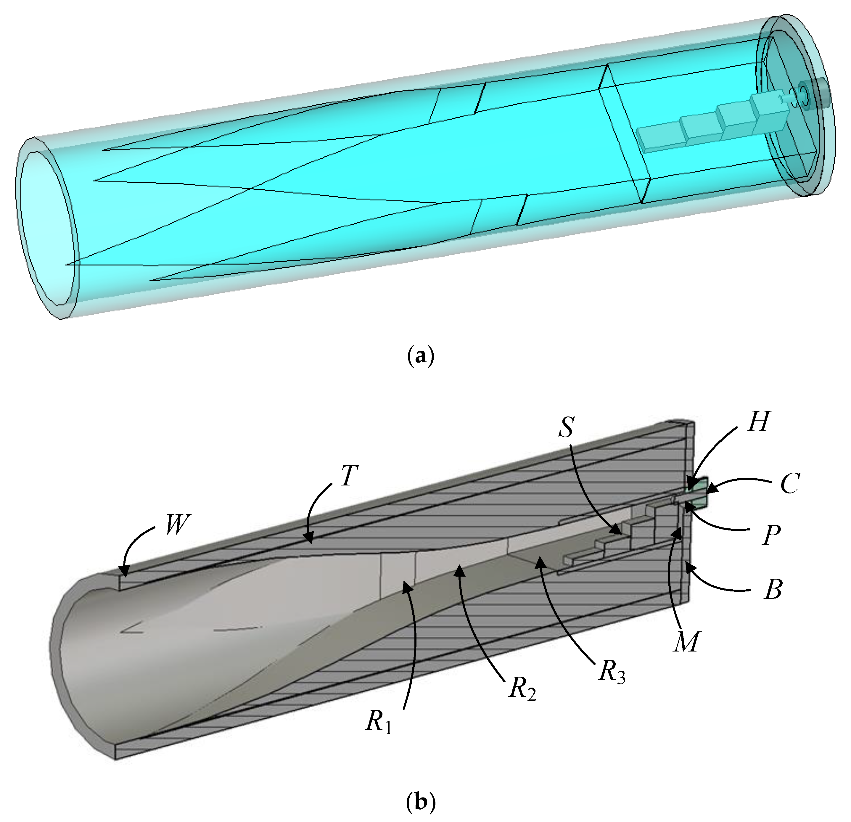
Figure 1. Structure of the proposed coaxial-to-circular waveguide adapter. (a) Transparent view and (b) cutaway view.
Symmetry 16 00304 g001
Figure 2. Dimensional parameters of the proposed adapter.
Symmetry 16 00304 g002
Figure 3. Electric fields at 50 GHz in the coaxial cable C in (a) TEM mode, (b) TE11 mode and (c) TE21 mode.
Symmetry 16 00304 g003
Figure 4. Electric fields at 50 GHz in the rectangular waveguide R3 in (a) TE10 mode, (b) TE11 mode and (c) TE30 mode.
Symmetry 16 00304 g004
Figure 5. Electric fields at 50 GHz in the circular waveguide W in (a) TE11 mode, (b) TM11 mode and (c) TE12 mode.
Symmetry 16 00304 g005
Figure 6. Reflection coefficients from the time-domain analysis of the coaxial-to-rectangular waveguide transformer and the rectangular-to-circular waveguide transformer in the proposed adapter.
Symmetry 16 00304 g006
Figure 7. Reflection and transmission coefficients from the time- and frequency-domain analyses of the proposed adapter.
Symmetry 16 00304 g007
Figure 8. Reflection coefficient of the TE11 mode and the transmission coefficient of higher-order modes in the output circular waveguide of the proposed adapter.
Symmetry 16 00304 g008
Figure 9. Electric (a) and magnetic (b) fields of the dominant mode inside the proposed adapter at 15 GHz.
Symmetry 16 00304 g009aSymmetry 16 00304 g009b
Table 1. Waveguide modes and cutoff frequencies in the proposed adapter.
WaveguideModes/Cutoff Frequency (GHz)
WTE11, TM11, TE12/7.88, 16.39, 22.80
R1TE10, TE11, TE30/7.87, 17.68, 23.61
R2TE10, TE11, TE30/7.70, 20.17, 23.10
R3TE10, TE11, TE30/7.54, 24.03, 22.61
CTEM, TE11, TE21/0.00, 26.27, 48.09
Table 2. Dimensions of the proposed adapter (unit: mm).
ParameterValueParameterValue
a1, b1, L119.05, 8.04–9.47, 6.73d, Lb, F, E22.31, 55.04, 1.91, 5.62
a2, b2, L219.47, 6.57–8.04, 18.22La, LS, t, G48.19, 21.96, 1.57, 1.06
a3, b3, L319.89, 6.57, 2.89Ridge width/height3.62/1.12, 2.14, 3.8, 5.33
Coax. cable1.27/4.11, εr = 2.08Probe holeDia. = 2.95, Len. = 1.57
Table 3. Comparison with previous works.
WorkTypeFrequency
(GHz)
Reflection
(dB)
Ratio
Bandwidth
Complexity
[11]Right-angle7.34–17.77−202.42Low (conical probe and tapered transformer)
[16]Right-angle0.7–3.0−104.29Medium (double ridge)
[19]In-line9.2–16.2−201.76High (coaxial-to-rectangular-to-circular)
[20]In-line13.6–17.9−151.32Medium (dielectrically filled; contains air gap)
This workIn-line8.00–22.95−202.87Medium (stepped ridge and spline taper converter)
Disclaimer/Publisher’s Note: The statements, opinions and data contained in all publications are solely those of the individual author(s) and contributor(s) and not of MDPI and/or the editor(s). MDPI and/or the editor(s) disclaim responsibility for any injury to people or property resulting from any ideas, methods, instructions or products referred to in the content.