Article

A Human-like Inverse Kinematics Algorithm of an Upper Limb Rehabilitation Exoskeleton

1
State Key Laboratory of Robotics and System, Harbin Institute of Technology, Harbin 150001, China
2
Department of Naval Architecture and Ocean Engineering, Harbin Institute of Technology (Weihai), Weihai 264209, China
*
Author to whom correspondence should be addressed.
Symmetry 2023, 15(9), 1657; https://doi.org/10.3390/sym15091657
Submission received: 8 August 2023 / Revised: 22 August 2023 / Accepted: 22 August 2023 / Published: 28 August 2023

Abstract

:
Powered exoskeleton rehabilitation is an effective way to help stroke patients recover their motor abilities. Bionic structures and human-like control strategies can be used to enhance both the safety and efficacy of exoskeletons. However, the motion characteristics of the shoulder complex are not sufficiently considered. In this paper, we designed a 7-degrees-of-freedom (DOF) upper limb rehabilitation exoskeleton, FREE (functional rehabilitation exoskeleton). The mechanical structures of the shoulder and forearm of FREE are in accordance with human anatomy, and can be used to perform a wide range of synergistic motion of multiple joints while keeping a safe distance from the patient’s head. A multiple-input-multiple-output (MIMO) shoulder girdle motion prediction model was developed to satisfy the synergy between humans and exoskeletons. Moreover, a constrained task priority and projected gradient-based inverse kinematics algorithm (CTPPG-IK) was proposed to achieve assistance with scapulohumeral rhythm. A motion capture system was used to collect different activities of daily life (ADL) motion data to validate the proposed algorithm. The experimental results show that the accuracy of the prediction model is higher than that of existing models, and the inverse kinematics algorithm can handle the end-effector task and joint space with a maximum angle error of 3.04 × 10 3 rad.

1. Introduction

Stroke has been a widespread and serious global healthcare problem, with the highest rate of disability for a single disease. There were 13.7-million new cases of stroke worldwide in 2016, and this number has continued to rise [1]. The most common and widely recognized impairment following stroke is motor impairment, and rehabilitation is an effective way to help patients regain their motor abilities [2]. To date, several rehabilitation robots have been used to improve both motor control and strength in post-stroke upper extremity paralysis, which can help speed up neural remodeling significantly, and appear to be safe [3,4,5,6].
The upper limb is one of the many redundant subsystems of the human body and is commonly considered to have 7 DOF, consisting of three at the shoulder, one at the elbow, and three at the wrist. Positioning the wrist in space and orienting the palm is a task that requires only 6 DOF [7]. Mechanical engineers have drawn inspiration from human upper limb to design spherical–roll–spherical (SRS) robots such as KUKA IIWA and Franka Panda. However, the acromioclavicular joint in the shoulder actually provides additional degrees of freedom, a feature that is often overlooked in the design of exoskeletons. To ensure a safe and comfortable human–robot interface, precise alignment between the exoskeletal and anatomical joint axes throughout movement phases is critical. This prevents the generation of harmful tangential forces on soft tissues and joints, minimizing the risk of discomfort or injury. There are some exoskeletons that use passive self-alignment to achieve center alignment of the shoulders. ASSISTON-SE is equipped with a 3RRP parallel back-drivable mechanism, allowing for passive translational movements of the center of the GH joint and enabling independent active control of these DOFs [8]. NESM- γ has an adjustable trunk link with passive ball joints at the two ends and connects the back of the user and the robot, allowing for unconstrained movements of the scapula [9]. Based on the concept of posture synergies, a semi-actuated upper limb exoskeleton Armule was designed, which achieves 5 DOF motion of the upper limb with two motors [10,11]. The above-mentioned exoskeletons are adjustable according to the user characteristics, provide repetitive active and passive assistance, accelerate neural remodeling, and record user motion data, but there are also limitations. For example, exoskeletons do not fully match to the upper limb kinetic chain, resulting in insufficient active degrees of freedom, safety, sensing and learning capabilities, and comfort.Therefore, the design objectives of the exoskeleton mainly include the following four points: (1) redundant active degrees of freedom, (2) bionic structure, (3) non-collision with the user, and (4) torque sensing and control [12,13].
Nevertheless, the passive alignment method may have problems, such as lack of adaptability, low comfort, and a complicated process for putting it on and taking it off, so only a few exoskeletons have active shoulder compensation mechanisms currently [14,15]. This limitation affects the patient’s ability to perform functional movements in rehabilitation training, potentially causing discomfort and compensatory movements. Furthermore, realizing the intuitive and ergonomic interaction between the user and exoskeleton can significantly enhance the rehabilitation outcomes. One key requirement is that the exoskeleton generates natural and anthropomorphic movements [16]. Human upper limb movements not only focus on the hand’s motion but also the coordination between joints. In the realm of robot kinematics, they correspond to task space and joint space movements, respectively [17].
Rehabilitation exoskeletons are highly coupled to human limbs; thus, the corresponding kinematics approach deserves more consideration. There are several approaches to the inverse kinematics (IK) of exoskeletons, including analytic geometry methods, learning-based methods, and differential kinematics. Analytic methods based on the task space are efficient and fast [18,19,20,21]. These methods require the parameterization of the upper limb in advance. Learning-based methods are usually computed in the joint space, enable exoskeletons to learn and reproduce the patient’s movements in an unstructured environment, and imitate human movement habits [22,23,24]. This method is applicable to nonstrict motion trajectories and require significant computational resources during the training phase. Differential kinematics can be combined with the gradient projection method to complete end-effector tasks and optimize the joint motions of redundant robots [25,26,27]. A kinematically redundant robot is a mechanism that has more DOF than are required to perform a given task. The upper limbs are redundant with respect to the 6 DOF of the hand, so upper limb exoskeletons should also be kinematically redundant for flexible manipulation. For these robots, the problem generally cannot be solved analytically and has an infinite number of solutions, so numerical methods are usually used to solve local optimization problems under joint angle constraints [28,29]. Most of the existing research studies assisted patients with tasks of the hand but did not take into account the movement patterns of the upper limb. Scapulohumeral rhythm is a kinematic interaction between the scapula and humerus, and results in non-coincidence between the center of the exoskeletal shoulder and the humeral origin. In the absence of kinematic restrictions, exoskeletons may compress or pull patients and cause pain. Therefore, the IK which unifies end-effector tasks and synergistic movement among links is worth researching. However, few studies have integrated scapulohumeral rhythm and kinematic approaches. The relative inclination angle and geodesics in Riemannian space were used to plan human-like paths [30].
Overall, the main contribution of this paper is as follows:
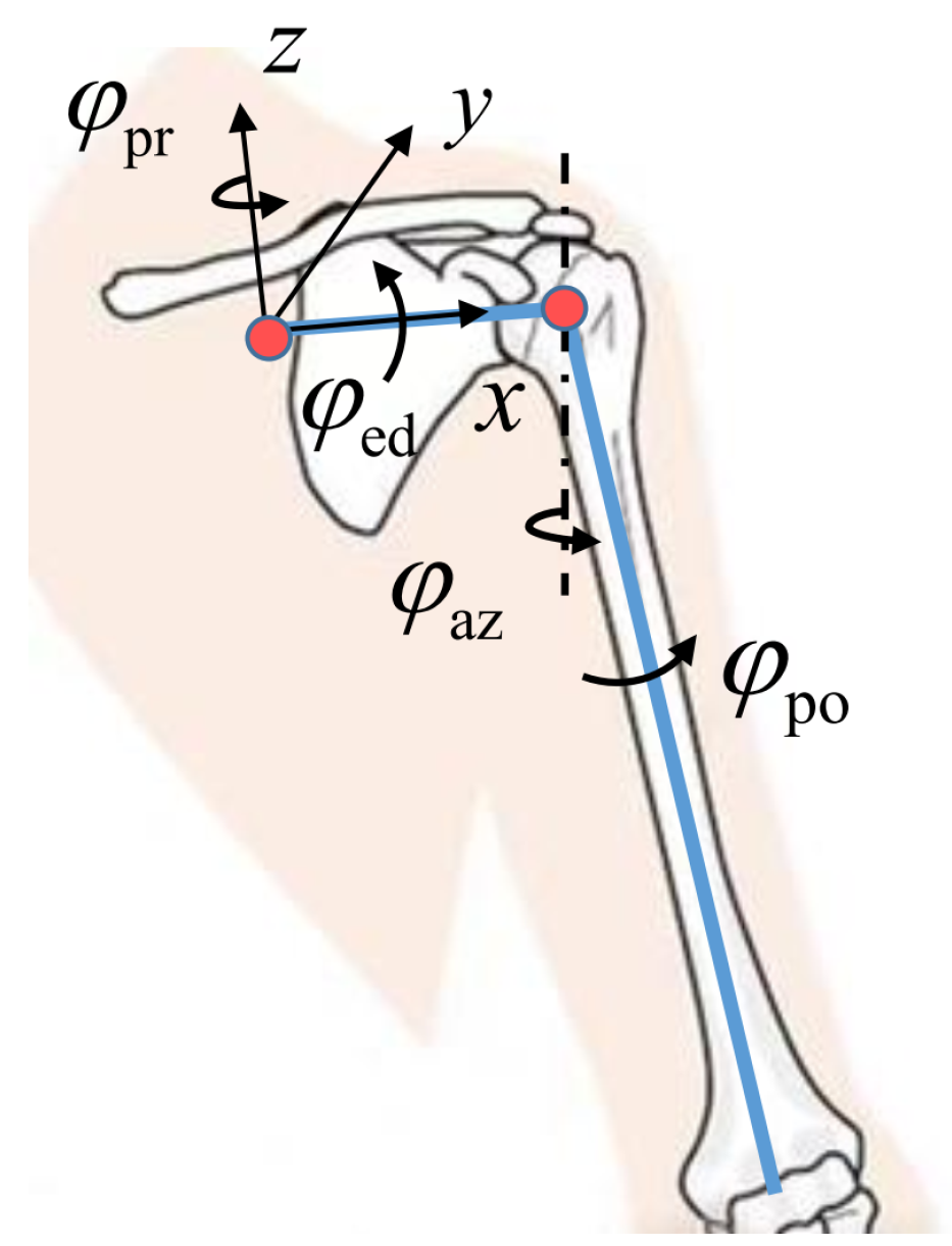
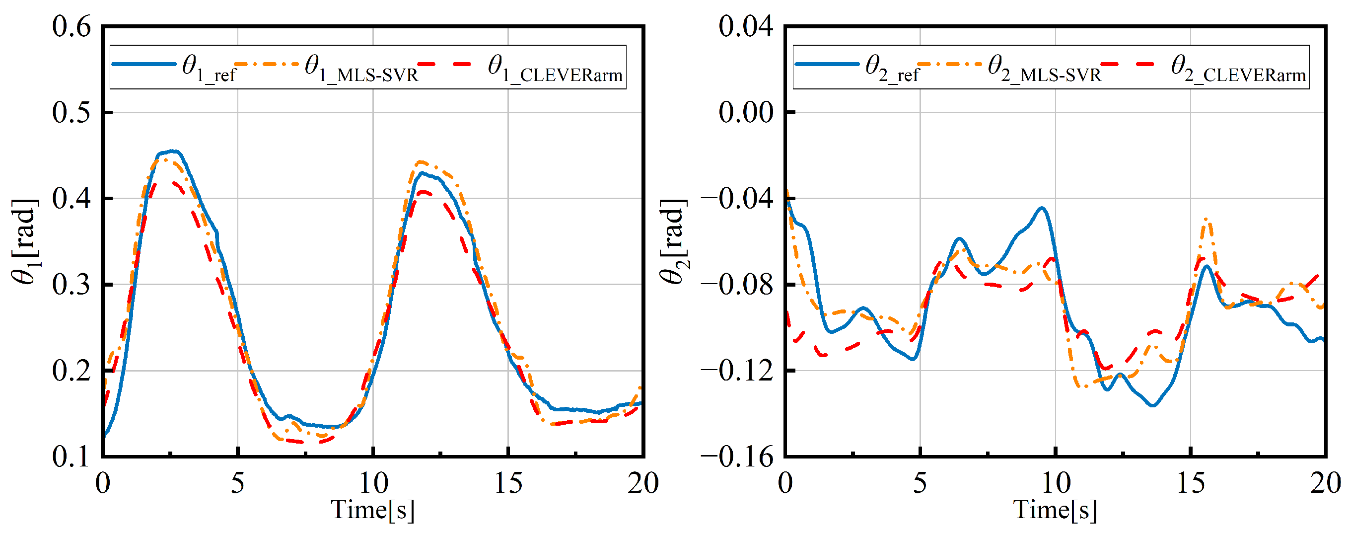
  • A multiple-input multiple-output (MIMO) shoulder girdle motion prediction model is proposed. It can be used to estimate elevation/depression and protraction/retraction angles of the shoulder girdle based on the humerus orientation.
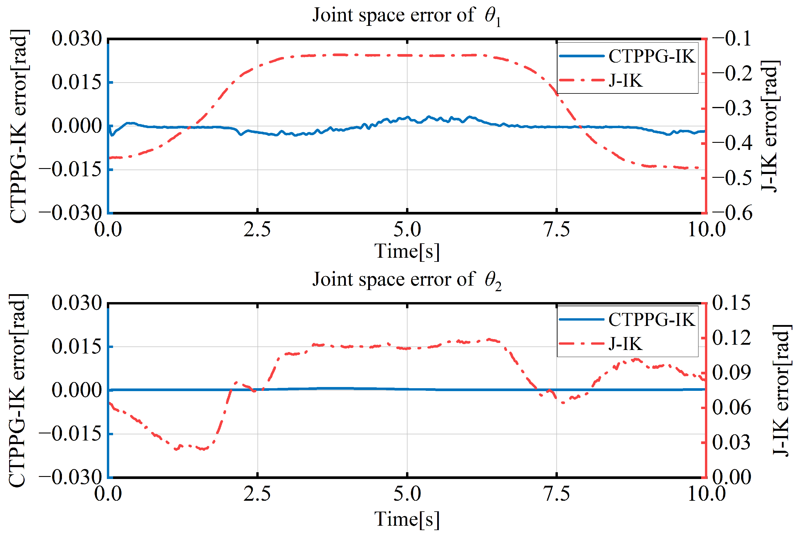
  • An IK algorithm that integrates the gradient projection method and task priority is proposed and validated. It enables FREE to achieve human-like shoulder movement.
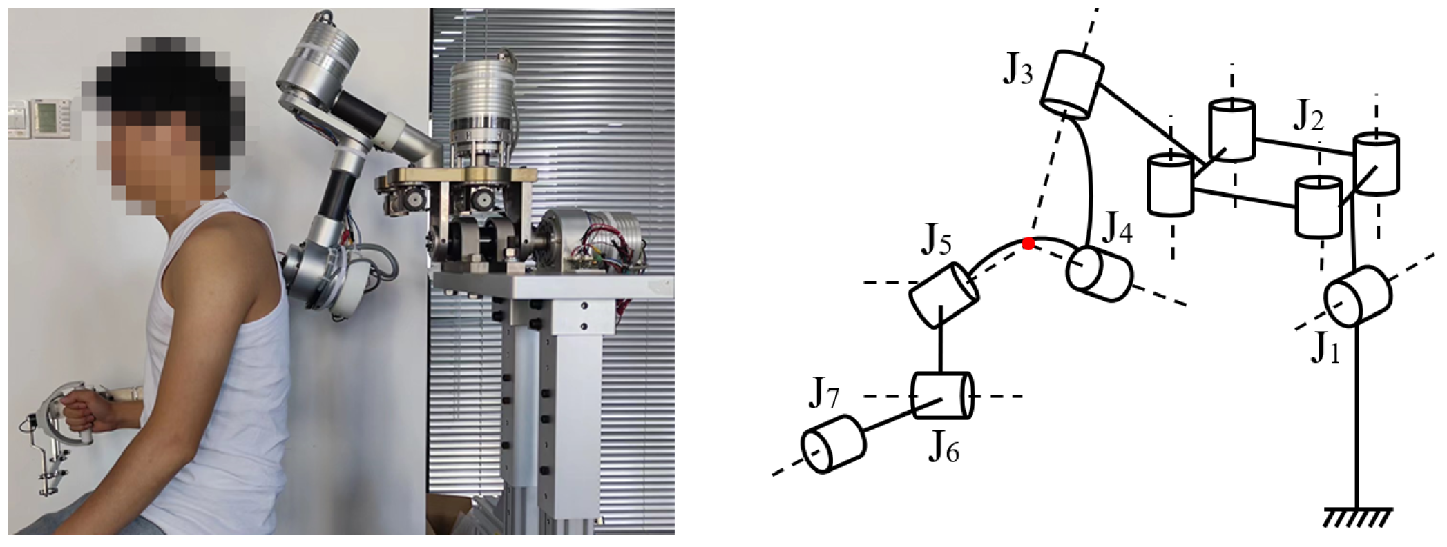
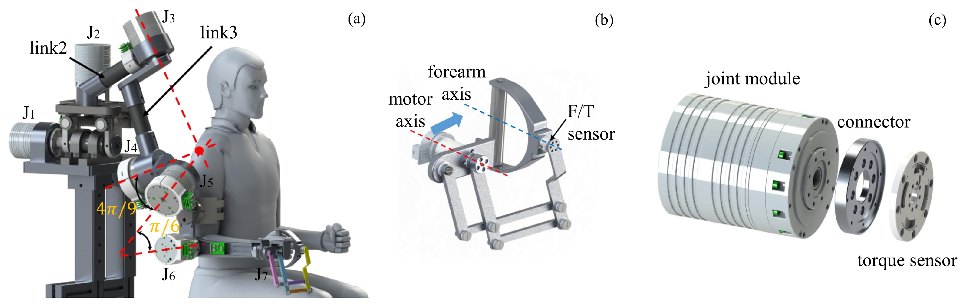
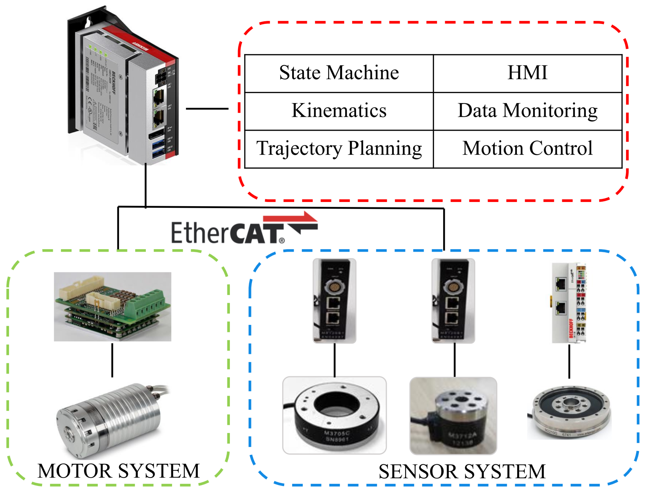
2. System Design

The FREE exoskeleton was developed to assist patients with functional rehabilitation training after stroke. Seven motors shown in Figure 1 were configured to achieve shoulder joint, elbow joint and forearm motion after compromises. The exoskeleton is capable of shoulder girdle elevation/depression and forward extension/retraction; shoulder joint abduction/adduction and flexion/extension; glenohumeral (GH) joint self-rotation; elbow flexion/extension; and forearm pronation/supination. To increase the applicability of the exoskeleton, the upper arm and forearm were designed as a split structure for length adjustment. To improve the stiffness of the exoskeleton and reduce its mass, the body was mainly made of aluminum material and carbon fiber tubes.
J1–J5 were used to construct the exoskeleton shoulder joint. The GH joint is a visual characterization of shoulder motion. Almost all voluntary movements of the shoulder joint involve movement at the GH joint; this requires additional degrees of freedom to ensure that the GH joint is in central alignment with the exoskeleton shoulder during rehabilitation training [31]. To achieve synchronization between the exoskeleton and shoulder without overlap, a parallelogram was used for translation of the axis of rotation of the scapulohumeral out of the patient’s body.
The 3D model of FREE is shown in Figure 2a. In order to achieve a wide range of ROM, FREE adopts a serial chain with three revolute joints that encircle the upper arm for the ball-and-socket joint to match GH. The angle between the two adjacent axes is set at 4 π / 9 rad to ensure sufficient manipulability of shoulder. In order to achieve a greater level of horizontal extension, the upper arm linkage exists a π / 6 rad bend. This configuration places the singularities at the edge of the ROM while leaving a safety distance of more than 40 mm between the human and exoskeleton. A new linkage structure was developed to achieve pronation/supination of the forearm shown in Figure 2b. This structure consists of only five connecting links, which can translate the forearm rotation axis into the isometric plane beyond exoskeleton links. Compared to ARMin [32], this structure weighs only 210 g with the same range of motion (approximately 8 π / 9 rad), dramatically reducing weight while having lower structural complexity.
The controller was designed based on the industrial PC CX6015-0100 (Beckhoff Automation Inc., Verl, Germany) under the software environment of TwinCAT3, and the hardware architecture is shown in Figure 3. Both the control algorithm and the communication cycle were strictly kept to 1 ms.

3. Kinematics Algorithm

Human upper limbs are able to perform various movements dexterously thanks to its kinematic redundancy. In order to match the kinematics of the patient’s upper extremity, the designed exoskeleton contains seven joints with redundant degrees of freedom. After planning the path of a set of rehabilitation motions, the joint angles are calculated by IK. Although the analytical geometry method is fast and always finds a usable solution, it is applicable only to robots of a specific configuration and is incompatible with the constraints of the joint space. For FREE, the ball-and-socket joint was placed at the midpoint of the kinematic chain; it is difficult to decouple the position from orientation. In addition, it is difficult to obtain the analytical solution of a redundant exoskeleton in the absence of an arm angle constraint, in advance. In this section, a model is constructed to predict the motion of the shoulder girdle for the constraint of scapulohumeral rhythm. A task priority and projected gradient-based IK solution method is proposed and prioritized for multiple tasks to improve the human–robot coordination during rehabilitation training.

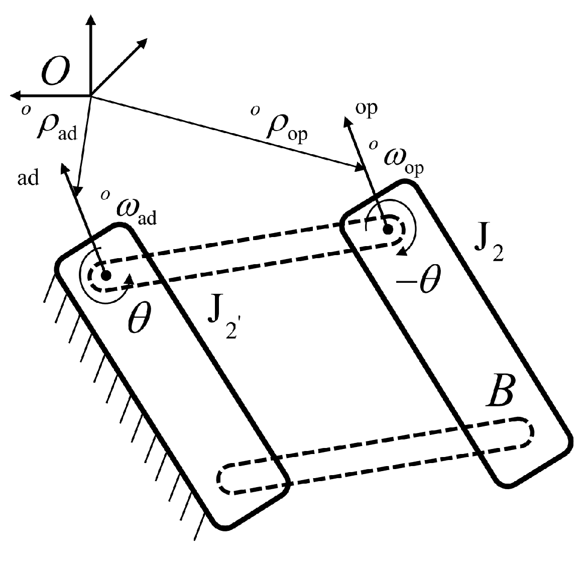
3.1. Human Shoulder Kinematics

In order to coordinate movements between exoskeletons and patients, it is of the utmost importance to clarify the kinematic properties of the human upper limb, especially the shoulder complex. The shoulder complex consists of four sub-joints. Though each joint has independent degrees of freedom, the shoulder complex can be considered a compound mechanism, where all four joints must properly interact for normal shoulder motion to occur. A case in point for this interaction is the scapulohumeral rhythm, which is the relationship between the elevation of the scapulohumeral joint and the upward rotation of the scapula. Reference [30] used two polynomials to describe the relationship between the polar angle of the humerus and the elevation/depression and protraction/retraction of the scapulohumeral joint; however, this description is not comprehensive. In addition, movements of the shoulder girdle are associated with φ az in Figure 4. As the humerus of the upper arm moves, the scapulohumeral follows fixed patterns. Reference [33] shows that using several independent regression models may not be able to accurately describe the movement of the scapula and humerus bones. They maintain a non-linear relationship in multiple dimensions of motion.
The coupled movements of the shoulder joint result in a nonlinear relationship between the movement angles of the humerus and scapulohumeral. One common approach to dealing with multi-input multi-output regression problems is to build multiple multi-input single-output models and predict each variable separately. We trained and merged two BP neural networks but the prediction performance for φ pr was suboptimal. In order to improve prediction accuracy, the relationship can be abstracted into a MIMO model that takes into account the potential correlations between different outputs; however, it has not currently been applied in the human joint angles prediction domain. Xu presented a MLS-SVR multi-output algorithm, in a multi-output setting with a strong generalization capability [34]. Considering the limited amount of data and the requirement for a smooth fit, MLS-SVR was chosen as a predictor of the rotation angles of the shoulder girdle. A motion capture system can be used to record the movements of the upper limbs and calculate the four predefined sets of angles. Let y = [ φ ed , φ pr ] R n × m , x = [ φ ed , φ pr ] R n × p , where n is the sample size, and m and p represents the number of dimensions for the output and input variables, respectively. The multi-output regression is regarded as finding the mapping between an input matrix [ φ po , φ az ] and an output matrix [ φ ed , φ pr ] .
In order to achieve accurate prediction of shoulder joint angles, the optimal parameters of prediction model need to be solved. The goal of the MLS-SVR algorithm is to find a function f ( x ) = φ ( x ) T W + b that has the maximum deviation from the actual observed output and is as flat as possible, where W R h × l , b R l , l is the dimension of the output variable, and  φ ( x ) is a a mapping function to achieve the linear regression of data in high-dimensional space. The element w i R h of W can be written as w i = w 0 + v i . w 0 represents the mean vector, while small values of the vector v i R h indicate that the different outputs are similar to one another. The flatness of the function f ( x ) can be obtained by minimizing the value of the parameters w 0 T w 0 and t r a c e ( V T V ) , which is equivalent to finding a small value for W, where V = ( v 1 , v 2 , , v l ) R h × l . Therefore, the optimization problem could be attained by minimizing the following objective function while satisfying the constraint:
min J w 0 , V , Ξ = 1 2 w 0 T w 0 + γ 2 l t r a c e V T V + γ 2 t r a c e Ξ T Ξ
s . t . y = Z T W + r e p m a t b T , l , 1 + Ξ
where Ξ = ξ 1 , ξ 2 , , ξ l R n × l consists of slack variables, b = b 1 , b 2 , , b l R l , γ and γ are hyper-parameters, Z = φ x 1 , φ x 2 , , φ x n R h × n . The optimization in Equations (1) and (2) can be made into a Lagrange function as follows:
L w 0 , V , b , Ξ , A = J w 0 , V , Ξ t r a c e ( A T ( Z T W + r e p m a t b T , n , 1 + Ξ y ) )
where A = α 1 , α 2 , , α m R l × m is a matrix consisting of Lagrange multipliers. After eliminating W and Ξ according to the KKT condition, the following linear equation system can be determined:
0 l × l N T N M b α = 0 l y
where N = b l o c k d i a g ( 1 n , 1 n , , 1 n ) R l n × l , Ω = r e p m a t ( K ˜ , l , l ) R l n × l n , M = Ω + γ 1 I l n + l / γ Q R l n × l n is a positive definite matrix, K ˜ = Z T Z R n × n is a matrix that contains the kernel function, and Q = b l o c k d i a g ( K ˜ , K ˜ , , K ˜ ) R l n × l n , α = α 1 T , α 2 T , , α m T T R m l . However, solving the linear equation system (4) directly is difficult because it is not positively definite. Therefore, the equation was reformulated into the following equation:
G 0 l × l n 0 l n × l M b M 1 N b + α = N T M 1 y y
where G = N M 1 N R l × l is a positive definite matrix. Then, the solution b ˜ and α ˜ can be calculated by b ˜ = G 1 N T H 1 y and α ˜ = M 1 ( y N b ) , and the MLS-SVR decision function can be obtained as follows:
f ˜ ( x ) = φ ( x ) T W ˜ + b ˜ T = φ ( x ) T r e p m a t ( w 0 ˜ , 1 , l ) + φ ( x ) T V ˜ + b ˜ T = φ ( x ) T r e p m a t k = 1 l Z T α ˜ k , 1 , l + l γ φ ( x ) T Z A ˜ + b ˜ T = r e p m a t j = 1 l i = 1 n α ˜ i j K x , x i , 1 , l + l γ i = 1 n α ˜ i K x , x i + b ˜ T
In this study, the RBF (radial basis function) kernel was used because it has only one hyper-parameter and is computationally efficient: K x , x i = e x p σ x x i 2 , σ > 0 . This approach can be used to predict φ pr and φ ed . They can be set as the target angles of θ 1 and θ 2 , and  θ 1 and θ 2 are actual joint values of exoskeletons. In addition, in order to reduce jitter in the prediction results and to prevent drastic changes in the angular velocities of the joints, a zero-phase low-pass filter was added after the prediction model. The cutoff frequency was set to 15 Hz.

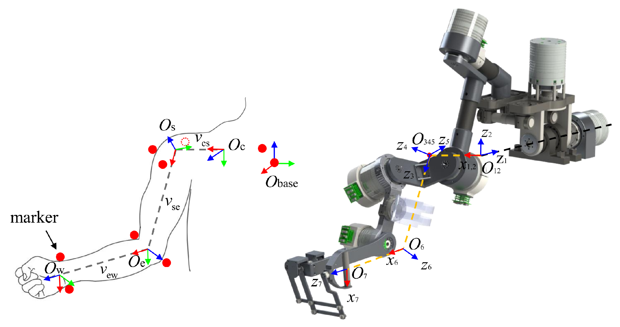
3.2. Robot Kinematics

The standard Denavit–Hartenberg (SDH) convention is a widely used approach for robot modeling. However, it suffers from a significant drawback when dealing with robots that have tree-like or closed-chain structures, where some links may possess more than one axis of rotation. In such cases, employing the SDH method to establish link coordinate systems can lead to ambiguities. FREE features a closed-chain structure in its shoulder girdle. Consequently, the local coordinate system of each link of FREE was established according to the modified Denavit–Hartenberg (MDH) convention. Figure 5 shows the parallelogram structure of exoskeleton shoulder. Because of the presence of the parallelogram linkage at the shoulder girdle, the exoskeleton is modeled differently from the joint kinematics of the open-chain robot. Assuming a local coordinate system attached to the fixed end of the parallelogram, the linkage relative to the fixed end only changes its position but not its orientation during the motion of the mechanism.
The body twist can be defined as the spatial velocity in the body frame, expressed as
V b = ω b v b = o ω o ω × o ρ θ ˙
where V b is the spatial velocity of body B with respect to a fixed frame. ω b and v b are the angular and linear velocity vectors of the instant point on the rigid body, respectively. o ω and o ρ are the direction and location vectors of the rotational axis with respect to the fixed frame, respectively. θ ˙ is the angular velocity of the link with respect to the rotational axis. When the parallelogram rotates, the link adjacent to the fixed end rotates at an angular velocity θ ˙ , and the link opposite to the fixed end rotates at an angular velocity θ ˙ . Therefore, the kinematic rotation of the parallelogram mechanism can be rewritten as
V b = o ω a d o ρ a d × o ω a d θ ˙ + o ω o p o ρ o p × o ω o p ( θ ˙ ) = 0 ( o ρ o p o ρ a d ) × o ω θ ˙ = o s ^ p θ ˙
where o ω a d , o ρ a d , o ω o p , and  o ρ o p are the direction and location vectors of the joint axis of each link adjacent to and opposite to the fixed end. o s ^ p is the spatial vector on the output side of the parallelogram. o ω is the component of spatial velocity. Determining the end effector motion from a given joint motion is the subject of the forward kinematics problem. The MDH parameters of FREE are shown in Table 1.
By using IK, the angle of each robot joint can be solved, given the position and direction of the endpoint. However, for redundant robots, the Jacobi matrix is not a square, and thus the inverse matrix cannot be directly solved. One solution is to use pseudo-inverse substitution. At the velocity level, they are expressed in a vector called the Jacobian IK (J-IK) form as
x ˙ = J θ ˙
θ ˙ = J x ˙
where x ˙ is the m-dimensional linear and rotational velocities vector of the end effector, and θ ˙ is the n-dimensional joint angles vector. J is the m × n robot Jacobian matrix, and the n × n matrix J is the pseudo-inverse of J, also called the Moore–Penrose inverse of J. It can be computed as J = J T J J T 1 . The pseudo-inverse gives the best possible solution to Equation (7) in the sense of least squares; however, the pseudo-inverse has stability problems in the region adjacent to the singularity. If the configuration is close to the singularity, then the pseudo-inverse method will lead to drastic changes in the joint angles, exceeding even the limit of joint velocity, even if the desired speed is extremely small.
The damped least squares method (DLS) avoids many of the singularity problems of the pseudo-inverse method and gives a numerically stable solution, which was first used for IK by Nakamura [35]. Thus, J was rewritten as J D :
J D = J T J J T + λ 2 I 1
The pseudo-inverse solution of Equation (8) minimizes the two-norm number of the joint velocity vector; however, the posture of the exoskeleton in this case may not match the current posture of the patient’s upper limb. For rehabilitation exoskeletons, it is clearly important to maintain kinematic consistency with the patient’s upper extremities. The redundant exoskeleton design can achieve this requirement. The projected gradient method was first proposed to solve IK with the pseudo-inverse [36]. The discrete form is used in place of the differential form for computational convenience as
Δ θ = J D Δ x + k ( I J D J ) ξ 1
where ξ 1 is an arbitrary vector, and I is a n × n identity matrix. ( I J J ) is an operator which projects ξ 1 onto the null space of the Jacobian J such that ξ 1 can be interpreted as a desired velocity behavior that is only effective in the null space and does not interfere with task achievement. While FREE has 7 degrees of freedom, it has insufficient redundancy to perform the end-effector task after constraining both joint angles of the shoulder girdle mechanism. This is equivalent to controlling the remaining five joints to complete 6 DOF end-effector tasks. Under constraints of certain subtasks, if all the variables orientation and position are used to calculate the joint angles, it may cause a mismatch between the task and redundant degrees of freedom, and thus the solution will fail. Orientation-related tasks and position-related tasks are decoupled at the human wrist. In ADL motions, position-related tasks affect the distance error of the motions, while orientation-related tasks are related to human habits and comfort. For example, a user always grasps a bottle in the habitual posture, but this can be performed by grasping either the top or the bottom of the bottle to complete the task. Exoskeletons should perform shoulder assist and forearm posture tasks while maximizing the position of the end effector. Orientation errors between the end effector of the exoskeleton and patient’s wrist may lead to discomfort and injury. Therefore, exoskeletons should perform suitable orientation-related tasks while maximizing shoulder assistance and minimizing the position error of the end effector. For this scenario, we use priority-based task control with task orientation as the main priority and the task position as the secondary priority, while introducing constraints on the human shoulder. Therefore, the end-effector task can be divided into orientation-related and position-related tasks [37], with orientation-related tasks having a higher priority in this study:
Δ θ = J ω Δ x ω + k ( I J ω J ω ) H shr ( θ ) + ξ v
H shr ( θ ) = 1 2 i = 1 2 θ i θ ^ i 2
where the first term on the right side corresponds to the high-priority orientation task, and the second term corresponds to the sub-priority task containing the end position and shoulder constraints. J ω and J v are the first and last three rows of J D , which are associated with the angular and linear velocities, respectively. x ω and x v are the first and last three rows of x, which are associated with the orientation and position, respectively. ξ v = J v Δ x v represents the spatial vector of the linear velocities subtask. H shr ( θ ) represents the joint space loss function, which is used to regulate the synchronized motion of the exoskeleton with the user’s shoulder; shr is short for shoulder. H shr ( θ ) = k ( θ θ ^ ) represents the gradient of H shr ( θ ) ; when H shr ( θ ) 0 , this term adjusts the angle of the shoulder movement in the direction of the gradient. θ ^ i represents the desired shoulder girdle movement angle, i.e., the previously mentioned φ ed and φ pr . The weight factor is fixed to k = 1 in this study. The pseudocode is given below, where ori is short for orientation and t o l is a small positive tolerance of task error. The complete pseudocode is given in Algorithm 1:
Algorithm 1 Constrained task-priority and projected-gradient IK algorithm (CTPPG-IK).
1:
while  e ori > t o l ori & & e joint > t o l joint 1 & & e joint > t o l joint 2 do
2:
     compute Δ x i , J D ( θ i ) , φ ed , φ pr , Δ x ω , Δ x v , J ω , J v
3:
     θ ^ = [ φ ed , φ pr ] T
4:
     ξ v = J v Δ x v
5:
     H shr ( θ ) = [ k ( θ i θ ^ ) , 0 , 0 , 0 , 0 , 0 ] T
6:
     Δ θ i = J ω Δ x ω + k ( I J ω J ω ) H shr ( θ ) + ξ v
7:
     θ i + 1 = θ i + Δ θ i
8:
     compute x i + 1
9:
     e ori = | | x ω ( i + 1 ) x ω ( i ) | |
10:
     [ e joint 1 , e joint 2 ] T = [ I 2 × 2 , 0 2 × 5 ] θ i + 1 θ ^
11:
     i = i + 1
12:
end while

3.3. Convert Generated Motion to Exoskeleton Motion

In an ideal scenario, it is expected for the motion of the user’s upper limb and the exoskeleton to be perfectly synchronized. However, due to the presence of redundant DOF, using the markers set on the user’s wrist to obtain the Cartesian trajectory of the end effector and solving for the joint angles vector θ of the exoskeleton cannot guarantee motion synchrony. The goal of this study is to accurately predict the shoulder joint angle and enable human-like auxiliary movements for the exoskeleton; motions in the upper limb configuration space can be mapped to the exoskeleton configuration space by the analytical geometry method. The shoulder complex, upper arm and forearm, which make up the human upper limb, can be simplified as three vectors in series. The simplified systems are shown in Figure 6.
The origins of the local coordinate of link 1 and link 2 are coincident and denoted as O 12 . Similarly, the origin of the local coordinate of link 3, link 4, and link 5 are coincident and denoted as O 345 . When z 1 is aligned with the center of the ball on the shoulder girdle, the user’s upper arm and forearm lengths are parallel and congruent to those of the FREE. The vector set of FREE is equivalent to those of the upper limb in kinematics, and O c , O s , O e , and O w coincide with O 12 , O 345 , O 6 , and O 7 , respectively. The coordinates of O c can be calculated by the least squares method using the data of the GH center. The orientation and position transform can be obtained by a homogeneous rotation matrix of MDH as follows:
T i i 1 = 0 n R 0 n P 0 1 = c θ i s θ i 0 a i c α i s θ i c α i c θ i s α i d i s α i s α i s θ i s α i c θ i c α i d i c α i 0 0 0 1
The coordinates of points O c , O s , O e , and O w in the world coordinate system can be directly obtained by the motion capture system. The vector v cs , v se , and v ew can be calculated by taking the difference between adjacent reference points. According to the principle of motion synchrony, it is easy to observe that the shoulder girdle angles of FREE θ 1 b and θ 2 b correspond to those of the user φ ed and φ pr , respectively. θ i b represents the baseline angle of each joint of the exoskeleton. θ 1 b and θ 2 b can be calculated by bringing them into forward kinematics calculations as shown in the following formula:
v cs = T 2 0 ( 1 : 3 , 4 )
Similarly, θ 3 b , θ 4 b and θ 5 b can be calculated by v se as follows:
v se = T 5 2 ( 1 : 3 , 4 )
θ 6 b is the angle between v se and v ew , and θ 7 b is the angle between v se and v ew as follows:
θ 6 b = π / 2 x s , x e x s x e , θ 7 b = z e , z w z e z w
This calculation method has a clear geometric meaning and ensures both the consistency of the end trajectories and the synchronization of the kinematic chains. The calculated θ i b is the baseline joint angles vector, which can be used to calculate the error of the shoulder angles prediction model. By calculating the forward kinematics through θ i b , the obtained trajectory can be considered the baseline trajectory. This trajectory can be used to calculate the end-effect error.

4. Experiments and Results

To validate the proposed human-like kinematics algorithm, our experimental objectives are twofold: (1) assess the precision of the shoulder girdle motion prediction model, and (2) examine the ability of FREE to achieve rehabilitation actions while simultaneously satisfying both shoulder and end-effector constraints by utilizing the joint angles calculated by the prediction model.

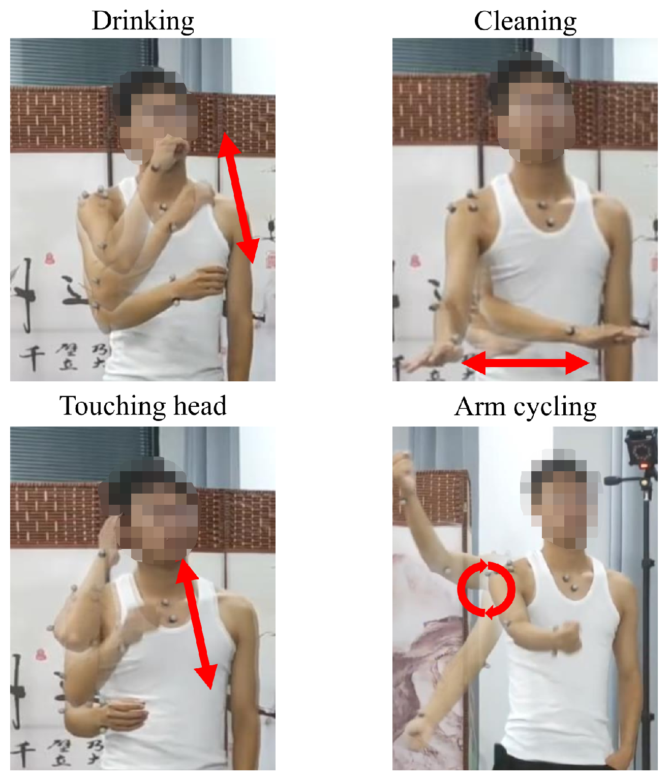
4.1. Experimental Protocol

Users of different body sizes have different shoulder rhythms, which lead to variability in the prediction model parameters. In order to make the prediction model as accurate as possible in predicting the shoulder girdle angle for a specific user, one right-handed healthy subject (male, age: 24 years, height: 177 cm, weight: 60.5 kg) volunteered to participate in the study. The testing was performed with the informed consent of the volunteer and in a protocol approved by the Declaration of Helsinki. This experiment is a benign behavioral intervention for adults. The experiment was completed in a quiet indoor environment and was completely free of charge. Volunteers were fully informed of the procedure and content of the experiment, and they signed an informed agreement. To ensure the rigor of the experiment and the accuracy of the results, the definition of a joint coordinate system for the shoulder, elbow, and wrist, proposed by the Standardization and Terminology Committee (STC) of the International Society of Biomechanics (ISB), was used [38]. An optical motion capture system with eight cameras (Mars2H, Nokov, sampling rate 60 Hz) was used to record the data of motions and reflectable marker points as the reference sensing method. The volunteers performed four ADL motions in Figure 7: reaching to the mouth (drinking/eating), cleaning the table, touching the head, and arm cycling.
The first three motions have a small ROM and a fixed pattern, and the last motion includes a larger ROM amplitude. Data containing information from a wide ROM helped identify relatively accurate humeral–clavicular kinematic patterns at the baseline. In order to avoid occlusion of the markers and ensure no data loss, movements in the experiment were performed at a slower pace compared to those in daily life. The volunteer was asked to complete each movement ten times in sequence within a two-minute time frame to ensure the continuity of data. During the whole process, the volunteers tried to keep the torso as immobile as possible. The experiment was conducted twice, with one dataset used for training the prediction model and the other dataset used to generate reference movements.

4.2. Data Processing and Analysis Criteria

To compute the values of α and b to predict cleaning, drinking, and arm circulation, the data of these three motions were used to train the predictive models as shown in Equation (3). After training was completed, to evaluate the performance of the shoulder girdle angles prediction model, R-square and RMSE indices were used. In order to validate the performance of the algorithms, the analytic geometry method was used to solve the predefined movement angles of the subject’s upper limbs at first. Next, forward kinematics calculations were performed, and the desired task trajectory was obtained based on the kinematic agreement between the subject and the exoskeleton. Lastly, J-IK and CTPPG-IK were used to calculate the joint space angle and compare the performance of both. The computation of kinematics and data processing in the simulation environment were completed offline. Then, we saved each set of joint angles in .csv format in the industrial PC and used the position control mode on the exoskeleton for experimental validation. The maximum joint space error of θ 1 and θ 2 are E θ 1 and E θ 2 . The maximum orientation error of the end effector is E ω .

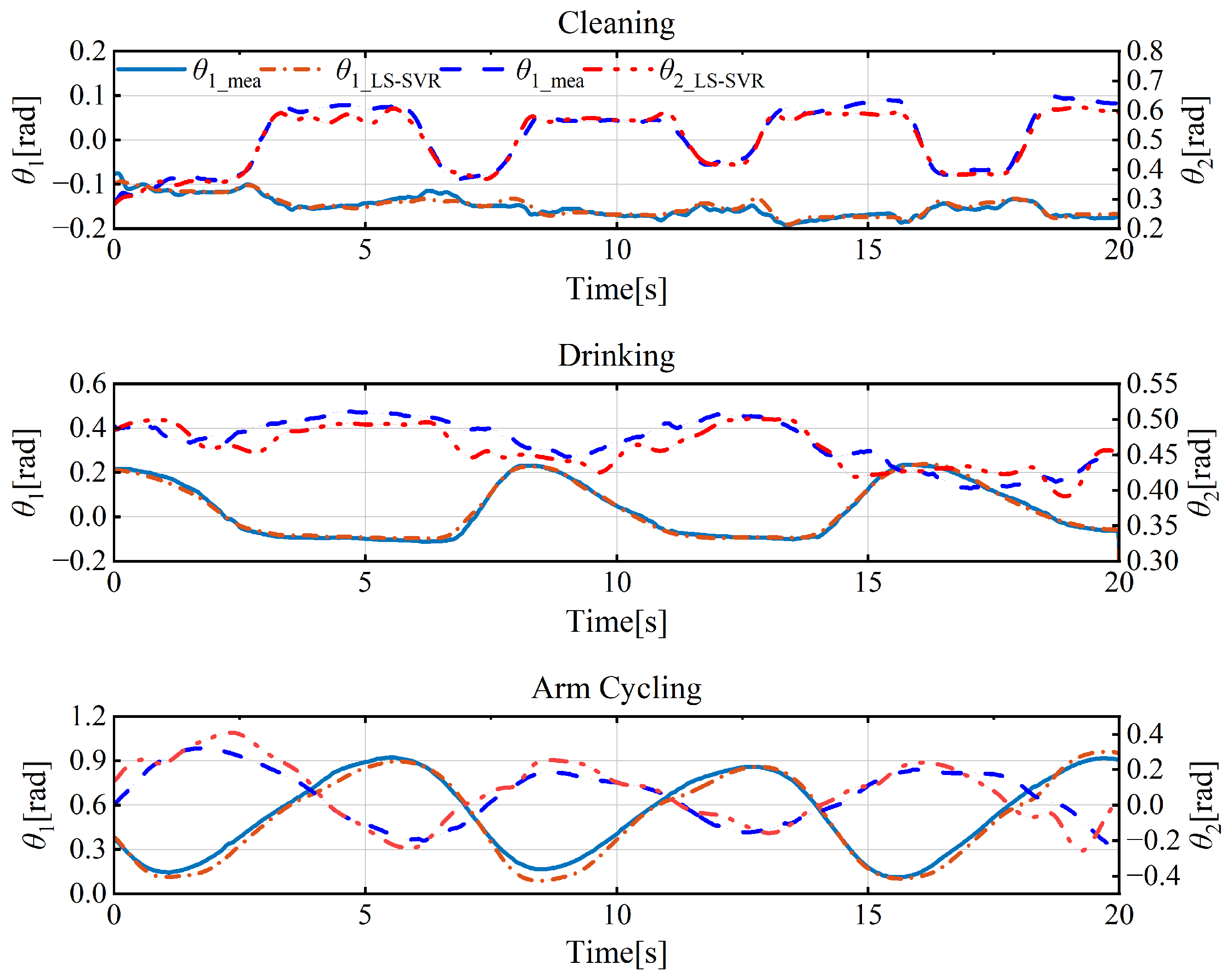
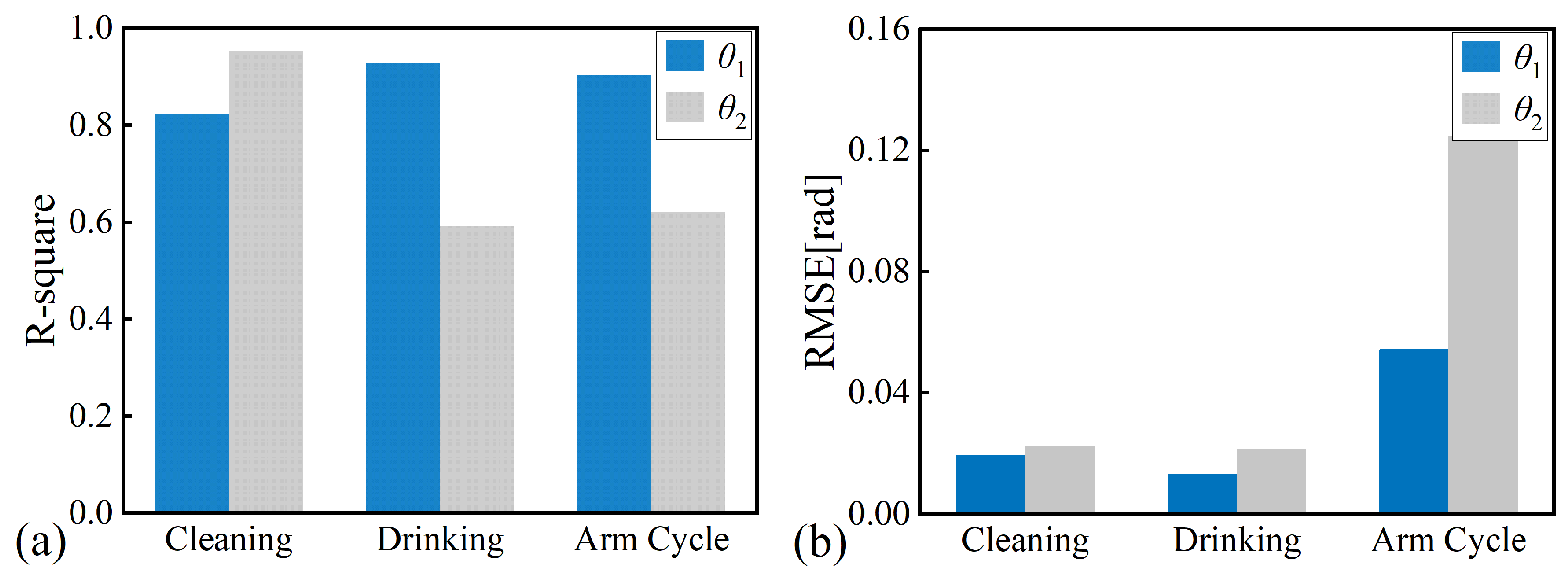
4.3. Results and Discussion

Figure 8 shows the rotation angles of the volunteer’s shoulder girdle during different motions relative to the angles predicted by MLS-SVR. The sky blue and dark blue lines represent the measurement data of the motion capture system, the orange and red lines represent the output angles of the prediction model, respectively. Figure 9 shows the estimation accuracy of θ 1 and θ 2 . R-square values of θ 1 exceeded 0.8 in all three movements, indicating that the prediction model was more accurate for elevation/depression than the shoulder girdle protraction/retraction.
The R-square of θ 2 is 0.952 in cleaning, and 0.592 and 0.621 in drinking and arm cycling, respectively. Figure 9b also shows fluctuations in the prediction of θ 2 . Through the analysis of the raw data, it could be found that θ 1 has uniform periodic variation in the drinking and arm cycling, while θ 2 has a significant decrease in cycling consistency. Shoulder joint elevation is small, and the motion is dominated by anterior protraction and retraction during cleaning motion, thus causing the R-square deviation of θ 2 in each group. The ROM of arm cycling is larger than the first two sets of motions, which is a reason for its higher RMSE.
CLEVERarm developed two polynomial models relating the movements of the GH center and arm elevations, employed through elevation/depression and protraction/retraction experiments [30]. However, there is a strong correlation between the elevation/depression angle and the type of movement. In addition, that study differed from this paper in that the center of motion of the shoulder girdle was set on the axis of symmetry of the coronal plane. The polynomial models were retained, and the parameters were re-fitted using the data for the touching head action, and used as a reference as follows:
φ e d = 4.33 × 10 3 ε 3 6.86 × 10 2 ε 2 + 0.062 ε + 0.05
φ p r = 1.89 × 10 5 ε 4 + 4.53 × 10 5 ε 3 3.72 × 10 2 ε 2 + 0.014 ε 0.194
where ε = φ p o . Figure 10 shows the comparison of the MLS-SVR model and the polynomials model during the touching head movement. The figure on the left shows the prediction performance of the two models of θ 1 . The RMSEs of θ 1 errors of the MLS-SVR and polynomial model were 0.0201 rad and 0.0242 rad, and the maximum errors were 0.0275 rad and 0.0543 rad, respectively. Both models were able to predict θ 1 relatively accurately, with the MLS-SVR model having slightly higher precision. In the right figure, the reference angle θ 2 was between −0.15 rad and −0.03 rad. The RMSEs of θ 2 errors of the MLS-SVR and polynomial model were 0.0125 rad and 0.0237 rad, and the maximum errors were 0.0218 rad and 0.0565 rad, respectively. The two indicators of the polynomial model are approximately twice those of the MLS-SVR model, and the maximum error is approximately 57.6% of the range of motion. Therefore, the MLS-SVR model has a significantly superior predictive performance. When considering both dimensions of motion, the MLS-SVR model shows better prediction precision.
Figure 11 shows the joint space angle errors using the J-IK algorithm and the CTPPG-IK algorithm for a segment of the volunteer head-touching trajectory, where θ e r r o r = θ i d θ i . These errors represent the differences between these two algorithms and the baseline joint angles θ i d mentioned in Section 3, respectively. We set the joint space convergence threshold to 3.5 × 10 3 rad, so the exoskeleton is guaranteed to have a small error in tracking the shoulder girdle rotation angles predicted by the humerus. In contrast, the joint angles error calculated by J-IK is several orders of magnitude higher than that of CTPPG-IK, and the absolute values of the maximum errors for θ 1 and θ 2 are 0.4707rad and 0.1190rad, respectively. CTPPG-IK is a closed-loop method for adjusting the shoulder girdle orientation for the next cycle based on the predicted humeral spherical coordinate angles for θ 1 and θ 2 in the previous sampling cycle. In contrast, the joint rotation angles calculated by J-IK are the least two parametric solutions of the solution space, and each joint needs an angle as small as possible to achieve the end-effector task.
The performance metrics comparative experiments are shown in Table 2. The maximum of the joint space error of J-IK is much larger than that of CTPPG-IK. The maximum values of E θ 1 and E θ 2 by CTPPG-IK are 2.07 × 10 3 and 3.04 × 10 3 rad during arm cycling, respectively, which proves that CTPPG-IK has good performance in tracking the shoulder rhythm of the subject. The maximum values of E θ 1 and E θ 2 by J-IK are 2.98 × 10 1 rad and 1.79 × 10 1 rad, representing the motion mismatch of the shoulder joints of the subject with the exoskeleton’s shoulder girdle. The joint space error of J-IK increases as the shoulder girdle moves away from the initial position due to the cumulative error caused by the least squares solution.

5. Discussion

Nowadays, researchers in the literature have significantly explored intelligent techniques to solve the non-closed form equations for IK problems of more than 4-DOFs manipulators, such as genetic algorithms [39], Bayesian optimization [40], particle swarm optimization [41], and artificial neural networks [42]. In general, evolutionary algorithms are good choices for applications where a real-time solution is needed. Artificial neural networks are a good choice for applications where a more accurate solution is needed. However, these methods could be computationally expensive and may not always converge to the global optimum solution. Additionally, neural networks need a significant amount of training data and computing resources. Compared to these methods, the algorithm proposed in this paper takes into account the constraints of scapulohumeral rhythm. By projecting the predicted shoulder angles into null space, this algorithm typically requires only 2–5 iterations to determine joint angles that satisfy the constraints. The algorithm has a well-defined mathematical formulation and can meet the requirements for real-time computation.
While we employed the DLS method to mitigate excessive joint velocities near singular points and did not observe significant issues in the current experiments, constraints on velocity aspects should still be incorporated to enhance safety during practical use. Furthermore, 7 DOF is not redundant enough for the dexterous manipulation of the upper limb. We contemplate the addition of more joints to better align the exoskeleton with upper limb movements.

6. Conclusions

We designed a 7-degrees-of-freedom upper limb rehabilitation exoskeleton, FREE, which can be used to conduct a variety of rehabilitation training and improve the synergy of movement. A MIMO prediction model was used to predict shoulder girdle motion by scapulohumeral orientation. Only the elevation angle of the upper arm is the input in the existing model. In this study, both the impact of upper arm movement on the shoulder girdle elevation/depression and the protraction/retraction were simultaneously considered to establish a MIMO model to predict shoulder girdle angles. A human-like CTPPG-IK algorithm based on differential kinematics was proposed to handle multiple constraints in exoskeleton assistance. The CTPPG-IK algorithm combines the gradient-projection method with task priority-based control, which ensures both the degree of completion of the rehabilitation motions and the natural shoulder motion. The maximum errors of θ 1 and θ 2 are 2.07 × 10 3 and 3.04 × 10 3 rad, respectively. And most importantly, based on CTPPG-IK, FREE can be used to customize shoulder motion to match the characteristics of wearers.
In the future, an online parameter identification method will be developed to obtain both the shoulder girdle rotation center coordinate and scapulohumeral rhythm. In addition, the configuration parameters of FREE will be optimized according to the Asian body shape to match more wearers. Currently, experiments are not being conducted with users wearing FREE. We will conduct actual rehabilitation experiments after refining the compliant control.

Author Contributions

Conceptualization, S.P. and J.W.; methodology, S.P., J.W. and Y.Y.; validation, S.P. and J.W.; formal analysis, S.P.; investigation, J.G., H.Y. and Y.Y.; resources, J.G. and Y.Y.; data curation, J.G., H.Y. and Y.Y.; writing—original draft preparation, S.P.; writing—review and editing, S.P.; visualization, S.P. and J.W.; supervision, J.G., H.Y. and Y.Y.; project administration, Y.Y.; funding acquisition, Y.Y. All authors have read and agreed to the published version of the manuscript.

Funding

This study was funded by the Major Research Plan of National Natural Science Foundation of China (Grant NO. 91648106).

Institutional Review Board Statement

All experimental protocols and methods were approved by the Medical Ethics Committee of Harbin Institute of Technology with Ethics No: HIT-2023043 and carried out in accordance with relevant guidelines and regulations. This study confirms that informed consent was obtained from all subjects and/or their legal guardians.

Data Availability Statement

The datasets generated and analyzed during the current study are available from the corresponding author on reasonable request.

Conflicts of Interest

The authors declare that they have no known competing financial interests or personal relationships that could have appeared to influence the work reported in this paper.

References

  1. Adamson, J.; Beswick, A.; Ebrahim, S. Is stroke the most common cause of disability? J. Stroke Cerebrovasc. Dis. 2004, 13, 171–177. [Google Scholar] [CrossRef]
  2. Kwakkel, G.; Veerbeek, J.M.; van Wegen, E.E.; Wolf, S.L. Constraint-induced movement therapy after stroke. Lancet Neurol. 2015, 14, 224–234. [Google Scholar] [CrossRef] [PubMed]
  3. Duret, C.; Grosmaire, A.G.; Krebs, H.I. Robot-assisted therapy in upper extremity hemiparesis: Overview of an evidence-based approach. Front. Neurol. 2019, 10, 412. [Google Scholar] [CrossRef] [PubMed]
  4. Sun, J.; Shen, Y.; Rosen, J. Sensor reduction, estimation, and control of an upper-limb exoskeleton. IEEE Robot. Autom. Lett. 2021, 6, 1012–1019. [Google Scholar] [CrossRef]
  5. Wang, J.; Barry, O.R. Inverse optimal robust adaptive controller for upper limb rehabilitation exoskeletons with inertia and load uncertainties. IEEE Robot. Autom. Lett. 2021, 6, 2171–2178. [Google Scholar] [CrossRef]
  6. Xu, K.; Li, W.; Ji, C.; Liu, B. Study on Control Technology of Tendon Bionic Driving Robot System. J. Bionic Eng. 2023, 20, 584–597. [Google Scholar] [CrossRef]
  7. Perry, J.C.; Powell, J.M.; Rosen, J. Isotropy of an Upper Limb Exoskeleton and the Kinematics and Dynamics of the Human Arm. Appl. Bionics Biomech. 2009, 6, 175–191. [Google Scholar] [CrossRef]
  8. Ergin, M.A.; Patoglu, V. ASSISTON-SE: A self-aligning shoulder-elbow exoskeleton. In Proceedings of the 2012 IEEE International Conference on Robotics and Automation, St Paul, MN, USA, 14–18 May 2012; pp. 2479–2485. [Google Scholar]
  9. Pan, J.; Astarita, D.; Baldoni, A.; Dell’Agnello, F.; Crea, S.; Vitiello, N.; Trigili, E. NESM-γ: An upper-limb exoskeleton with compliant actuators for clinical deployment. IEEE Robot. Autom. Lett. 2022, 7, 7708–7715. [Google Scholar] [CrossRef]
  10. He, L.; Xiong, C.; Liu, K.; Huang, J.; He, C.; Chen, W. Mechatronic design of a synergetic upper limb exoskeletal robot and wrench-based assistive control. J. Bionic Eng. 2018, 15, 247–259. [Google Scholar] [CrossRef]
  11. He, C.; Xiong, C.H.; Chen, Z.J.; Fan, W.; Huang, X.L.; Fu, C. Preliminary assessment of a postural synergy-based exoskeleton for post-stroke upper limb rehabilitation. IEEE Trans. Neural Syst. Rehabil. Eng. 2021, 29, 1795–1805. [Google Scholar] [CrossRef]
  12. Xu, P.; Xia, D.; Li, J.; Zhou, J.; Xie, L. Execution and perception of upper limb exoskeleton for stroke patients: A systematic review. Intell. Serv. Robot. 2022, 15, 557–578. [Google Scholar] [CrossRef]
  13. Narayan, J.; Kalita, B.; Dwivedy, S.K. Development of robot-based upper limb devices for rehabilitation purposes: A systematic review. Augment. Hum. Res. 2021, 6, 1–33. [Google Scholar] [CrossRef]
  14. Zeiaee, A.; Zarrin, R.S.; Eib, A.; Langari, R.; Tafreshi, R. CLEVERarm: A Lightweight and Compact Exoskeleton for Upper-Limb Rehabilitation. IEEE Robot. Autom. Lett. 2021, 7, 1880–1887. [Google Scholar] [CrossRef]
  15. Kim, B.; Deshpande, A.D. An upper-body rehabilitation exoskeleton Harmony with an anatomical shoulder mechanism: Design, modeling, control, and performance evaluation. Int. J. Robot. Res. 2017, 36, 414–435. [Google Scholar] [CrossRef]
  16. Yang, X.; Huang, T.H.; Hu, H.; Yu, S.; Zhang, S.; Zhou, X.; Carriero, A.; Yue, G.; Su, H. Spine-inspired continuum soft exoskeleton for stoop lifting assistance. IEEE Robot. Autom. Lett. 2019, 4, 4547–4554. [Google Scholar] [CrossRef]
  17. Burdet, E.; Franklin, D.W.; Milner, T.E. Human Robotics: Neuromechanics and Motor Control; MIT Press: Cambridge, MA, USA, 2013. [Google Scholar]
  18. Brahmi, B.; Saad, M.; Rahman, M.H.; Ochoa-Luna, C. Cartesian trajectory tracking of a 7-DOF exoskeleton robot based on human inverse kinematics. IEEE Trans. Syst. Man. Cybern. Syst. 2017, 49, 600–611. [Google Scholar] [CrossRef]
  19. Kim, H.; Miller, L.M.; Byl, N.; Abrams, G.M.; Rosen, J. Redundancy resolution of the human arm and an upper limb exoskeleton. IEEE Trans. Biomed. Eng. 2012, 59, 1770–1779. [Google Scholar]
  20. Jung, Y.; Bae, J. Kinematic analysis of a 5-dof upper-limb exoskeleton with a tilted and vertically translating shoulder joint. IEEE/ASME Trans. Mechatronics 2014, 20, 1428–1439. [Google Scholar] [CrossRef]
  21. Wu, K.Y.; Su, Y.Y.; Yu, Y.L.; Lin, C.H.; Lan, C.C. A 5-degrees-of-freedom lightweight elbow-wrist exoskeleton for forearm fine-motion rehabilitation. IEEE/ASME Trans. Mechatronics 2019, 24, 2684–2695. [Google Scholar] [CrossRef]
  22. Lauretti, C.; Cordella, F.; Ciancio, A.; Trigili, E.; Catalan, J.; Badesa, F.; Crea, S.; Pagliara, S.; Sterzi, S.; Vitiello, N.; et al. Learning by demonstration for motion planning of upper-limb exoskeletons. Front. Neurorobot. 2018, 12, 5. [Google Scholar] [CrossRef]
  23. Deng, M.; Li, Z.; Kang, Y.; Chen, C.P.; Chu, X. A learning-based hierarchical control scheme for an exoskeleton robot in human–robot cooperative manipulation. IEEE Trans. Cybern. 2018, 50, 112–125. [Google Scholar] [CrossRef]
  24. Averta, G.; Della Santina, C.; Valenza, G.; Bicchi, A.; Bianchi, M. Exploiting upper-limb functional principal components for human-like motion generation of anthropomorphic robots. J. Neuroeng. Rehabil. 2020, 17, 1–15. [Google Scholar] [CrossRef] [PubMed]
  25. Keemink, A.; van Oort, G.; Wessels, M.; Stienen, A. Differential inverse kinematics of a redundant 4R exoskeleton shoulder joint. IEEE Trans. Neural Syst. Rehabil. Eng. A Publ. IEEE Eng. Med. Biol. Soc. 2018, 26, 817–829. [Google Scholar] [CrossRef]
  26. Dalla Gasperina, S.; Ghonasgi, K.; de Oliveira, A.C.; Gandolla, M.; Pedrocchi, A.; Deshpande, A. A novel inverse kinematics method for upper-limb exoskeleton under joint coordination constraints. In Proceedings of the 2020 IEEE/RSJ International Conference on Intelligent Robots and Systems (IROS), Las Vegas, NV, USA, 25–29 October 2020; pp. 3404–3409. [Google Scholar]
  27. Sadeghian, H.; Villani, L.; Keshmiri, M.; Siciliano, B. Task-space control of robot manipulators with null-space compliance. IEEE Trans. Robot. 2013, 30, 493–506. [Google Scholar] [CrossRef]
  28. Zaplana, I.; Basanez, L. A novel closed-form solution for the inverse kinematics of redundant manipulators through workspace analysis. Mech. Mach. Theory 2018, 121, 829–843. [Google Scholar] [CrossRef]
  29. Marić, F.; Giamou, M.; Hall, A.W.; Khoubyarian, S.; Petrović, I.; Kelly, J. Riemannian optimization for distance-geometric inverse kinematics. IEEE Trans. Robot. 2021, 38, 1703–1722. [Google Scholar] [CrossRef]
  30. Zarrin, R.S.; Zeiaee, A.; Langari, R.; Buchanan, J.J.; Robson, N. Towards autonomous ergonomic upper-limb exoskeletons: A computational approach for planning a human-like path. Robot. Auton. Syst. 2021, 145, 103843. [Google Scholar] [CrossRef]
  31. Jackson, P.; Newmann, D. Essentials of Kinesiology for the Physical Therapist Assistant; Elsevier Health Sciences: Amsterdam, The Netherlands, 2009; pp. 227–271. [Google Scholar]
  32. Nef, T.; Mihelj, M.; Riener, R. ARMin: A robot for patient-cooperative arm therapy. Med Biol. Eng. Comput. 2007, 45, 887–900. [Google Scholar] [CrossRef]
  33. Klopčar, N.; Lenarčič, J. Bilateral and unilateral shoulder girdle kinematics during humeral elevation. Clin. Biomech. 2006, 21, S20–S26. [Google Scholar] [CrossRef]
  34. Xu, S.; An, X.; Qiao, X.; Zhu, L.; Li, L. Multi-output least-squares support vector regression machines. Pattern Recognit. Lett. 2013, 34, 1078–1084. [Google Scholar] [CrossRef]
  35. Nakamura, Y.; Hanafusa, H. Inverse kinematic solutions with singularity robustness for robot manipulator control. J. Dyn. Syst. Meas. Control 1986, 108, 163–171. [Google Scholar] [CrossRef]
  36. Liegeois, A. Automatic supervisory control of the configuration and behavior of multibody mechanisms. IEEE Trans. Syst. Man. Cybern. 1977, 7, 868–871. [Google Scholar]
  37. Nakamura, Y.; Hanafusa, H.; Yoshikawa, T. Task-priority based redundancy control of robot manipulators. Int. J. Robot. Res. 1987, 6, 3–15. [Google Scholar] [CrossRef]
  38. Wu, G.; Van der Helm, F.C.; Veeger, H.D.; Makhsous, M.; Van Roy, P.; Anglin, C.; Nagels, J.; Karduna, A.R.; McQuade, K.; Wang, X.; et al. ISB recommendation on definitions of joint coordinate systems of various joints for the reporting of human joint motion Part II: Shoulder, elbow, wrist and hand. J. Biomech. 2005, 38, 981–992. [Google Scholar] [CrossRef] [PubMed]
  39. Phuoc, L.M.; Martinet, P.; Lee, S.; Kim, H. Damped least square based genetic algorithm with Ggaussian distribution of damping factor for singularity-robust inverse kinematics. J. Mech. Sci. Technol. 2008, 22, 1330–1338. [Google Scholar] [CrossRef]
  40. Zhou, Y.; Tang, W.; Zhang, J. Algorithm for multi-joint redundant robot inverse kinematics based on the bayesian-BP neural network. In Proceedings of the 2008 International Conference on Intelligent Computation Technology and Automation (ICICTA), Changsha, China, 20–22 October 2008; Volume 1, pp. 173–178. [Google Scholar]
  41. Luo, S.; Chu, D.; Li, Q.; He, Y. Inverse kinematics solution of 6-DOF manipulator based on multi-objective full-parameter optimization PSO algorithm. Front. Neurorobot. 2022, 16, 791796. [Google Scholar] [CrossRef]
  42. Mayorga, R.V.; Sanongboon, P. Inverse kinematics and geometrically bounded singularities prevention of redundant manipulators: An Artificial Neural Network approach. Robot. Auton. Syst. 2005, 53, 164–176. [Google Scholar] [CrossRef]
Figure 1. FREE exoskeleton prototype and its simplified model.
Symmetry 15 01657 g001
Figure 2. (a) A 3D model of FREE and DH parameters of the shoulder joint. (b) Details of a forearm mechanism that implements a translational axis of rotation. (c) Exploded view of the joint configuration.
Symmetry 15 01657 g002
Figure 3. Hardware and communication architecture of FREE.
Symmetry 15 01657 g003
Figure 4. The scapulohumeral joint and humerus are reduced to vectors, and the direction is described by the spherical coordinate parameter. φ ed and φ pr represent the elevation/depression inclination of the y-axis and the protraction/retraction inclination of the x-axis, respectively, around the scapulohumeral’s fixed coordinate system. φ po and φ az represent the polar and azimuthal humerus angles in the torso coordinate system.
Symmetry 15 01657 g004
Figure 5. Spatial joint vector for the parallelogram joint.
Symmetry 15 01657 g005
Figure 6. The (left) figure is used to represent a simplified model of upper limb kinematics. Acronyms v cs , v se , and v ew represent the shoulder girdle vector, upper arm vector, and forearm vector, respectively. Exoskeleton in the (right) image shows the equivalent kinematic chain and the local coordinate system of each link. The x-axis is shown in red, the y-axis in green, and the z-axis in blue. The red dots are reflectable markers. The circle with the dotted profile represents markers affixed to the back side (front view obscured).
Symmetry 15 01657 g006
Figure 7. Four ADL motions.
Symmetry 15 01657 g007
Figure 8. Comparison of actual and predicted angles of shoulder girdle rotation during three ADL motions.
Symmetry 15 01657 g008
Figure 9. Prediction accuracy of θ 1 and θ 2 . (a) reflects association between measured angle and angle predicted represented by MLS-SVR by variance motion for R-square, (b) reflects the RMSE between the corresponding angles.
Symmetry 15 01657 g009
Figure 10. Comparison of MLS-SVR model and polynomial model on shoulder girdle elevation angle during touching head movement.
Symmetry 15 01657 g010
Figure 11. Comparison of errors calculated by J-IK and CTPPG-IK during head-touching task. The left y-axes in the figure represent the scale of the solid line CTPPG-IK, which are colored blue. The right y-axes represent the scale of the dot-dash line J-IK, which are colored red.
Symmetry 15 01657 g011
Table 1. MDH parameters table.
i a i d i α i θ i
100 π θ 1
2 00 π / 2 θ 2
2rotates with θ 2
300 5 π / 6 θ 3
400 4 π / 9 θ 4
50−0.563 4 π / 9 θ 5
600.508 π / 6 θ 6
700.333 π / 2 θ 7
Table 2. Performance metrics results.
MotionAlgorithm E θ 1 E θ 2 E ω
CleaningJ-IK1.52 × 10 1 1.47 × 10 1 2.77 × 10 6
CTPPG-IK2.84 × 10 4 6.65 × 10 4 7.58 × 10 6
DrinkingJ-IK2.47 × 10 1 1.27 × 10 1 3.19 × 10 6
CTPPG-IK1.61 × 10 3 4.15 × 10 4 1.46 × 10 5
ArmJ-IK2.98 × 10 1 1.79 × 10 1 3.66 × 10 6
CyclingCTPPG-IK2.07 × 10 3 3.04 × 10 3 1.89 × 10 5
Disclaimer/Publisher’s Note: The statements, opinions and data contained in all publications are solely those of the individual author(s) and contributor(s) and not of MDPI and/or the editor(s). MDPI and/or the editor(s) disclaim responsibility for any injury to people or property resulting from any ideas, methods, instructions or products referred to in the content.

