Article

Conjugate Heat Transfer Model for an Induction Motor and Its Adequate FEM Model

by
Marek Gebauer
1,*,†,‡,
Tomáš Blejchař
1,‡,
Tomáš Brzobohatý
1 and
Miroslav Nevřela
2
1
IT4Innovations, VSB—Technical University of Ostrava, 17. listopadu 15/2172, 70800 Ostrava, Czech Republic
2
Siemens Electric Machines s.r.o., Markova 952, 74401 Frenštát pod Radhoštěm, Czech Republic
*
Author to whom correspondence should be addressed.
Current address: VSB—Technical University of Ostrava, 17. listopadu 15/2172, 70800 Ostrava, Czech Republic.
These authors contributed equally to this work.
Symmetry 2023, 15(7), 1294; https://doi.org/10.3390/sym15071294
Submission received: 23 May 2023 / Revised: 12 June 2023 / Accepted: 19 June 2023 / Published: 21 June 2023
(This article belongs to the Special Issue Symmetry in Numerical Analysis and Computational Fluid Dynamics)

Abstract

:
The primary objective of the research presented in this paper was to design a methodology for analyzing the thermal field of an induction motor that would be of higher fidelity but less time- and cost-consuming and that would deal with air-cooled induction motors of all sizes. The complexity of the simulation is increased by the geometric asymmetry and by the asymmetric character of flow cooling the motor casing caused by the fan’s rotation. This increases demand, especially on computational resources, as creating a simplified numerical model using symmetry boundary conditions is impossible. The new methodology uses the existing findings from many partial articles and literature, which are modified into more accurate relationships suitable for predicting the external thermal field of induction motors. That way, we do not have to solve the thermal field by the conjugate heat transfer method, and it is possible to assess temperature gradients over the entire range. Furthermore, a new relationship between shear strain rate and thermal contact conductivity has been discovered that allows solving heat transfer of fluid adjacent to the internal walls of an induction motor at any location. That approach has not yet been published in the literature, so it can be considered a new method to simplify heat transfer simulation. An experimentally validated new methodology of the induction motor was performed. The so-called digital twin will be used for the virtual optimization of the new designs concerning minimizing losses and maximizing efficiency.

1. Introduction

Before proceeding further, clarifying some of the terms and abbreviations used in this article is good. The new methodology was developed in ANSYS 18.2 software using the CFX and Static Thermal module. The CFX module is based on the Finite Volume Method (FVM) and simulates fluid flow. The Static Thermal module is based on the Finite Element Method (FEM) and calculates steady-state heat transfer in solids. As it is known, Computing Fluid Dynamic (CFD) simulations can also be calculated by the FEM. For this reason, when the FEM approach, FVM method, or conjugate heat transfer (CHT) is mentioned, an indirect reference is made to these two ANSYS modules. Achieving high energy efficiency values for induction motors is an intensively discussed problem. The efficiency of the induction motor is dominantly influenced by the temperature of the rotor and the stator winding. One widely used method for predicting the temperature field in electrical machines is the so-called lump thermal model. It is based on an electrical circuit consisting of resistors and capacitors that replace the materials’ thermal resistivity and heat capacity. Each component or part of the machine is described as a node, and then the solution gives the mean temperature of each node. The system of equations can contain from two to a theoretically infinite number of nodes. As the number of nodes grows, so does the accuracy of the description of the real problem. Unfortunately, this approach has the most limitations and is based on many assumptions. For example, the motor structure is closed, bearings are not considered, the shaft is not subject to thermal dissipation, the motor is symmetrical in the axial direction, etc. Furthermore, a significant disadvantage of this approach is that the user will not see the temperature gradient in the different parts of the engine. The next disadvantage is in accurately determining the average HTC on the motor surface. Until now, the HTC has been determined approximately using empirical relationships. On the other hand, its advantage is that results are obtained almost immediately. This method could be used for fast sensitivity analysis in the initial design stage of a new motor [1,2].
The main goal of the research presented in this paper was to develop a complex heat transfer methodology based on adequate FEM analysis, which is necessary for the optimization of cooling of the induction motors. This methodology compensates for the disadvantages of the lumped thermal model approach and the CHT approach, which is uneconomical. The requirements for the new methodology were higher fidelity but less time- and cost-consuming. Another essential requirement of Siemens was to apply this methodology to a wide range of air-cooled induction motors.
Many articles only deal with the partial problem of induction motors. As an example, there is mention of a couple of authors who dealt with the prediction of various parameters of induction motors. O. Klimenta and A. Hannukainen [3], which deals with estimating the velocity field on small motors up to ca 60 kW. Their formula of the velocity profile was applied to our investigated big motor, and the results were different and thus could not be used. Heilles [4] determined the HTC as a function of the longitudinal coordinate and a constant turbulence factor in the region between the fins. Many years later, authors O. Klimenta and A. Hannukainen [3] determined the turbulent factor as a function of the longitudinal coordinate. However, even these expressions are again applicable to small motors, and the formulas failed for our investigated motor. Moreover, all of these authors express their relationships in terms of constants that are impossible to determine without measurements. Many such examples can be found in the literature. The new methodology described in this paper makes it possible to avoid these constants and, using only the CFD approach, find numerical heat transfer coefficient (HTC) values applicable as boundary conditions to an adequate FEM approach.
The paper’s introductory part focuses on determining the CHT inside and outside of the induction motor caused by the active cooling node by the CFD. Since our team can use HPC, we wanted to know how difficult and time-consuming the CHT simulation of an induction motor is and share our experience with scientists and engineers. The results from the CHT simulation served as inputs to the new or modified relationships described below. The following sections discuss the determination of heat transfer by the Finite Element Method (FEM). The adequate FEM modeling section part is divided into a few subsections. The first subsection is focused on the convective heat transfer of fluid adjacent to external walls. Appropriate relationships were found in literature, modified, and applied to all exterior walls of the induction motor. The second subsection is focused on the heat transfer in the rotor–stator air gap. The heat transfer through the air gap was compensated by artificially increasing the thermal conductivity. This approach replaces the advection–diffusion equations, which have not yet been implemented in the ANSYS FEM module. In the last subsection, the heat transfer of fluid adjacent to the internal walls is determined based on a new relationship between the shear strain rate and thermal contact conductivity. A similar relationship is developed in the concept of Reynolds analogy, which relates two dimensionless parameters: skin friction coefficient (Cf), which is dimensionless frictional stress, and Nusselt number (Nu), which indicates the magnitude of convectional heat transfer. The shear strain rate and thermal contact conductivity approach have not been found anywhere in the literature, so we consider it a completely new discovery. Finally, the results of the thermal fields and their monitoring points were compared with experimental measurements performed in Siemens laboratories. We can successfully state that we have found a methodology that corresponds positively to reality and can be used for a wide range of air-cooled induction motors. Although the differences are more significant in some places, fortunately, these places are not crucial for the reliable operation of the motors.

2. Problem Statement

A key parameter of electrical machines like induction motors is their temperature. The temperature of the rotor and stator is proportional to the losses in the winding due to the electric resistivity of the material. The machine’s effective cooling directly influences the induction motor’s total efficiency, so thermal analysis is the most important step in the design of electric machines [5]. Despite that, the industrial engineering calculation of flow fields surrounding electrical machines has been underdeveloped compared to electromagnetic calculation.
Although the external aerodynamics considering turbulent flow between the fins of the induction motor frame has been investigated by many authors, e.g., [3], the problem of flow induced by a fan of an induction motor is too complicated that more sophisticated approaches are needed to describe this phenomenon fully. Some empirical formulas can be used to describe the velocity profile between ribs. However, the validity of formulas is usually limited by many parameters, like the design of the frame, nominal speed, etc. So generally valid empirical formulas describing external aerodynamics for every type of electric machine do not exist.
Internal aerodynamics cannot be described by empirical formulas at all. This is due to more complexity of the flow field and the complicated shape of the internal cavities of induction motor, so there does not exist studies that deal with complex 3D internal aerodynamics of electric machines and specify the method for the empirical solution of the internal flow. The only exception to internal aerodynamics is the rotor-stator air gap. The air gap may be analysed as a concentric cylinder gap with a stationary external cylinder and a rotating internal cylinder. This flow is known as Taylor–Couette flow [6]. The flow regime and other parameters necessary for heat transfer can be estimated based on dimensionless numbers, especially Taylor and Reynolds numbers. As mentioned above, the aerodynamics analysis of the induction motor is problematic and experimental measurement of the flow field is difficult and for internal flow almost impossible, so the CFD simulation of CHT of the induction motor has been established to analyse external and internal flow.

Model Description

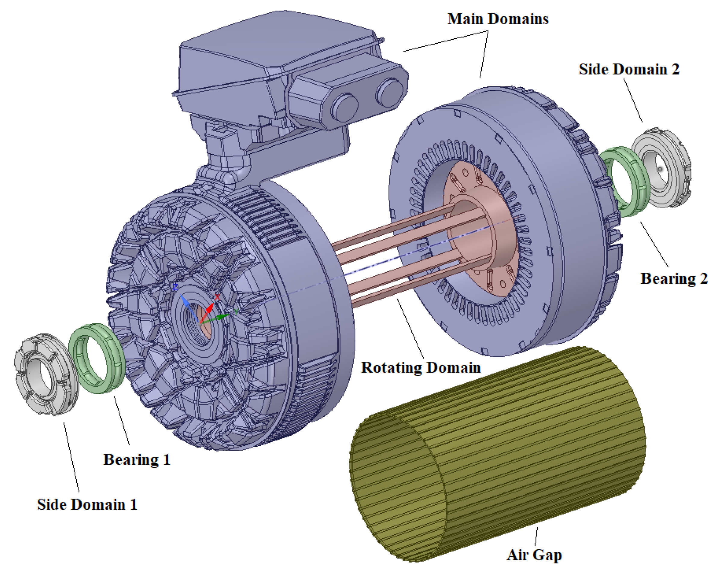
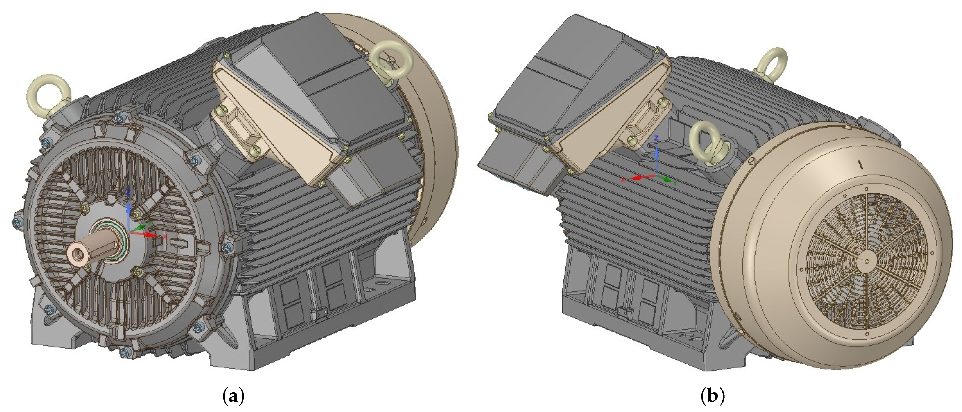
In our research described in this paper, an induction motor with a nominal power of 315 kW, nominal speed of 2987 rpm, and weight of approximately 1400 kg provided by Siemens, s.r.o. Elektromotory Frenstat has been used. The 3D model of this motor is shown in Figure 1. The CAD model contained up to 150 parts excluding electrical windings and slot liners. The complete motor structure is made of cast iron. Terminal box (D) consists of three parts connected by bolts, including a terminal plate. The stator core (K) is connected to the motor frame (C) by an overlap fit. It is made up of hundreds of steel sheets. The regular air gap pattern around the stator assembly perimeter is formed by technological processes. Forty-eight electrical winding packs (L) are embedded in the stator core, and they are separated from each other by slot liners. The rotor part consists of a rotor core (M), shaft (Q), and aluminium rotor cage (N). The rotor core is made up of hundreds of steel sheets. The two ball bearings (O) are mounted in the nondrive end-shield (G) and drive end-shield (B), and they are lubricated by bearing grease. Both bearings are sealed with a bearing cover (P) and shaft sealing ring (R). Both shields have internal and external cooling fins for better bearing heat transfer. A small fan wheel (I) is designed to reduce mechanical losses and high noise levels compared to the motor diameter. Because of bidirectional operation, it is designed with straight blades. It is covered by a fan cowl (J). The motor frame is equipped with a pair of holders (E) for easy handling. The inner region of the motor is filled by three domains: (1) main endcap air (V), (2) ball-bearing air (U), and (3) side ball-bearing air (T). The individual positions are shown in Figure 2.
The geometry was minimally simplified or modified to achieve the most accurate results. The bolt heads (S) were capped. The washers were united with bolts. The circlips were united with the shaft (Q). The electrical winding (L) was divided into two parts. The first embedded part contained a parallel arrangement of individual wires. The second torus part contained a circular arrangement of individual wires. In both cases, individual wires were replaced by a solid domain. Slot liners consisting of PET film were neglected. The air gaps between the stator assembly (K) and the finned frame (C) were neglected. The size of the air gap between the stator assembly (K) and rotor assembly (M) so-called rotor–stator air gap was relatively large so it was included in a simulation. The fan cowl (J) was made of plastic, and the contact surface between the motor frame and the fan cowl was small; therefore, the fan cowl was neglected in the FEM simulation only.
The individual parts were precisely moulded together to achieve the correct contact interface between them. For this reason, access to the interior of the motor body was only possible through one small air hole drilled in the rear end shield. Assuming that it is neglected, it is possible to solve the internal and external air-flow velocity independently of each other and thus also significantly reduce the time-consuming task.

3. Theoretical Background

3.1. Convective Heat Transfer Model between Frame and Ambient

An essential parameter for an adequate FEM model is correctly determining the air-flow velocity profile around the motor, especially between fins. Without the CFD approach, predicting the air-flow velocity profile around the motor fins is not easy. Many papers deal with the thermal distribution in a specific motor, but fewer with the flow around the fins, and the results are generalized. Many measurements are necessary to determine generalized empirical formula, which is complicated because, in an induction motor, many fin channels outside the body are obstructed by terminal boxes, bolt lugs, and cables. An example of a paper dealing with an empirical expression of the air-flow velocity profile for the induction motor surface is Klimenta [3]. His equation is expressed in the form (1).
v ( y ) = C 1 · V 0 · [ 1 Θ 0 · ( y / L 5 ) 2 + 0.5 · Θ 0 · ( y / L 5 ) 4 ] .
where the constant C 1 [-] depends only on the airflow conditions, it defines the rate of deceleration of the air velocity depending on the size and number of obstructions behind the fan cowl. For example, for C 1 = 1 in the calculation, the effect of the obstructions is negligible; for C 1 = 2/3 in the calculation, the effect of the obstructions is significant. V 0 [m/s] is the initial velocity at the fan outlet. L 5 [m] is the average fin length and y [m] is the longitudinal distance from the fan cowl and Θ [ ] is an expression defined by other constants.
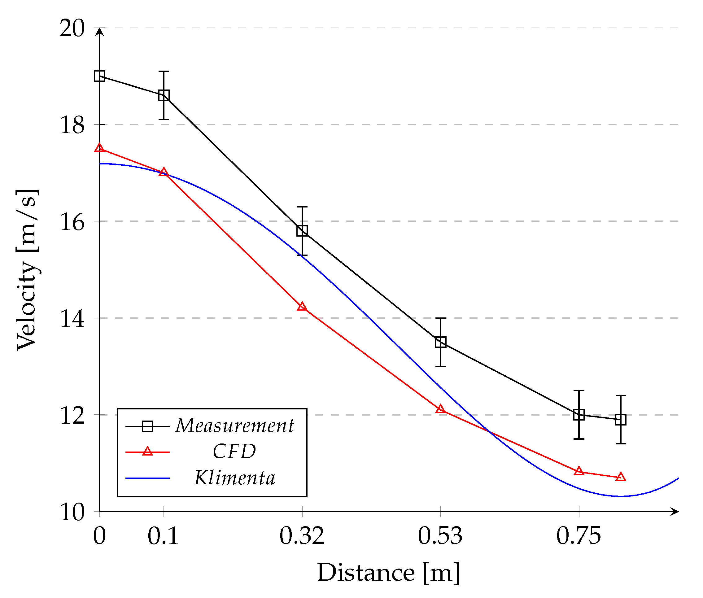
The clarification of this formula (1) is not the subject of this paper, but its application can be found in the paper written by Gebauer et al. [7]. You can find out that the most problematic constant is C 2 , which determines the slope of the curve. Unfortunately, this can only be determined by experiment or by estimating it from another geometrically similar motor. Klimenta [3] formulated the expression for determining the airflow velocity profile, which is valid for small motors up to approximately 15 kW. Based on his comparisons, it was found that: (1) the coefficient C 2 amounts to 1500 [m·rpm], and (2) that the values of the coefficient C 3 are: C 3 = 3 for p ≤ 4 and P ≤ 15 kW, C 3 = 2 for p ≤ 4 and P > 15 kW and C 3 = 8/3 for p > 4 and P∀. This was in satisfactory agreement with most of the experimental data. The quantity P = 15 kW, which corresponds to the change in the value of the C 3 factor, also coincides with the fact that induction motors rated up to 15 kW usually have an aluminium frame. In comparison, motors rated above 15 kW have a frame made of cast iron [8]. The results show that the empirical formula is flexible. The velocity profile along the fin can be fitted by an appropriate combination of C 1 , C 2 , and C 3 . Generally, all three constants can be determined by CFD simulation and/or experimental measurement. Figure 3 shows the typical air-flow velocity profile obtained from CFD simulation, experimental measurement, and analytical approach for our investigated induction motor.
The air-flow velocity profile obtained from the CFD approach, Figure 3, is applied to the Heiles analytical relation (2) to calculate the heat transfer coefficient at the motor surface between fins [4,9]. It determines the resulting temperature distribution in the motor body as a reaction to generated heat. Several authors have studied the determination of the HTC between the fins of an induction motor. Other relationships can be found in [10,11].
H T C ( v , f ) = f ( y ) · ρ · C p · D · v ( y ) 4 · L · ( 1 e m ) .
where H T C [W/m 2 K] is the heat transfer coefficient as a function of axial distance, f [-] is the turbulence factor which is discussed in Section 3.2, ρ [kg/m 3 ] is the density of air, C p [J/kgK] is the specific heat capacity of air, D [m] is the hydraulic diameter, v ( y ) [m/s] is air-flow velocity, L [m] is the axial length of cooling fins, λ [W/mK] is the thermal conductivity of air, and m [-] is defined in the form (3).
m ( y ) = 0.1448 · L 0.96 D 1.16 · λ ρ · C p · v ( y ) 0.214 .
where the hydraulic diameter is defined in the form (4).
D = 4 · S O .
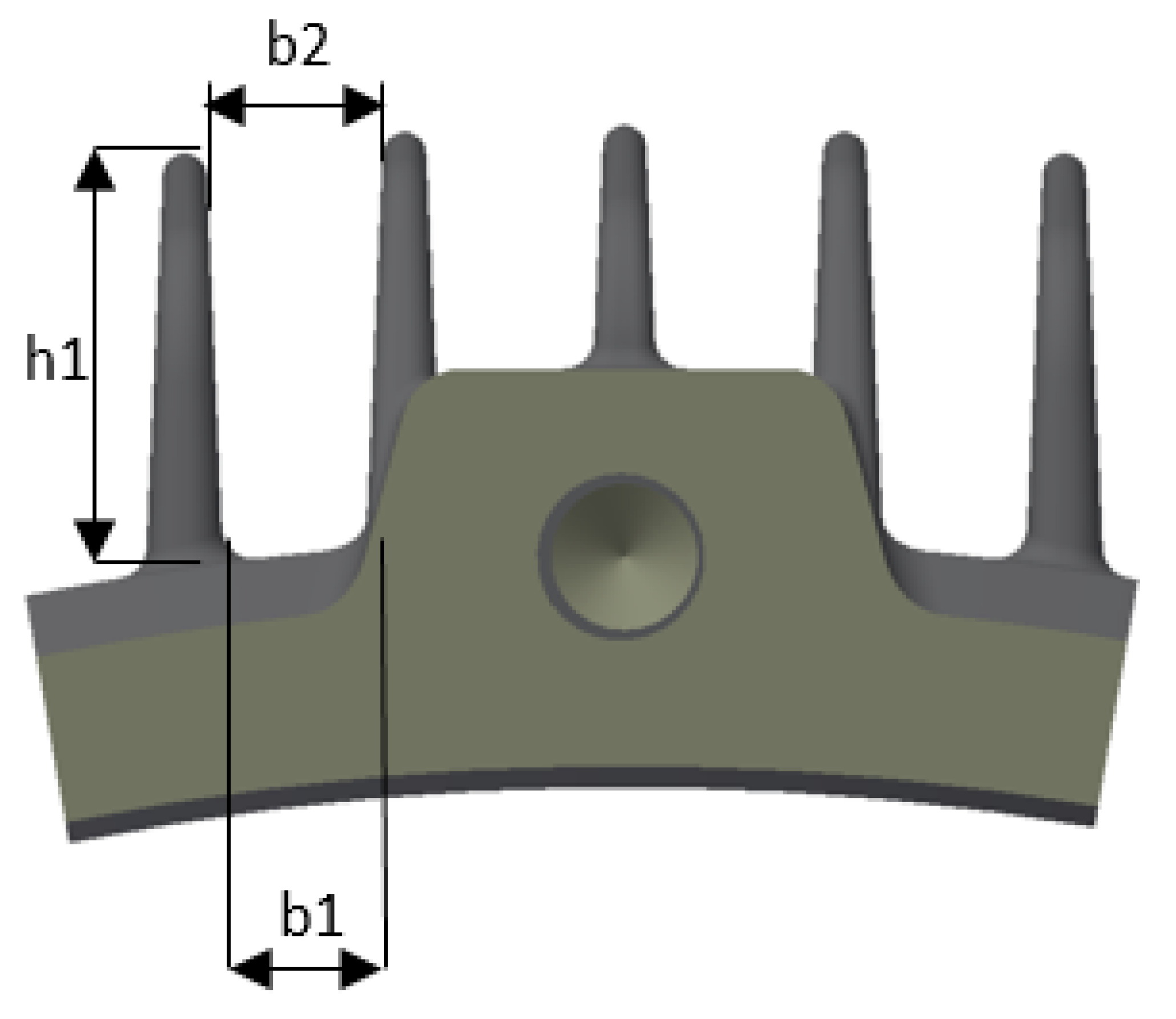
where S [m 2 ] is area of space between fins (5) and O [m] is wetted perimeter (6). Dimensions of the fin are shown in Figure 4. The application of the Heiles formula will be discussed in a later chapter on our investigated motor.
S = ( ( b 1 + b 2 ) · h 1 ) 2 .
O = 2 · h 1 + b 1 + b 2 .
Many authors assume a constant heat transfer coefficient (HTC) calculated from Heiles’s relation (2), such as [12,13]. Other authors have many simplifying assumptions that they include in their simulations. For example, no heat flow from the rotor core to the shaft [14], simplified geometry of the frame [15], etc. These assumptions are sufficient under certain conditions, but if we want to find out a real heat distribution throughout the entire induction motor, we need a precise heat transfer coefficient (HTC) related to the air-flow velocity profile and turbulence factor.

3.2. Turbulence Factor Model

The second important parameter in the Heiles relation (2) is the turbulence factor. Every induction motor has a different value. Heiles determined the turbulence factor in the range 1.7–1.9 [4]. However, the turbulence factor determined by Heiles mostly occurs at the beginning of the exit from the fan cowl, but further downstream may not be in this interval. This issue was studied by O. Klimenta and A. Hannukainen [3], they proposed a general relation of the turbulence factor depending on the longitudinal coordinate from the leading edge of the fin (7).
K ξ , y = K 1 + ( K 2 K 1 ) · e K 3 · y .
where K 1 [ ] is a coefficient representing the minimum value of the turbulence factor at a long distance from the fan cowl ( y ) , K 2 [ ] is a coefficient representing the maximum value of the turbulence factor at zero distance from the fan cowl ( y = 0 ) and K 3 [m 1 ] is a coefficient which describes the reduction of the turbulence factor.
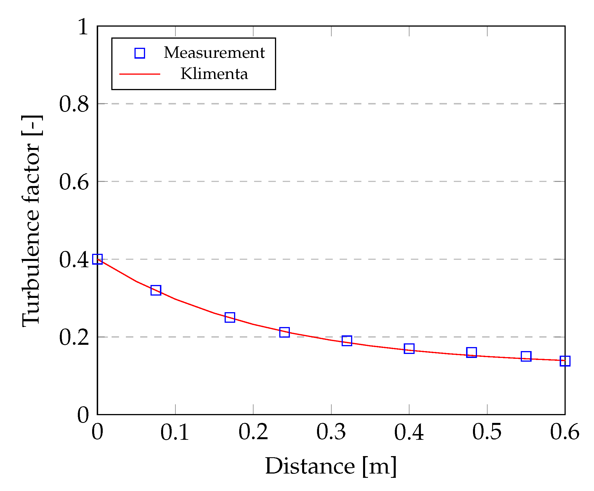
As shown in Figure 5, the turbulence factor is in the interval from 0.4 to 0.122, which is much less than Heiles determined. The solid curve coincides well with the experimental data represented by the square markers; therefore, the turbulence factor can be estimated using expression (7).
The authors have expressed three relationships that apply to the motor power range of 4–15 kW. The first relationship (8) is for flat outer surfaces of end-shields. The second relationship (9) is for cylindrical outer surfaces of end-shields. The third relationship (10) is for fins and interfin surfaces.
K ξ , y = 1 + ( 1.4163 1 ) · e 4.62 · y .
K ξ , y = 1 + ( 1.6776 1 ) · e 13.087 · y .
K ξ , y = 1 + ( 1.8 1 ) · e 13.087 · y .
The objective of this paper is not to reproduce the process by which they reached their final expressions but only to determine their possible application. The question is whether relation (7) or relations (8)–(10) apply to our investigated induction motor, and if so, which values of the turbulence factor are relevant.

3.3. Heat Transfer Model for the End-Shield

Due to the rotational motion of the rotor and its parts, air flows tangentially around the end-shield area. It is, therefore, viable to consider forced convection as flow over a flat plate. Chapman derived relations (11) and (12) for both types of flow, which can be found in [16,17].
N u = 0.664 · R e 1 / 2 · P r 1 / 3 f o r l a m i n a r f l o w .
N u = 0.036 · R e 0.8 · P r 1 / 3 f o r t u r b u l e n t f l o w .
where Reynold number R e [ ] is in form (13) and Prandtl number P r is in form (14).
R e = ρ · v a v e · H s h μ .
P r = c p · μ λ .
where ρ [kg/m 3 ] is the air density, v a v e [m/s] is the average air velocity, H s h [m] is the distance of the shaft center from the base, μ [Pa · s] is the air dynamic viscosity, c p [J/kgK] is the air specific heat capacity, and λ [W/mK] is the thermal conductivity of air.
H T C = N u · λ r .
The heat transfer on the end-shield wall is then determined by the heat transfer coefficient H T C [W/m 2 K] given by the Nusselt number and the radius r [m] of the end-shield (15).
The application of the relations (11) or (12) will be shown and discussed in a later section using the motor under investigation.

3.4. Convective Heat Transfer Model for the Air Gap

The exact determination of the drag moment due to air friction in the rotor–stator air gap and on the rotor blades is crucial for specifying the internal mechanical losses. Generally, if the air gap decreases, the friction moment increases, and the heat transfer between the stator and rotor decreases and vice versa. There is little or no axial heat flow from the air gap into the end-cap air. The heat emitted from the rotor surface is assumed to be transferred directly across the air gap to the stator.
This phenomenon was investigated by Taylor, who derived relations for the so-called Taylor vortex development. The air gap of the machine is modelled by a smooth inner rotating cylinder and a grooved stationary surface. On the base of the Taylor, the number can be calculated as the Nusselt number, which is necessary for the specification of the heat transfer coefficient (16). The Equation (17) expresses the dimensionless Taylor number as a function of the Reynolds number (18).
N u = ( H T C / λ a i r ) · l g .
T a = R e · ( l g / R r ) 0.5 .
R e = ( ρ · ω · R r · l g ) / μ .
where H T C [W/m 2 K] is a heat transfer coefficient, λ [W/mK] is a thermal conductivity of an air, l g [m] is an air gap radial lenght, R r [m] is radius of a rotor, ω [1/s] is angular velocity of a rotor, and μ [Pa · s] is a dynamic viscosity of an air.
Taylor identified three possible regimes that can occur [16,18,19]. If T a < 41, the flow regime is laminar and heat transfer is due to the thermal conduction of air only. If 41 < T a < 100, there is a transitional flow region with enhanced heat transfer in the vortex. If T a > 100, the flow regime is turbulent, and turbulent heat transfer is dominating, Table 1.
In this case, the determination of the heat transfer coefficient (16) was not used because the air gap was simulated directly as a part of internal CFD simulation. The air gap was substituted as a solid thin layer with higher thermal conductivity in FEM analysis. The methodology for tuning the thermal conductivity is explained in Section 7.3.

3.5. Heat Transfer Model between end Windings and Endcap Air

Stator winding usually consists of a number of similar coils placed in sequential slots in the stator surface and connected in series. The end-winding is composed of individual coils into a single package glued together by some impregnation. The end-windings are typically the hottest and the most critical part of an induction motor. Therefore, precise determination of the temperature at its centre is important.
In fact, the end-winding cooling is due to forced convection on all wire surfaces. Unfortunately, applying HTC on every wire in the coil is not realistic. For this reason, a simplifying assumption was made to model the end-winding as a single solid in the form of an anuloid with an orthotropic material model. Then, forced convection can be applied to all anuloid surfaces.
Convection cooling depends on many factors, e.g., the shape of the end-winding, number of the blades on the rotor cage, and the shape and complexity of the end-shield. Several authors have studied such cooling of an anuloid [1,20]. The formula for general use was defined in the form (19).
H T C = k 1 · [ 1 + k 2 · ( v ) k 3 ] .
where v [m/s] is the speed of air around end-windings, k 1 [ ] characterizes natural convection, k 2 [ ] and k 3 [ ] characterize forced convection and H T C [W/m 2 K] is the average convective heat transfer coefficient. The value of individual coefficients, according to the authors, is given in Table 2.
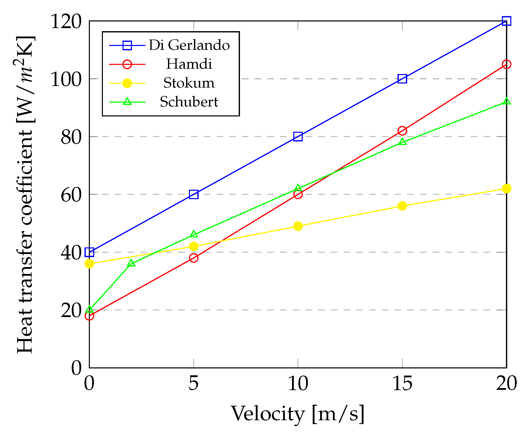
Figure 6 shows randomly selected theories according to the authors. It can be seen that the heat transfer coefficient increases with increasing flow velocity. It is reassuring that all the curves show the same trends.
However, because of the complicated geometry of the end shields and the interdependence with the air endcap, Equation (19) is inadequate for simulating the internal domain. This approach perfectly suits the lumped parameter thermal model [25,26].
The relationship between skin friction and heat transfer is generally known. From an engineering point of view, calculating skin friction is useful in estimating the total frictional drag exerted on an object and the convectional heat transfer rate on its surface [27]. This relationship is well developed in the concept of Reynolds analogy. The Reynolds Analogy is popularly known to relate turbulent momentum and heat transfer [28]. That is because in a turbulent flow (in a pipe or in a boundary layer) the transport of momentum and heat transport dominantly depends on the same turbulent eddies: the velocity and the temperature profiles have the same shape.
This knowledge showed us that similar behavior could be achieved between the shear strain rate and thermal contact conductivity, HTC, respectively. Figure 6 shows that there is a linear relationship between air velocity and HTC. That is why we had to ask: is it possible to have a linear behaviour between the shear strain rate and the thermal contact conductivity of a separated domain (for example, between end-winding and endcap air)?
The new heat transfer contact approach will be explained directly on the investigated induction motor in Section 7.4.

3.6. Heat Transfer Model for Other Surfaces

Terminal box, bolt heads, washers, holders, motor feet surfaces, etc. HTC needed to be specified according to the character of the flow. The two fundamental types of flow exist: (1) flow parallel to the wall and (2) flow perpendicular to the wall. HTC for flow parallel to the wall is defined by the formula (20) and (21) [29].
H T C p a r = 2 · λ a i r L p a r · 0.3387 · P r 1 / 3 · R e L 1 / 2 ( 1 + ( 0.0468 / P r ) 2 / 3 ) 1 / 4 i f R e L 5 · 10 5 .
H T C p a r = 2 · λ a i r L p a r · P r 1 / 3 · ( 0.037 · R e L 4 / 5 871 ) i f R e L > 5 · 10 5 .
where λ [W/mK] is a thermal conductivity of air, L p a r [m] is wall length, P r is Prandtl’s number defined by (14), and R e L is Reynold’s number defined by (22).
R e L = v · L p a r / η .
where η [m 2 /s] is a kinematic viscosity.
The HTC formulas for rotating cylinders, annuli, and spheres have been defined in [30,31]. The HTC on the shaft surface was defined by using the formula (23)–(25).
H T C = ( N u · λ a i r ) / b .
N u = 0.022 · R e ψ 0.821 .
R e ψ = ( ρ · Ω · b 2 ) / μ .
where H T C [W/m 2 K] is a heat transfer coefficient for rotating wall, N u [ ] is the Nusselt number, λ [W/mK] is a thermal conductivity of an air, b [m] is radius of a rotor, R e ψ is the Reynolds number for rotating wall, Ω [rad/s] is angular velocity of a rotor, and μ [Pa · s] is a dynamic viscosity of an air.
An induction motor can contain many blind spaces such as air pockets inside the motor feet. An HTC of 5 [W/m 2 k] was applied to these surfaces.

4. Orthotropic Material Models

Induction motors are created from different variations of material types. For small dimensions and performance motors, its frame material is mostly aluminium alloys. Cast iron is used for motors of large dimensions and power outputs. The end shields are chosen in a similar way. Fan wheels and fan cowls are made of aluminium alloys or plastics. The shaft, bearings, screws, and others are made of steel. In terms of physical properties, all that materials are isotropic, and determining the material model is not a problem. Thermal conductivity, specific heat capacity, and density are constants given in material data sheets or tables. In contrast, the stator, rotor, and windings are a kind of composite of more than two materials. To reduce the computational time requirements, engineers deal with adequate analytical relationships describing reality in the form of orthotropic material models.
One of the researchers who dealt with this issue is Benion [32]. He dealt with the design of orthotropic material for stator and rotor lamination stack. The stator (rotor) consists of a steel sheet of certain magnetic properties stacked on top of each other with a thin layer of insulating coating between them. Motor lamination thermal conductivity is defined in the form (26).
λ y = R c t + 1 λ L 1 .
where λ y [W/mK] is the through-stack thermal conductivity, R c [m 2 K/W] is the interlamination thermal contact resistance, λ L [W/mK] is the lamination thermal conductivity, and t [m] is the thickness of the steel sheet. The developed model for lamination thermal contact resistance to enable estimates of through-stack thermal conductivity for new materials is defined in the form (27).
R c = ( 1.53 · σ R M S ( P / H ) 0.097 + t C 5 ) / λ a i r .
where σ R M S [m] is the surface roughness of contacting surfaces, P [Pa] is the contact pressure, H [Pa] is the surface microhardness, t C 5 [m] is the lamination coating thickness, and λ a i r 55 [W/mK] is the air thermal conductivity at 55 °C.
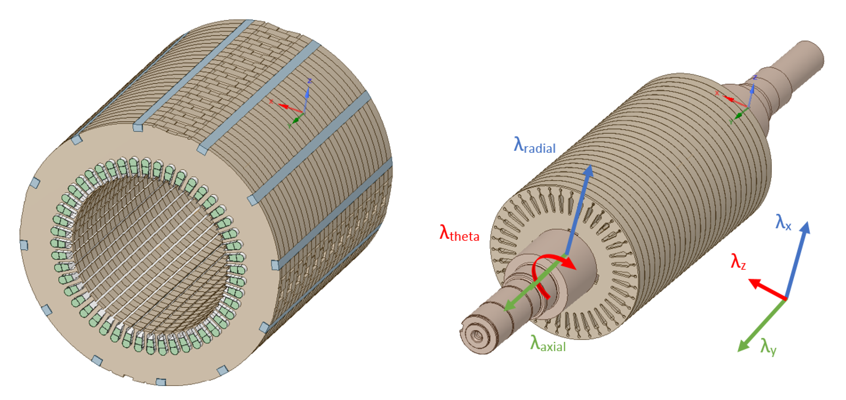
The through-stack thermal conductivity is λ y = 1.52 [W/mK] for our motor under investigation. The thermal conductivity in the x and z direction was left at λ x = λ z = 36 [W/mK]. Thermal conductivity values can also be transformed to the cylindrical coordinate system λ y = λ a x i a l , λ x = λ r a d i a l and λ z = λ t h e t a . The transformation from the Cartesian coordinate system to the cylindrical coordinate system is shown in Figure 7. The density and specific heat capacity were left unchanged because the volume ratio of the lamination coating thickness to the steel lamination stack is negligible. All lamination constants for the motor are summarized in Table 3.
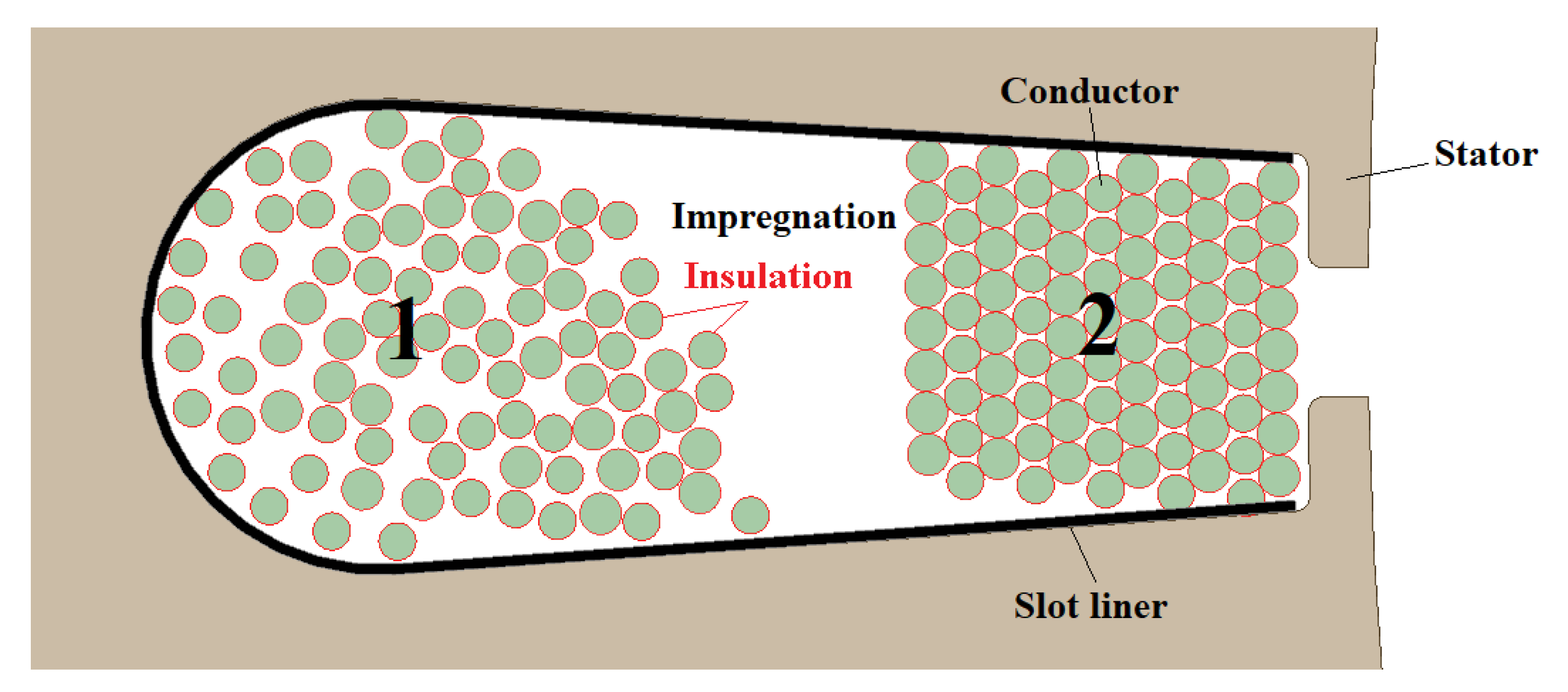
An electrical winding typically contains three materials: the conductor material, the impregnation material, and the conductor insulation material. A typical wire arrangement in the stator groove is shown in Figure 8. Ideally, the wires are arranged according to region 2, but the reality is shown by region 1.
The analytical approximation for estimating thermal conductivity for winding according to the authors Hashin and Shtrinkman [33,34] was used. The expression (28) has been proposed by a number of authors in various forms [35,36,37,38,39], and it is successfully applied to electrical winding homogenization in [40].
λ e = λ a · ( 1 + υ c u ) · λ c u + ( 1 υ c u ) · λ a ( 1 υ c u ) · λ c u + ( 1 + υ c u ) · λ a .
where λ e [W/mK] is the equivalent thermal conductivity, λ a [W/mK] is the equivalent thermal conductivity of the insulation amalgam, which is defined in form (29), υ c u [ ] is the volume ratio of conductor and it is taken to be equal to the packing factor P F , λ c u [W/mK] is the thermal conductivity of conductor.
λ a = λ i i · υ i i υ i i + υ c i + λ c i · υ c i υ i i + υ c i .
where λ i i [W/mK] is the thermal conductivity of impregnation insulation, λ c i [W/mK] is the thermal conductivity of conductor insulation, υ i i [ ] is the volume ratio of impregnation insulation, υ c i [ ] is the volume ratio of conductor insulation. The relationships between the packing factor, total volume, impregnation volume, conductor volume, and conductor insulation volume are given by (30)–(34) for a round conductor in which r c [m] and l i [m] are the conductor radius and the insulation thickness, respectively.
P F = υ c u + υ c i .
1 = υ c u + υ c i + υ i i .
υ i i = 1 P F .
υ c u = P F · r c 2 ( r c + l i ) 2 .
υ c i = P F · ( 2 · r c · l i ) + l i 2 ( r c + l i ) 2 .
It is important to mention that the approximation is formulated only for the cylindrical shape of conductors and does not apply to general conductor profiles. The two-step homogenization requires reformulation if the conductor profile is changed. Material properties of winding are shown in Table 4.
The equivalent density (35) and the equivalent specific heat capacity (36) were calculated according to [41]. The air’s density and specific heat capacity were neglected due to the complete filling of the stator slot with impregnation. Expression (35) or (36) can be used analytically to calculate λ a x i a l if we substitute them for the thermal conductivity of each material.
ρ e = ρ c u · υ c u + ρ c i · υ c i + ρ i i · υ i i + ρ a i r · υ a i r .
C p e = C p , c u · υ c u + C p , c i · υ c i + C p , i i · υ i i + C p , a i r · υ a i r .
where ρ e [kg/m 3 ] is the equivalent density, C p e [J/kgK] is the equivalent specific heat capacity, υ c u [ ] is the volume ratio of conductor, υ i i [ ] is the volume ratio of impregnation insulation, υ c i [ ] is the volume ratio of conductor insulation, υ a i r [ ] is the volume ratio of the air.
The equivalent material properties of electrical winding are shown in Table 5.
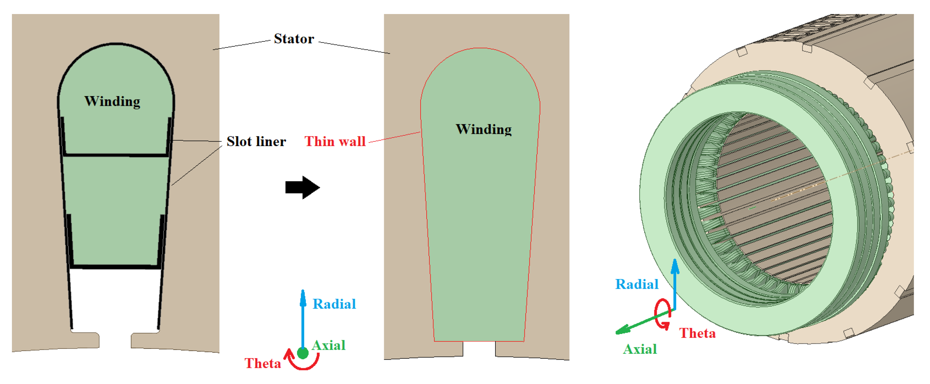
The equivalent thermal conductivity can be transformed from a cartesian coordinate system to a cylindrical coordinate system. However, the electrical winding geometry had to be changed first. Figure 9 shows the before and after modifications. The slot liner was removed. Instead, it was simulated by a thin wall. The stator slot was filled by electrical winding.
The orthotropic thermal conductivity setting for the stator slot is as follows: λ e = λ r a d i a l = λ t h e t a and λ a x i a l = λ a x i a l . The orthotropic thermal conductivity setting for the end-winding is as follows: λ e = λ r a d i a l = λ a x i a l and λ a x i a l = λ t h e t a .
The temperature of the induction motor was measured in a laboratory chamber with an ambient temperature of 20.2 °C. The thermal parameters for the external air domains were set as follows: air density ρ 20 = 1.188 [kg/m 3 ]; dynamic viscosity μ 20 = 1.831 × 10 5
[Pa · s]; thermal conductivity λ 20 = 0.0262 [W/mK]. An air temperature assumption of 60 °C was chosen for the internal air domains. The values for the internal air were set as follows: air density ρ 60 = 1.046 [kg/m 3 ]; dynamic viscosity μ 60 = 2.01 × 10 5 [Pa · s]; thermal conductivity λ 60 = 0.0282 [W/mK].
Material properties of the individual parts are summarized in Table 6.

5. Induction Motor Looses

The power loss in electric motors can be divided into four groups according to the characteristics of its generation [25,42,43,44].
(1) Iron losses. The main losses are divided into hysteretic losses and eddy current losses. These losses are due to the properties of the magnetic material that is used. Eddy current losses are greatly affected by the area over which the currents can close. Hysteretic losses are due to the overmagnetization of the material. Additional losses in the iron are due to magnetic field oscillations caused by the effect of air gap nonuniformity caused by slots.
(2) Electrical losses. Electrical losses are also called Joule losses. The current passing through the stator or rotor conductor generates Joule heat. Electrical losses make up the majority of the total losses in most motors.
(3) Mechanical losses. These are caused by mechanical friction and aerodynamic drag. This includes the bearings and the fan wheel.
(4) Additional losses. These losses include those produced by vibration and acoustics but are mostly due to dissipative magnetic fluxes and higher harmonic fluxes.
Measurements of the motor losses were performed in an equipped Siemens laboratory chamber. Measuring and calculation of efficiency were in accordance with IEC/EN 60034-2-1:ED.2-14. The basic test condition was: (1) The ambient temperature was 20.2 °C. (2) The load test condition was set to 100%, which corresponds to 315 kW of motor power. (3) The angular velocity was 2987 [1/min]. (4) The operating temperature of the motor was reached.
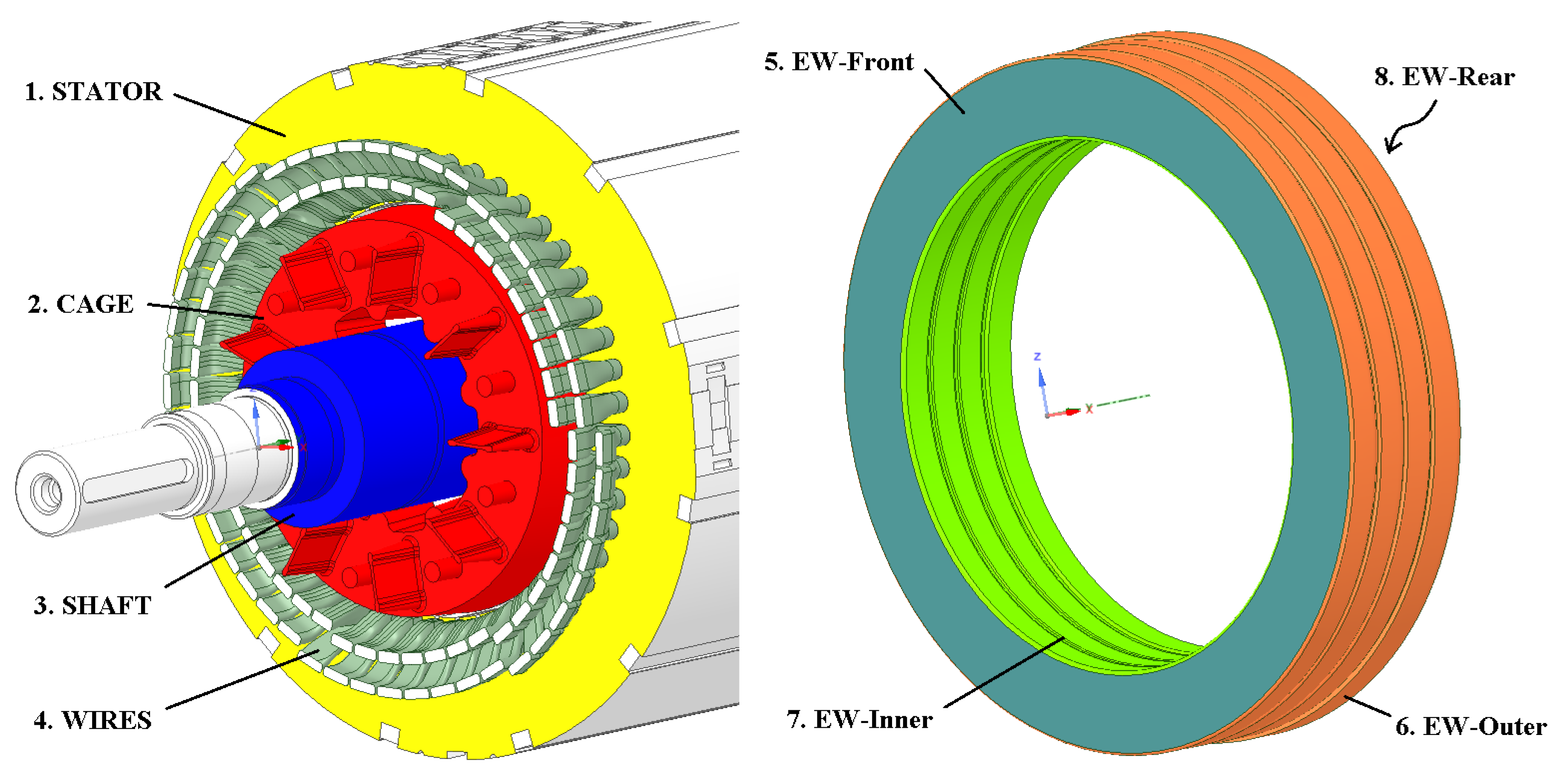
Siemens laboratory provided a summary report of the measured loss values, which were applied to the conjugate heat transfer (CHT) model with respect to the solid domains.
The total value of the iron losses was 3972 W. It was divided between the rotor and the stator domain in the 1185 W to 2786 W ratio (see Figure 10).
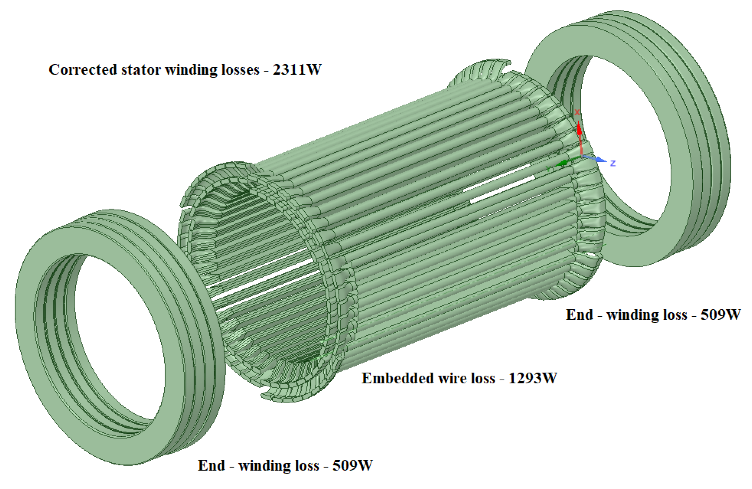
The corrected stator winding losses was 2311 W. The loss distribution for the embedded wires inside the stator was 1293 W and 509 W for each end-winding (see Figure 11).
The corrected rotor winding loss was 1365 W. The loss distribution for the cage wires inside the rotor was 1293 W and 763 W for each short circuit rings (see Figure 12).
Mechanical losses are more difficult to define. According to the report, the sum of all these losses was 1870 W. These had to be divided among the external loss (fan wheel), internal loss (rotor), and frictional loss (ball bearing). Only the frictional loss must be determined for CFD and FEM simulation. Two approaches in [7] give the procedure for evaluating mechanical losses. Frictional losses of 360 W were estimated for both ball bearings.

6. Conjungate Heat Transfer Model of Induction Motor

Using the HPC infrastructure available at IT4Innovations, CFD simulations can be performed for the complete induction motor without significant shape simplifications. According to the presented approach, a virtual numerical model can partially replace experimental measurements. It allows for accelerating the process of fan section design and can estimate the impact of each modification on the parameters of the induction motor without the production of the physical prototype.
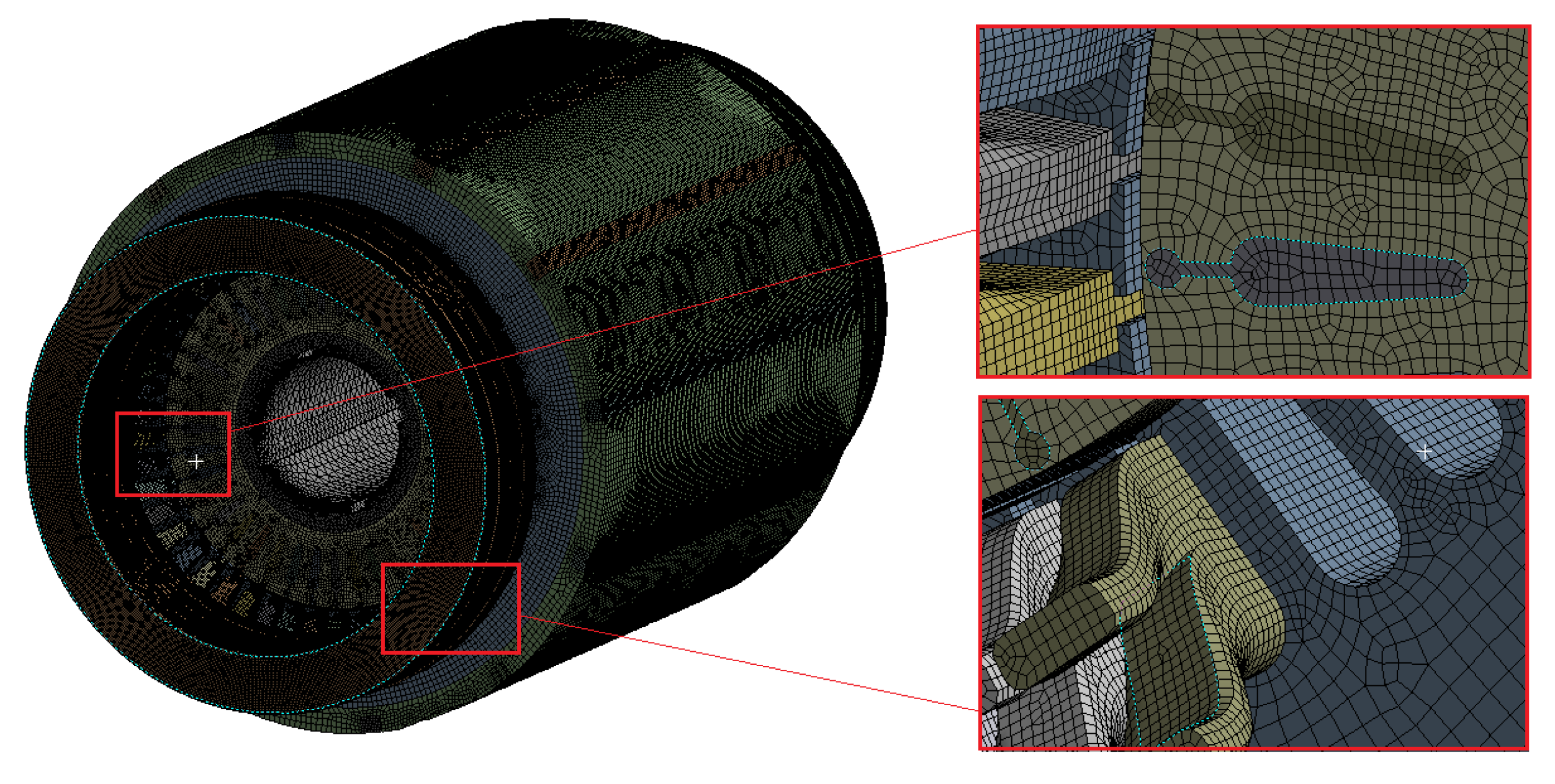
The final numerical conjugate heat transfer model (CHT)-contained a total of 49 fluid and solid domains that were connected by 109 defined interfaces. The total number of elements was approxiamtely 240 million. The external fluid domain contained 130 million elements, the internal fluid domain contained 73 million elements, and the solid domain contained 35 million elements. The boundary layer contained 10–15 elements at a 2–2.5 mm thickness for all fluid domains except the air gap between the rotor and stator. There were 25 elements, and a mapped mesh was created. Figure 13 shows a cross-section through the fins and air gap of the computational mesh.
The external fluid model contained one stationary and two rotating domains. The stationary domain consisted of multiple regions that were interconnected by a conformal mesh. The elements became smaller toward the motor body with each adjacent region. The dimensions of the stationary domain were modelled at a sufficient distance from the motor frame. The first rotating domain was created around the drive shaft extension and the second one around the fan wheel (see Figure 14). The open pressure boundary condition Opening Press. and Dirn = 0 [Pa] was applied at all outer walls of the stationary fluid domain except the bottom side. A No Slip Wall condition was applied. The Flow Direction was set to Normal to Boundary Condition.
The internal fluid model contained five stationary domains and three rotating domains (see Figure 15). Air gap domain was static, but the rotating wall condition was set to the side of the rotor surface. The grease inside the ball bearings was neglected.
The solid domains (stator, rotor, windings) were created primarily of hex element types. The stationary solid domains consisted of multiple regions that were interconnected by a conformal mesh (see Figure 16). The interface General Connection between fluid and solid domains was set.
Reynolds number outside and inside the motor is generally greater than 2300, so the turbulence model is also required to describe the fluid flow. According to the CFD theory [2,45], the two-equation eddy-viscosity turbulence model SST k- ω was chosen. The assumption of incompressible flow was considered. A CHT model using the already prepared external and internal fluid domains was set up. More relevant information was published in [7], including a grid convergence study.
The orthotropic material properties were applied according to Table 3 and Table 5 for windings, stator stack, and rotor stack. The remaining material properties were applied to the other parts of the induction motor according to Table 6. An assumption of an incompressible flow with constant air values at 20 °C was set for the external fluid domain and 60 °C for the internal fluid domain. According to [46], a thermal resistance of 200 [mm 2 K/W] was defined at the interface between the stator and the motor frame. The thermal resistance of 1000 [mm 2 K/W] between the motor frame and the floor was defined. The other thermal resistance was not applied. The thin wall with a thickness of 0.36 mm between the stator and the winding was defined. Total Source was chosen for losses according to Section 5.
It was impossible to run the transient analysis because the operating temperature of the induction motor was reached after approximately 4 h. So, steady-state analysis was chosen instead. The following preprocessing and solver settings were chosen; see Table 7 and Table 8. The analysis was launched on 432 cores. The total computational time was 400 h (approximately 16 days). This computational time included a job startup, mesh refinement in critical domains, change of mesh interfaces ( G G I 1 : 1 ) , and steady-state time. The memory requirement for the job was about 1900 GB RAM.
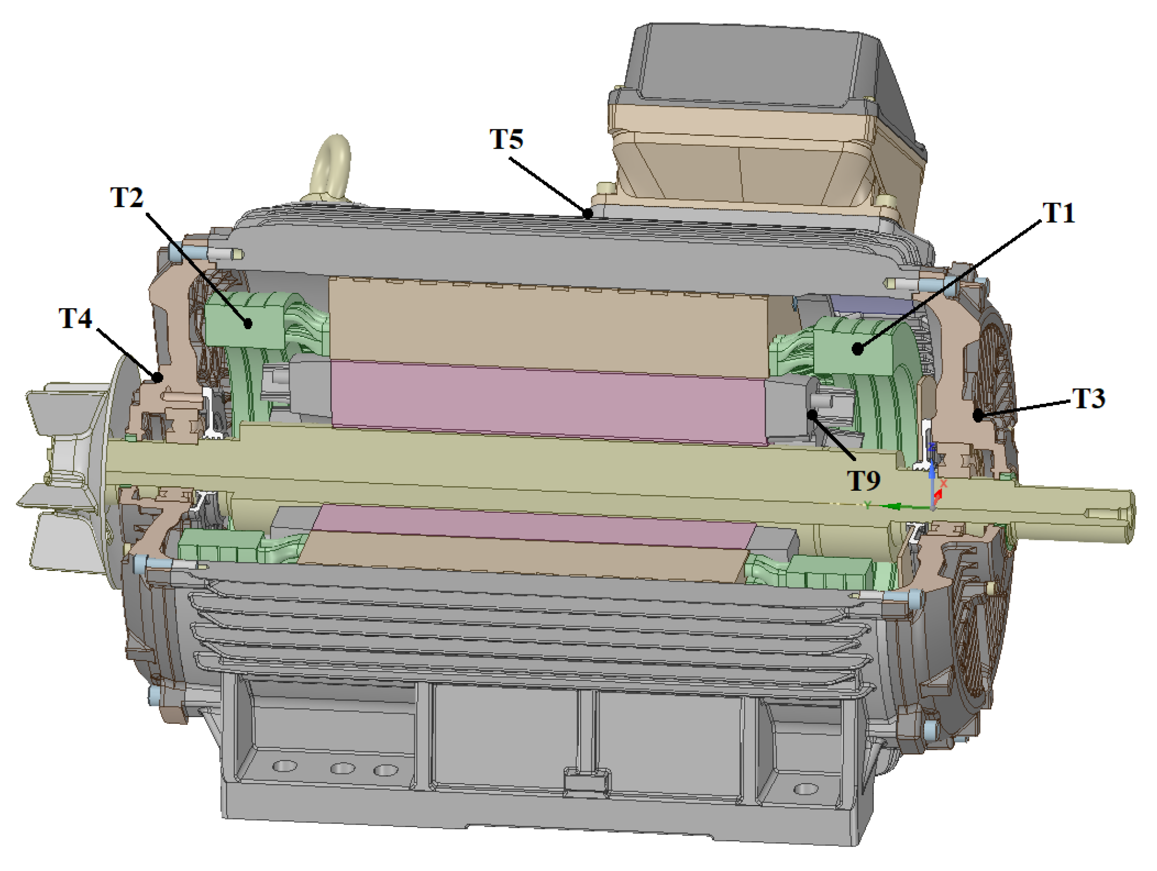
The most critical measuring points have been defined, as shown in Figure 17. The figure is for illustrative purposes only and can be used for all motor types. The description of the measuring points and their thermal values are given in Table 9.
The first pair of results (T1 and T2) shows the temperature inside the end-windings. It can be seen that the end-winding closer to the fan wheel is less thermally stressed than its more distant counterpart. Compared to the experimentally measured data, the difference is approximately 15 °C and approximately 30 °C higher. The inaccuracy in the simulation is due to several reasons: (1) Simplifying assumption of replacing the individual wire bundles with a single domain defined by the orthotropic material model; (2) incorrect input data for determining material constants for the orthotropic material model. In reality, the 3D model of the end-winding provided by Siemens does not correspond correctly to the volume fraction of a conductor and impregnation. The volume fraction in the end-windings was the same as that used in the wires located in the stator grooves; (3) the uniform end-winding geometry does not allow air to pass through the individual wire bundles and thus prevents cooling in its center; (4) the rotation direction of the coiled helix, which forms an imaginary anuloid, also plays a small role.
An important result is the ball-bearing temperature (T3). This bearing shows approximately 30 °C higher temperature than the bearing on the other side (T4). Ball-bearing life decreases significantly with a higher temperature; thus, its replacement becomes more frequent. It should be remembered that a higher temperature gradient also causes negative stress on other parts. Individual parts deform unevenly, which can affect higher noise level due to excited vibrations.
The temperature at the other measuring points corresponds to reality and needs no further comment.
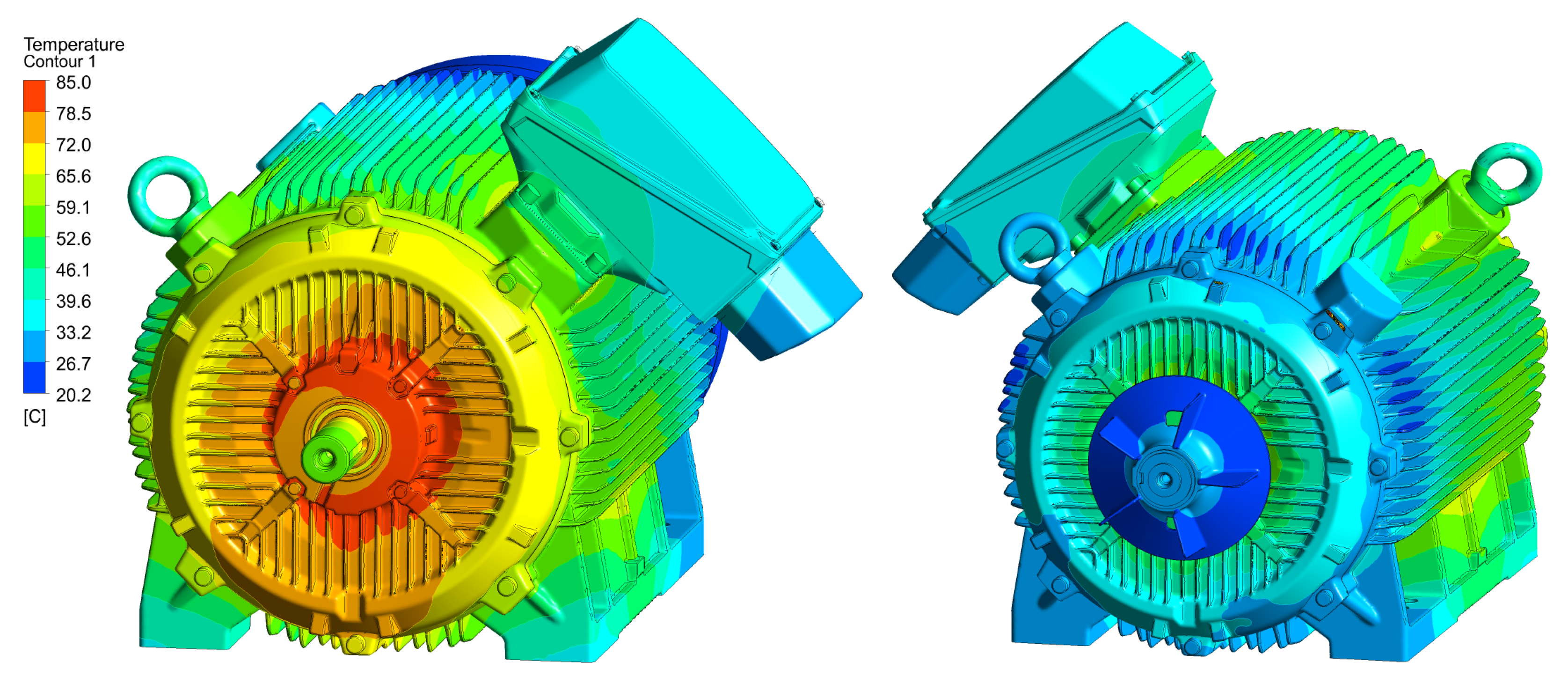
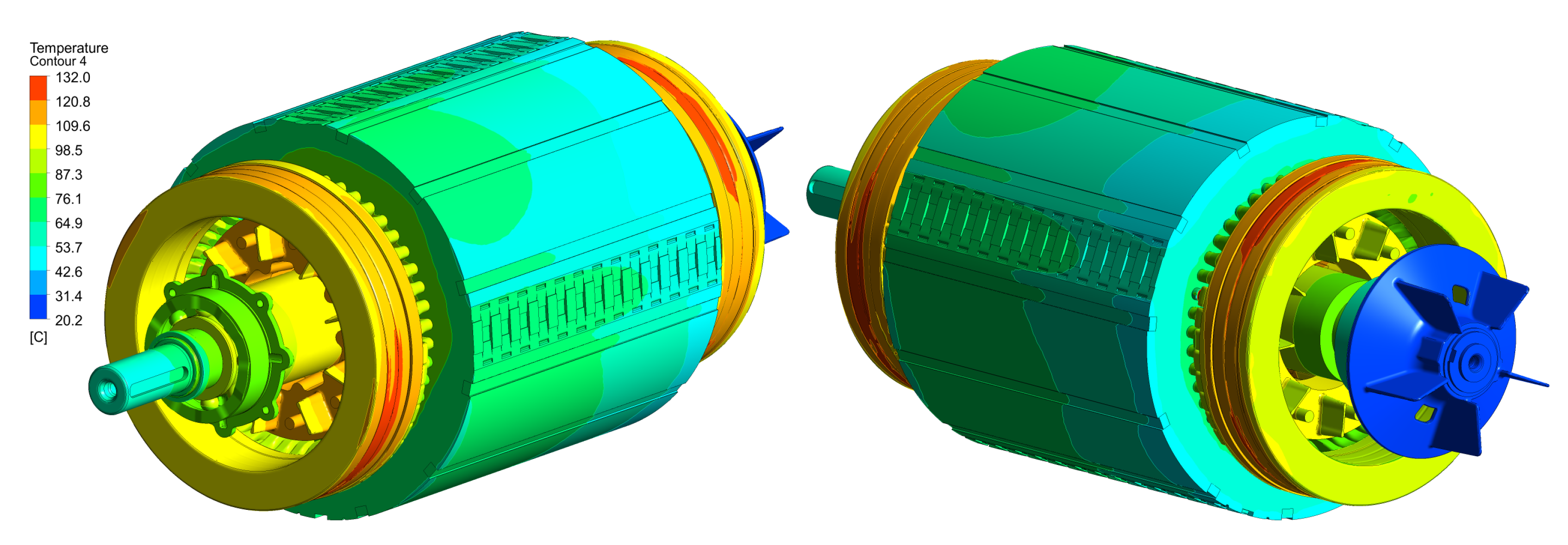
Figure 18 shows the temperature distribution on the motor surface. The temperature range is from 20.2 °C to 85 °C. It can be seen that the coldest place is the fan blades, which demonstrate the highest HTC values. On the other hand, the hottest place is the area near the ball bearing embedded in the drive end-shield. Figure 19 shows temperature distribution on the internal parts of the motor. The temperature range is from 20.2 °C to 132 °C. The hottest parts are the end windings, and the coldest one is the end of a shaft on the fan side.
The temperature results at the monitoring points are not sufficient to reliably verify the numerical model. Therefore, the temperature on its surface was also monitored. Thermal camera Flir P620 was used to measure the surface temperature of the investigated motor. It is a high-performance infrared camera that delivers accurate temperature measurements. The P620 includes a high-definition 640 × 480 infrared detector that delivers exceptional resolution and image quality for accurate infrared surveys. As a result, accurate readings can be taken on smaller objects at safe distances. Its detailed specifications are shown in Table 10.
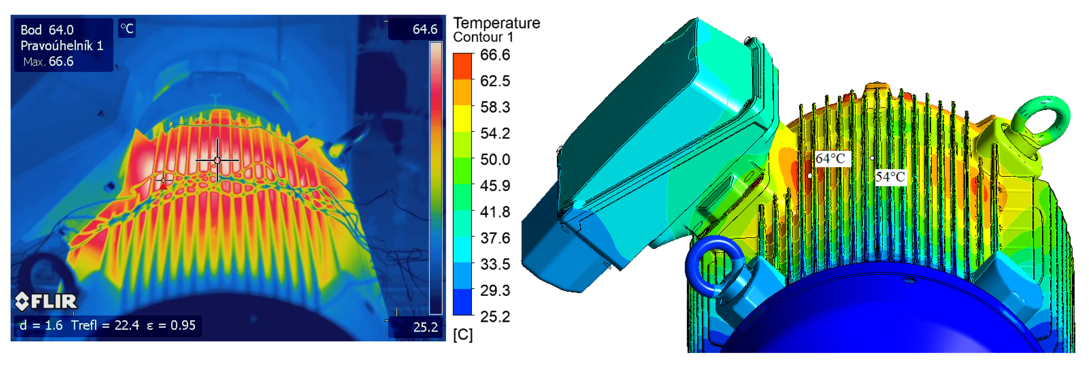
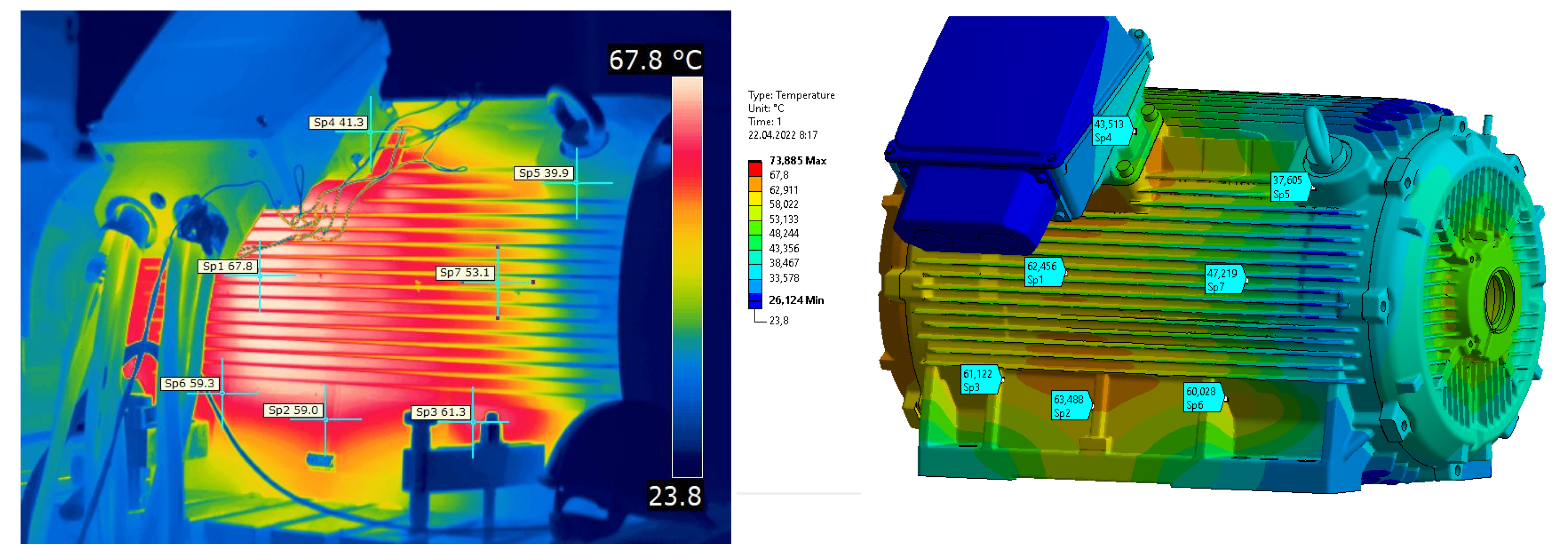
Figure 20 shows the first pair of temperature results on the left side of the induction motor. It can be seen that the CHT model shows a cooler region in the roughly central part of the motor. The temperature zone does not correspond, and the temperature difference is about 10 °C. The monitoring point of the thermal camera shows a temperature of 59.8 °C, whereas the CHT model shows 53 °C. The real temperature peak between fins is 67.4 °C and 55 °C for the CHT model.
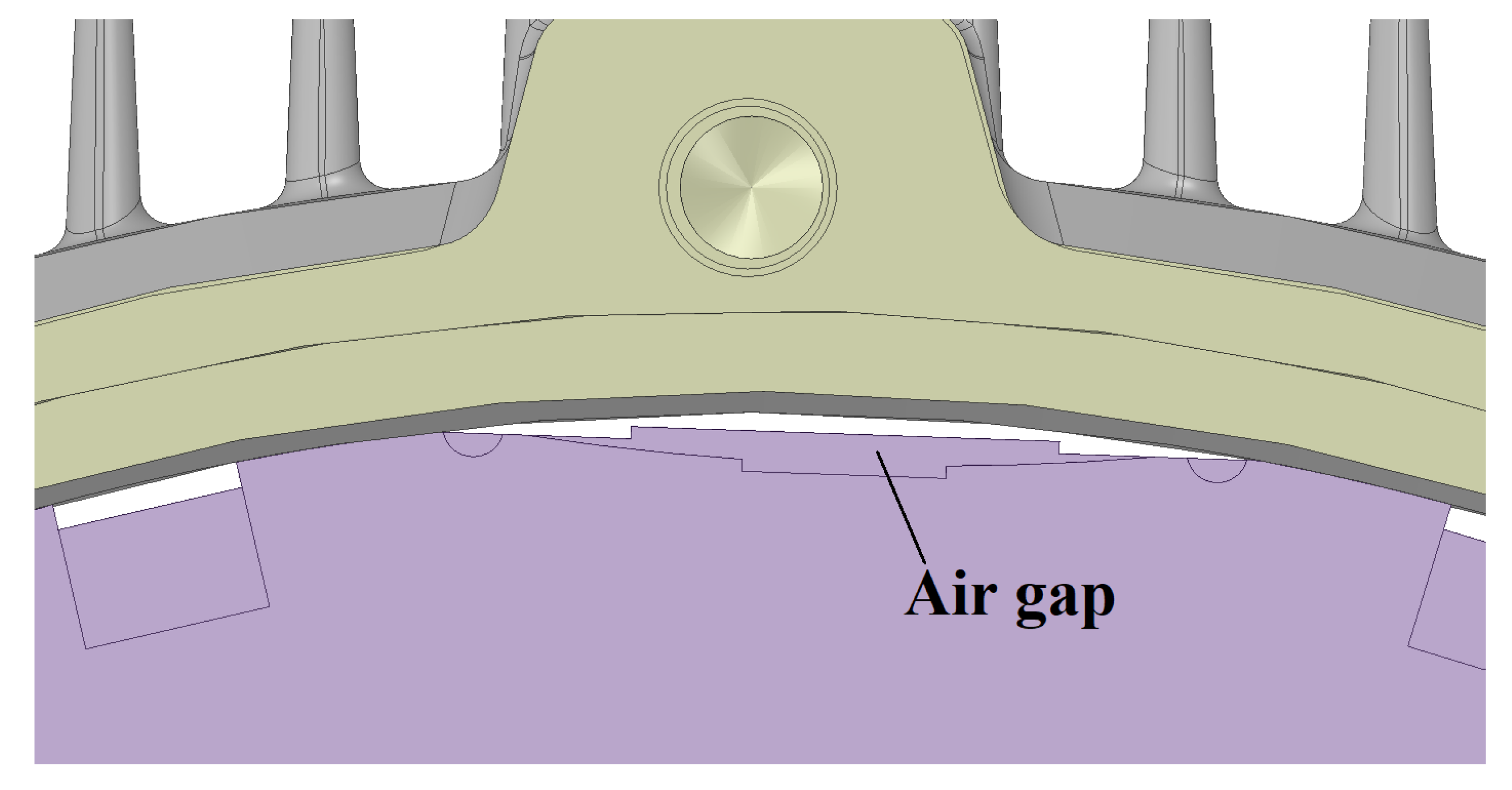
Due to the high complexity of CHT model preparation, these significant temperature differences were investigated by a simpler internal CHT model. The basic CHT model did not include a fluid domains which should be located between the motor frame and the stator. The four fluid domains were intentionally removed because of their shape complexity with respect to future high elements count. Figure 10 shows the rows of air pockets that were created by the technological workflow during the cutting of the stator plates. The air cavity thickness is 2 mm and contains many sharp edges.
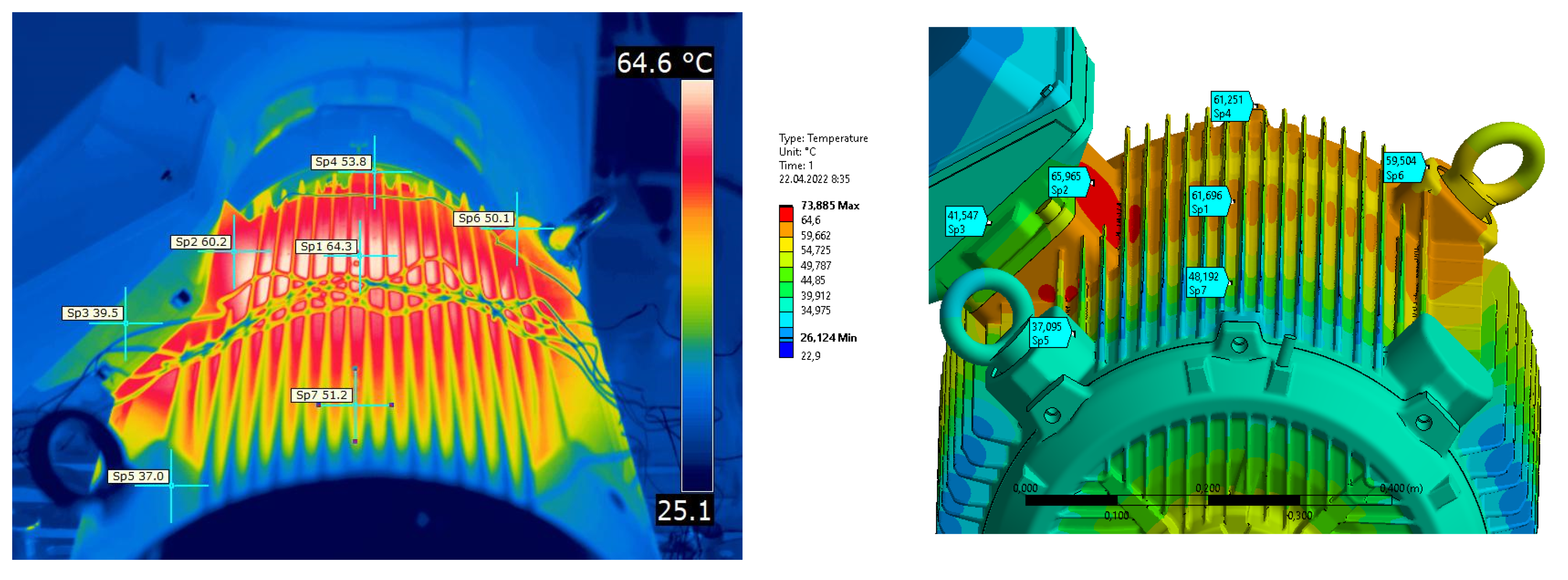
The investigation revealed that the main cause of cold areas in the middle part of the motor is the absence of circulation flow inside the induction motor. Cooler air flows from the non-drive end shield to the drive end shield between the shaft and the rotor stack. The average axial air velocity is approx. 7.5 m/s. The hot air flows back between the motor frame and the stator stack. The average axial air velocity is approx. 1.5 m/s, and its inlet temperature is in intervals 70–80 °C. Figure 21 shows the direction of the airflow by black arrows. Significant difference (approx. 10 °C) is also evident in Figure 22 and Figure 23.
Another significant difference in the results is evident for the holders (E) and the terminal box (D). The holders and terminal box show much higher temperatures than reality (approx. 20 °C). This is due to the neglecting thermal contact resistance between the motor frame and terminal box (holders).
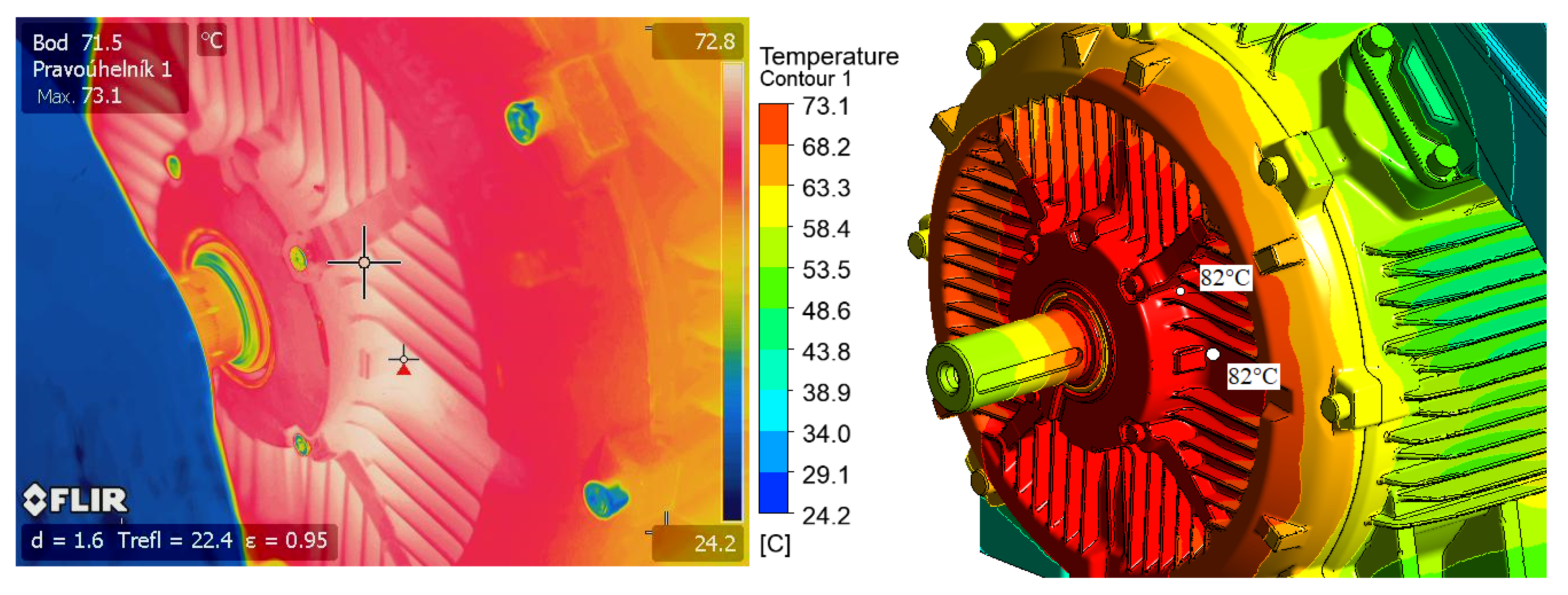
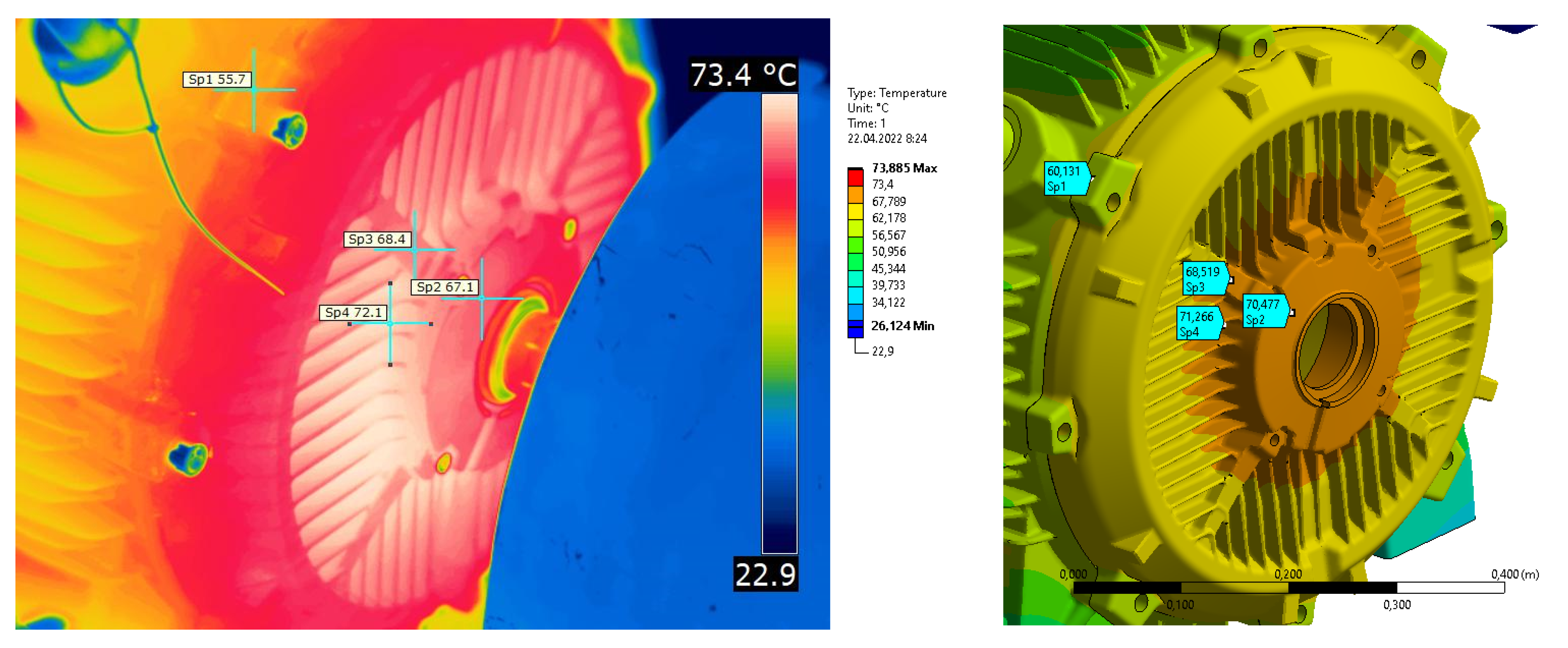
Figure 24 shows temperature distribution on the drive end-shield of the induction motor. The maximum temperature measured at the front of the shield was 73.1 °C. The CHT model showed a temperature of approximately 10 °C higher. This large inaccuracy is due to the lack of air circulation inside the motor. It is also caused by a missing clutch coupling, which partially dissipates heat from the shaft. A heat bridge is visible at the interface between the drive end shield and the motor frame.
The purpose of creating the numerical model was to determine the overall complexity of the simulation. By comparing the results between the numerical model and the measured data, the following conclusions were summarized: (1) The present study shows that it takes weeks of pure time just to prepare a simulation for a run. (2) The simulation is hardware-demanding, and it was necessary to use high-performance computing (432CPU, 1900GB RAM) to run it. (3) Each new problem discovered in the numerical model disproportionately increases time consumption. For example, the CFX preprocessing response requires a few seconds (t > 5) for each “click” mouse button. Rotating or zooming of the model is then done within minutes. (4) A numerical grid containing millions of elements is more susceptible to creating elements with negative volume; therefore, more frequent meshing is necessary.
For the reasons mentioned above, the numerical model was further tuned using only the FEM approach. The FEM approach meets the primary requirements of the project, which is to be time- and cost-efficient. All the limitations of the CHT model have been eliminated or compensated by using a new approach applied to the adequate FEM model.

7. Adequate FEM Model of Induction Motor

7.1. Convective Heat Transfer Model Application between Frame and Ambient

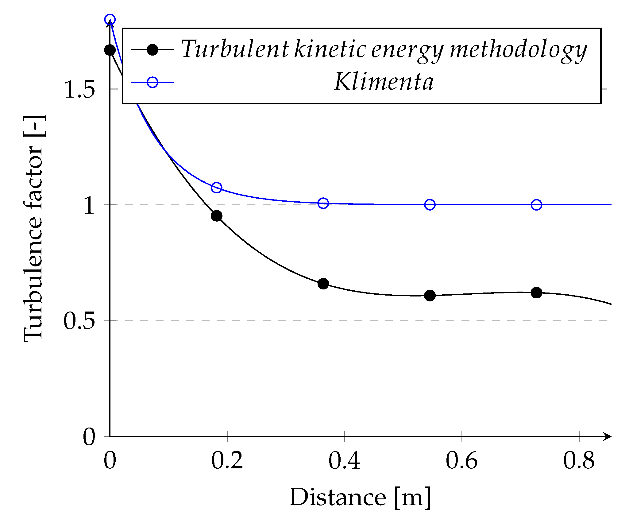
As mentioned in Section 3.1, the Heiles Equation (2) was used to calculate the HTC. In the Equation (2) there exist two unknowns depending on the distance from the fan cowl. First unknown, a velocity air profile was calculated using a CFD approach (see [7]). The second unknown, turbulence factor was calculated by the Klimenta Equation (10). Unfortunately, his Equation (10) is designed for low-power induction motors, and the temperature field of the motor frame did not correspond to reality. The average temperature was 10 °C cooler at motor frame surfaces. Figure 25 shows the difference in turbulence factors between the Klimenta relation and the turbulent kinetic energy (TKE) based methodology. It can be seen that the differences in the evaluation of the turbulent factor are significant. Since Kliment’s turbulent factor curve was significantly overestimated, the effect of turbulent kinetic energy as its equivalent replacement was investigated.
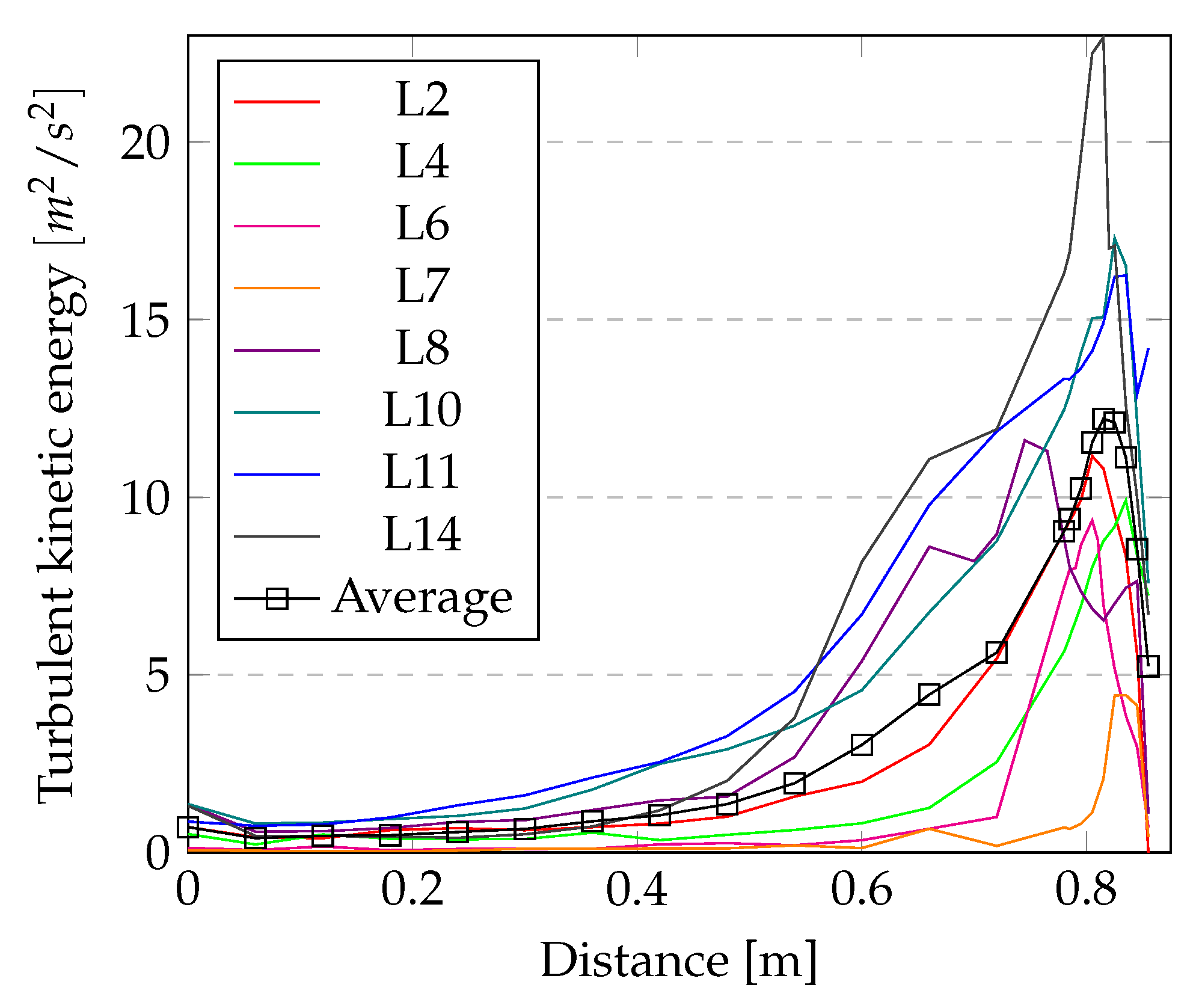
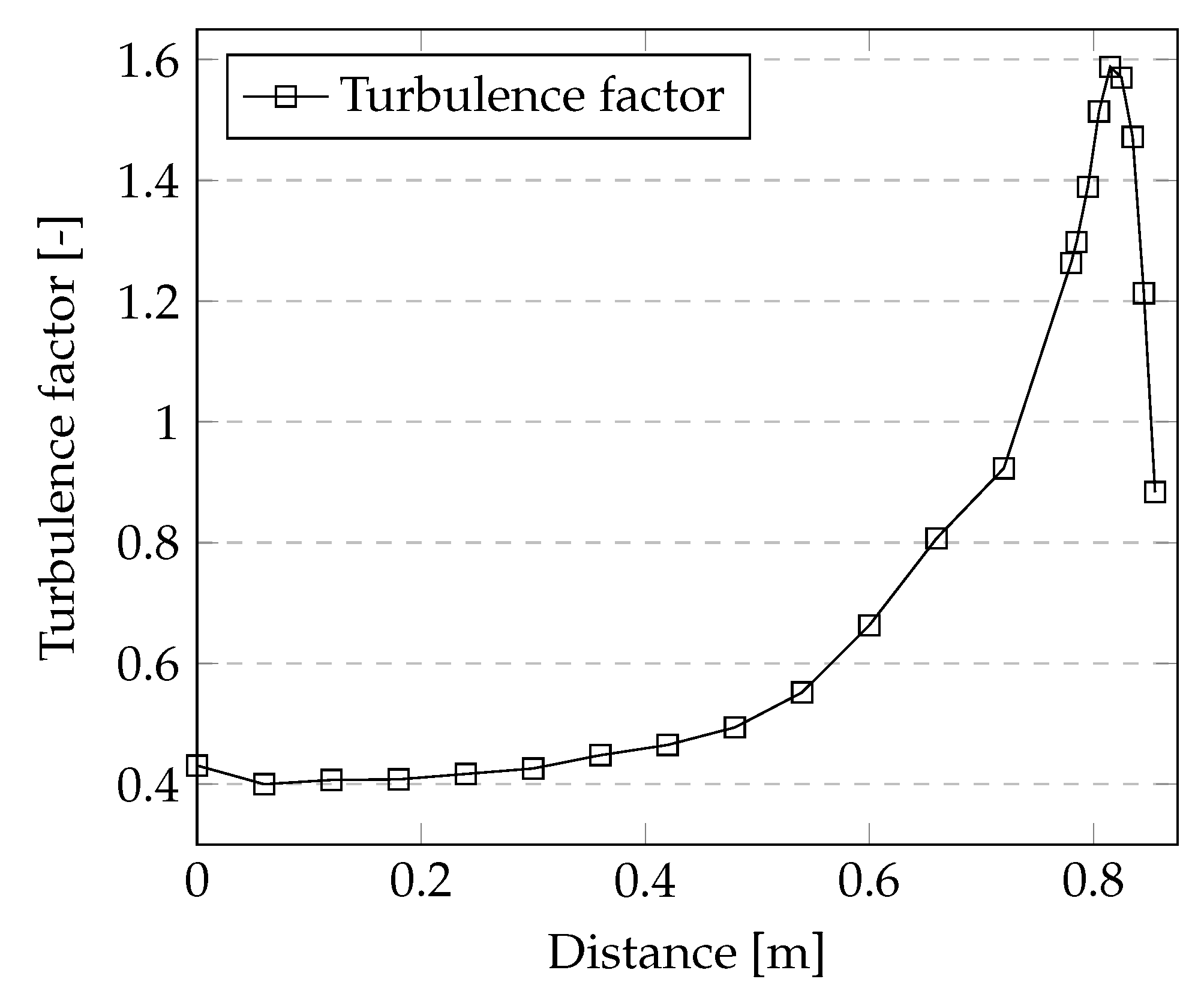
The first step was to obtain the TKE values from the CFD analysis. A total of fourteen values were obtained for the left side, thirteen for the right side, seventeen for the top side, and fourteen for the bottom side of the motor (see Figure 26). Individual TKE values were entered into tables. The tables were four, one for each side of the motor (top, bottom, left, and right). The second step produced an average of the TKE values for each side of the motor. The TKE trends are plotted only for the left side of the motor (Figure 27). For the purpose of readability, a few of the TKE curves were plotted. The average TKE value is marked by the squares. In the last step, the average TKE was converted to a turbulence factor by a simple algebraic modification, Figure 28. The trend was kept, and the maximum value of the turbulence factor was set according to Heile’s recommendation [4].
All known values were inserted into Equation (2). HTC was evaluated as a function of the y-coordinate for each side of the motor. The evaluated HTC values were stored in a *.txt file. The files were loaded using APDL commands. APDL commands (37)–(39) were inserted into the Ansys Workbench Steady Thermal model.
* d i m , H T C , t a b l e , 172 , 1 , 1 , y .
where * d i m defines an array parameter and its dimensions, H T C is the name of the parameter to be dimensioned, t a b l e is the array type (linear interpolation is done among the nearest indices and the corresponding array element values), 172 is an extent of first dimension (row), 1 is an extent of second dimension (column). Default = 1, 1 is the extent of the third dimension (plane). Default = 1. and y is the variable name corresponding to the first dimension (row).
* t r e a d , H T C , H T C , t x t , C : / A n s y s , 1 .
where t r e a d reads data from an external file into a table array parameter, H T C is a file name, t x t is a filename extension, C : / A n s y s is directory path and 1 is number of comment lines at the beginning of the file being read that will be skipped during the reading. Default = 0.
s f , H T C _ n a m e d _ s e l e c t i o n , c o n v , % H T C % , 20.2 .
where s f specifies surface loads on nodes, H T C _ n a m e d _ s e l e c t i o n nodes defining the surface upon which the load is to be applied, c o n v is a surface load label (convection), % H T C % is a tabular boundary conditions defined by (37) and 20.2 is bulk temperature.
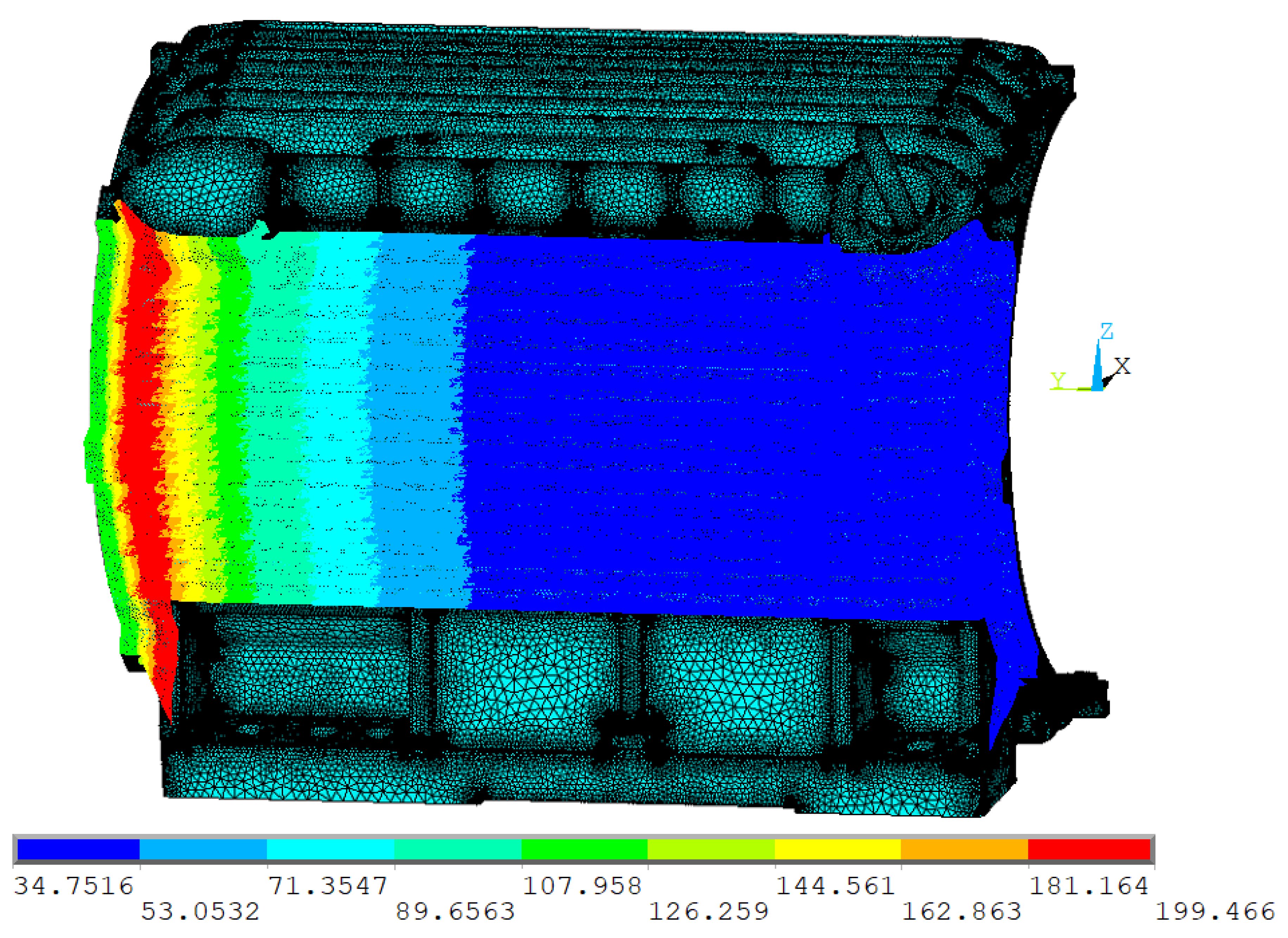
Figure 29 shows only the HTC applied on the left side of the induction motor. As you can see HTC is in the range of approx. 34 W/m 2 K to 200 W/m 2 K. HTC was defined on the other sides of the motor as well.

7.2. Heat Transfer Model Application for the End-Shield

Airflow velocity as a function of the radius was evaluated in the vicinity of the end shields. HTC was then possible to apply the relations for force convection (11) and (12) from Section 3.3. HTC is applied to the faces of the shields using the same commands (37)–(39) as for the motor frame. The only difference is in the command (37), which does not take into account a cylindrical local coordinate system (ID 101). Command (37) is then replaced by command (40).
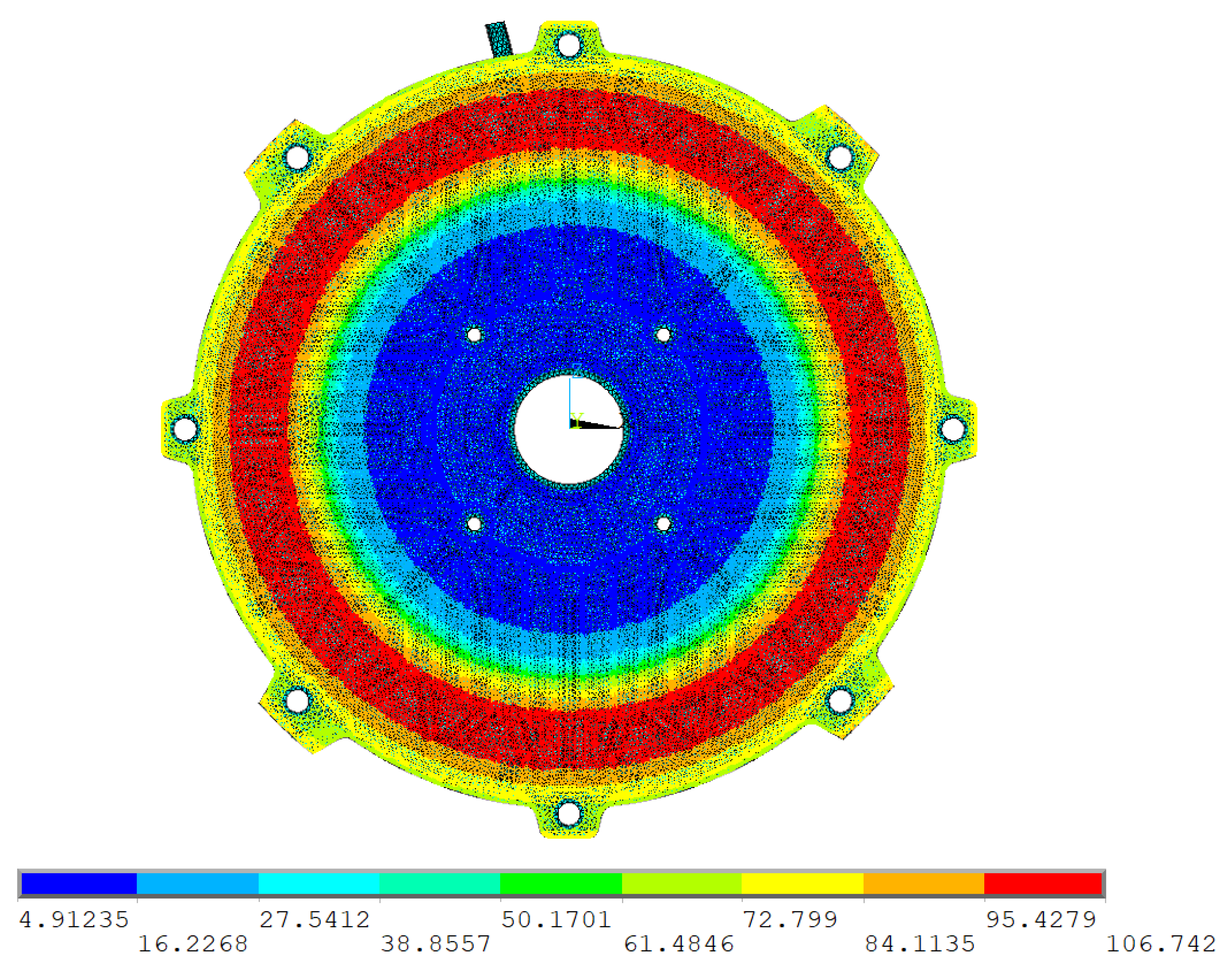
Figure 30 shows the HTC applied on the nondrive end-shield of the induction motor. As you can see, HTC is in the range of approximately 5 W/m 2 K to 110 W/m 2 K.
* d i m , H T C , t a b l e , 172 , 1 , 1 , x , , , 101 .

7.3. Turbulent Thermal Conductivity Heat Transfer Model Application for the Air Gap

The Taylor number is 414 for investigated induction motor according to (17). It means the third relation shall be applied to determine the Nusselt number from Table 1. Determining the type of Taylor number in the air gap was crucial for determining the effective thermal conductivity for the FEM model. The term effective thermal conductivity means an artificial increase of the thermal conductivity of air due to turbulent flow inside the air gap.
In Ansys CFX, the effective thermal conductivity is determined by relation (41).
λ e f f = λ m + λ T = λ m + C p · μ T P r T .
where λ m [W/mK] is the molecular thermal conductivity of the fluid, λ T [W/mK] is the turbulent thermal conductivity, which is calculated from the heat capacity at constant pressure C p [J/kgK], the turbulent viscosity μ T [Pa · s] and the Prandtl turbulent number P r T = 0.9 [ ] .
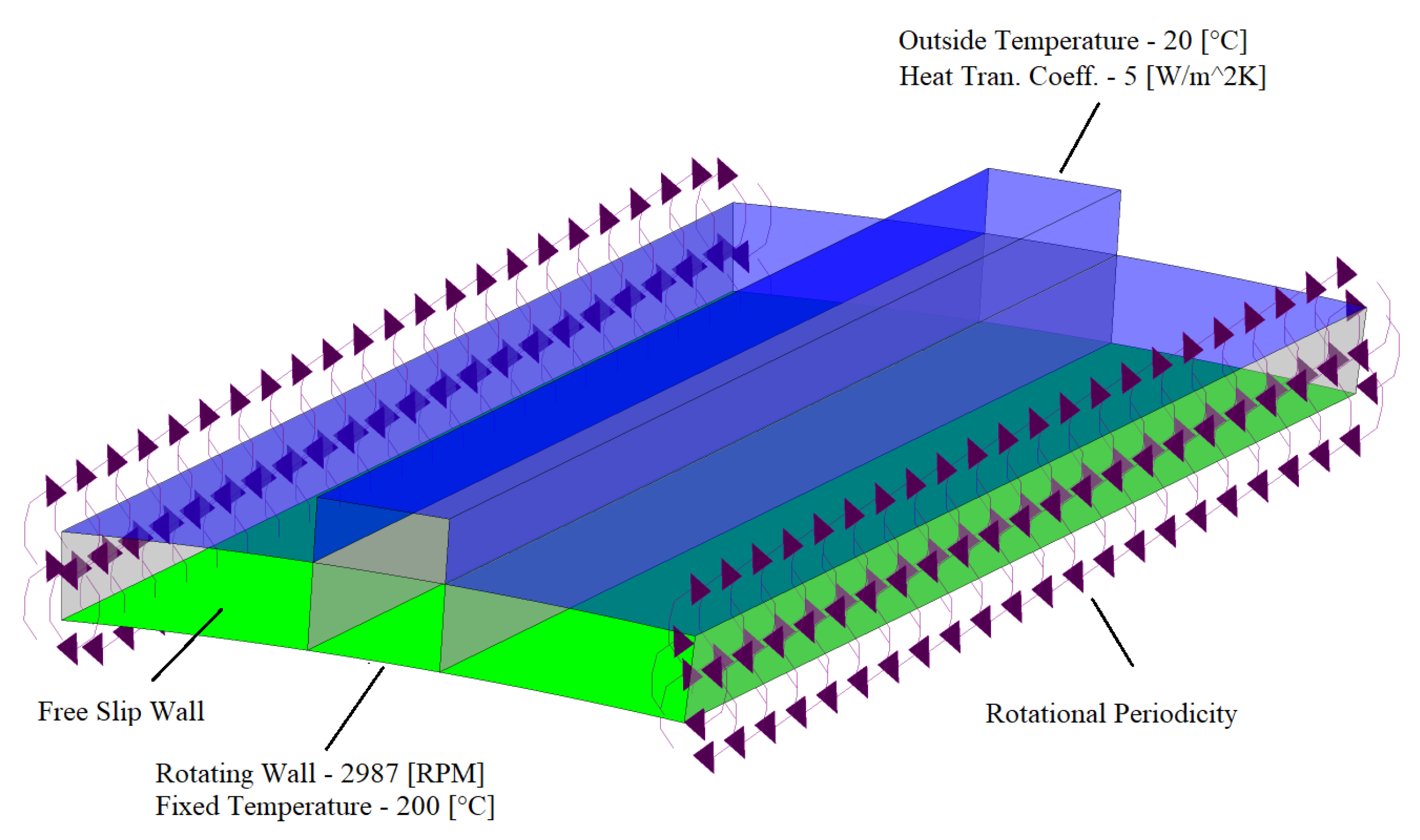
In the first step, the effective thermal conductivity was calculated on a simple air-gap domain using a CFD approach. The geometry and dimensions are of course the same as for the dimension under investigation. Figure 31 shows the simulated domain and its applied boundary conditions.
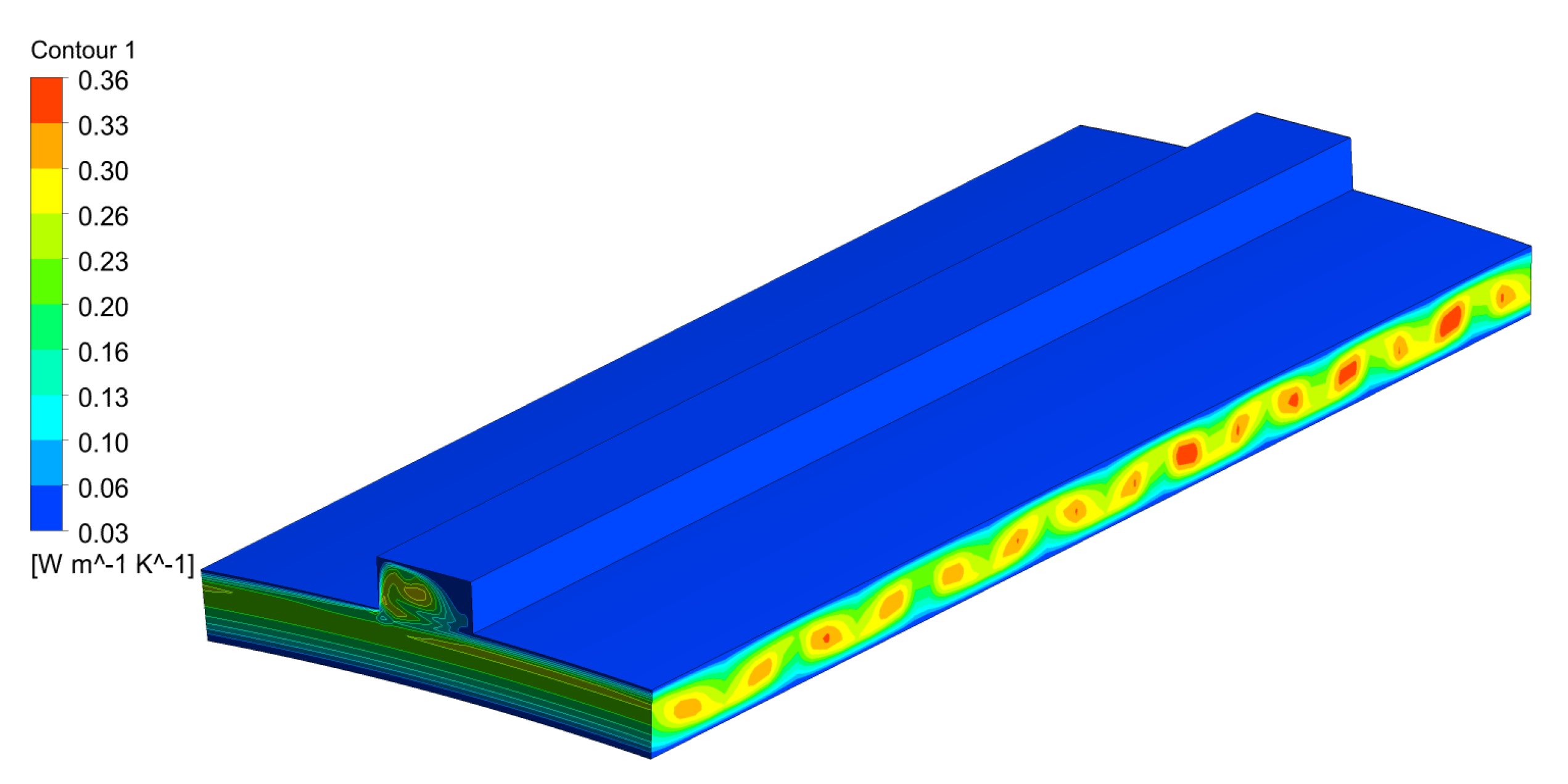
The steady-state results show that due to turbulent flow, there is an increase a heat transfer. The molecular thermal conductivity was increased from 0.0299 W/mK to 0.36 W/mK at the middle locations of the Taylor vortices, Figure 32. The average calculated value of the effective thermal conductivity was used as an initial estimate to determine the thermal conductivity for the FEM model. The adequate FEM model contained the same boundary conditions except for Free Slip walls. Free Slip walls were replaced by the plane symmetry condition.
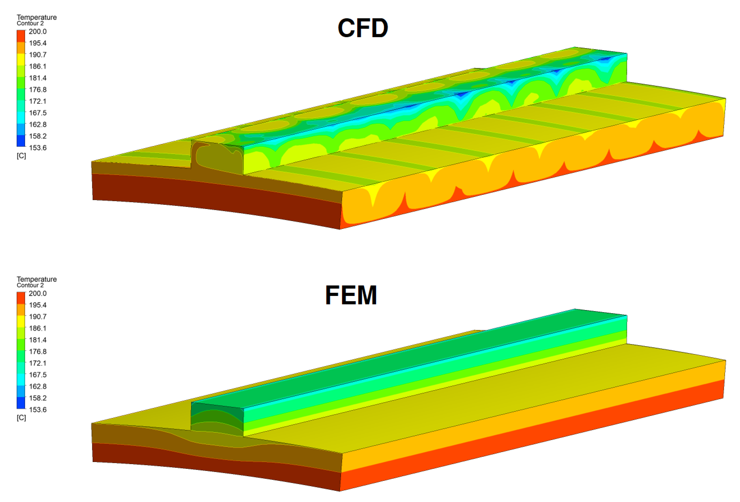
The main goal of an adequate FEM model of an air gap is to tune the thermal conductivity so that the heat transfer Q [ W ] between rotating and stationary wall is the same for both simulations (see Table 11).
The temperature difference can be seen in Figure 33. It is clear that a circular heat distribution does not appear in the FEM model because it is due to Taylor vortices. Temperature vortices could also be simulated in the FEM approach by involving an advection–diffusion equation. Unfortunately, the FEM approach in Ansys does not include an advection–diffusion equation yet.

7.4. Heat Transfer Model between End Windings and Endcap Air

A new, more accurate method of heat dissipation in the internal parts of the motor has been discovered based on experience from previous unsuccessful analyses. This method is based on the shear strain rate (SSR).
For fluids, the shear stress is a function of the shear strain rate (SSR). The property of a fluid to resist the growth of shear deformation is called viscosity. The relation between shear stress and SSR depends on fluid, and most common fluids obey Newton’s law of viscosity, which states that the shear stress is proportional to the SSR. SSR relies on CFD analyses. The SST was directly obtained from the results of the CHT analyses (see Section 6).
The idea of the new approach is based on a certain correlation between the heat transfer from the body’s surface and the magnitude of the shear strain rate. Simply described, the higher the shear strain rate, the higher the heat dissipation from the heat transfer surface can be expected.
An important assumption for the application of the new approach of heat conduction in motor air chambers is a high constant thermal conductivity of the air. Motor interiors may contain complex shield geometries, variously intertwined wire bundles, or be equipped with bearing protectors, etc. In the case of tuning artificial thermal conductivity (Section 7.3), all these modifications complicate the heat transfer mainly to inaccessible parts of the motor. It is very complicated to partition the air domain to achieve a uniform temperature distribution to all corners of the motor caused by the fast turbulent flow. A high thermal conductivity compensates for the uniform temperature distribution, namely, λ = 100 [W/mK].
However, the high thermal conductivity of the air domain in the motor creates the risk of falsely increasing the heat flux from the hot parts to the motor frame and shields. Therefore, this unwanted effect must be “throttled” in some way to achieve realistic results.
The “throttling” rate or also a newly created quantity called intensity of shear strain rate (ISSR) I S S R [m 2 /s], together with thermal contact conductivity (TCC) T C C [W/m 2 K], gave satisfactory results with the measured values. The ISSR was obtained when the SSR was divided by the area A [m 2 ], (42).
I S S R = s h e a r s t r a i n r a t e A .
All investigated contact surfaces between the air domain and the individual motor parts are shown in Figure 34. The remaining contact surfaces are defined by perfect heat transfer (TCC →).
A sensitivity analysis between I S S R and T C C was performed. It was found that the T C C = 400 [W/m 2 K] correlates to the I S S R = 625 , 747 [m 2 /s]. This linear dependence was applied to all investigated contact pairs. The previous conjugate heat transfer simulation showed that the end-winding temperature is too high. The advantage of the FEM model is that the contact approach can compensate the simplified winding geometry and/or its material model. The high end-winding temperature was reduced by increased TCC according to relation (43). A double increase of TCC will adequately reduce the end-winding temperature to the real measured value. The corrected TCC is named T C C c o r .
T C C c o r = 2 · T C C .
All the constants such as area, shear strain rate, intensity of shear strain rate, calculated thermal contact conductivity, and correct thermal contact conductivity are included in the Table 12. Reference values are marked in red.
This contact approach has been tested on other induction motors. Their nominal power was 315 kW (modified original), 48 kW, and 5.5 kW. The motors had different speeds and geometries. In all cases, the results corresponded with the measured values. The results of the FEM analysis will be explained in Section 8 with additional information.

7.5. Heat Transfer Coefficient for Remaining Surfaces and Contact Resistance

The formula from Section 3.6 determined HTC on the remaining undefined surfaces. Figure 35 shows the applied HTC values.
The slot liner forms the thermal resistance between the winding and the stator. A thin wall replaced the insulation, and its thermal contact constant can be calculated according to the relation (44). Material properties of the slot liner are given at Table 6. Other TCCs are defined according to [46]. All calculated or determined TCC values are given in Table 13. The remaining contact pairs are considered to be perfectly thermally conductive.

7.6. Compensation of Cold Places in Stator Air Pockets

The results from the thermal camera show a uniform heat distribution in the central region of the motor frame on each side, Figure 20, Figure 22 and Figure 23. However, the numerical CHT model shows a significant temperature difference. This fact has several reasons.
The first reason is the loss of direct contact between the stator stack and the motor frame. The technological process causes this during the production of the stator plates, where some pieces of the stator plates are “ bitten out”; thus, after the stator stack is assembled, air pockets between the frame and the stator are formed, Figure 10. The minimum distance between the motor frame and the stator was 2 mm, Figure 36. CHT simulation assumed that the air (nonconductor) would negligibly warm the motor frame walls. This assumption prevented enormous increases in cell number and the formation of additional fluid–solid interfaces. However, reality and later simulations have shown that the cause of the uniform warming of the motor frame walls was due to two major factors.
The first factor is the stator’s real orientation relative to the motor frame’s axial axis during pressing (see Figure 37). The original CHT model was simulated with an angle φ = 0 ; therefore the results of the cooler areas occur exactly at the locations of the air pockets. Assuming that the stator was turned by an angle of φ 45 , the air pockets would be turned to areas with more motor frame mass (feet, handles, terminal box, etc.). Therefore, there could be much less temperature reduction on the surface of the motor frame, up to the theoretical loss of information that this is occurring at all.
The flow is mainly tangential and radial in both air domains inside the motor. Still, due to the bridges (air pockets between the stator and the motor frame, air groove between the rotor and the shaft, and air gap between the stator and the rotor), there is also axial flow between the front and rear air domain. Although the velocity of the flow is not large, up to 1.5 m/s, it has a large effect on the heating of the frame walls because the warmer air flows from the drive end-shield side into the nondrive end-shield side air domain and returns through the shaft bridge (see Figure 21).
In the case of CHT simulations, air bridges have always to be modeled to make sure that axial flow occurs. This increases the computational demands on the hardware. In the case of an adequate FEM model, this situation can be compensated by a properly adjusted contact.
Figure 38 shows two cases of a contact interface. The figure on the left shows the calculation with a curved contact thermal conductivity of TCC = 14.5 W/m 2 K, which was calculated from the formula (44). Where d [m] is the minimum distance between the stator and the motor frame and λ [W/mK] is the thermal conductivity of air. The figure on the right is a simulation of perfect contact or the value T C C [W/m 2 K].
R = d λ = 0.002 0.029 = 0.068 T C C = 1 R = 14.5 W / mK .

8. Results of the FEM Approach

All results of the investigated motor are shown in Figure 39, Figure 40, Figure 41, Figure 42 and Figure 43 and summarized in Table 14, Table 15, Table 16, Table 17 and Table 18.
The bearings are critical points in terms of thermal stress on the motor. The ball bearings seats have a temperature difference of approximately 1 °C (1.5%). The temperature variations at the critical points are insignificant and within the statistical range.
The adequate FEM model approach was tested on three other different types of induction motors.
The first motor was a modified version of the 315kW motor with an optimized air gap and reduced fins. The results were similar to the motor under investigation. The maximum temperature difference (approximately 7 °C) was at point Sp4, Figure 41 or point Sp1 at Figure 42.
The second induction motor had a nominal power of 45 kW. The results were even more accurate for this type of motor than for the first two motors. The maximum temperature difference (approx. 6.5 °C) was at point Sp4 (Figure 41) or point Sp1 at Figure 42.
The last motor, with a nominal power of 5.5 kW and an aluminium frame, had the worst results. The maximum temperature difference (approximately 10 °C) was at point Sp4 (Figure 41) or point Sp1 at Figure 42. The calculated FEM temperature at the critical locations is not affected because the critical locations are sufficiently far from the location where the temperature deviation between the measured and calculated temperature was.

9. Conclusions and Discussion

The following conclusions were summarized from all the results.
The results are more than satisfactory since an adequate FEM model replaces the complex nonstationary conjugate heat transfer flow analysis. Two new methodologies for determining the heat transfer coefficient have been discovered to replace the highly demanding CFD model, for which a supercomputer is needed to make it computable in a reasonable time.
The first methodology specifies the relationship for calculating the heat transfer coefficient discovered by Mr. Heiles, for which a turbulence factor had to be determined. The turbulence factor cannot be determined by anything other than measurement, which is inappropriate and economically unacceptable for Siemens. The new methodology determines the value of the turbulence factor based on the turbulent kinetic energy obtained from the calculation of the external flow. This procedure assumes that the turbulence profile, along the length of the motor frame, is the same for both quantities. The turbulence factor was determined from the average value of the turbulent kinetic energy and its algebraic modification. The maximum magnitude of the turbulence factor was determined from the motor surface temperature results. Unfortunately, its numerical determination is not easy, and it is necessary to have at least the measured temperature on the surface of the motor frame, according to which we fit the calculated turbulent factor of the FEM model. With increasing data, from the received FEM calculations, the statistical method will already make it possible to accurately determine its magnitude without experimental data.
Due to the high turbulent flow inside the motor, heat is transferred evenly to hard-to-reach areas. The high thermal conductivity of the air domain compensated for this dynamic behavior. However, in order to avoid excessive heat dissipation from hot surfaces, the heat flow had to be “throttled” in some way. The second methodology defines this throttling. This approaches the “throttling” by using the new quantities intensity of shear strain rate (ISSR) and thermal contact conductivity (TCC). A sensitivity analysis was performed between I S S R and T C . It was found that the T C C = 400 [W/m 2 K] correlates to the I S S R = 625 , 747 [1/s m 2 ]. Thus, at the contact interfaces between the air domains and other parts inside the motor, contacts were defined with a calculated TCC that does not allow unrealistic amounts of heat to be transferred to the ambient air.
The accuracy of the heat flux setting in the air gap between the rotor and the stator is important. In this case, the heat flux calculated by CFD is compared with the heat flux calculated by the FEM model. The two values must be equal or very close. The relatively simple geometrical shape of the air gap allowed us to calculate the effective turbulent conductivity. Effective turbulent conductivity is the artificially increased molecular conductivity of the fluid, which carries the information of increased heat transfer due to turbulent flow. The effective turbulent conductivity calculated from a CFD model may differ from that of an adequate FEM model, but the equality of heat fluxes must be preserved for both approaches.
The contribution of the new calculation methodology brings huge time savings for optimising old designs and prototype development while keeping the accuracy of the results. The complex analysis using the CFD approach greatly demands computer hardware. For the calculation of this particular engine, 2200 GB of RAM, 432 CPUs, and 4 days were required, not to mention the time-consuming aspects of the overall model preparation, such as geometry preparation, boundary layer meshing, and task setup, including dozens of contact interfaces. On the other hand, an adequate FEM model offers high savings for everything. Only a workstation with a maximum of 256 GB RAM, 8 CPUs, and a maximum of 2 h of computation was needed. There was no need for a complex computational grid, which often crashed at the boundary layers. The flow simulations were solved separately on the external and internal domains without heat transfer.
In the future, Siemens will collect data to create its database from which it can statistically determine or estimate turbulence factors, flow velocity, and more. Then, an adequate FEM model is almost set up right away for the final simulation, and optimization of the old design takes days of work at most.
Author Contributions

Conceptualization, M.G.; Methodology, M.G. and T.B. (Tomáš Blejchař); Validation, M.G.; Formal analysis, M.G.; Investigation, M.G., T.B. (Tomáš Blejchař) and M.N.; Resources, M.N.; Data curation, M.N.; Writing – original draft, M.G.; Writing – review and editing, T.B. (Tomáš Blejchař); Visualization, M.G.; Supervision, T.B. (Tomáš Brzobohatý); Project administration, T.B. (Tomáš Brzobohatý); Funding acquisition, T.B. (Tomáš Brzobohatý) All authors have read and agreed to the published version of the manuscript.

Funding

This research was funded by the Ministry of Industry and Trade Czech Republic grant number CZ.01.1.02/0.0/0.0/17_176/0015651 and Ministry of Education, Youth and Sports of the Czech Republic through the e-INFRA CZ (ID:90254).

Data Availability Statement

Data sharing does not apply to this article.

Acknowledgments

This work was supported by the Ministry of Industry and Trade Czech Republic (CZ.01.1.02/0.0/0.0/17_176/0015651) and Ministry of Education, Youth and Sports of the Czech Republic through the e-INFRA CZ (ID:90254).

Conflicts of Interest

The authors declare no conflict of interest.

Abbreviations

The following abbreviations are used in this manuscript:
CFDComputational Fluid Dynamics
CFXANSYS module for CFD
CHTConjugate heat transfer
FEMFinite Element Method
FVMFinite Volume Method
GGIGeneral Grid Interface
HPCHigh-performance computing
HTCHeat Transfer Coefficient
PETPolyethylene terephthalate
RANSReynolds-averaged Navier–Stokes
TKETurbulent kinetic energy
η [m 2 /s]Kinematic viscosity
λ [W/mK]Thermal conductivity
λ a [W/mK]Equivalent thermal conductivity of the insulation amalgam
λ a i r 55 [W/mK]Thermal conductivity at 55 °C
λ a x i a l Axial thermal conductivity
λ c i [W/mK]Thermal conductivity of conductor insulation
λ c u [W/mK]Thermal conductivity of conductor
λ e [W/mK]Equivalent thermal conductivity
λ e f f [W/mK]Effective thermal conductivity
λ i i [W/mK]Thermal conductivity of impregnation insulation
λ L [W/mK]Lamination thermal conductivity
λ m [W/mK]Molecular thermal conductivity
λ r a d i a l Radial thermal conductivity
λ T [W/mK]Turbulent thermal conductivity
λ y [W/mK]Through-stack thermal conductivity
λ t h e t a Theta thermal conductivity
υ a i r [-]Volume ratio of the air.
υ c i [-]Volume ratio of conductor insulation
υ c u [-]Volume ratio of conductor
υ i i [-]Volume ratio of impregnation insulation
μ [Pa · s]Air dynamic viscosity
μ T [Pa · s]Turbulent viscosity
ρ [kg/m 3 ]Density of air
ρ e [kg/m 3 ]Equivalent density
Θ [-]Expression defined by constants
σ R M S [m]Surface roughness of contacting surfaces
Ω [rad/s]Angular velocity of rotor
ω [rad/s]Angular velocity of rotor
A [m 2 ]Area
b [m]Radius of a rotor
b 1 [m]Top width between ribs
b 2 [m]Bottom width between ribs
Cf [-]Skin friction coefficient
C 1 [-]Airflow conditions constant
C 2 [m · rpm]Constant determines the slope of the curve
C 3 [-]Constant relates on a number of poles
C p [J/kgK]Specific heat capacity
C p e [J/kgK]Equivalent specific heat capacity
C p , a i r [J/kgK]Specific heat capacity of air
C p , c i [J/kgK]Specific heat capacity of conductor insulation
C p , c u [J/kgK]Specific heat capacity of conductor
C p , i i [J/kgK]Specific heat capacity of impregnation insulation
D [m]Hydraulic diameter
d [m]Minimum distance between stator and motor frame
f [-]Turbulence factor
H [Pa]Surface micro hardness
H s h [m]Distance of the shaft centre from the base
H T C ( v , f ) [W/m 2 K]Heat transfer coefficient as a function of axial distance and turbulence factor
h 1 [m]Height of fins
I S S R [m 2 /s]Intensity of shear strain rate
K ξ , y [-]Turbulence factor as function of axial distance
K 1 [-]Coefficient representing the minimum value of the turbulence factor
K 2 [-]Coefficient representing the maximum value of the turbulence factor
K 3 [m 1 ]Coefficient describing the reduction of the turbulence factor
k 1 [-]Natural convection constant
k 2 [-]Forced convection constant
k 3 [-]Forced convection constant
L [m]Axial length of cooling fins
L 5 [m]Average fin length
L p a r [m]Wall length
l g [m]Air gap radial lenght
l i [m]Insulation thickness
m [-]Expression defined by constants
Nu [-]Nusselt number
O [m]Wetted perimeter
P [-]Power
P [Pa]Contact pressure
P F [-]Packing factor
Pr [-]Prandtl number
P r T 9 [-]Turbulent Prandtl number
p [-]Number of poles
Q [W]Heat transfer
R [mK/W]Thermal resistance
Re [-]Reynold number
R c [m 2 K/W]Interlamination thermal contact resistance
R e ψ Reynolds number for rotating wall
R e L [-]Reynold number for parallel wall
R r [m]Radius of a rotor
r [m]Radius of end-shield
r c [m]Conductor radius
S [m 2 ]Area of space between fins
S p x [°C]Monitoring point
S S R [1/s]Shear strain rate
T C C [W/m 2 K]Thermal contact conductivity
T C C c o r [W/m 2 K]Corrected thermal contact conductivity
TX [°C]Monitoring point
Ta [-]Taylor number
t [m]Thickness of steel sheet
t C 5 [m]Lamination coating thickness
V 0 [m/s]Initial velocity
v [m/s]Speed of air around end-windings
v a v e [m/s]Average air velocity
v ( y ) [m/s]Air-flow velocity
y [m]Longitudinal distance

References

  1. Touhami, S.; Bertin, Y.; Lefèvre, Y.; Llibre, J.-F.; Hénaux, C.; Fénot, M. Lumped Parameter Thermal Model of Permanent Magnet Synchronous Machines; Electrimacs: Toulouse, France, 2017. [Google Scholar]
  2. Anderson, J.D., Jr. Computational Fluid Dynamics. The Basics with Applications; McGraw-Hill: New York, NY, USA, 1995; ISBN 0-07-001685-2. [Google Scholar]
  3. Klimenta, D.O.; Hannukainen, A. An Approximate Estimation of Velocity Profiles and Turbulence Factor; Thermal Science: Belgrade, Serbia, 2017; pp. 1515–1527. [Google Scholar] [CrossRef] [Green Version]
  4. Heiles, F. Design and Arrangement of Cooling Fins, Elecktrotecknik and Maschinenbay. July 1952; Volume 69, No. 14.
  5. Wilcox, D.C. Turbulence Modeling for CFD, 3rd ed.; DCW Industries: Maharashtra, India, 2006; ISBN 978-1928729082. [Google Scholar]
  6. Staton, D.A.; Cavagnino, A. Convection Heat Transfer and Flow Calculations Suitable for Analytical Modelling of Electric Machines. In Proceedings of the IECON 2006—32nd Annual Conference on IEEE Industrial Electronics, Paris, France, 7–10 November 2006; pp. 4841–4846. [Google Scholar] [CrossRef]
  7. Gebauer, M.; Blejchař, T.; Brzobohatý, T.; Karásek, T.; Nevřela, M. Determination of Aerodynamic Losses of Electric Motors. Symmetry 2022, 14, 2399. [Google Scholar] [CrossRef]
  8. Boglietti, A.; Cavagnino, A.; Staton, D. Determination of Critical Parameters in Electrical Machine Thermal Models. IEEE Trans. Ind. Appl. 2008, 44, 1150–1159. [Google Scholar] [CrossRef]
  9. Di Gerlando, A.; Vistoli, I. Improved Thermal Modelling of Induction Motors for Design Purposes. In Proceedings of the IET 6th International Conference on Electrical Machines and Drives, Oxford, UK, 8–10 September 1993; pp. 381–386. [Google Scholar]
  10. Valenzuela, M.A.; Tapia, J.A. Heat Transfer and Thermal Design of Finned Frames for TEFC Variable Speed Motors. In Proceedings of the 32nd Annual Conference on IEEE Industrial Electronics—IECON 2006, Paris, France, 7–10 November 2006; pp. 4835–4840. [Google Scholar]
  11. Valenzuela, M.A.; Tapia, J.A. Heat Transfer and Thermal Design of Finned Frames for TEFC Variable-Speed Motors. IEEE Trans. Ind. Electron. 2008, 55, 3500–3580. [Google Scholar] [CrossRef]
  12. Grabowski, M.; Urbaniec, K.; Wernik, J.; Wołosz, K.J. Numerical simulation and experimental verification of heat transfer from a finned housing of an electric motor. Energy Convers. Manag. 2016, 125, 91–96. [Google Scholar] [CrossRef]
  13. Ajay, C.; Nihaarikha, G.N.; Hirajith, D.S.; Vishnuprada, A.R.; Sreekanth, M.; Feroskhan, M. Numerical analysis of heat transfer in electric motor casing made of ceramic reinforced aluminium matrix composites. Mater. Today Proc. 2022, 51, 1510–1515. [Google Scholar] [CrossRef]
  14. Xie, Y.; Wang, Y. 3D temperature field analysis of the induction motors with broken bar fault. Appl. Therm. Eng. 2014, 66, 25–34. [Google Scholar] [CrossRef]
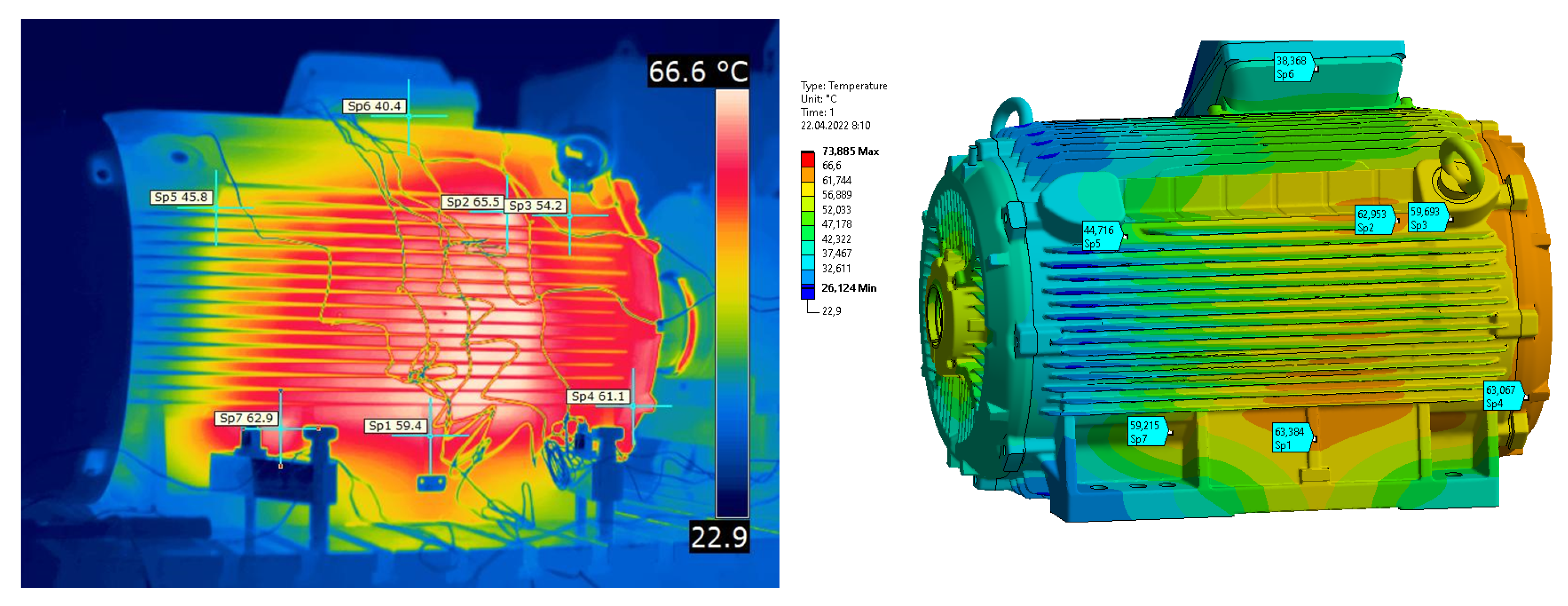
  15. Appadurai, M.; Raj, E.F.I.; Venkadeshwaran, K. Finite element design and thermal analysis of an induction motor used for a hydraulic pumping system. Mater. Today Proc. 2021, 45, 7100–7106. [Google Scholar] [CrossRef]
  16. Bousbaine, A. An Investigation into the Thermal Modelling of Induction Motors; Department of Electronic and Electrical EngineeringG, University of Sheffield: Sheffield, UK, 1993. [Google Scholar]
  17. Chapman, A.J. Heat Transfer, 2nd ed.; MaCmillan Co.: New York, NY, USA, 1967. [Google Scholar]
  18. Taylor, G.I. Distribution of velocity and temperature between concentric cylinders. Proc. R. Soc. 1935, 159, 546–578. [Google Scholar]
  19. Anderson, K.R.; Lin, J.; Wong, A. Experimental and Numerical Study of Windage Losses in the Narrow Gap Region of a High-Speed Electric Motor. Fluids 2018, 3, 22. [Google Scholar] [CrossRef] [Green Version]
  20. Staton, D.A.; Boglietti, A.; Cavagnino, A. Solving the More Difficult Aspects of Electric Motor Thermal Analysis; IEMDC: Madison, WI, USA, 2003. [Google Scholar]
  21. Boglietti, A.; Cavagnino, A. Analysis of the End winding Cooling Effects in TEFC Induction Motors. IEEE Trans. Ind. Appl. 2007, 43, 1214–1222. [Google Scholar] [CrossRef] [Green Version]
  22. Boglietti, A.; Cavagnino, A.; Lazzari, M.; Pastorlli, M. A simplified thermal model for variable speed self-cooled induction motor. IEEE Trans. Ind. Appl. 2003, 39, 945–952. [Google Scholar] [CrossRef]
  23. Mellor, P.H.; Roberts, D.; Turner, D.R. Lumped parameter thermal model for electrical machines of TEFC design. IEE Proc. B 1991, 138, 205–218. [Google Scholar] [CrossRef]
  24. Staton, D.A.; Popescu, M.; Hawkins, D.; Boglietti, A.; Cavagnino, A. Influence of different end region cooling arrangements on end-winding heat transfer coefficients in electrical machines. In Proceedings of the 2010 IEEE Energy Conversion Congress and Exposition, Atlanta, GA, USA, 12–16 September 2010; pp. 1298–1305. [Google Scholar] [CrossRef]
  25. Duran, M.J.; Fernandez, J. Lumped-parameter thermal model for induction machines. IEEE Trans. Energy Convers. 2004, 19, 791–792. [Google Scholar] [CrossRef]
  26. Romo, J.L.; Adrian, M.B. Prediction of Internal Temperature in Three-Phase Induction Motors with Electronic Speed Control. Electr. Power Syst. Res. 1998, 45, 91–99. [Google Scholar] [CrossRef]
  27. Incropera, F.; Bergman, T.; Lavine, A. Foundations of Heat Transfer; Wiley: Hoboken, NJ, USA, 2013; pp. 402–404. ISBN 9780470646168. [Google Scholar]
  28. Geankoplis, C.J. Transport Processes and Separation Process Principles, 4th ed.; Pearson: London, UK, 2003; p. 475. [Google Scholar]
  29. Gebauer, M.; Brzobohatý, T.; Blejchař, T.; Karásek, T. Numerical simulation of heat treatment process of aluminium profiles. J. Mech. Eng. 2019, 69, 43–50. [Google Scholar] [CrossRef] [Green Version]
  30. Childs, P. Rotating Flow. Contemp. Phys. 2012, 53, 534. [Google Scholar] [CrossRef]
  31. Elghnam, R.I. Experimental and numerical investigation of heat transfer from a heated horizontal cylinder rotating in still air around its axis. Ain Shams Eng. J. 2014, 5, 177–185. [Google Scholar] [CrossRef] [Green Version]
  32. Bennion, K. Electric Motor Thermal Management; National Renewable Energy Laboratory: Golden, CO, USA, 2017. [Google Scholar]
  33. Hashin, Z.; Shtrikman, S. A variational approach to the theory of the effective magnetic permeability of multiphase materials. J. Appl. Phys. 1962, 33, 3125–3131. [Google Scholar] [CrossRef]
  34. Hashin, Z. Theory of Fiber Reinforced Materials; NASA Contractor Rep.; NASA: Washington, DC, USA, 1972. [Google Scholar]
  35. Simpson, N.; Wrobel, R.; Mellor, P.H. Estimation of Equivalent Thermal Parameters of Impregnated Electrical Windings. IEEE Trans. Ind. Appl. 2013, 49, 2505–2515. [Google Scholar] [CrossRef]
  36. Progelhof, R.C.; Throne, J.L.; Ruetsch, R.R. Methods for predicting the thermal conductivity of composite systems A review. Polym. Eng. Sci. 1976, 16, 615–625. [Google Scholar] [CrossRef]
  37. Behrens, E. Thermal conductivities of composite materials. J. Compos. Mater. 1968, 2, 2–17. [Google Scholar] [CrossRef]
  38. Donea, J. Thermal conductivities based on variational principles. J. Compos. Mater. 1972, 6, 262–266. [Google Scholar] [CrossRef]
  39. Hamilton, R.; Crosser, O. Thermal conductivity of heterogeneous two component systems. Ind. Eng. Chem. Fundam. 1962, 1, 187–191. [Google Scholar] [CrossRef]
  40. Idoughi, L.; Mininger, X.; Bouillault, F.; Bernard, L.; Hoang, E. Thermal Model with winding Homogenization and FIT Discretization for Stator Slot. IEEE Trans. Magn. 2011, 47, 4822–4826. [Google Scholar] [CrossRef]
  41. Siesing, L.; Reinap, A.; Andersson, M. Thermal properties on high fill factor electrical windings: Infiltrated vs. non infiltrated. In Proceedings of the 2014 International Conference on Electrical Machines (ICEM), Berlin, Germany, 2–5 September 2014; pp. 2218–2223. [Google Scholar]
  42. Pecinka, P.; Kocman, S.; Orsag, P.; Otýpka, J. Solutions to increase the efficiency of induction motors. In Proceedings of the 18th International Scientific Conference on Electric Power Engineering, Ostrava, Czech Republic, 17–19 May 2017. [Google Scholar] [CrossRef]
  43. Lee, J.-J.; Kim, Y.-K.; Nam, H.; Ha, K.-H.; Hong, J.-P.; Hwang, D.-H. Loss distribution of three-phase induction motor fed by pulsewidth-modulated inverter. IEEE Trans. Magn. 2004, 40, 762–765. [Google Scholar] [CrossRef]
  44. Rehman, Z.; Seong, K. Three-D Numerical Thermal Analysis of Electric Motor with Cooling Jacket. Energies 2018, 11, 92. [Google Scholar] [CrossRef] [Green Version]
  45. Ferziger, J.H.; Peric, M. Computational Methods for Fluid Dynamics; Springer: Berlin/Heidelberg, Germany, 1996; ISBN 3-540-59434-5. [Google Scholar]
  46. Karthik, N.B. Thermal Contact Resistance:Experiments and Simulation; Department of Applied Mechanics, Chalmers Univestity of Tenchology: Gothenburg, Sweden, 2015. [Google Scholar]
Figure 1. 3D model of the electric motor: (a) Front view. (b) Rear view.
Symmetry 15 01294 g001
Figure 2. A view into the motor under investigation.
Symmetry 15 01294 g002
Figure 3. Air-flow velocity profile.
Symmetry 15 01294 g003
Figure 4. Dimensions of fin.
Symmetry 15 01294 g004
Figure 5. Comparison turbulence factor with measurement.
Symmetry 15 01294 g005
Figure 6. Correlation coefficients of the convective cooling around end-winding.
Symmetry 15 01294 g006
Figure 7. Lamination stack of the stator and rotor.
Symmetry 15 01294 g007
Figure 8. Arrangement in the stator groove.
Symmetry 15 01294 g008
Figure 9. Arrangement in the stator slot.
Symmetry 15 01294 g009
Figure 10. Distributions of total iron losses.
Symmetry 15 01294 g010
Figure 11. Distributions of corrected stator winding losses.
Symmetry 15 01294 g011
Figure 12. Distributions of corrected rotor winding losses.
Symmetry 15 01294 g012
Figure 13. A general view of the fluid final computational grid.
Symmetry 15 01294 g013
Figure 14. Motor enclosing domains.
Symmetry 15 01294 g014
Figure 15. Internal domains of electric motor.
Symmetry 15 01294 g015
Figure 16. A general view of the solid final computational grid.
Symmetry 15 01294 g016
Figure 17. Position of a monitoring point.
Symmetry 15 01294 g017
Figure 18. Temperature distribution on the surfaces of the induction motor.
Symmetry 15 01294 g018
Figure 19. Temperature distribution inside the induction motor.
Symmetry 15 01294 g019
Figure 20. Temperature distribution on the left side of the induction motor.
Symmetry 15 01294 g020
Figure 21. Circulation flow between motor frame - stator stack and shaft - rotor stack.
Symmetry 15 01294 g021
Figure 22. Temperature distribution on the right side of the induction motor.
Symmetry 15 01294 g022
Figure 23. Temperature distribution on the top side of the induction motor.
Symmetry 15 01294 g023
Figure 24. Temperature distribution on the drive end-shield of the induction motor.
Symmetry 15 01294 g024
Figure 25. Turbulence factors.
Symmetry 15 01294 g025
Figure 26. Identification of positions of the individual areas between the fins.
Symmetry 15 01294 g026
Figure 27. Turbulent kinetic energy on the left side of the induction motor.
Symmetry 15 01294 g027
Figure 28. Turbulence factor derived from turbulent kinetic energy.
Symmetry 15 01294 g028
Figure 29. Heat transfer coefficient for the left side of the motor.
Symmetry 15 01294 g029
Figure 30. Heat transfer coefficient for nondrive end-shield of the motor.
Symmetry 15 01294 g030
Figure 31. CFD model including boundary conditions.
Symmetry 15 01294 g031
Figure 32. Effective thermal conductivity.
Symmetry 15 01294 g032
Figure 33. Result comparison of the CFD and the adequate FEM model.
Symmetry 15 01294 g033
Figure 34. Investigated thermal contact surfaces.
Symmetry 15 01294 g034
Figure 35. Heat transfer coefficient for remaining surfaces.
Symmetry 15 01294 g035
Figure 36. Air gap between stator and motor frame.
Symmetry 15 01294 g036
Figure 37. Air gap between stator and motor frame.
Symmetry 15 01294 g037
Figure 38. Air gap between stator and motor frame.
Symmetry 15 01294 g038
Figure 39. Comparison of the results at the left side of the investigated motor.
Symmetry 15 01294 g039
Figure 40. Comparison of the results on right side of the investigated motor.
Symmetry 15 01294 g040
Figure 41. Comparison of the results at the top side of the investigated motor.
Symmetry 15 01294 g041
Figure 42. Comparison of the results at front side of the investigated motor.
Symmetry 15 01294 g042
Figure 43. Comparison of the results at monitoring point of the investigated motor.
Symmetry 15 01294 g043
Table 1. Calculation of Nusselt number.
Nusselt Number NUCondition of Taylor Number
2 T a < 41
0.202 · T a 0.63 · P r 0.27 41 < T a < 100
0.386 · T a 0.5 · P r 0.27 T a > 100
Table 2. Correlation coefficients of the convective cooling around end-winding.
Correlation k 1 [ ] k 2 [ ] k 3 [ ]
[21]41.40.151
[22]15.50.291
[23]15.50.391
[24]150.40.9
Table 3. Motor lamination constants.
ConstantValueUnits
t0.3[mm]
λ L 36[W/mK]
σ R M S 1[ μ m]
P0.4[MPa]
H1200[MPa]
t C 5 2[ μ m]
λ a i r 55 0.0281[W/mK]
λ a x i a l λ y 1.52[W/mK]
λ r a d i a l λ x 36[W/mK]
λ t h e t a λ z 36[W/mK]
Table 4. Material properties of electrical winding.
Material λ [W/mK] C p [J/kgK] ρ [kg/m 3 ]
Conductor396392.61200
Impregnation0.2314258960
Isolation0.810001440
Table 5. The equivalent material properties of winding.
λ [W/mK] λ axial [W/mK] C p [J/kgK] ρ [kg/m 3 ]
0.61179.59674730
Table 6. Material properties.
Part Name λ [W/mK] C p [J/kgK] ρ [kg/m 3 ]
Motor frame, end-shields, bearing cover515407150
Terminal box515407150
Rotor, Stator1.52, 36, 364417850
Winding0.61, 179.59574715
Rotor cage1959012700
Shaft, bolts, bearings534707850
Fan cowl, plugs0.4113001350
Inner cover0.2413002000
Terminal panel0.310001400
Floor310002300
Sealing rings0.2513501300
Slot liners0.1751355818
Table 7. Preprocessing settings.
Analysis TypeSteady State
InterfacesFrozen Rotor
RoughnessNeglected
WallsNo Slip Wall
Turbulence Intensity5%
Reference Pressure1 atm.
BuoyantNo
Turbulent Modelk- ω SST
Thermal ModelThermal Energy
Thermal InitializationAutomatic
Rotational Speed2987 [rpm]
Table 8. Solver settings.
Analysis TypeSteady State
Turbulence NumericHigh Resolution
Max.Iterations50,000
Fluid TimescaleAutomatic
Solid TimescaleAutomatic
Advection SchemeHigh Resolution
Convergence CriteriaRMS
Conservaion Target0.01
Residual Target 1 × 10 6
Table 9. Comparison of CFD results and measurements.
Monitoring PoitsMeasurement [°C]CFD [°C]Difference [°C]
T 1 E n d w i n d i n g D 115.2132+16.8
T 2 E n d w i n d i n g N D 95.2125.8+30.6
T 3 B e a r i n g D 79.879.2−0.6
T 4 B e a r i n g N D 51.847.9−3.9
T 5 M o t o r f r a m e 63.959.1−4.8
T 9 R o t o r 114.8113−1.8
Table 10. Specification of the Flir 620.
MeasurementRange
Temperature ranges−40 °C to +500 °C, in 2 ranges; up to +2000 °C
Accuracy (% of reading) ± 2 °C or ± 2 % of reading
Thermal sensitivity @ 50/60 Hz65 mK at 30 °C (86 °F)
Emissivity correctionvariable from 0.1 to 1.0 or select from listings in the predefined material list
Table 11. Comparison of CFD and FEM results.
Simulation λ [W/mK]Q [W]
CFD0.1971.067
FEM0.251.06
Table 12. Calculated thermal contact conductivity.
ContactArea [m 2 ]SSR [1/s]ISSR [m 2 /s]TCC [W/m 2 K] TCC cor [W/m 2 K]
1. Fluid − Stator0.11232597553,19634-
2. Fluid − Cage0.1723226,770155,35099.3-
3. FLuid − Shaft0.0767712,300160,218102.4-
4. Fluid − Wires0.3163973830,78719.639.2
5. Fluid − EW Front0.0593537,140625,747400800
6. Fluid − EW Outer0.1482704247,6513060
7. Fluid − EW Inner0.1046350,000477,874305610
8. Fluid − EW Rear0.050999208181,743116232
Table 13. Thermal contact conductivity.
ContactTCC [W/m 2 K]
1. Motor  frame—Shields1000
2. Motor  frame—Screws  (M16)1000
3. Motor  frame—Terminal  box  (adapter)250
4. Termina l box  (middle side)—Terminal  box  (entry plate)1000
5. Terminal  box  (middle side)—Terminal  box  (cover)1000
6. Termina l box  (middle side)—Terminal  box  (adapter)1000
7. Shaft—Shaft  seal100
8. Slot  liner—Winding486
Table 14. Comparison of the results at the left side of the investigated motor.
Sp1Sp2Sp3Sp4Sp5Sp6Sp7
Measurement [°C]59.465.554.261.145.840.462.9
FEM [°C]63.462.959.76344.738.459.2
Difference [°C]+4−3.6+5.5+2.9−1.1−2−3.7
Table 15. Comparison of the results at the right side of the investigated motor.
Sp1Sp2Sp3Sp4Sp5Sp6Sp7
Measurement [°C]67.85961.341.339.959.353.1
FEM [°C]62.563.56043.537.661.147.2
Difference [°C]−5.3+4.5−1.3+2.2−2.3+1.8−5.9
Table 16. Comparison of the results at the top side of the investigated motor.
Sp1Sp2Sp3Sp4Sp5Sp6Sp7
Measurement [°C]64.360.239.553.83750.151.2
FEM [°C]61.765.941.561.337.159.548.2
Difference [°C]−2.6+5.7+2+7.5+0.1−9.4−3
Table 17. Comparison of the results at the front side of the investigated motor.
Sp1Sp2Sp3Sp4
Measurement [°C]55.767.168.472.1
FEM [°C]60.170.568.571.3
Difference [°C]+4.6+3.4+0.1−0.8
Table 18. Comparison of the results at monitoring point of the investigated motor.
M 2017M 2021FEMDifference
T1 [°C]112.5115.8121.59 (6)
T2 [°C]93.610098.95.3 (1.1)
T3 [°C]76.77071.55.2 (1.5)
T4 [°C]51.854.7520.2 (2.7)
T5 [°C]56.660.164.57.9 (4.4)
T6 [°C]-80.580.8−(0.3)
T7 [°C]-70.461.2−(9.2)
T9 [°C]110.5114109.51 (4.5)
Disclaimer/Publisher’s Note: The statements, opinions and data contained in all publications are solely those of the individual author(s) and contributor(s) and not of MDPI and/or the editor(s). MDPI and/or the editor(s) disclaim responsibility for any injury to people or property resulting from any ideas, methods, instructions or products referred to in the content.