Article

Kinetic Interaction between an Electron Flow with a Wide Velocity Spread and a Short-Adjusted Slipping Wave Pulse at the Cherenkov Resonance

1
Department of Plasma Physics and High-Power Electronics, Institute of Applied Physics, Russian Academy of Sciences, 46 Ulyanov St., 603950 Nizhny Novgorod, Russia
2
Faculty of Business Informatics and Applied Mathematics, National Research University Higher School of Economics (HSE University), 25/12 Bolshaya Pecherskaya Street, 603155 Nizhny Novgorod, Russia
3
Advanced School of General and Applied Physics, National Research University “N. I. Lobachevsky State University of Nizhny Novgorod”, 603950 Nizhny Novgorod, Russia
*
Author to whom correspondence should be addressed.
Symmetry 2023, 15(4), 838; https://doi.org/10.3390/sym15040838
Submission received: 19 January 2023 / Revised: 28 March 2023 / Accepted: 29 March 2023 / Published: 31 March 2023
(This article belongs to the Special Issue Advances in Synchrotron and Undulator Radiation Studies Ⅱ)

Abstract

:
In this study, kinetic interaction at the Cherenkov resonance between an electromagnetic wave pulse and a flow of electrons possessing a wide velocity spread at the scale of the characteristic range of the resonant electron wave interaction is considered. Due to the absence of a distribution function slope in the range of velocities corresponding to the electron wave’s resonance, an electron’s flow is a nearly stable media from the point of view of its interaction with a long enough wave pulse. In this paper, we explain our findings on the process of electron interaction with potential relief where the wave pulse is so short that the characteristic scale of the wave amplitude’s inhomogeneity and the profile of the potential relief is comparable to the wavelength. We show that if an appropriate slippage between the phase and group velocities of the wave is provided, then the reflection process of particles from “fast” and “slow” close-to-resonance velocity fractions becomes non-symmetrical. This can provide a mechanism of amplification of short intensive wave pulses with electron flows with very large velocity spreads.

1. Introduction

Frequent and powerful quasi-monochromatic electromagnetic wave pulses were observed in various space plasma systems. For example, extensive experimental data were obtained in the course of space experiments during the projects CLUSTER and THEMIS and with the Van Allen Probes. The excitation of powerful and rapidly varying chorus emissions occurs in the Earth’s magnetosphere with marginally stable plasma [1]. Mysterious pulse radio emissions are typical for brown dwarfs and pulsars. Completely polarized radiation at GHz frequencies in the form of periodic bursts of extremely bright circularly polarized coherent radio emission were observed from brown dwarfs [2,3]. Giant pulses with sporadic occurrences represent a special form of radio emission that is considered to be typical in the GHz frequency bands observed from the Crab pulsar [4,5].
Currently, several possibilities for the coherent excitation of electromagnetic radiation are being considered in space plasma (see, e.g., [6,7]). All of these mechanisms assume the presence of a “population inversion” due to the suitable slope of a distribution function. This can take place at the leading edge of particle flows, and it can also be associated with both a loss cone in the velocity space and longitudinal currents. At present, there are no data on the distribution function of particles in the regions of excitation of the mentioned emissions from astrophysical objects. Moreover, the mechanisms behind the regular formation of strongly anisotropic distributions of particles in the momentum space within the framework of traditional mechanisms are also unknown. Thus, despite several advantages of the theory, there is no widely accepted explanation for many types of important natural pulse emission such as chorus emissions in the magnetospheres of Earth and Jupiter and the pulsed radio emissions of brown dwarfs and pulsars, which are based on the approach of a slope of a velocity distribution function of electrons in space flows.
There are traditional theoretical approaches [6,7] explaining the excitation and amplification of long wave pulses by electron flows in the presence of a slope of the charged particle distribution function at a velocity corresponding to the Cherenkov-type electron wave resonance. If the slope of the distribution function is absent, then in traditional models (describing various problems of plasma physics and the physics of electron masers), in which the effective length of the interaction of an electron with a wave is unlimited (as in, for example, problems for finding the instability growth rate in a linear approximation), such a flow of charged particles is usually considered to be an inert media. This is because in the electron flow, the number of “fast” electrons (whose velocity is slightly greater than the resonant velocity, and thus, they should pass their energy to the wave in the process of electron wave interaction) and “slow” electrons (which should absorb the wave energy) placed in the band of velocities close to the electron wave resonance is the same.
In contrast, the symmetry between the energy exchanges of “slow” and “fast” resonant electrons can be broken, even if their number is the same. It can happen when electrons interact with a short-wave pulse slipping with respect to the resonant electrons. As a result, an electron flow with a wide velocity spread can become active (either as radiation or as absorbing media). For instance, the symmetry between the energy exchanges of “slow” and “fast” electrons can be disturbed due to difference in the “lifetimes” of these electrons in the field of the wave pulse [8]. This situation takes place when the wave pulse is short enough and when its group velocity is close to the phase velocity (this is equal to the electron velocity corresponding to the exact Cherenkov electron wave resonance). In this situation, different slippages of “fast” and “slow” close-to-resonance electrons with reference to the wave pulse (and, therefore, different “lifetimes” of these electrons in the wave pulse area) lead to the transformation of an inert electronic medium into an active one (depending on the slippage sign, either absorbing or amplifying the wave pulse). This effect can result in the formation of short waves pulsed at the small-signal stage of the interactions of electron flows with initial small chaotic wave noises. Therefore, this process can be considered an analysis of the initial stage of excitation of extremely short pulses.
However, the existence of extremely short and powerful pulses in space plasma systems requires considerations of other amplification mechanisms of such pulses by electron flows with large velocity spreads. In [9], a beam pulse amplifier mechanism was proposed that explains some experimental data known for space and laboratory plasmas. The physical background of this mechanism with quasi-hydrodynamic time scale was discussed in [10,11,12]. The conditions for the applicability of this mechanism assume that the amplified pulse is so short that the inequality l w / l < Γ / ω is satisfied, where l w is the wave pulse length, l is the electron wave interaction region length, Γ is the growth rate, and ω is the frequency. Such impulses are already evolving as non-quasi-monochromatic.
In this paper, we describe a different mechanism of the kinetic interaction of an electron flow with large velocity spread and a short-adjusted wave pulse at the Cherenkov resonance. Unlike the effect described in work [8], it is not related to the difference in the “lifetimes” of different particles in the wave pulse field but to a possible asymmetry between “slow” and “fast” resonant electrons when they pass a short wave pulse and perform non-linear oscillations in the potential relief formed by a slipping resonant wave.
More specifically, in this paper, we consider a short quasi-monochromatic wave pulse whose pulse length corresponds to several wave cycles. Therefore, the potential relief describing the interaction of the close-to-resonance electrons with the wave filed is noticeably inhomogeneous. If we describe the motion of electrons on the phase plane in the adiabatic approximation (that is, when the characteristic time of the wave amplitude change is quite small on the scale of the period of electron oscillations in the wave field) in exact group synchronism (when the phase velocity is equal to the group wave velocity), then the non-homogeneity of the potential relief should lead to “reflections” of close-to-resonance electrons from this potential relief, and this process would be symmetrical for the “fast” and “slow” velocity fractions of the electron flow. However, if we take into account a small slippage between the phase and group velocities, then the symmetry is broken, and the average (over all velocity fractions) change in electron energy (in other words, the efficiency of the electron wave interaction) becomes non-zero.
In this paper, we report our study of the motion of electrons with various initial velocities in the field of a short wave pulse. We considered the case in which electrons are close to the Cherenkov resonance with the wave, and in which the group velocity of the wave pulse is close to the phase velocity. Note that such a situation can be realized in various systems [8], including in space plasma. In particular, the proximity of the phase and group velocities can be ensured for the so-called whistler waves [13,14,15] in a relatively dense plasma medium immersed in a moderate magnetic field. On the other hand, such a situation can also be realized in electron masers based on the use of the Cherenkov-type electron wave resonance provided in a corrugated waveguide [16]. Moreover, similar situations are possible in other types of electron masers; for instance, in free-electron masers, a situation is possible in which the group velocity of the electromagnetic wave excited by electrons is close to the phase velocity of the combination wave due to the resonance with which the electrons amplify the operating electromagnetic wave [17].
We should also mention here modern radiation sources of the 3rd and 4th generations for the synchrotron and undulator radiation (including X-ray free-electron lasers). On one hand, in such sources, the translational velocity of the particles of the operating electron bunch is close to the speed of the radiated wave packet (that is, to the speed of light). On the other hand, the weakness of the electron wave interaction (due to the greater relativistic mass of the operating electrons) leads to the fact that the velocity spread in the operating electron bunches of such generators is very large on the scale of the resonant electron wave interaction band (see, e.g., [18]).
In Section 2, we describe this motion in terms of the phase plane and potential relief. In particular, we describe an adiabatic process of reflection of close-to-resonance electrons from an inhomogeneous potential relief in the case where the phase and group velocities of the wave are the same. Then, we describe changes in this picture regarding where a small slippage between the phase and group velocities leads to the system becoming not purely adiabatic. In Section 3, we give the results of our numerical simulations of the electron motion equations. They illustrate perturbations in the symmetry of reflections of particles from the “fast” and “slow” velocity fractions of the electron flow regarding a small slippage between the phase and group velocities, which results in non-zero efficiency in the electron wave energy exchange.

2. Basic Equations and Analysis of Electron Motion on the Phase Plane

2.1. Basic Equations

We considered the interaction of an electromagnetic wave pulse with a flow of electrons at the Cherenkov resonance (Figure 1). A small pulse length was considered to be an important feature, as it corresponds to several wave cycles. Accordingly, the characteristic scale of the inhomogeneity of the wave field is comparable to its wavelength. We assume that electrons move along a strong axial magnetic field, and therefore, they interact only with the axial (z-axis) component of the electric field E z of a wave pulse. To be more specific, we considered the pulses with the Gaussian shape
E z = E 0 e x p ( z V g r t ) 2 l 2 c o s ( h 0 z ω 0 t ) .
where E 0 is the pulse amplitude, ω 0 is the base frequency, h 0 is the axial wavenumber corresponding to this frequency, V g r is the group velocity of the wave, and l is the characteristic length of the wave pulse. We considered an electron flow with a wide spread in initial velocities ( V 0 ). In particular, this includes the velocity fraction being in the exact Cherenkov resonance with the wave V 0 = V ϕ , where V ϕ = ω 0 / h 0 is the phase velocity.
We assumed that in the close-to-resonance range of velocities V 0 V ϕ , the distribution function of particles over their axial velocities is uniform ( f ( V 0 ) = c o n s t ). We assumed also that the group velocity of the wave is close to its phase velocity, V g r V ϕ . Electrons with velocities exceeding the group velocity, i.e., V 0 > V g r , catch up with the wave pulse (Figure 1). On the other hand, particles whose initial velocity is less than the resonant one, i.e., V 0 < V g r , interact with the wave pulse when it catches up with them.
Let us introduce the phase of a particle with respect to the wave θ = h 0 z ω 0 t . Then, Equation (1) is re-written as follows:
E z = E 0 e x p ( θ ε τ ) 2 L 2 c o s θ
where τ = ω 0 t is the normalized time, L = h 0 l is the normalized length of the wave pulse, and ε = ( V g r V ϕ ) / V ϕ is the “slippage” factor describing the difference between the group velocity of the wave and its phase velocity. Evolution in the time of electron phase with respect to the wave is described by the following equation:
d θ d τ = u
where u = ( V V ϕ ) / V ϕ is the normalized difference between the electron velocity and the wave phase velocity; note that u = 0 corresponds to the exact Cherenkov resonance of the particle with the wave V = V ϕ .
In the non-relativistic approximation, the equations for change in the normalized electron velocity u can be written as follows:
d u d τ = a ( θ , τ ) c o s θ ,               a θ , τ = a 0   e x p ( θ ε τ ) 2 L 2
where a 0 = e E 0 / m h 0 is the normalized amplitude of the wave pulse, and e and m are the magnitude of the charge of the electron and the mass of the electron, respectively. The initial conditions for the motion Equations (3) and (4) are expressed as follows:
u τ = 0 = δ ,       θ τ = 0 = θ 0 = h 0 z 0
where δ = ( V 0 V ϕ ) / V ϕ is the mismatch of the Cherenkov electron wave resonance.

2.2. Motion of Electrons on the Phase Plane with Zero Slippage

In the approximations of the constant wave amplitude a θ , τ = c o n s t , the motion Equations (3) and (4) have a canonic form simple standard model, treating the motion of a particle from the Newtonian formalism
d u d τ = H θ ,   d θ d τ = H u ,
with the following Hamiltonian formalism:
H = u 2 2 + P θ , P θ = a   s i n θ
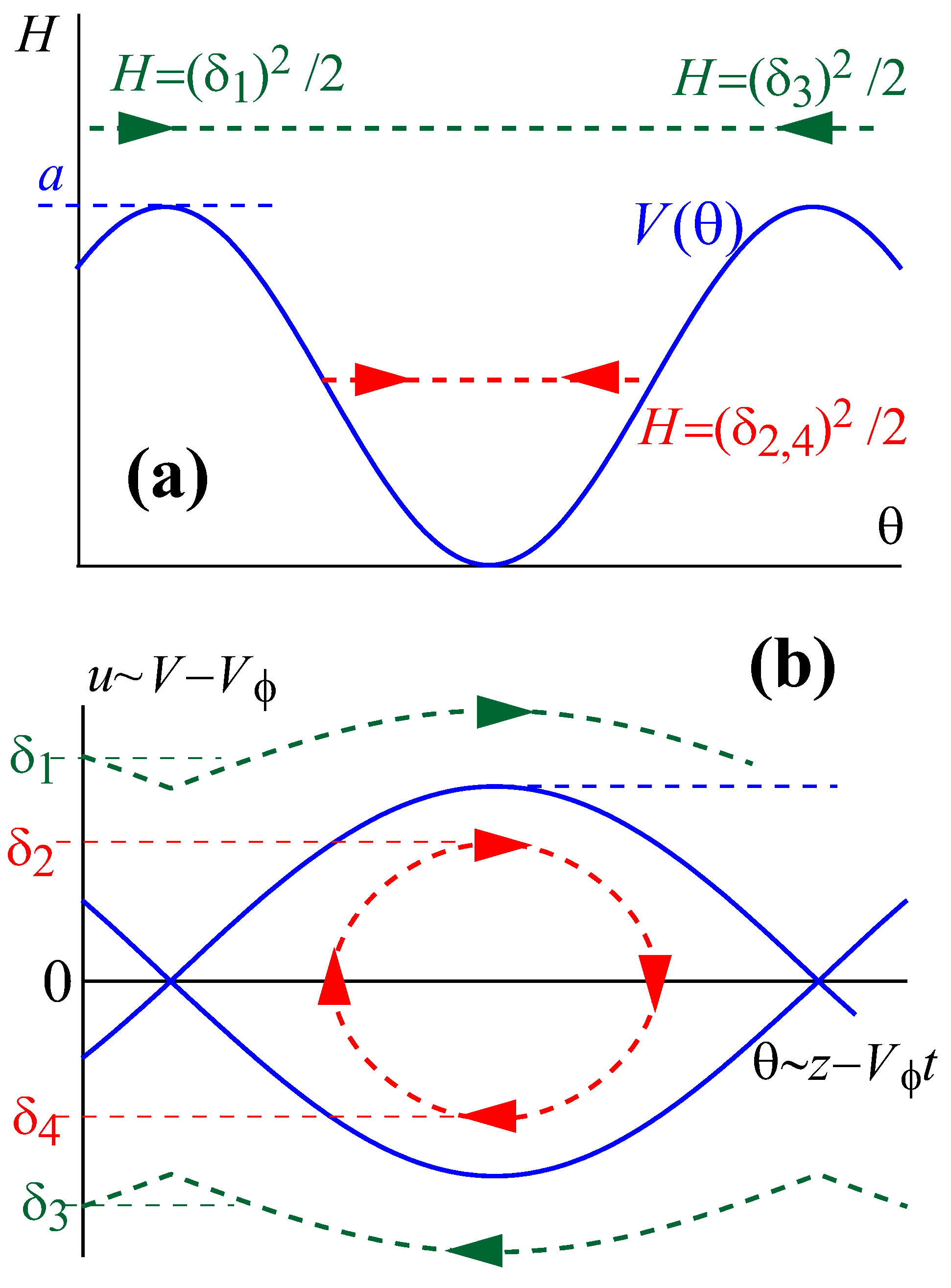
Here, we stay within the simple standard model and treat the motion of a particle as prescribed by the aforementioned Newtonian formalism. Figure 2 illustrates the corresponding phase plane motion along lines H = c o n s t , where electrons with H > a move along infinite trajectories, whereas particles with H < a perform finite oscillations inside of the separatrix (“bucket”).
As a next step, we should consider that the amplitude a of the effective potential P θ in Equation (6) depends on the electron phase. Actually, it is mentioned previously that the wave pulse is so short that the characteristic scale of the inhomogeneity of the wave field is comparable to its wavelength (Figure 1). This corresponds to the situation where the effective potential P θ is noticeably inhomogeneous on the scale θ = 2 π . Figure 3 illustrates the behavior of particles with different initial velocities V 0 (different mismatches δ = ( V 0 V ϕ ) / V ϕ ) in the case of the zero slippage factor ε (i.e., when V g r = V ϕ ). At the beginning of the interaction process, when u τ = 0 = δ , all particles are far from the wave pulse ( θ L ), and therefore, we should put a 0 and P 0 in Equation (6). Thus, in the adiabatic approximation, trajectories of electrons H = c o n s t are described by the following formula:
u 2 2 + P θ = δ 2 2
Let us consider two particles with u τ = 0 = δ 1,2 > 0 ( V 0 > V ϕ ) that catch up with the wave pulse (they approach it in Figure 3a on the left). The particle “1” with a relatively high velocity of δ 1 2 / 2 > a 0 passes through the wave pulse without reflection, and thus, its final velocity coincides with the initial one of u 1 = δ 1 . In contrast, the particle “2” with a lower velocity of δ 2 2 / 2 < a 0 cannot overcome the potential barrier at a certain point inside the pulse. Thus, it is reflected from the wave pulse. According to Equation (7), its final normalized velocity is u 2 = δ 2 . A similar situation occurs for two particles with initial velocities lower than the group velocity of the wave pulse (that is, with negative detuning u τ = 0 = δ 3,4 < 0 ). They approach the wave pulse from the right (Figure 3b), and the particle “3” (which has a large mismatch of δ 3 2 / 2 > a 0 ) passes through the pulse with no change in the normalized velocity u 3 = δ 3 whereas the particle “4” with a relatively small mismatch of δ 4 2 / 2 < a 0 is reflected from it (Figure 3c,d) with the final normalized velocity u 4 = δ 4 .
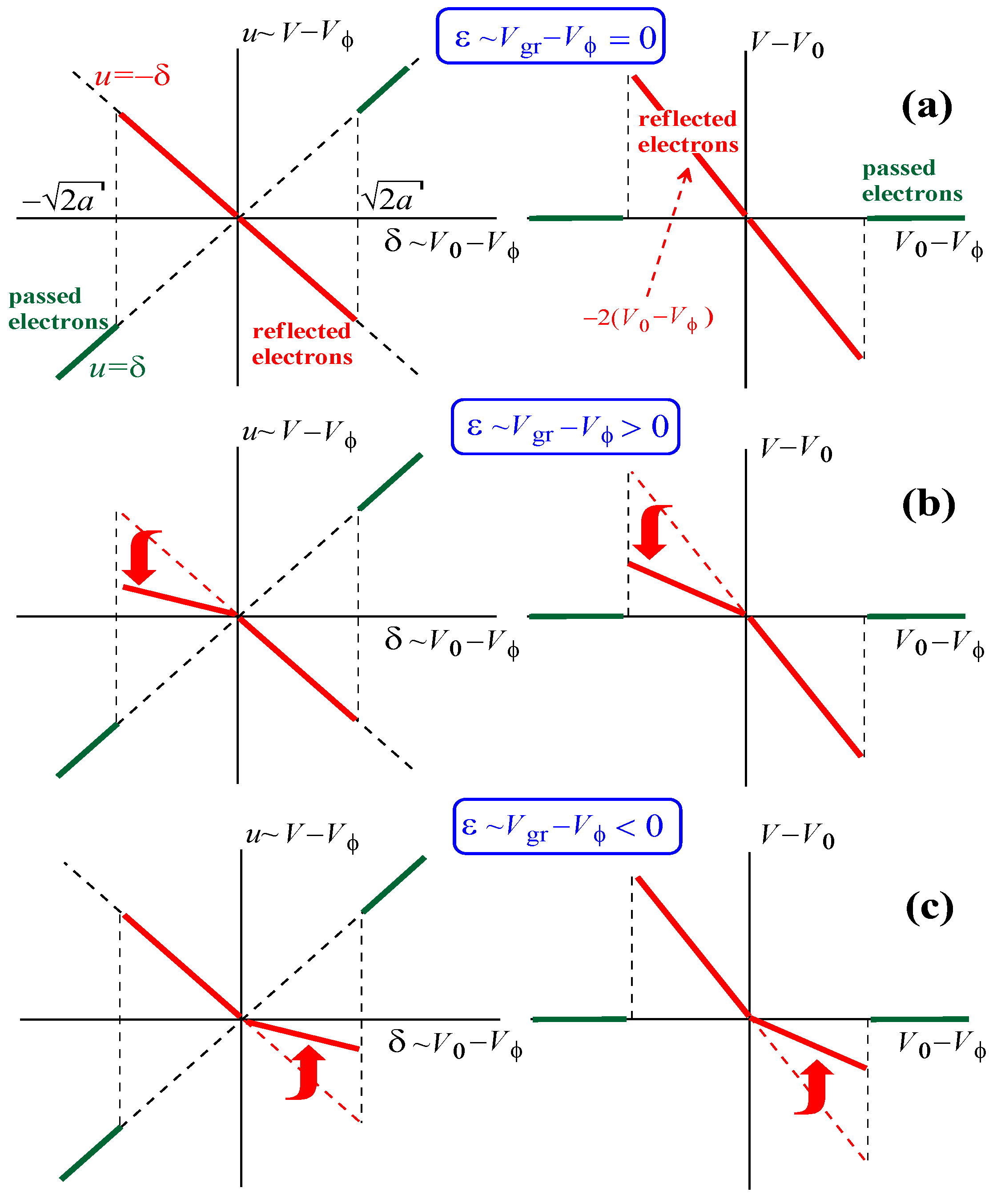
Hence, given the zero slippage factor V g r = V ϕ , the adiabatic approximations give the following result for the final (at the end of the interaction with the wave pulse) normalized velocity (Figure 4a):
u f i n = δ , δ < 2 a 0 ; δ , δ > 2 a 0
This corresponds to the following dependence of the final electron velocity V f i n on the initial velocity (Figure 4a):
V f i n V 0 = 2 ( V 0 V ϕ ) , V 0 V ϕ V ϕ < 2 a 0 ; 0 , V 0 V ϕ V ϕ > 2 a 0
If we consider interaction with the wave pulse of an electron flow composed of particles of different velocity fractions with the uniform distribution function f ( V 0 ) = c o n s t in the close-to-resonance range of velocities V 0 V ϕ , then for zero slippage factor V g r = V ϕ , we get a zero average change in electron velocity:
V f i n V 0 d V 0 = 0
Actually, the far-from-resonance electrons (with relatively large δ ~ V 0 V ϕ ) pass through the wave pulse, and their final velocities coincide with the initial ones. As for electrons being relatively close to the resonance, they are reflected from the potential barrier formed by the wave field. As a result, particles with V 0 > V ϕ are decelerated down to V f i n < V ϕ , whereas particles with V 0 < V ϕ are accelerated up to V f i n > V ϕ . However, due to the symmetry of these two processes (Figure 4a), the deceleration of relatively fast ( V 0 > V ϕ ) close-to-resonance particles is fully compensated by the acceleration of relatively slow ( V 0 < V ϕ ) close-to-resonance particles.

2.3. Motion of Electrons on the Phase Plane with Non-Zero Slippage

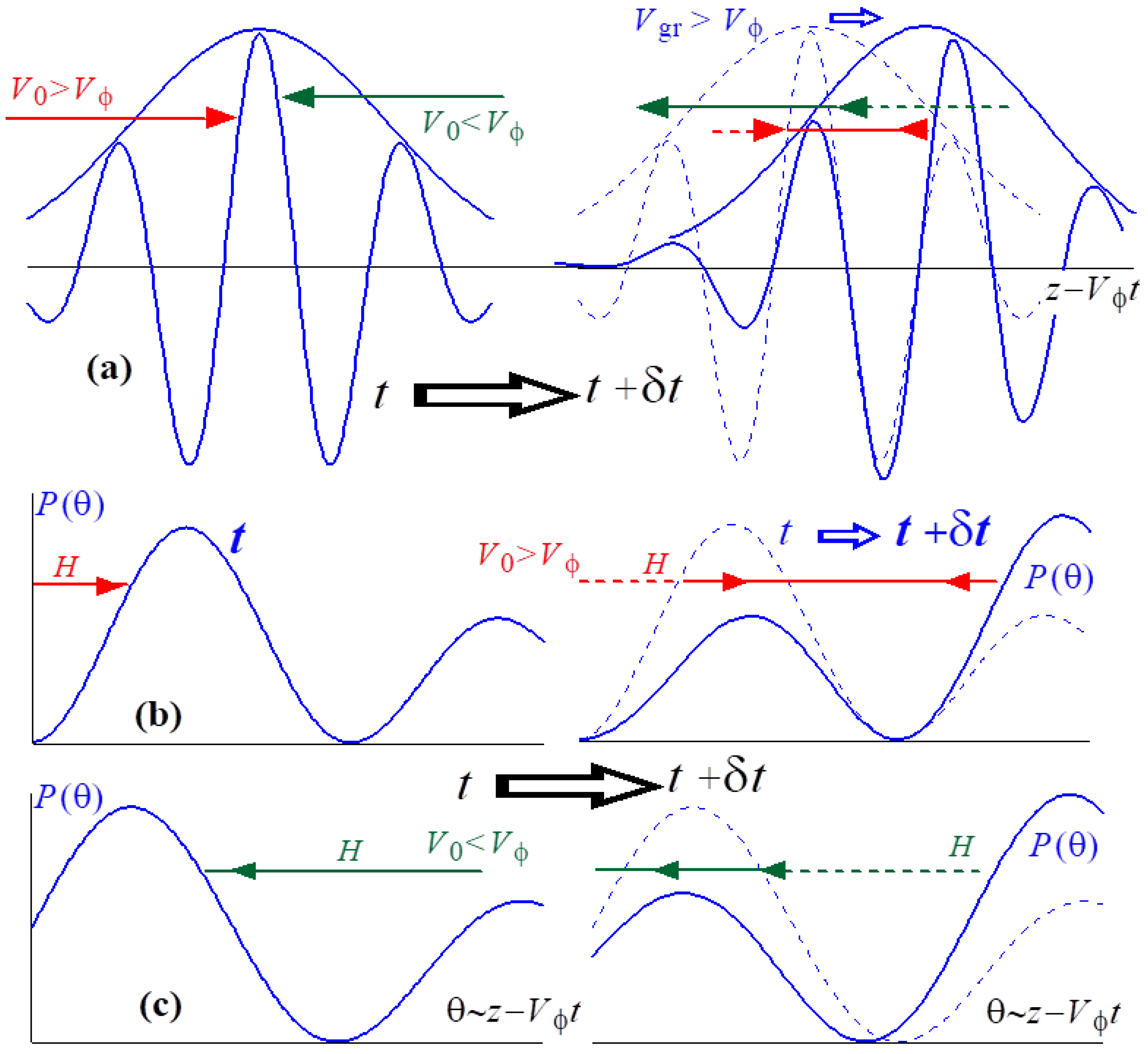
According to numerical calculations described in detail in Section 3, the symmetry shown in Figure 4a is broken when the slippage factor is nonzero, i.e., when ε = ( V g r V ϕ ) / V ϕ 0 . Figure 5 illustrates this effect for when the group velocity of the wave slightly exceeds the phase velocity, i.e., ε > 0 . In this case, the maximum of the potential P θ can be expressed with the following equation:
a = a 0   e x p ( θ ε τ ) 2 L 2
In addition, P θ slowly shifts in the positive direction of the axis θ ~ z V ϕ t . Let us consider the behavior of two particles with V 0 > V ϕ and V 0 < V ϕ that are relatively close to the electron wave resonance δ < 2 a 0 . These electrons are analogous to the “symmetrical” particles with δ = δ 2 and δ = δ 4 shown in Figure 3, and therefore, when ε = 0 , they should be reflected from the wave pulse. When ε > 0 , the symmetry is broken because, with respect to the coordinate θ ~ z V ϕ t , the envelope of the wave pulse (Figure 5a) and the potential relief P θ (Figure 5b,c) slowly move forward. Therefore, “from the point of view” of the faster ( V 0 > V ϕ , δ > 0 ) particle (Figure 5b), the potential relief P θ moves co-directionally to the movement of this particle with a low relative velocity of
d d τ θ ε τ = δ ε .
Such a motion of the potential relief does not fundamentally change the particle motion pattern so that it is reflected from the barrier slowly escaping from it. In contrast, “from the point of view” of the slower ( V 0 < V ϕ , δ < 0 ) particle (Figure 5c), the relief P θ moves counter-directionally to this particle, and the relative velocity of this motion with respect to this particle, expressed as
d d τ θ ε τ = δ + ε ,
is higher compared to the previous case of the slower particle. As a result of this rapid movement of the potential barrier towards the particle, there is a possibility of a non-adiabatic effect of the electron overcoming the barrier (Figure 5c).
Thus, in the case of a positive slippage factor, i.e., when ε > 0 , the dependence u ( δ ) becomes non-symmetrical for the close-to-resonance electrons ( δ < 2 a 0 ). All faster ( δ > 0 ) close-to-resonance electrons are reflected from the wave pulse (and thereby decelerated) similar to the case of ε = 0 so that u f i n =   δ for all electrons (compare Figure 4a,b). As for the slower ( δ < 0 ) close-to-resonance particles, there are two scenarios for their interaction with the wave pulse, namely, such particles can either be reflected by the wave pulse (in this case, u f i n =   δ , similar to the case of ε = 0 ) or pass through the pulse (in this case, the final velocity is equal to the initial one, u f i n =   δ ).
Here, we should note that when we talk about different electrons with the same normalized initial velocity u τ = 0 = δ (i.e., about the different behavior of these electrons in the process of their interaction with an electromagnetic pulse), we mean the following. Any velocity fraction of the electron flow consists of particles possessing the same normalized initial velocity δ but different initial phases θ τ = 0 = θ 0 with respect to the wave (in other words, different initial axial coordinates h 0 z 0 = θ 0 ). More precisely, the initial phases of the particles are randomly distributed within the interval
θ 0,1 < θ 0 < θ 0,2 .
The range of these initial phases ( θ 0,1 , θ 0,2 ) was chosen for the following reasons. First, the electrons are considered, which, at the initial moment of time, are located away from the center of the wave pulse, that is, in the region of an almost zero wave field; according to Equation (4), this means that θ 0 L . Second, the interval ( θ 0,1 , θ 0,2 ) should cover particles with all possible phases of entry into the field of the wave pulse. Practically, this means that if we introduce the final (at the end of the interaction with the wave pulse) electron velocity of a given velocity fraction δ averaged over all phases as
u f i n δ = 1 θ 0,2 θ 0,1 θ 0,1 θ 0,2 u f i n δ d θ 0 ,
then the result of such averaging should not change when the interval of the initial phases is shifted
θ 0,1 , θ 0,2 ( θ 0,1 + 2 π n , θ 0,2 + 2 π n )
where n is any integer.
Therefore, the existence of these two scenarios for the interaction of particles from a slower ( δ < 0 ) close-to-resonance velocity fraction (either u f i n =   δ or u f i n =   δ ) means that the averaged (over electrons with all initial phases) normalized final velocity u f i n ( δ ) for electrons of these fractions is somewhere between δ < u f i n ( δ ) < δ (Figure 4b). Consequently, the deceleration of the faster ( δ > 0 ) close-to-resonance electrons due to their reflection from the wave pulse is not compensated by the reflective acceleration of the slower ( δ < 0 ) close-to-resonance particles. As a result, for the uniform distribution function f ( V 0 ) = c o n s t , the averaged (over all velocity fractions) change in electron velocity is negative (Figure 4b), i.e.,
V ¯ V 0 d V 0 < 0 .
This means that for a positive slippage factor, i.e., ε = V g r V ϕ V ϕ > 0 , the electron flow passes a part of its energy to the wave pulse, and therefore, it amplifies this pulse. In contrast, if the slippage factor is negative, i.e., ε < 0 , then the symmetry is broken due to the incomplete reflection from the wave pulse of the faster ( V 0 > V ϕ , δ > 0 ) particles (Figure 4c), and in this case, the electron flow absorbs the energy of the wave pulse
V ¯ V 0 d V 0 > 0

3. Simulation of Electrons with a Short Adjusted Wave Pulse

3.1. Normalized Equations

In the equations used for our simulations, we introduced the following new variables:
τ n = a 0 τ ,   u n = u / a 0 ,   δ n = δ / a 0 ,   ε n = ε / a 0 .
In this case, Equations (3) and (4) are transformed as follows:
d u n d τ n = e x p ( θ ε n τ n ) 2 L 2 c o s θ ,   d θ d τ n = u n ,   u n τ n = 0 = δ n .
The reflection of electrons from the potential barrier looks as follows (Figure 6):
δ n < 2 .
At any fixed initial velocity of particles δ n , we solve this problem for an ensemble of electrons having different initial phases θ 0 = h 0 z 0 = θ 0 . Their values are determined by the sign of the difference
δ n ε n ~ V 0 V g r .
If this difference is positive, then the initial phases θ 0 should be negative; this corresponds to the case where the electrons catch up to the wave pulse. In the opposite case, phases θ 0 should be positive. Moreover, the absolute values of initial phases should be big enough, i.e., θ 0 L , to model the situation where the initial positions of all electrons correspond to a close-to-zero wave field.
In simulations, we studied the motion of an ensemble of electrons with the same initial normalized velocity δ n and with a sufficiently large set of initial phases θ 0 describing all possible scenarios of the interaction of particles with a wave pulse. We solved Equation (12) for such electron ensembles corresponding to various velocity fractions of δ n using the standard Runge–Kutta procedure and found the averaged (over all initial phases) final (after passing through the whole wave pulse) velocity u n , f i n ¯ = u n θ 0 for electrons from the fraction δ n , and we also found plot dependences u n , f i n ¯ ( δ n ) analogous to the schematic pictures shown in Figure 4. In these simulations, we assumed that the electron wave energy exchange did not effect the amplitude and shape of the wave pulse; this corresponds to the situation when the electron density is so small that the result of such an energy exchange for the characteristic interaction time of a particle with a wave pulse turns out to be much less than the total energy of the wave pulse.

3.2. Violation of the Symmetry of the Interaction of Different Electron Fractions with a Wave Pulse with Small Slippage Factors

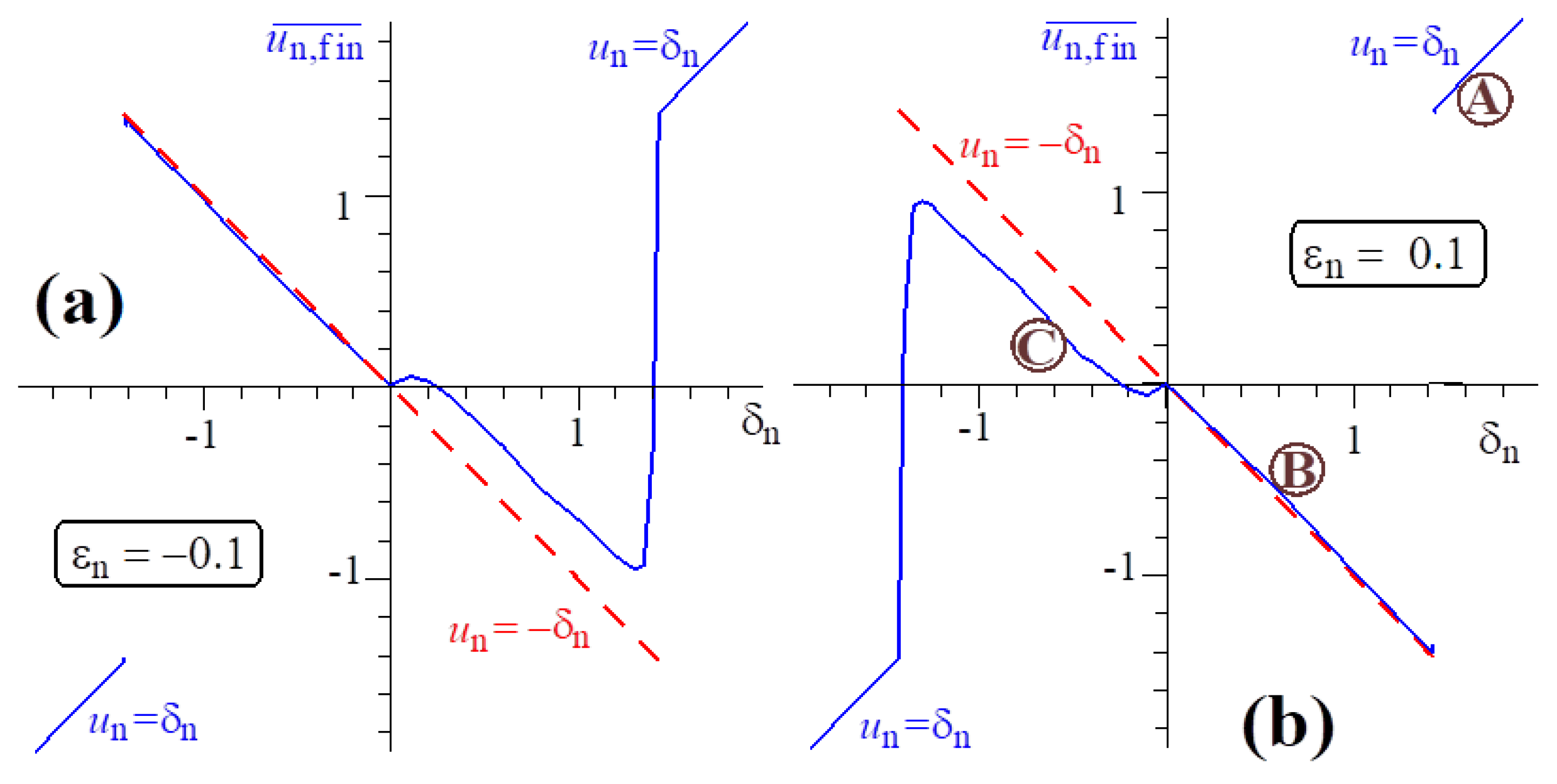
Figure 6 compares the cases of the slippage parameters ε n = 0.1 and ε n = 0.1 . In these simulations, as an example, we considered the case where the normalized length of the wave pulse, 2L, corresponds to eight wave circles, but the results were almost independent on this length. Naturally, we saw two mutually symmetric pictures. For negative ε n , the symmetry of the dependence u n , f i n ¯ ( δ n ) was disturbed in the range where δ n are positive and correspond to reflections 0 < δ n < 2 , whereas for positive ε n , we saw the same perturbations in the range 2 < δ n < 0 . (compare with Figure 4). Evidently, in the case illustrated in Figure 6a,
u n , f i n ¯ δ n δ n d δ n ~ V ¯ V 0 d V 0 > 0 .
Therefore, the whole electron ensemble on average absorbs the wave energy. In contrast, the case in which ε n > 0 , which is illustrated in Figure 6, describes the situation where the electron ensemble passes the energy to the wave:
u n , f i n ¯ δ n δ n d δ n ~ V ¯ V 0 d V 0 < 0 .
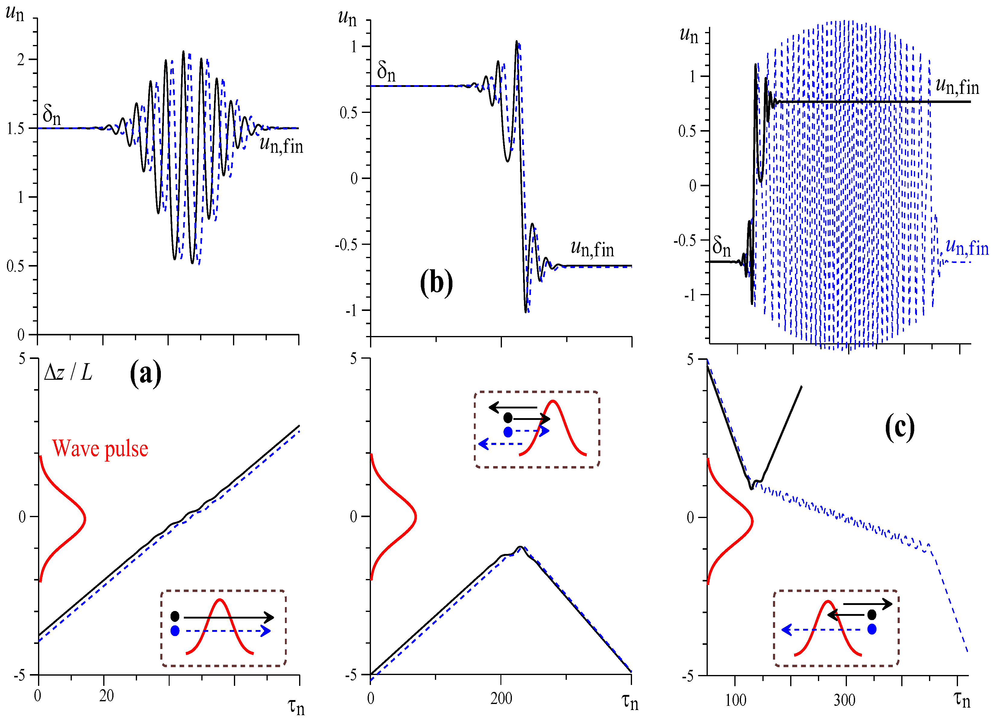
Figure 7 illustrates dynamics of motion of different electrons with normalized initial velocities corresponding to points a, b, and c, which are shown in the circles in Figure 6b (where ε n = 0.1 ). Here, we introduced the normalized position of a particle with respect to the center of the wave pulse:
Z = θ ε n τ n L .
The case of the normalized initial velocities δ n = 1.5 (Figure 7a) corresponds to the case where all electrons pass through the potential barrier created by the wave (point A in Figure 6b). The simulations predicted such behavior for all particles. The next case, in which δ n = 0.7 (Figure 7b), corresponds to the case where all electrons have positive normalized initial velocities δ n corresponding to the reflection from the potential barrier (point B in Figure 6b). The simulations predicted again the same behavior for all particles from this velocity fraction.
Finally, the case in which δ n = 0.7 (Figure 7c) corresponds to the case where all electrons have negative normalized initial velocities δ n corresponding to the reflection from the potential barrier (point C in Figure 6b). Here, the simulations predicted two kinds of behavior for the particles with different initial phases with respect to the wave pulse. The “proper” particles (solid black curves in Figure 7c) are really reflected, and at the end of the electron wave interaction, their velocity is u n , f i n = δ n . However, there are also the “wrong” particles (dashed blue curves in Figure 7c) that pass through the potential barrier, and their final normalized velocity is approximately equal to the initial one, u n , f i n = δ n . Because the difference between δ n and the calculated value of u n , f i n ¯ ( δ n ) in this case is ~0.2 (Figure 6c), it is easy to calculate that the share of the “wrong” particles in this case is close to 15%.

3.3. Large Slippage Factors and the “Non-Resonant” Reflection

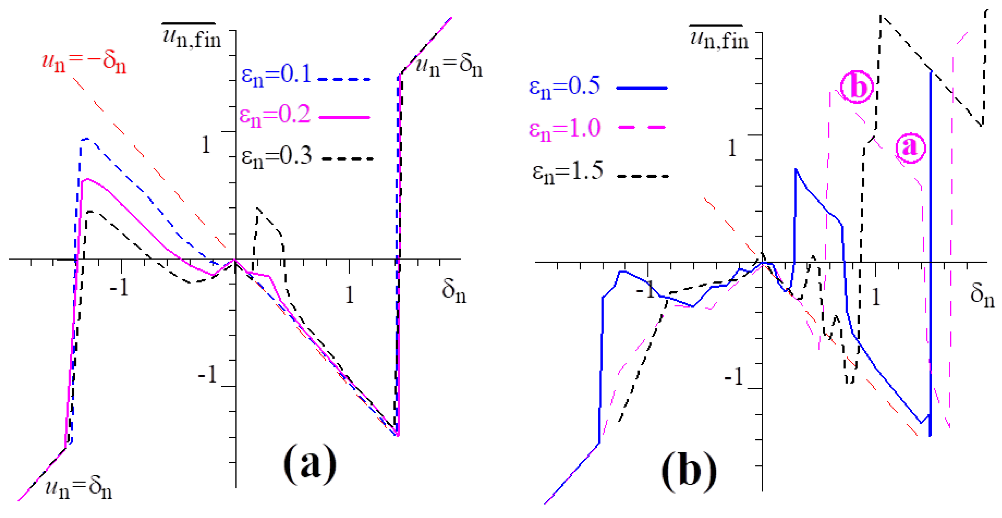
Figure 8a illustrates how the perturbations in the symmetry of the function u n , f i n ¯ ( δ n ) depends on the values of the slippage parameter ε n where this parameter is small, i.e., ε n 1 . On one hand, an increase in ε n results in an increase in non-symmetry between electron from the reflection range δ n < 2 , as the differences between δ n and the calculated value of u n , f i n ¯ ( δ n ) increase in the region of negative δ n .This is easily explained by the increase in the degree of non-adiabatic interaction of particles with a potential barrier with an increase in the slippage factor. Thus, for ε n = 0.3 in the region of mismatches corresponding to the reflection of particles ( 2 < δ n < 0 ), the characteristic value of the final normalized particle velocity u n , f i n ¯ δ n is close to zero. This corresponds to the fact that the share of “wrong” particles (which, instead of reflecting, pass through the potential barrier) becomes close to 50%.
On the other hand, at ε n = 0.3, we see a certain small “outlier” (i.e., deviation from the “correct” dependence u n , f i n ¯ δ n = δ n ) in the region of positive normalized initial velocities δ n corresponding to the reflections of particles from the potential barrier. This deviation takes place in areas close to the value of the normalized initial velocity
δ n = ε n .
which corresponds to the fraction with “zero” slippage of electrons relative to the wave pulse. Note that Equation (12) does not allow us to calculate the situation exactly as described by the condition of Equation (14), but we can make calculations near the initial velocity. It is clear that this “outburst” somewhat compensates for the effect of the asymmetry of electrons with positive and negative mismatches of δ n .
With a further increase in the slippage factor, the harmony of the electron asymmetry pattern is destroyed (Figure 8b). On one hand, the non-adiabaticity of the motion of particles with negative δ n increases, and the dependence corresponding to the full reflection u n , f i n ¯ δ n = δ n at ε n = 1.5 is transferred into the dependence u n , f i n ¯ δ n = δ n corresponding to the passage of particles through the wave pulse without a change in velocity. On the other hand, we observed the growth of the “outburst” in the area around the point δ n = ε n . Evidently, the negative effect of this “outburst” begins when resonant electrons with relatively large mismatches δ n corresponding to a relatively large perturbation of particle velocities by the wave field are involved in it, i.e., when
δ n = ε n ~ 1 .
The physical reasons explaining this “outburst” are as follows. It describes the non-resonant reflection from the wave pulse of particles that are relatively far from the electron wave resonance. In fact, this is the reflection of particles not from the potential barrier described in Figure 3, but from the wave pulse itself under the influence of an averaged pondermotive force (in fact, the Miller force [19]), pushing particles into the region of a weaker wave field.
Let us consider particles with normalized initial velocities δ n ε n when the slippage factor ε n is large. Then, they are far enough away from resonance with the wave that their phases change rapidly, as follows:
θ = θ 0 + 0 τ n u n d τ n θ 0 + δ n τ n
Next, we carried out a standard procedure for calculating the Miller force, representing the phase and the normalized velocity of the particle as the sum of the slow and small oscillating components as follows:
u n = U n + u ~ , θ = θ 0 + 0 τ n U n d τ n + θ ~
For a rapidly oscillating phase from Equation (12) we obtained the following expression:
θ ~ g U n 2 cos θ 0 + 0 τ n U n d τ n θ ~ g ε n 2 cos θ 0 + 0 τ n U n d τ n
Here,
g = e x p θ ε n τ n 2 L 2 ,
and we assume that the slow normalized velocity U n is always close to the level U n δ n ε n . Then, the slow component of the electron velocity is described by the following expression:
d U n d τ n = cos θ 0 + 0 τ n U n d τ n × g θ ~ θ ~
Having considered Equation (15), after the averaging we obtain:
d U n d τ n = 1 4 ε n 2 g 2 θ ~
Then, we consider the following formula:
g 2 θ ~ = 1 U n ε n × g 2 τ n
As a result, Equation (17) reduces to the following equation:
U n ε n × d U n d τ n = 1 4 ε n 2 g 2 τ n
This equation is easily integrated due to the fact that the particle starts from the region of the zero field ( g 2 = 0 ):
U n ε n 2 δ n ε n 2 = g 2 2 ε n 2
Because the particle ends its interaction with the wave pulse in the region of the zero field, its final normalized velocity is determined by the expression
U n ε n = ± δ n ε n .
One of the solutions of Equation (20) corresponds to the passage of a wave pulse by a particle without changing the velocity, i.e.,
U n = δ n ,
but another solution,
U n = 2 ε n δ n ,
Describes the “reflection” of the normalized velocity from the level U n = ε n . Actually, if the initial normalized velocity of the particle
U n 0 = δ n = ε n + ( δ n ε n )
exceeds the level U n = ε n by an amount ( δ n ε n ) , then the final velocity is below this level by the same amount, i.e.,
U n = 2 ε n δ n = ε n ( δ n ε n ) .
Similar considerations are true for a particle whose initial normalized velocity is below the level of U n = ε n . As an example of such particle behavior in the process of non-resonant reflection from the wave pulse, Figure 9 shows the calculation results at ε n = 1 for two particles with initial normalized velocities δ n = ε n ± 0.3 .
It is clear that in order to realize non-resonant reflection, it is necessary that Formula (19) should “allow” the particle to reach the velocity level U n = ε n . Therefore, the reflection is realized only for particles whose mismatches are close enough to the slippage factor
δ n = ε n ± 1 2 ε n .
Note that due to the symmetry of the non-resonant reflection process with respect to particles with δ n larger and smaller than ε n on average for all fractions involved in non-resonant reflection, it does not lead to energy exchange with the wave pulse. Indeed, if U n is described by Formula (21), then the average velocity change for particles being in the region of non-resonant reflection ε n α < δ n < ε n + α is zero:
ε n α ε n + α U n δ n δ n d δ n = 0 .
At the same time, the non-resonant reflection of particles “spoils” the “proper” statistics for all velocity fractions (the “proper” perturbation in symmetry of the dependence u n ¯ ( δ n ) ).

4. Discussion and Conclusions

In conclusion, we can assert that the considered effect of the perturbation of the symmetry of the kinetic resonant interaction of electrons with different velocities and a short adjusted wave pulse is able to explain the effect of formation and subsequent amplification by an electron flow with a large velocity spread of powerful pulses of quasi-monochromatic electromagnetic radiation known as space plasma. Obviously, such an amplification of wave pulses should be associated with the extraction of the kinetic energy of electron flow particles by these pulses. For an electron flow with a wide velocity spread, when the number of “fast” and “slow” (with respect to the wave phase velocity) electrons in the resonant velocity band is the same, there must be a mechanism that ensures the asymmetry of the energy exchange of fast and slow electrons with the wave. In other words, a situation should be realized when fast particles, on average, give more energy to the wave than slow electrons absorb. This is exactly the mechanism described in this paper. We see that this effect is realized when resonant particles whose translational velocities are close to the phase velocity are near the group synchronism with the wave pulse. For the exact group synchronism, the interaction of the “fast” and “slow” resonant electrons with the wave is symmetrical, and as a result, there is no energy exchange between the electron flow and the wave (Figure 4a and Figure 6). However, this symmetry disappears if there is a small slippage between the phase and the group velocities (Figure 4b,c and Figure 6). In particular, if the group velocity of the wave should slightly exceed its phase velocity, then the electron stream gives energy to the wave. This paper also describes the disappearance of this effect with an increase in the slippage factor of resonant electrons relative to the wave pulse.
Note that the effect described in this paper exists in a fundamentally non-linear regime. The amount of kinetic energy of electrons transmitted to the wave per unit of time increases with the increase in the power of the electron pulse. Actually, it is evident that the total electron velocity losses are determined by the area that the reflected electrons “occupy” in Figure 3, represented as
δ V ¯ Σ = V ¯ V 0 d V 0 δ r e f 2 ,
where δ r e f = 2 a is the maximal mismatch corresponding to the reflected electrons. It is also evident that the number of electrons of the “reflected” fractions that “meet” with the pulse per unit of time is proportional to the difference between the group velocity and the characteristic translational velocity of the particles of the reflected fractions as follows:
d N ( V 0 V g r ) d t δ r e f d t
If the change in the electron energy is small (and the change in the kinetic energy of a particle is proportional to the change in the velocity), then the energy of the wave pulse increases in the time as follows:
d W δ V ¯ Σ d N δ r e f 3 d t a 3 / 2 d t
Because W l a 2 (here, l is the wave pulse length), the effect described in this paper corresponds to the following estimated equation describing the growth of the wave pulse amplitude and of the total energy in the pulse:
d a d t a l , d W d t W l 3 / 4
Thus, although the average (over all velocity fractions) change in electron energy resulting from the symmetry-breaking effect between fast and slow particles described in the paper weakly depends on the duration of the wave pulse, the corresponding growth rate of the amplitude and energy of the wave pulse increases with the shortening of the pulse length. This may be a possible explanation for the observation of short and powerful microwave pulses in space plasma. At the same time, such non-linear radiation process can be observed in modern synchrotron and undulator radiation sources (including the short-wavelength free-electron lasers), where the velocity spread in the operating electron bunches is typically very large on the scale of the resonant electron wave interaction band.
It is clear that the described effect was studied in this paper on the basis of the simplest model of the interaction of electrons with a wave pulse of a fixed structure. It is necessary to consider influences on the structure of the wave pulse for a more correct description of the energy exchange between an electronic ensemble and a wave. At the same time, it is clear that such an approach is quite acceptable as the first step in describing such a nonlinear gain (for example, for a relatively low charge density in the electron flow).

Author Contributions

Conceptualization, P.B. and A.S.; methodology, P.B. and A.S.; software, V.K. and A.S.; formal analysis, V.K. and A.S.; investigation, P.B., V.K., and A.S.; writing—original draft preparation, V.K. and A.S.; writing—review and editing, P.B. and A.S.; project administration, P.B. All authors have read and agreed to the published version of the manuscript.

Funding

This research was supported by the Russian Science Foundation, project no. 20-12-00268 (Section 2), as well as by the State Assignment of the Institute of Applied Physics RAS, project no. 0030-2021-0001 (Section 3).

Data Availability Statement

Not applicable.

Conflicts of Interest

The authors declare no conflict of interest.

References

  1. Zhou, C.; Li, W.; Thorne, R.M.; Bortnik, J.; Ma, Q.; An, X.; Zhang, X.-J.; Angelopoulos, V.; Ni, B.; Gu, X.; et al. Excitation of dayside chorus waves due to magnetic field line compression in response to interplanetary shocks. J. Geophys. Res. 2015, 120, 8327. [Google Scholar] [CrossRef]
  2. Hallinan, G.; Antonova, A.; Doyle, J.G.; Bourke, S.; Brisken, W.F.; Golden, A. Rotational modulation of the radio emission from the M9 dwarf TVLM 513–46546: Broadband coherent emission at the substellar boundary? Astrophys. J. 2006, 653, 690. [Google Scholar] [CrossRef]
  3. Stepanov, A.; Zaitsev, V. On the Origin of Persistent Radio and X-ray Emission from Brown Dwarf TVLM 513-46546. Universe 2022, 8, 77. [Google Scholar] [CrossRef]
  4. Hankins, T.H.; Eilek, J.A. Radio emission signatures in the crab pulsar. Astrophys. J. 2007, 670, 693. [Google Scholar] [CrossRef] [Green Version]
  5. Yang, H.; Dang, S.; Zhi, Q.; Shang, L.; Xu, X.; Zhang, D.; Xiao, S.; Zhao, R.; Dong, A.; Liu, H.; et al. Single Pulse Studies of PSR B0950+08 with FAST. Universe 2023, 9, 50. [Google Scholar] [CrossRef]
  6. Mikhailovskii, A.B. Theory of plasma instabilities. In Instabilities of a Homoegeneous Plasma; Consultants Bureau: New York, NY, USA; London, UK, 1974. [Google Scholar]
  7. Melrose, D.B. Instabilities in Space and Laboratory Plasmas; Cambridge University Press: Cambridge, UK, 1989. [Google Scholar]
  8. Bespalov, P.A.; Savilov, A.V. Amplification of a slipping quasi-monochromatic wave pulse by an electron flow with a wide velocity spread. Phys. Plasmas 2021, 28, 093303. [Google Scholar] [CrossRef]
  9. Bespalov, P.A.; Savina, O.N. An excitation mechanism for discrete chorus elements in the magnetosphere. Ann. Geophys. 2018, 36, 1201. [Google Scholar] [CrossRef] [Green Version]
  10. Bespalov, P.A.; Savina, O.N. An excitation mechanism of electromagnetic pulses by relativistic electrons in the brown dwarfs rarefied magnetosphere. Mon. Not. R. Astron. Soc. 2018, 480, 4761. [Google Scholar] [CrossRef]
  11. Bespalov, P.A.; Savina, O.N. Excitation of the main giant pulses from the Crab pulsar. Mon. Not. R. Astron. Soc. 2020, 498, 2864. [Google Scholar] [CrossRef]
  12. Bespalov, P.A.; Savina, O.N.; Cowley, S.W.H. The beam pulse amplifier in space and laboratory plasmas. Results Phys. 2020, 16, 103004. [Google Scholar] [CrossRef]
  13. Helliwell, R.A. Whistlers and Related Ionospheric Phenomena; Stanford University Press: Stanford, CA, USA, 1965; Chapter 3. [Google Scholar]
  14. Stix, T. Waves in Plasma; American Institute of Physics: New York, NY, USA, 1992; Chapter 2. [Google Scholar]
  15. Bespalov, P.A.; Trakhtengerts, V.Y. Cyclotron instability of the Earth radiation belts. In Reviews of Plasma Physics; Consultants Bureau: New York, NY, USA, 1986; Volume 10, pp. 155–292. [Google Scholar]
  16. Ginzburg, N.S.; Sergeev, A.S.; Novozhilova, Y.V.; Zotova, I.V.; Rosenthal, R.M.; Phelps, A.D.R.; Cross, A.W.; Aitken, P.; Shpak, V.G.; Yalandin, M.I.; et al. Experimental observation of Cherenkov superradiance from an intense electron bunch. Opt. Commun. 2000, 175, 139–146. [Google Scholar] [CrossRef]
  17. Ginzburg, N.S.; Golovanov, A.A.; Zotova, I.V.; Malkin, A.M.; Tarakanov, V.P. Undulator superradiance effect and its applicability for the generation of multimegawatt terahertz pulses. J. Exp. Theor. Phys. 2014, 119, 632–640. [Google Scholar] [CrossRef]
  18. Kuzikov, S.V.; Savilov, A.V. Regime of “multi-stage” trapping in electron masers. Phys. Plasmas 2018, 25, 113114. [Google Scholar] [CrossRef]
  19. Lundin, R.; Guglielmi, A. Ponderomotive forces in cosmos. Space Sci. Rev. 2006, 127, 1–116. [Google Scholar] [CrossRef]
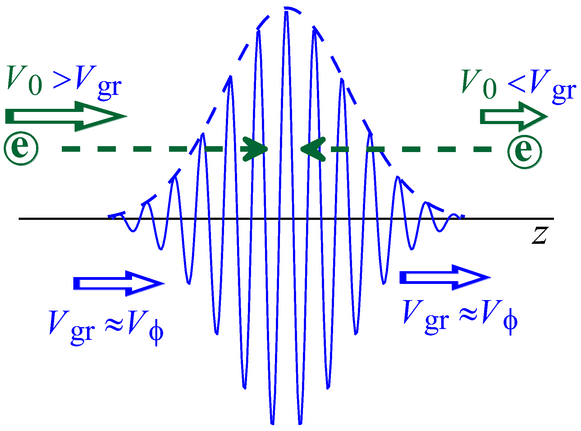
Figure 1. Tracks of electrons with different initial velocities with respect to the wave pulse.
Symmetry 15 00838 g001
Figure 2. Potential relief P θ formed by the wave field (a) and motion characteristics of electrons with various initial velocities on the phase plane (b) in the manner of a constant wave amplitude.
Symmetry 15 00838 g002
Figure 3. Motion of different electrons with V 0 > V ϕ (a) and V 0 < V ϕ (b) in the wave pulse where the group velocity of the wave coincides with its phase velocity. The illustration of the motion of these electrons is in terms of the potential relief P θ formed by the wave field (c) and in terms of the phase plane (d).
Symmetry 15 00838 g003
Figure 4. Illustrations of the dependence of the final (at the end of the interaction of a particle with the wave pulse) electron velocity on its initial velocity at various slippage factors: ε = 0 (a), ε > 0 (b), and ε < 0 (c). Left plots illustrate the dependence of the normalized electron velocity u versus its initial value δ . Right plots illustrate the same dependences in terms of the change in the velocity V V 0 versus the initial velocity V 0 .
Symmetry 15 00838 g004
Figure 5. (a) Evolution of the field of the wave pulse when V g r > V ϕ as well as the motion of faster ( V 0 > V ϕ ) and slower ( V 0 < V ϕ ) electrons through the wave pulse. (b,c) Motion of the faster and slower electrons on the background of the evolution in the time of the potential relief P θ formed by the wave field.
Symmetry 15 00838 g005
Figure 6. Averaged final normalized velocity u n , f i n ¯ of electrons versus their initial normalized velocity δ n for normalized slippage parameters ε n = 0.1 (a) and ε n = 0.1 (b). Points A, B, and C in Figure 6b correspond to the parameters of the calculations illustrated in Figure 7a–c, respectively.
Symmetry 15 00838 g006
Figure 7. Dynamics of motion of different electrons with normalized initial velocities δ n when ε n = 0.1 . Normalized velocity of the particles u n (top plots) and their normalized position are shown with reference to the center of the wave pulse Z (bottom plots) versus the normalized time τ n . In the bottom plots, the distribution of the wave pulse is also shown. (a) Normalized initial velocities δ n = 1.5 corresponds to the case in which all electrons pass through the potential barrier created by the wave pulse (point A in Figure 6b). (b) Initial velocities δ n = 0.7 corresponds to the case in which all electrons are reflected from the wave pulse (point B in Figure 6b). (c) Ininitial velocities δ n = 0.7 corresponds to the case in which a particle can both be reflected and pass the wave pulse (point C in Figure 6b).
Symmetry 15 00838 g007
Figure 8. The averaged final normalized velocity u n ¯ of electrons versus their initial normalized velocity δ n for small slippage parameters ( ε n = 0.1 ,   0.2 ,   a n d   0.3 ) (a) and for large slippage parameters ( ε n = 0.5 ,   1.0 ,   a n d   1.5 ) (b). Points a and b in Figure 8b correspond to parameters of calculations illustrated in Figure 9.
Symmetry 15 00838 g008
Figure 9. Non-resonant reflection of particles from a wave pulse. This is an example of calculation at ε n = 1 for two particles with initial velocities δ n = ε n ± 0.3 (points a and b in Figure 8b). The normalized electron velocity u n (upper graphs) and their normalized coordinates are relative to the center of the wave pulse ∆Z (lower graphs) versus the normalized time τ n .
Symmetry 15 00838 g009
Disclaimer/Publisher’s Note: The statements, opinions and data contained in all publications are solely those of the individual author(s) and contributor(s) and not of MDPI and/or the editor(s). MDPI and/or the editor(s) disclaim responsibility for any injury to people or property resulting from any ideas, methods, instructions or products referred to in the content.