1. Introduction
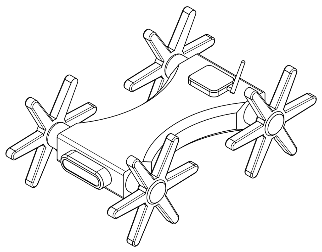
The locomotion system is a critical component of any robot as it enables it to travel to the location where it will carry out inspection or operation tasks. Consequently, numerous researchers have devoted their efforts to creating locomotion systems that enhance the mobility of robots in challenging terrains. In terrestrial settings, two of the most common locomotion methods available are based on wheels and legs, as shown in
Figure 1.
When it comes to flat surfaces, a locomotion system with wheels is the most suitable option. The efficiency of this system is considerably superior to that of legged locomotion when traveling across even terrain [
1]. On the contrary, legged locomotion systems are known for their superior maneuverability in unstructured environments.
In recent years, some researchers have proposed designs of hybrid locomotion systems based on wheels and legs [
2]. In this work, the height of the stairs is related to the height of the robot, classified as low, medium, and high. These proposals can be classified as robots with wheels and legs, transformable wheels/legs, wheeled legs, and legged wheels.
Robots can use different strategies to climb obstacles using wheels and legs in alternation. Legs are employed when the wheels are not able to cross an obstacle. A different design concept corresponds to wheels that can be transformed into legs [
3,
4]. Tadakuma et al. [
3] presented the design of a transformable wheel composed of a three -degrees-of-freedom serial mechanism. On the other hand, in [
4], Lin and Shen introduced the design of a wheel that transforms into a C-shaped leg. Another approach to the design of the locomotion system involves attaching wheels to the ends of mechanical limbs. These limbs can be activated [
5], under-actuated [
6], or passive. By doing so, the position of the wheels around the robot’s center of mass can be altered, enabling the robot to overcome obstacles and maintain its stability.
Some researchers have implemented legged wheels in mobile robots. A legged wheel is a symmetrical body with multiple limbs that are rotated by an actuator; this concept was initially proposed in [
7,
8]. In [
9], Eich et al. presented the Asguard mobile robot. The robot has four actuated-legged wheels with five limbs with a flexible tip. The robot has an additional rotational degree of freedom along the body axis, serving as an elastic spinal column. This robot is capable of climbing stairs, traversing very rough terrain, and moving quickly on flat ground.
On the other hand, some designs of legged wheels that can change their shape have been proposed [
10]. In this document, we will refer to these devices as
variable geometry legged wheels (VGLWs). In [
11], Moreno et al. introduced the Heise wheels, a series of two-degrees-of-freedom mechanisms that are capable of transforming a circular wheel into a legged wheel. A linear actuator extends/flexes the limbs of the wheels, and this permits adjustments to the geometry of the wheel according to the terrain it is traversing. In the literature, different designs of VGLWs can be found. There are one- [
10], two- [
12,
13,
14,
15,
16,
17], and three- [
18] degrees-of-freedom VGLWs. Most of the designs employ electric actuators, but some proposals use pneumatic [
19] and hydraulic actuation [
20]. The designs of underactuated VGLWs are described in [
21,
22].
There is a wide variety of applications for mobile robots, including assistance in household activities, surveillance and security, healthcare and rehabilitation, agriculture, and space exploration. Legged wheels and VGLWs can be useful in overcoming steps or stairs in structured environments or traversing difficult, unstructured terrains or stairs. Different robots have been used for stair climbing, relating some parameters to the design. The HyTRo-I robot deploys retractable leg mechanisms to climb stairs when the height of the step is greater than the radius of the wheel [
23]. The robot, named LZ-1, uses a wheel mechanism based on a mecanum wheel [
24]. One of its most important design parameters is the consecutive angles between the legs; in this case, only the height, h, of the stair is related. On the other hand, the 4r+2P robot uses a crank mechanism to place a fixed part on the stairs and then raise its two wheels [
25]. In order to perform this operation, they calculated the angle that indicates the position of the crank in relation to the wheels and related the height, h, and friction coefficient. The minimalist robot is based on the connection of three links, with two wheels at the beginning and end of the scientific chain to lift the stairs [
26]. The design parameters that relate to the steps are the height of the step and the distance between the centers when placing the wheels at the corners of the steps. The track wheel robot has four active pulleys and four slave pulleys, with which it can form a three-link kinematic chain [
27]. These links are synchronized to allow it to pass over the steps. The design parameter used is the height of the step. Finally, we observed the implementation of an anti-skid mechanism in a conventional wheel to climb the stairs [
28]. The primary aim of this study is to formulate a design theory that relies on the geometric parameters of legged wheels to facilitate the efficient climbing of stairs by robots.
This paper presents a comprehensive study on the effect of the geometry of the legged wheels on the performance of a mobile robot in the stair climbing task. As main parameters, we consider the number of legs, the diameter of the wheels, and the distance between the wheels. In this paper, we have different sections, starting with the method section. This section explains the interaction and the steps to determine the parameters that influence the design of these structures. The results section presents the statistical analysis showing how many times the geometric configuration of the structure was able to overcome obstacles. The implementation section provides a case study aimed at validating the steps of the proposed design theory. Finally, the conclusion section summarizes the work carried out in this article and its relevance to the field of robotics.
2. Methods
Since it is necessary to determine the parameters that have the greatest impact on the design of these robotic structures, a series of dynamic simulations in solidworks is proposed. The main hypothesis to be tested is if the dimensionless quotient
of the wheel opening
and the diagonal
of the stair step has a direct relationship with the robot’s progress on the proposed task, as in (
1), shown in
Figure 2. The independent variables were
, the number of legs of the wheel;
, the distance (cm) between the center of the wheels;
, the radius of the wheel (cm), and
, the height (cm) of the steps, and the dependent variable was whether the robot could climb and descend stairs. For these simulations,
is the width (cm) of the steps,
w is the angular velocity (rpm),
is the static friction coefficient, and
is the dynamic friction coefficient, and these were taken as constants, where
(cm) can be calculated by (
2).
When performing the simulations, the robot is on the ground, so the effect of gravity allows it to have contact with the ground while the wheels rotate at a given speed. The robot moves towards the stairs, which it tries to climb using the extremities as support points. The robot structure is flat, so this structure also has contact with the stairs. Finally, the structures that manage to go up the stairs must go downstairs with the same dimensions as the climbing ones. The parameters of the simulations are shown in
Table 1.
2.1. Simulation
By using
Table 1, 63 simulations were performed, in which the scenarios were varied to see the behavior of the robot when trying to climb the stairs. These 63 simulations are the combinations of varying the wheels from 3 to 10 legs, with eight different radii of wheels to climb two types of stairs with different dimensions.
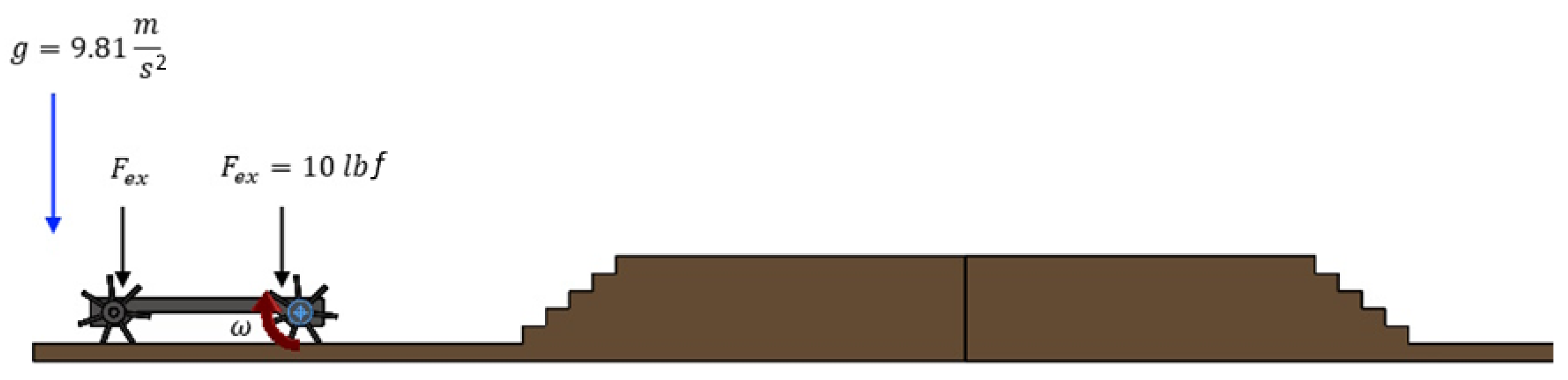
Figure 3 is an example of the simulations performed, applying gravity to the robot structure. The angular velocity of the robot motors was varied from
= 15 rpm and ended the simulation with
= 10 rpm. These angular velocities, according to different authors, show some variations, with [
29] using 6.667 rpm, whereas [
30,
31] used 15 rpm, and [
32] used 16.5 rpm. Two external forces,
(20 lbf) are applied to the ends of the structure due to the design of it, which is hollow in the center. Variations in the weight that such a structure can carry range from 1.6 lbf to 20 lbf [
33].
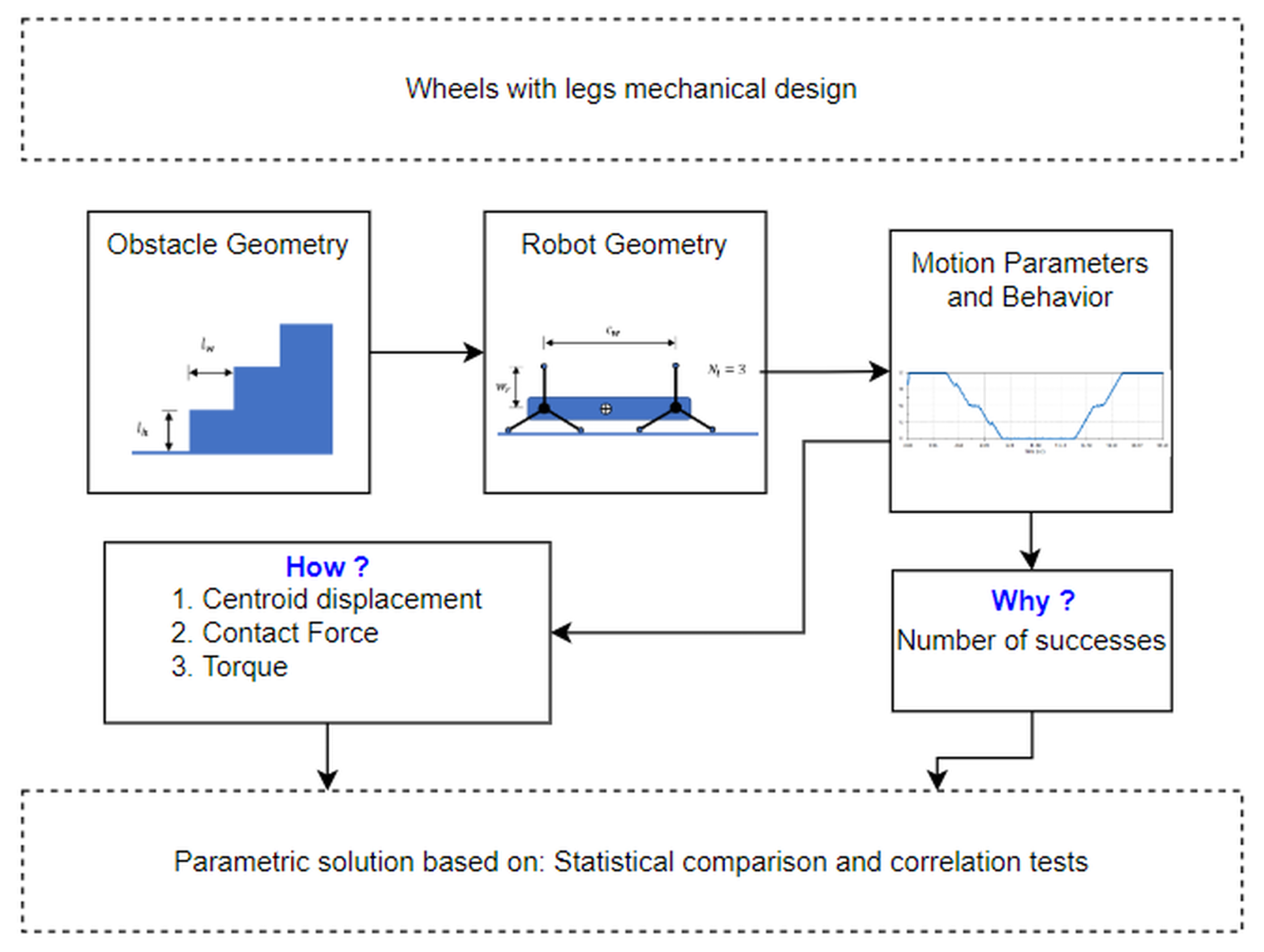
In order to verify if this ratio has normal behavior, a Shapiro–Wilk test was performed on all the calculated coefficients grouped by their
. Subsequently, the results of how the robot manages to perform the test, the torque of the motors, and the contact force were analyzed. For this, the successful coefficients were categorized to find the ranges in which the probability of success of the robot is higher. The complete method of this research can be seen in
Figure 4. At the end of the statistical analysis, an additional simulation is carried out to calculate the dimensions of the wheel legs based on (
2) for a stair with dimensions different from those already carried out.
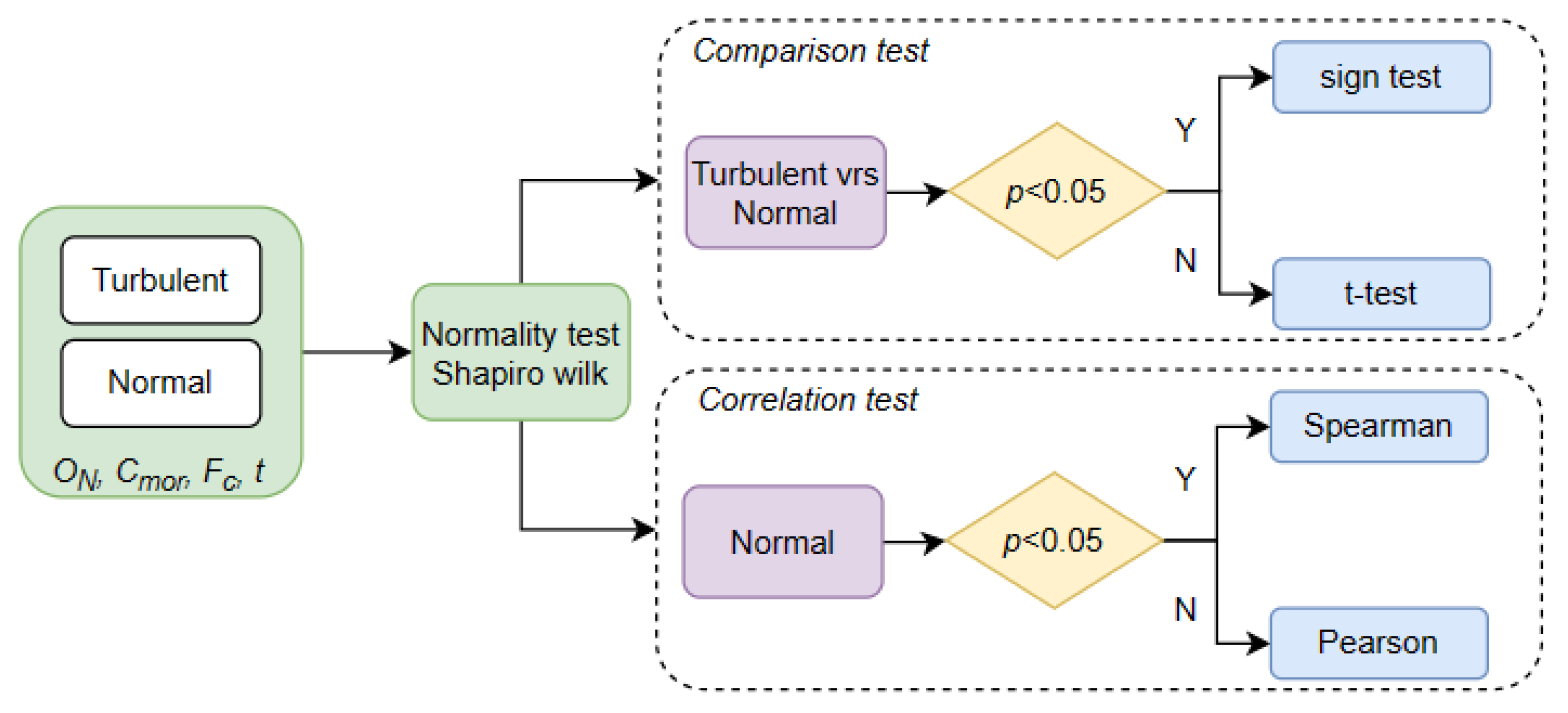
2.2. Why Did the Robot Succeed?
The first question of this research is, why do some wheel configurations manage to climb stairs and others do not? The ratio of the opening of the extremities and the diagonal of the stairs were calculated to check if this indicator is determinant in the design of these robotic structures. For this purpose, the configurations of wheels and structures that climb the stairs were separated from those that do not, performing statistical tests to demonstrate that they have significant differences. Subsequently, the confidence interval where the indicator has a higher probability of success is determined.
The two parameters to analyze are
and
, which demonstrate that these parameters affect the success of the robotic structure in solving the problem. The use of statistical tests was proposed, as shown in
Figure 5.
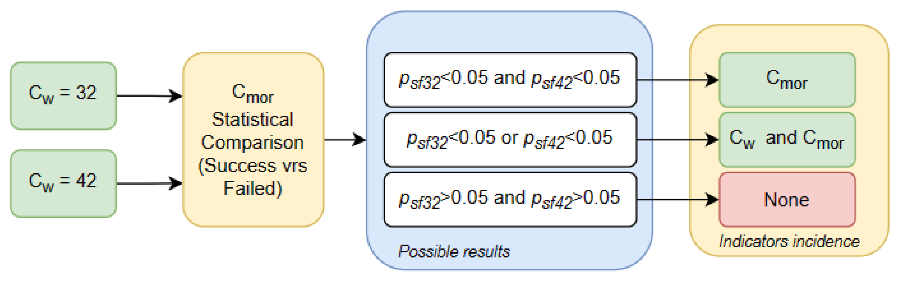
For the
, the total number of tests was divided according to its
and according to the success or failure in performing the test. Subsequently, a normality test was applied according to its
to determine the type of statistical comparison test to be performed. If the statistical comparison test obtained a value
, it means that there was a significant difference between the value,
, of the successes and failures.
Figure 6 allowed us to determine the incidence of the indicators in the design of these structures.
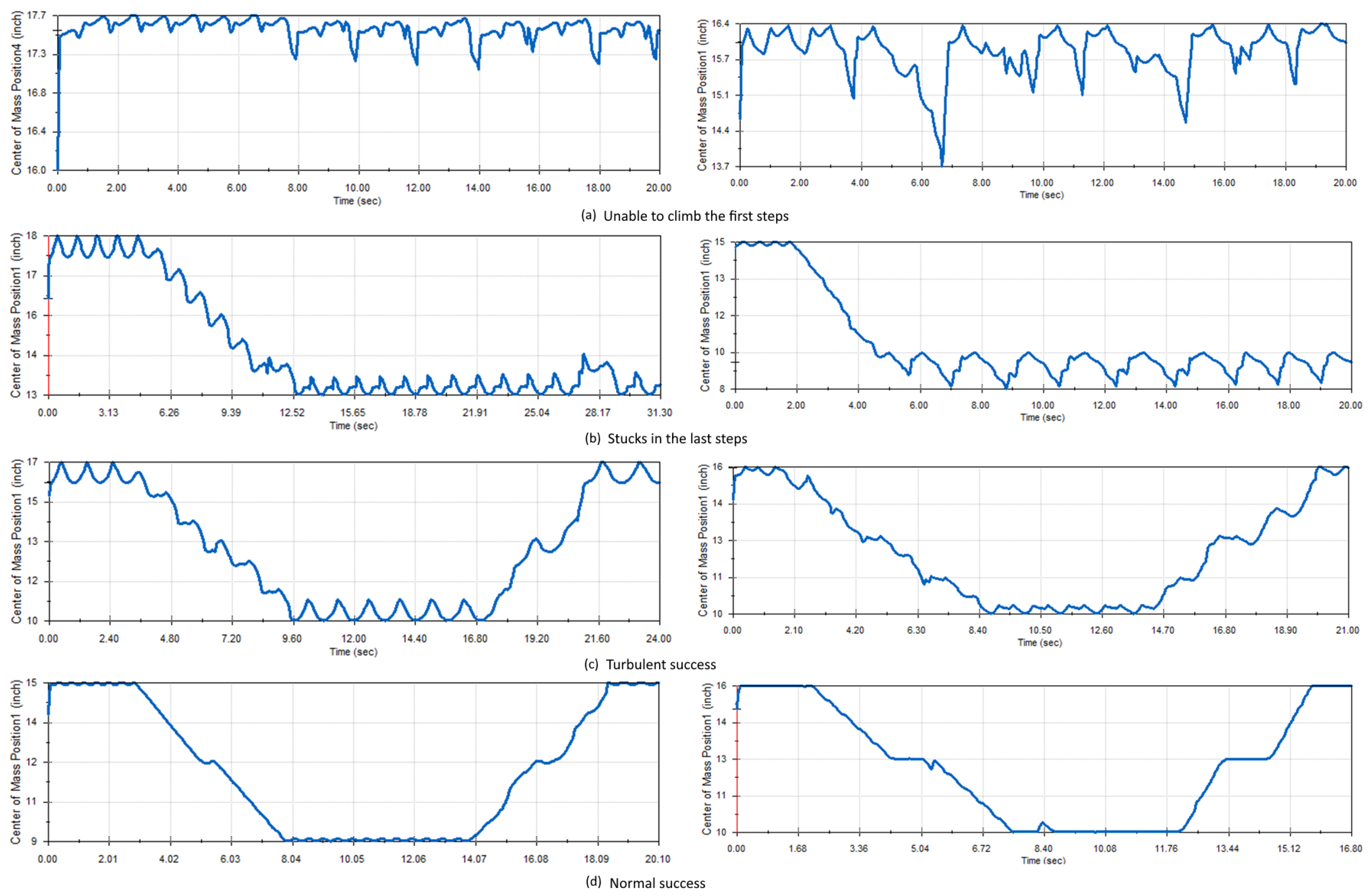
2.3. How Does the Robot Succeed?
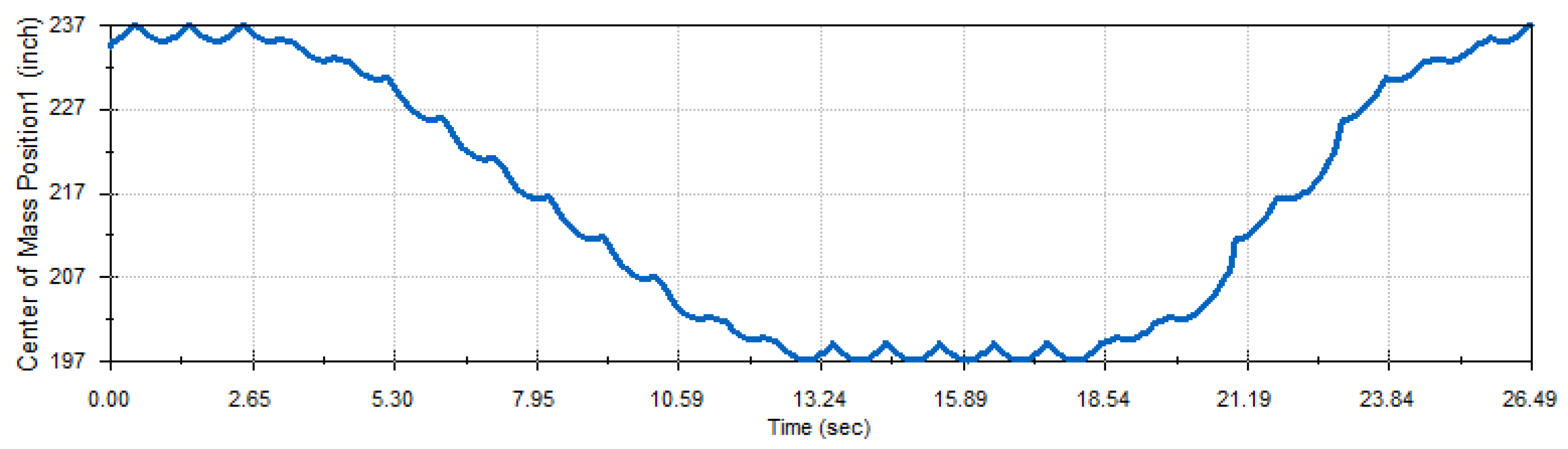
The second question of this research tries to help describe graphically and statistically how the robots climb. On many occasions, the robot can solve the problem of climbing the stairs, but it generates contact forces that can damage the structure, very high torques that can overload the motors, or constant vibrations that can reduce the life of the equipment. Therefore, the simulations will be graphically classified based on the behavior of the center of gravity of the structure. This will be classified into four groups: the first and second groups are the structures that did not manage to climb, the third group represents the structures that climb but without stabilizing their center of mass (turbulent), and the fourth group represents the structures that climb by stabilizing their center of mass (normal). Statistical tests were then performed to compare whether the indicators shown in
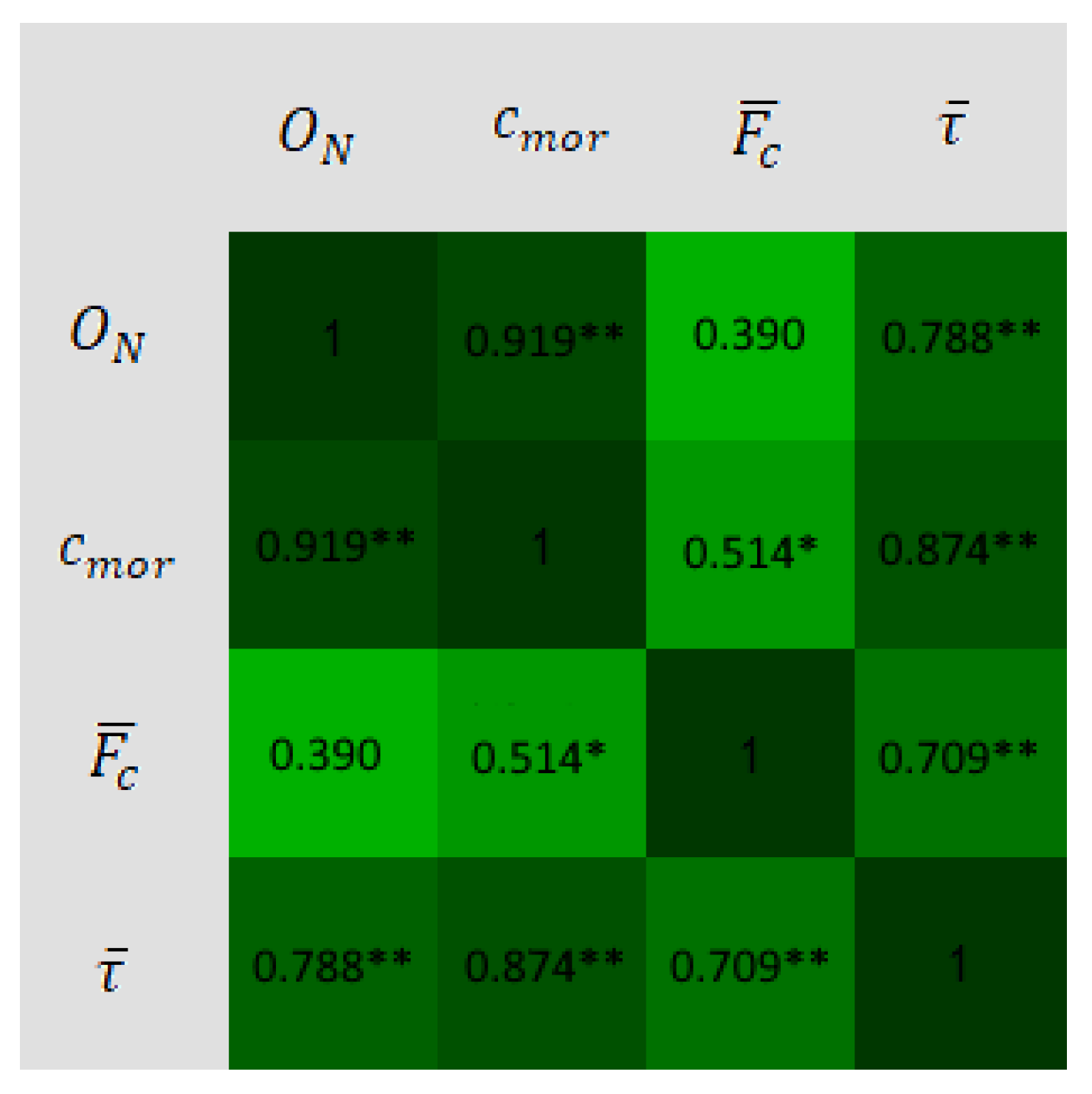
Figure 7 had different behavior. Finally, a correlation test was performed to determine how much
affects the design.
5. Discussion
Although numerous authors have previously presented diverse analyses and methodologies for the design of hybrid wheels, it should be noted that many of these works predefine the various geometric attributes of the wheels, notably the number of legs [
7,
9,
12,
22,
32,
34,
35,
36,
37]. In contrast to these prior approaches, our research takes a problem-centric approach, establishing a fundamental link between the harrow’s dimensions and the wheel opening as its foundational premise. In order to identify the appropriate design parameters, we conducted a statistical analysis, varying the number of legs through simulations. To our knowledge, there is only one study that uses a similar approach: using statistics to determine wheel efficiency and the optimal number of legs by taking step height as a parameter [
38]. In our work, the number of legs is determined in accordance with the step’s height and also considers the spacing between the wheel centers in the robot design. This aligns with what previous authors suggest, with a key distinction being that our method allows the designer to select the number of legs, as there is no single solution. The critical element in our approach is the introduced metric,
, which relates the step’s height and width by considering its diagonal and the wheel’s opening. This method is shown in the application section, where the procedure for dimensioning the wheels and the distance between the centers is exemplified. Notably, a major difference from prior work, like [
38], is that, as legs are added, the radius of the wheel decreases. In contrast, our proposed method exhibits an inverse relationship; as the number of legs increases, the radius of the wheel also increases. Therefore, the main contributions of this work are as follows:
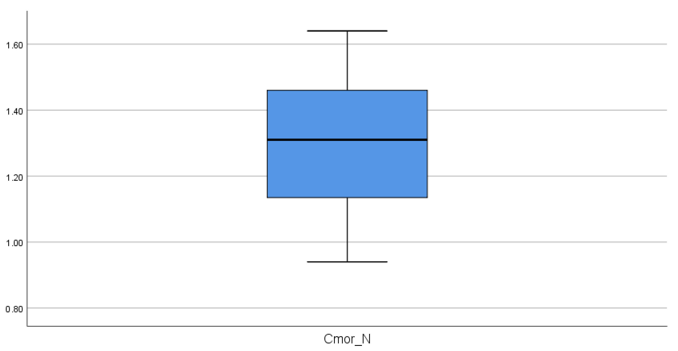
The proposed indicator was determined to relate the harrow dimensions to the opening of the wheel legs. This adimentional parameter showed the highest efficiency for overcoming the stairs at a value of 1.3; it also showed a strong correlation with motor torque and a weak correlation with contact force.
The development of a method for designing wheels with legs based on the center distance parameter and the indicator .
6. Conclusions
The development of this work showed several of the problems that robotic structures must overcome to climb sets of stairs. First, it was shown that the opening of the legs of the wheels is a geometric parameter that determines whether the structure will be able to climb the stairs. The second problem is when the robot becomes stuck, which occurs at the beginning of the step or at some point during the climb of the structure. In order to solve these problems, 63 simulations were performed whereby the wheel opening, , the wheel radius, , and the distance between the centers of the front and rear wheels, , were varied. The statistical tests showed significant differences between the geometric parameters that succeeded and those that did not. Furthermore, strong correlations were obtained between and motor torque, and at a lower level, with contact force. Therefore, it is concluded that the proposed indicator , and the center-to-center distance, , are the geometric parameters with the greatest impact when constructing these structures. A design methodology based on the geometry of the wheel is proposed using and the geometry of the structure . This methodology was validated with an additional simulation that was performed with a four-legged wheel. In future work, we propose the fabrication of robots by applying this methodology, where the main limitation found is the dimensions of the wheels.


 ,
, 


