Article

Analysis of High-Speed Rotor Vibration Failure Due to Sudden Angular Deformation of Bolt Joints

1
School of Energy and Power Engineering, Beihang University, Beijing 102206, China
2
Shenyang Engine Design and Research Institute, Aero Engine Corporation of China, Shenyang 110015, China
3
Research Institute of Aero-Engine, Beihang University, Beijing 102206, China
*
Author to whom correspondence should be addressed.
Symmetry 2023, 15(10), 1937; https://doi.org/10.3390/sym15101937
Submission received: 21 September 2023 / Revised: 12 October 2023 / Accepted: 16 October 2023 / Published: 19 October 2023
(This article belongs to the Special Issue Symmetry in Mechanical Engineering: Properties and Applications)

Abstract

:
As the efficiency of advanced aero engines improves, the operational speed of their rotors increases. This heightened operational speed makes the rotor dynamics highly sensitive to changes in the rotor’s mass asymmetry state, or unbalance state. During the use of a dual-spool turbofan engine, when its supercritical high-pressure rotor (HPR) exceeds a certain operational speed, the rotor’s vibration spikes and continues to increase with the operational speed until it drops sharply near the maximum operational speed. Analysis of the bolt joints in the faulty rotor reveals various phenomena such as joint interface damage, changes in bolt loosening torque distribution, and alterations in rotor initial unbalance. This paper proposes that at high operational speeds, the bolt joint of the HPR undergoes sudden angular deformation, resulting in the slanting of the principal axis of inertia of the turbine disk. This slant leads to changes in the unbalanced state of the HPR. The additional unbalance causes a sudden rotational inertia load excitation, triggering the rotor vibration failure. Subsequently, a rotor dynamic model that incorporates the angular deformation of the joints is established to simulate how this joint deformation influences the dynamic response of the rotor. The simulation results align well with the observed failure phenomenon and validate the proposed failure mechanism. Finally, troubleshooting measures are proposed and implemented in the faulty engine, effectively mitigating the vibration fault.

1. Introduction

As advanced aero engines develop toward high performance and structural efficiency, their structural systems have become more complex. A rotor with a poor unbalance state can exert excessive rotational inertia load during high-speed rotation, resulting in rotor vibration failure.
Existing rotor dynamic models, such as the Jeffcott model [1] or the four-degree-of-freedom (DOF) rotor model [2,3,4,5], often equate the rotor’s unbalance state to the center of mass (CM) offsets on one or more rotor cross sections and simplify the rotational inertia load to a lateral harmonic excitation force in these CM offset planes. According to this assumption, research has been conducted on rotor dynamics [6,7,8]. In these rotor dynamic models, when the operational speed of a CM-offset rotor exceeds its first and second critical speeds, the rotational inertia force caused by the CM offset will decrease as the operational speed increases owing to the inward turn of the CM. Therefore, when the operational speed of a supercritical rotor is largely far away from its critical speed, the CM offset is unlikely to cause an excessive dynamic response. However, for a thin disk (i.e., disks with a ratio of polar moment of inertia Ip to diameter moment of inertia Id greater than 1) with a slanted principal axis of inertia (PAI), its rotational inertia load can increase with operational speed under supercritical conditions [9,10] and cause rotor dynamic response to increase continuously, which has been found in several rotor vibration failures [11,12,13]. Therefore, considering the influence of disk slant in the dynamic response analysis of a supercritical rotor is critical.
Several studies have also delved into the impact of the mechanical characteristics of joints on rotor dynamics. Qin [14,15] and Luan [16] modeled the bending stiffness of the rotor’s joints as a function of operational loads, examining its influence on rotor dynamics. Zhuo [17] and Chen [18,19] discovered that bending moments can induce non-axisymmetric changes in the contact stress distribution at the joint interface, leading to reductions in joint bending stiffness and bending mode frequency. Beyond the stiffness considerations, the deformation of these joints has also been a point of focus. Yu [20] explored the bolt flange’s deformation under bending moments, suggesting that micro-slips between interfaces can introduce damping nonlinearity in the rotor, potentially leading to self-excited vibrations in the rotor system under supercritical conditions. Shi [21] and Jaszak [22] studied the macro deformation of the flange-bolt joints in pipes under axial force and bending moment, highlighting that increasing bending moments can induce an abrupt angular deformation due to macro slips at the interface. In an experimental investigation, Hong [23] subjected a bolt-jointed rotor to repeated bending, concluding that such joint deformations can degrade the rotor’s dynamic response. Liu [24] also pinpointed the detrimental effects of bolt joint deformations on rotor dynamic response, which originate from interfacial cutting faults. Neither of the two investigations adequately addressed the root causes of these abnormal experimental observations. To elucidate how the deformations of rotor joints impact rotor dynamic response, Sun [25] and Chen [26] developed rotor unbalance models considering joint deformation. They observed that joint deformation can change the rotor’s unbalanced state, subsequently affecting its dynamic response. Yet, they equated the influence of joint deformation on rotor unbalance with an added CM offset, but this equation cannot explain the supercritical rotor’s dynamic response. Therefore, understanding rotor joint deformation and its negative implications for the thin disk’s PAI slant is essential to unveiling the mechanistic progression of how joint deformation influences the rotor’s supercritical dynamic response.
In summary, this paper analyzes the failure of a turbofan engine. A rotor dynamic model that accounts for abrupt angular deformation of the joint and its impact on the disk’s PAI slant is established. The simulation of rotor dynamic response is carried out to reveal the failure process. Finally, corresponding vibration troubleshooting measures are proposed, and their effectiveness is verified in another engine test.

2. Phenomenon of Vibration Failure

Figure 1a shows a dual-spool low-bypass-ratio turbofan engine. To monitor the engine’s vibration, accelerometers are arranged at the engine’s intermediate frame and rear turbine frame (points A and B in the figure). The operational speed of the high-pressure rotor (HPR) of the engine is relatively high, far exceeding the first/second critical speed. However, owing to the high bending stiffness of the rotor, its operational speed is much lower than the third critical speed. Therefore, at its maximum operational speed, the rotor will not undergo modal vibration, and its dynamic response amplitude depends on rotor unbalance.
The HPR consists of multiple components that are connected by bolt joints. The deformation of the joints during operation can affect the rotor’s unbalance and dynamic response, particularly for bolt joints located before the turbine, which operates in a high-temperature environment with high linear velocity and significant axial force. As shown in Figure 1b, the bolt joint before the turbine connects the rear flange of the drum shaft, the labyrinth disk, and the front flange of the turbine disk. During operation, the different geometries and operational loads of these components can cause them to experience varying radial deformations. This can negatively impact the contact characteristics of the joint interfaces, leading to interfacial slippage and joint deformation.
During usage in real scenarios, the engine mounted on aircraft underwent severe vibrations that exceeded the allowable limit. Following the failure, an analysis of the vibration signals achieved by the accelerometer at Point A and a comprehensive inspection of the faulty HPR were conducted.

2.1. Signal Analysis of Engine Vibration

As shown in Figure 2a, the engine’s vibration amplitude changes with the operational speed of its HPR and low-pressure rotor. When the HPR’s operational speed is increased to 16,000 RPM (~75% of its maximum operational speed and significantly exceeding its first and second critical speeds), the engine’s vibration suddenly increases (S.I.) with minor changes in operational speed. As the operational speed continues to increase, the vibration rapidly rises, which can be described as vibration following (V.F.). When the HPR’s operational speed reaches ~21,000 RPM (close to its maximum operational speed), the vibration suddenly decreases (S.D.). At this point, the engine’s vibration reaches 80–90 mm/s, far exceeding the limit. It is important to emphasize that the operational speed of the HPR was deliberately varied, oscillating at different rates. As depicted in the figure, once the operational speed of the HPR remains at 16,000 RPM for several seconds, S.I. occurs; once the speed escalates to 21,000 RPM, S.D. occurs. Consequently, the repeatability of this unusual experimental phenomenon can be validated.
Taking time interval T in Figure 2a as an example, Figure 2b shows the frequency composition of the engine vibration. The energy of the vibration is primarily attributed to the rotation of the HPR (as indicated by N2 in the figure), with virtually no other frequency components present. This suggests that the sudden increase in vibration is attributable to a sudden change in the HPR’s unbalance.
However, the HPRs of aeroengines typically operate well below the critical speed of bending modes. As a result, they are often characterized as rotors exhibiting rigid behavior [27]. In engineering analyses, the 4-DOF rotor dynamic model, excited by CM offset, is frequently employed to describe their dynamics. Based on this 4-DOF rotor dynamic model, when the rotor’s operational speed surpasses both the first and second critical speeds, the rotor’s dynamic response, which is generated by the excitation of CM offset, will decrease with an increase in operational speed. This is due to the inward turn of the rotor’s CM, regardless of the magnitude of this CM offset. This differs significantly from the observed experimental phenomenon, where the vibration of the rotor increased rapidly with operational speed.
For time interval T, the 1× RPM vibration of the HPR at points A and B is extracted, and Figure 3 shows the changes in the vibration phase of these two points over time. According to this figure, the whirling phase of the HPR’s front and rear bearings changes when there is a sudden change in engine vibration. This phenomenon also significantly differs from the whirling phase change caused by the inward turn of the CM. When a 4-DOF rotor with a CM offset passes through its first and second critical speeds, the change in the whirling phase of its front/rear bearing should be 0° or 180°. However, during this engine vibration failure, throughout the S.I. and S.D., the changes in the whirling phase of the front bearing are 170° and 210°, respectively, while those of the rear bearing are 120° and 150°. Therefore, this phenomenon cannot be explained by the traditional 4-DOF rotor dynamics model excited by the CM offset.

2.2. Interface Damage and Deformation of Rotor Joints

During the thorough inspection of the faulty engine, all components were found to be within acceptable limits as specified by the maintenance manual, except for the unusual deformation and the interfacial damage of the bolt joints in the HPR.

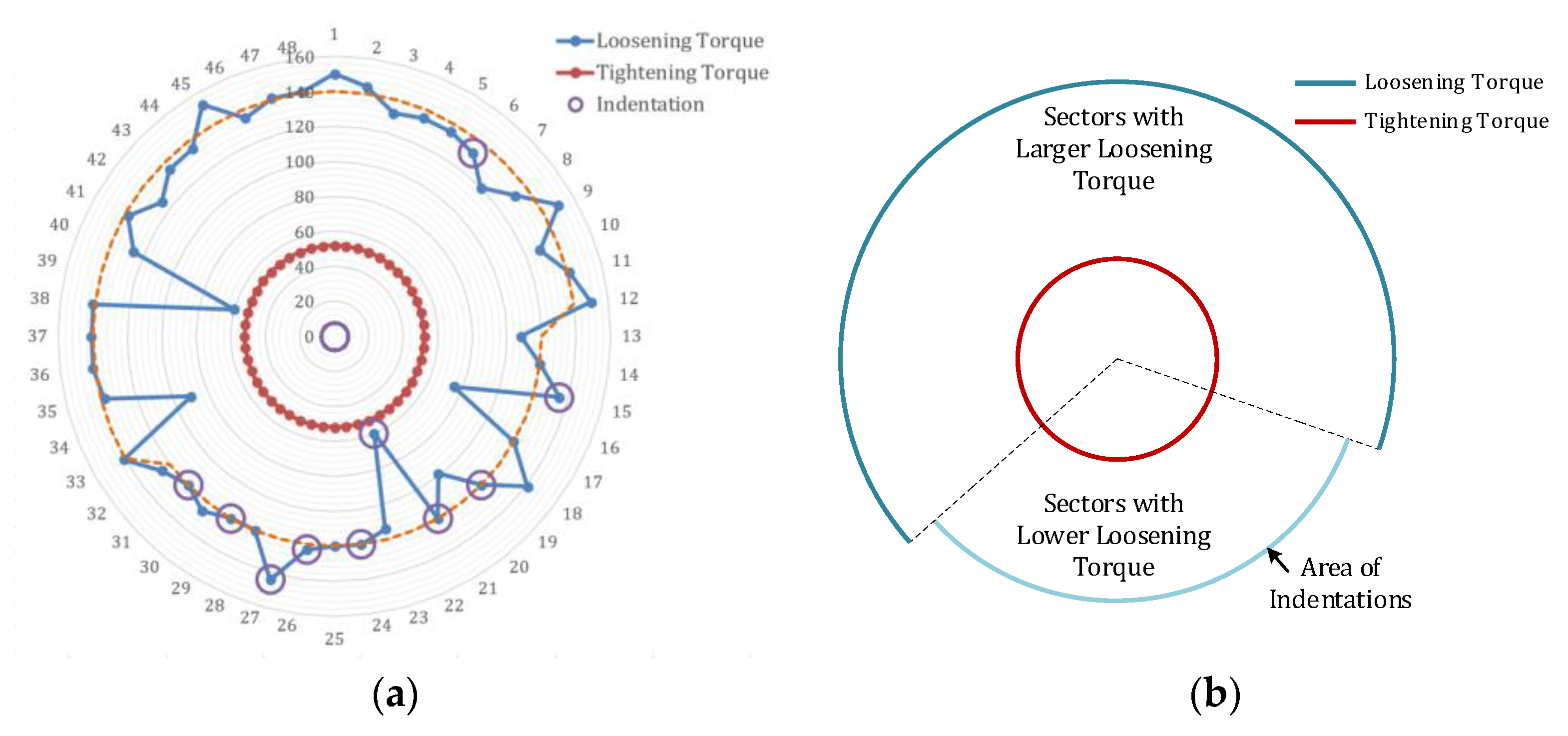
2.2.1. Loosening Torque Distribution of Bolt Joints

Owing to the irreversible slip of joint interfaces under operational loads, the pre-strain of the bolts changes relative to their initial state. Consequently, a significant difference can exist between the loosening torque and the tightening torque of the bolts [28]. The interfacial-slip-induced deformation of joints can be evaluated by measuring the loosening torque of the bolts and analyzing their distribution during rotor disassembly.
Figure 4 shows the distribution of loosening torque in the HPR joints. All loosening torques show a significant increase (>200%), indicating that the joint interfaces experience irreversible slip owing to the harsh operational load. However, a comparison of the joints reveals that the loosening torques of the bolt joints before and after the turbine are distributed in a “spindle shape”. This indicates that the two joints were subjected to a large bending moment during operation and underwent angular deformation, resulting in a systematic orientation of deformation in their bolts [22,28].

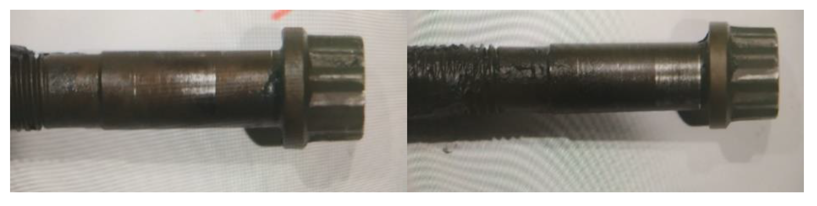
2.2.2. Interface Damage of Bolt Joint End Faces

As depicted in Figure 5, triangular marks are present on the turbine disk’s front-end face, distributed outside the bolt hole. Microscopic inspection and surface topography scanning reveal that these marks are protrusions of material from the substrate surface, and they are referred to as “stains” in this paper. Physicochemical analysis of the stain compositions (Table 1) indicates that they are identical to the composition of the substrate materials, except for the presence of molybdenum. Considering the location of the stains, the most likely source of the additional molybdenum is the bolt lubrication containing MoS2. It can be inferred that during operation, the end faces of the bolt joint did not make proper contact with each other, allowing some lubrication to leak into the gap between the end faces and corrode the surface. Owing to the high temperatures, the corroded surface experienced material growth, resulting in the formation of stains.
Considering that the size of the gap between the end faces determines the amount of lubrication leakage, the poorer the contact between the end faces, the thicker and larger the stains. The distribution of the stain thickness along the circumferential direction (Figure 6) indicates that the gap in the joint’s top half is larger than that in the lower half, and the joint underwent angular deformation during operation. Furthermore, as the gap between the end faces can cause the bolt to stretch and increase the preload of the bolt, the sectors with larger bolt loosening torque are also located in the top half of this bolt joint, overlapping with severely stained sectors (Figure 4). This further confirms that angular deformation occurred in this joint during the operation.

2.2.3. Indentations on Bolt Screws

In addition to damage on the end face, some indentations also occur on the surface of the screws of the bolt joint before the turbine (Figure 7). These indentations result from the extrusion of the bolt hole on the screw due to uncoordinated radial deformation between the labyrinth disk and the turbine disk under centrifugal force and thermal deformation. Analysis of the position of these indentations and their correlation with the bolt’s loosening torque reveals a typical distribution pattern, which is illustrated in Figure 8. This figure shows that the abnormally indentated screws are relatively concentrated, with most of them found in sectors with relatively small loosening torque. This is related to the lower frictional constraint in sectors with smaller loosening torque, which cannot effectively restrain the relative displacement between the end faces, resulting in the squeezing of the screw by the screw hole.
The phenomenon of joint deformation and interface damage resulting from the combined action of centrifugal force, thermal deformation, and axial force reveals that the contact between the components of the bolt joint before the turbine is not effective, leading to irreversible interfacial slip. Consequently, changes in bolt loosening torque, end face damage, and indentations on the screw surfaces occur. These changes are unevenly distributed across the circumference of the bolt joint. This suggests that the bolt joint before the turbine is subjected to a large bending moment during operation and experiences angular deformation.

2.3. Change in Rotor Unbalance

Table 2 presents the changes in the HPR’s unbalanced state before and after engine usage. It is important to emphasize that, when measuring its unbalance, the rotor lacks blades and balancing mass. Consequently, the measured rotor unbalance stems exclusively from the rotor’s asymmetrical deformation. The unbalanced state of the compressor module undergoes relatively minor changes before and after the test. However, the unbalance state of the turbine module experiences significant changes in its front balance plane (B.P.), with the amplitude of unbalance increasing from 540 to 1190 g/mm and the phase of unbalance shifting from 343° to 210°. Additionally, a substantial change in unbalance exists in the rear B.P. of the HPR, with the phase of unbalance changing from 23° to 330°. These changes align with the unbalanced changes in the turbine module.
Considering the circumferential nonuniform distribution of bolt loosening torque, interface damage, screw indentation, and changes in HPR distribution, it can be concluded that during HPR operation, the harsh environment leads to interfacial slip and angular deformation of the bolt joint before the turbine. This, in turn, results in a change in the unbalance of the turbine module by slanting the thin turbine disk. The slant of the turbine disk generates significant rotational inertia moment excitation in the rotor’s supercritical state, which likely contributes to the vibration failure of the HPR.

3. Dynamic Analysis of the Jointed High-Speed Rotor System

Analysis of the failure phenomena reveals that the angular deformation of the bolt joint triggers the vibration failure of the HPR by altering the rotor’s unbalance. In this section, a rotor dynamics model that considers the sudden angular deformation of the joints is established. Through simulation of sudden changes in rotor dynamics, the mechanism underlying the rotor vibration failure is revealed.

3.1. Joint Interfacial Slip and Angular Deformation

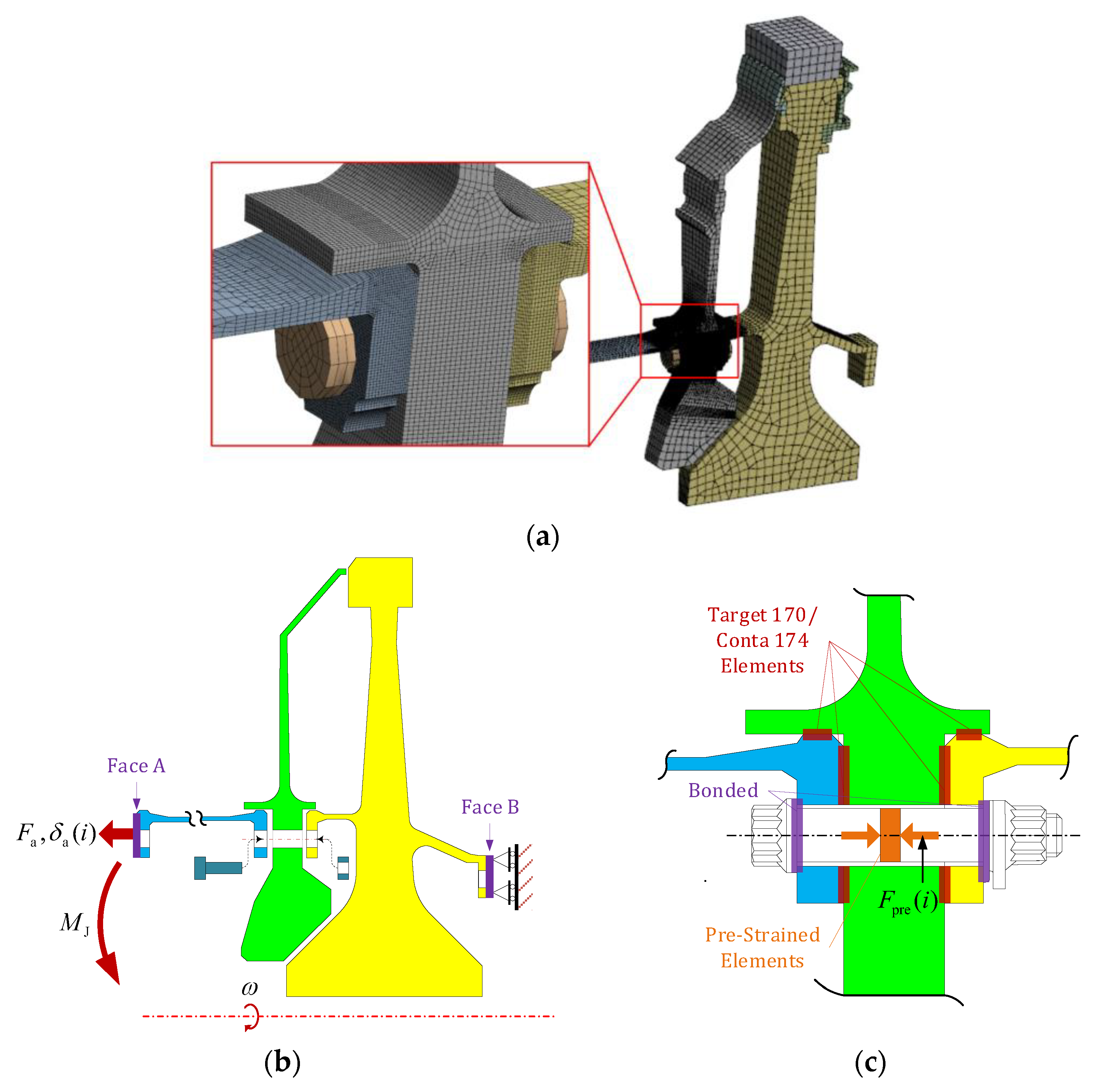
3.1.1. Bolt Joint Deformation Model

Figure 9 shows the operational loads applied to the bolt joint before the turbine disk. In its initial state, owing to the axial compression of the bolt and the interference fit of the centering faces, the flange is subjected to axial compression force from the bolt F P , contact stress from the end face P E ( y ) , and contact stress from the centering face P R ( x ) .
When an operational load is applied to the joint, under the action of axial force F a , centrifugal force, and thermal load, the joint’s centering face undergoes axial relative sliding. The direction of deformation δ a and the direction of frictional force F f on the flange’s centering face are shown in this figure. The axial deformation of the flange causes axial deformation of the bolt, increasing residual preload inside the screw. Additionally, under the action of external loads, interfacial contact stress distribution P E ( y ) and P R ( x ) will also change. According to force balancing,
F a + F c = F f + k θ δ a + F P ,
where k θ is the axial stiffness of the flange, F c is the reaction force applied to the end face, F f is the frictional force applied to the centering face, and can be expressed as
F c = P E ( y ) d y , F f = μ P R ( x ) d x .
From Equation (2), the axial slip of the centering face under operational force δ a can be obtained. This slip depends on the axial force F a , the residual preload of the bolt F P , and the contact stress distribution of the centering face P R ( x ) .
As shown in Figure 10, when the joint is subjected to a bending moment load M J , its upper sectors experience tension while its lower sectors undergo compression. This indicates that the operational load applied to the joint is non-axisymmetric. Consequently, the interfacial slip and axial deformation of each sector can vary, resulting in the angular deformation of the joint. Similarly, owing to variations in bolt preload and the contact status of the centering faces, the interfacial constraint of the joint also exhibits a non-axisymmetric characteristic, which can contribute to angular deformation of the bolt joint [29]. Additionally, considering that interfacial slip often occurs abruptly when the applied load surpasses a certain threshold, changes in the joint’s angular deformation can also exhibit a sudden characteristic.

3.1.2. Simulation on Bolt Joint Angular Deformation

A simulation model of the bolt joint before the turbine disk is established to simulate the angular deformation of the joint (Figure 11). Both the FEM modeling, the boundary condition setup, and the solving of this model are realized in the commercial FEM software ANSYS 2021. Two sets of simulations are conducted to investigate the mechanism through which the unevenness of the bolt preload and moment load affects the deformation of the bolt joint. In Set A, let ω , F a , and F pre ( i ) satisfy the relationship as
ω / ω max = F a / F a , max = β ,
F pre ( i ) / F pre , max = 1 + 2 i 2 N / N 1 γ .
Equation (3) indicates that the rotor’s operational speed and the axial force applied to the bolt joint will increase linearly. Equation (4) indicates that bolt preload varies linearly with its circumferential position, where γ is a factor that determines the difference between the maximum and minimum preloads of the bolts, and γ can be expressed as
γ = F pre , max F pre , min F pre , max .
Figure 12 and Figure 13 show the FEM simulation results of the joint’s angular deformation. In Figure 12, when the operational speed reaches 72% ω max , the top half of the bolts, characterized by lower preload, experience larger axial deformation, resulting in an abrupt angular deformation of the joint (~ 10 4   rad ). In Figure 13, when M J is low and no macroscopic slip occurs on the centering face, the angular deformation of the bolt joint is relatively small. However, once M J exceeds a certain threshold, the joint also undergoes sudden angular deformation (~ 10 4   rad ) owing to the slip of the upper bolt sectors.
According to these simulation results, both the non-axisymmetric bolt preloads and the bending moment can induce a sudden angular deformation of the bolt joint before the turbine disk. This angular deformation of the joint can result in a change in the PAI slant of the turbine disk, resulting in a significant rotational inertia moment excitation at high operational speeds, thereby affecting the rotor’s dynamic response.

3.2. Rotor Dynamic Analysis Considering Joint Angular Deformation

3.2.1. Rotor Dynamic Model with Distributed Rotational Inertia Load Excitation

As shown in Figure 14a, when the HPR undergoes bending deformation while rotating, the relative position relationship between its components changes, particularly in terms of the angular relative position. Each component exhibits a different whirling state owing to variations in materials and geometric configurations. Consequently, the influence of the components on rotor dynamics, including rotational inertia load excitation and gyro-effect, also varies. At this stage, considering the rotor as a whole is no longer appropriate, and it becomes necessary to decompose the HPR into the five elements illustrated in the figure.
According to the mass and stiffness of the elements, they can be categorized into two groups: elastic elements and mass elements. Elastic elements are characterized by relatively small masses and large deformations. The front shaft element (P1), drum shaft element (P3), and rear shaft element (P5) are elastic elements. Mass elements are characterized by relatively large mass and moment of inertia, and their deformation can be neglected. The compressor element (P2) and the turbine element (P4) are mass elements.
As illustrated in Figure 14b, m i , I p , i , I d , i , k θ , i represent the mass, moment of inertia, and stiffness of the five elements. The lateral and angular displacements of each element’s CM are represented by complex vectors z ˜ i and θ ˜ i , respectively. The bending stiffness of joints between two elements is represented by k j , i , i + 1 , and front and rear support constraint stiffness and damping effects are also considered.
Although both the compressor and turbine elements are mass elements, the compressor element has an inertia ratio I p , 2 / I d , 2 < 1 , which should be treated as a thick disk, while the turbine element has an inertia ratio I p , 4 / I d , 4 > 1 , which should be treated as a thin disk. Therefore, the rotational inertia load generated by these two elements during rotation exhibits distinct changes with operational speed [9]. As shown in Figure 14b, it is necessary to separately consider the unbalance of both compressor and turbine elements and the distributed excitation generated by these two elements. The unbalance of the compressor element is described by the CM offset e ˜ 2 and the PAI slant τ ˜ 2 , while that of the turbine element is described by e ˜ 4 , τ ˜ 4 .
The motion differential equation of the rotor can be obtained via the Lagrange method as
d d t L u ˙ i L u i = Q i ,
L = i = 1 n T i ( i = 1 n 1 V i , i + 1 + V bf + V br ) ,
where T i represents the kinetic energy of the i th element; V i , i + 1 represents the elastic energy between the element i and i + 1 ; V bf , V br represents the elastic energies of the front and rear bearings, respectively; u i represents the lateral or angular displacement of the DOF i ; and Q i represents the generalized force applied to the DOF i .
Substituting Equation (7) into Equation (6), the motion of the rotor system can be expressed as
M u ¨ + ( C + G ( ω ) ) u ˙ + K u = Q ,
where, M represents the mass matrix, G ( ω ) represents the gyroscopic matrix, C represents the damping model, K represents stiffness matrix, u represents the displacement of the rotor system, and Q represents the rotational inertia load applied to the rotor system arising from rotor unbalance. u and Q can be expressed as
u = ( , z ˜ i 1 , θ ˜ i 1 , z ˜ i , θ ˜ i , z ˜ i + 1 , θ ˜ i + 1 , ) T
Q = ( , F ˜ 2 , M ˜ 2 , 0 , 0 , F ˜ 4 , M ˜ 4 , ) T
Only excitation arising from the unbalance of mass elements is considered, which can be expressed as
F ˜ 2 = m 2 e ˜ 2 ω 2 e i ω t M ˜ 2 = ( I d , 2 I p , 2 ) τ ˜ 2 ω 2 e i ω t F ˜ 4 = m 4 e ˜ 4 ω 2 e i ω t M ˜ 4 = ( I d , 4 I p , 4 ) ( τ ˜ 4 + α ˜ ) ω 2 e i ω t
Substituting Equation (11) to Equation (10), Q can be rewritten as Q = Q 0 e i ω t .
Owing to the angular deformation of the joint before the turbine, the rotational inertia moment of the turbine element considers the initial slant of the PAI and the angular deformation a ˜ of the joint (if the additional slant caused by the joint is equal to its angular deformation, as illustrated in Figure 14c).
According to Equation (8), the displacement u of the rotor can be solved to reveal its dynamics. The detailed solution methodology can be found in Appendix A.

3.2.2. Sudden Angular Deformation of Joints in Rotor Dynamic Model

According to the analysis in Section 3.1, as the operational speed increases, the centrifugal load, axial force, thermal deformation, and bending moment applied to the joint gradually increase. When the speed reaches a certain threshold ω t , the joint interfaces undergo circumferentially uneven slip, causing sudden angular deformation α ˜ 0 = a 0 φ a . This causes the turbine element to slant and generate additional rotational inertia moment M ˜ g acts on the joints and subjects them to bending moment M ˜ J . Finally, this bending moment induces a reaction load at the rear bearing. According to force balance,
M ˜ J = M ˜ g + l ˜ s × F ˜ b ,
where, l ˜ s represents the position vector of the rear bearing relative to the CM of the turbine element. As the rotor’s operational speed increases, the rotational inertia moment generated by the slant of the turbine element’s PAI increases rapidly; consequently, the angular deformation of the joint is restored, and the turbine disk tends to return to its original position. Once the amplitude of the bending moment M ˜ J reaches the threshold M t , the angular deformation of the joint reduces (though there is still residual angular deformation α ˜ r ). This process is shown in Figure 15, and the angular deformation of the joint can be expressed as
α ˜ ( ω , M ˜ J ( ω ) ) = 0 , ω < ω t α 0 φ α , ω ω t   &   M ˜ J ( ω ) < M t α r φ α , M ˜ J ( ω ) M t .
By substituting Equation (13) into Equation (11), the influence of additional angular deformation of the joint can be considered on rotor dynamics.

3.3. Rotor Dynamic Response to Increase in Operational Speed

Let e ˜ 2 m 2 = e ˜ 3 m 3 = 2500   g mm 0 ° , τ ˜ 2 = τ ˜ 3 = 0 0 ° , ω t = 75 % ω max , M t = 950   N m , α 0 = 5 × 10 4   rad , φ α = 75 ° , α ˜ r = 0 0 ° . The rotor dynamic response to operational speed is analyzed.

3.3.1. Amplitude and Phase of Rotor Bearing Load

Figure 16 illustrates the vibration amplitude and the phase of the rotor’s front and rear bearings. According to Figure 16a, when the rotor’s operational speed is below the first and second critical speeds, the dynamic response increases with speed until a local maximum value is reached at the critical speed position. The dynamic response at the second critical speed is quite minimal. This can be attributed to the modal shape at the second critical speed, characterized as a rotor-angular-pitch shape. Such a mode shape renders the rotor’s dynamic response at the second critical speed highly sensitive to the rotor’s couple unbalance. And due to the unbalance setup ( e ˜ 2 m 2 = e ˜ 3 m 3 = 2500   g mm 0 ° ), the couple unbalance of the HPR is minimal. On all accounts, once the operational speed exceeds the first and second critical speeds and the rotor’s CM turns inward, the dynamic loads of the front and rear bearings gradually decrease with increasing operational speed. This phenomenon aligns with the predictions of a 4-DOF rotor dynamic model.
However, when the joint suddenly undergoes angular deformation α ˜ 0 at ω = ω t and causes slanting of the turbine element, a spike in the rotational inertia moment arising from the turbine element results in a sudden increase in bearing load. Owing to the turbine element being a thin disk, its rotational inertia moment increases rapidly with operational speed, even in the supercritical state. Consequently, the bearing load amplitude exhibits speed-following characteristics until the rotational inertia moment generated by the turbine element becomes sufficiently large to satisfy the condition M ˜ J ( ω ) = M t . At that point, the angular deformation of the joint decreases, and the turbine element is immediately “straightened”, causing the bearing load to also decrease suddenly. As the speed continues to increase, the dynamic loads of the front and rear bearings hardly change. This bearing load phenomenon is consistent with the rotor vibration failure mentioned in Section 2.1.
As shown in Figure 16b, in the low-speed region (except near-critical speed), the vibration phases of both the front and rear bearings are in the plane where the rotor’s CM is located (0/180° plane). This dynamic behavior also aligns with a 4-DOF rotor dynamic model. However, when the joint undergoes sudden angular deformation, the vibration phases of the front and rear bearings simultaneously experience a sudden change of ~75°. As the operational speed increases, the vibration phases of the front and rear bearings gradually change and tend to align with this 75° plane. The reasons for this phenomenon are as follows: Before the joint’s angular deformation, the rotor deformation is primarily influenced by the rotational inertia force generated by the rotor’s CM offset (static imbalance). Consequently, the displacements of both the front and rear bearings lie in the same plane where the rotor’s CM offset is located. However, once the joint’s angular deformation leads to additional slanting of the turbine element, the rotor deformation is dominated by the rotational inertia moment generated by the slanting of the turbine element’s PAI. Consequently, the vibration phases of both the front and rear bearings abruptly shift toward the plane where the turbine disk is slanted ( φ α = 75 ° ). This moment gradually increases with operational speed, causing the vibration phases of the rotor’s front and rear bearings to approach the plane φ α = 75 ° . This phenomenon is also consistent with that of the faulty engine.

3.3.2. Bending Moment Applied to Rotor Joints

Figure 17 illustrates the changes in the bending moment applied to each joint as the rotor’s operational speed increases. The following can be observed from the figure:
(a)
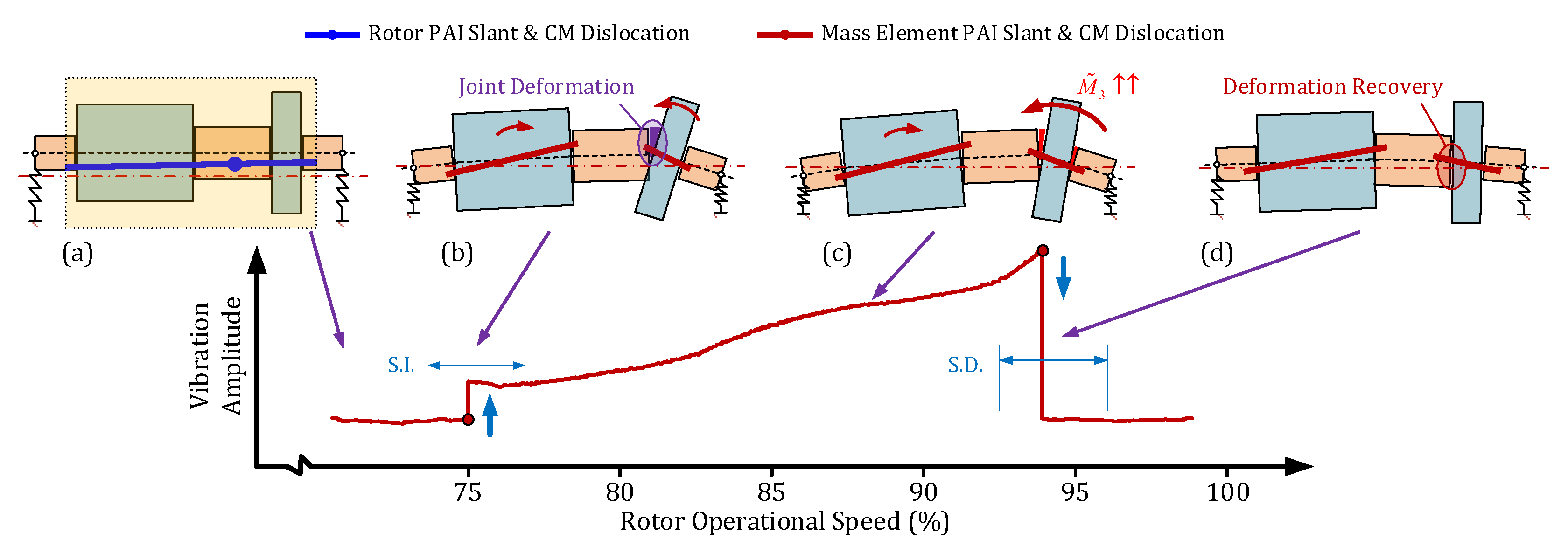
Prior to the sudden angular deformation of the joint, the bending moment applied to the joints follows a pattern: it gradually increases with operational speed, reaches a maximum at the position of the first critical speed, and then decreases. This pattern is a result of the bending moment primarily originating from the rotational inertia force generated by the rotor’s CM offset.
(b)
After the joint before the turbine element undergoes sudden angular deformation, it generates a large rotational inertia moment at high speeds owing to the additional slant of the PAI of the turbine element. This results in a significant increase in the bending moment applied to the rotor joint. Among the four joints, the joint before the turbine disk experiences the highest bending moment because it is closest to the turbine element.
(c)
As the operational speed continues to increase, the bending moment applied to the joints also increases because the rotational inertia moment generated by the slanted thin disk continues to rise with operational speed. Once the bending moment is applied to the joint before the turbine element reaches a certain threshold M t , the joint interfaces experience a slip, leading to a sudden reduction in joint angular deformation and the disappearance of the slant in the turbine element. Consequently, the rotational inertia moment from the turbine element also decreases significantly, resulting in a sudden decrease in the bending moment load applied to the rotor joints.

4. Failure Mechanism and Troubleshooting Measures

4.1. Failure Process of Rotor Vibration Failure

According to the observed failure phenomena and simulations of the dynamic response of the jointed high-speed rotor system, the rotor vibration process can be described as illustrated in Figure 18:
(1)
When the operational speed of the HPR has just passed the first and second critical speeds, the bearing load is small and changes minimally with the operational speed owing to the inward turn of the rotor’s CM.
(2)
Once the operational speed exceeds a certain threshold, the non-axisymmetric bolt preload of the joint before the turbine disk causes a sudden angular deformation of this joint. This results in a slanting of the turbine’s PAI and an increase in the additional rotational inertia moment that grows rapidly with the rotor’s operational speed. Consequently, the bearing load and the bending moment applied to the joint before the turbine increase.
(3)
As the speed continues to increase, the rotational inertia moment generated by the turbine disks keeps growing until the bending moment is applied to the joint before the turbine surpasses a certain threshold. This triggers non-axisymmetric slip at the joint interfaces and leads to the redistribution of unbalance in the HPR. The PAI of the turbine disk momentarily coincides with the rotor’s rotation axis again, causing a drop in the rear bearing load.
Therefore, the rotor vibration failure mainly originates from two aspects: (a) improper control of the slant of the turbine disk, resulting in the generation of a rotational inertia moment at high speeds, which causes bending deformation of the rotor and affects the axial distribution of the rotational inertia moment excitation load. (b) Poor contact between the rotor joints leads to interfacial slip when the joints experience the bending moment. This causes the turbine disk, which is a thin disk, to suddenly slant, thereby amplifying the impact of rotor bending deformation on the distribution of rotational inertia moment excitation and rotor dynamic response.

4.2. Troubleshooting Measures toward Rotor Vibration Failure

Considering the identified failure process, the troubleshooting measures shown in Table 3 are implemented to control the rotational inertia moment and suppress joint deformation. Engine tests confirm the effectiveness of these measures in eliminating vibration failure. This provides evidence for the accuracy of the above-described failure mechanism and the successful implementation of the troubleshooting measures.

5. Conclusions

This paper investigates the vibration failure of the HPR in a dual-spool low-bypass-ratio turbofan engine. The failure phenomenon is analyzed, and a dynamic model of the jointed high-speed rotor system is established to simulate the dynamic response of the HPR and reveal the mechanism behind the rotor vibration failure. Troubleshooting measures are proposed, and their effectiveness is demonstrated through engine tests. The conclusions of the research are as follows:
(1)
As the HPR operates at high operational speeds, it undergoes bending deformation, inducing angular displacement between the turbine and compressor elements. At low operational speeds, the dynamics are predominantly influenced by the rotor’s CM offset. Conversely, at higher speeds, the slant of the turbine disk’s PAI and the associated rotational inertia moment become dominant excitation factors. This causes the rotor dynamic responses to increase with the operational speed in the supercritical domain.
(2)
The non-axisymmetric contact at the bolt joint before the turbine induces an asymmetrical slip within the joint interfaces. This leads to angular deformation in the joint, resulting in a slant in the turbine disk’s PAI. This condition then triggers a sudden increase in the rotor dynamic response. As the speed increases, the rotational inertia moment also amplifies. Once this moment reaches a critical threshold that induces an opposite angular deformation in the joint, the turbine reverts to its initial angular position, causing a sudden decrease in the rotor dynamic response. Notably, these joint deformations are consistent with interface damages identified in faulty engines.
(3)
Troubleshooting measures are proposed to control the rotational inertia moment induced by the turbine disk’s PAI slant and the deformation of the bolt joint before the turbine disk. These measures effectively prevent the recurrence of rotor vibration failure, validating the accuracy of the mechanism analysis and the efficacy of the troubleshooting measures.
(4)
To prevent similar aero-engine vibration issues fundamentally from the design phase, a robust structural design should be emphasized to mitigate joint deformations from operational loads, including axial force, bending moment, and operational speed. Following this, simulations and tests should evaluate the design’s effectiveness.

Author Contributions

Conceptualization, F.W.; Software, X.C.; Validation, F.W.; Investigation, Y.M.; Resources, F.W.; Data curation, X.C.; Writing—original draft, F.W.; Writing—review & editing, J.H.; Supervision, Y.M.; Project administration, X.C. All authors have read and agreed to the published version of the manuscript.

Funding

The authors gratefully acknowledge the financial support provided by the National Science and Technology Major Project (Y2019-VIII-0011-0172) and the Science Center for Gas Turbine Project (P2021-A-I-002-002).

Data Availability Statement

Data is unavailable due to privacy.

Conflicts of Interest

The authors declare that they have no known competing financial interest or personal relationship that could have appeared to influence the work reported in this paper.

Appendix A. Solution Methodology to Rotor Dynamics

Based on Equation (8), the damping matrix of the rotor system is obtained by the Rayleigh damping model, which means
C = μ M + ν K ,
where, factor μ and ν can be obtained by
μ 2 ( 2 π f 1 ) + ν ( 2 π f 1 ) 2 = ξ n μ 2 ( 2 π f ) + ν ( 2 π f 2 ) 2 = ξ n ,
where, f 1 , f 2 represents the first and second critical speed of the rotor system, ξ n represents the damping ratio of the rotor system. According to Reference [30], ξ n is set to be 0.05 in this paper.
Assuming the displacement vector u has the form of u = u 0 e i ω t , then Equation (8) can be rewritten as
ω 2 M + i ω ( C + G ( ω ) ) + K u 0 = Q 0 ,
Finally, the displacement of the rotor system at operational speed ω can be obtained by
u 0 = ω 2 M + i ω ( C + G ( ω ) ) + K 1 Q 0

References

  1. Jeffcott, H.H. The lateral vibration of loaded shafts in the neighbourhood of a whirling speed—The effect of want of balance. Lond. Edinb. Dublin Philos. Mag. J. Sci. 1919, 37, 304–314. [Google Scholar] [CrossRef]
  2. Smith, D.M. The motion of a rotor carried by a flexible shaft in flexible bearings. Proc. Roy. Soc. 1933, 142, 92–118. [Google Scholar]
  3. Den Hartog, J.P. Mechanical Vibration; McGraw-Hill Book Company: New York, NY, USA, 1940. [Google Scholar]
  4. Timoshenko, S.P. Vibration Problems in Engineering; D. Van Nostrand: New York, NY, USA, 1955. [Google Scholar]
  5. Carnegie, W. Rotary inertia and gyroscopic effects in overhung shaft systems. Bull. Mech. Eng. Educ. 1964, 3, 191. [Google Scholar]
  6. Kikuchi, K. Analysis of unbalance vibration of rotating shaft system with many bearings and disks. Bull. JSME 1970, 13, 864–872. [Google Scholar] [CrossRef]
  7. Cruz, W.; Arzola, N.; Araque, O. Modeling, and experimental validation of the vibration in an unbalance multi-stage rotor. J. Mech. Eng. Sci. 2019, 13, 5703–5716. [Google Scholar] [CrossRef]
  8. Datz, J.; Karimi, M.; Marburg, S. Effect of Uncertainty in the Balancing Weights on the Vibration Response of a High-Speed Rotor. J. Vib. Acoust. 2021, 143, 061002. [Google Scholar] [CrossRef]
  9. Hong, J.; Yan, Q.; Sun, B.; Ma, Y. Vibration Failure Analysis of Multi-Disk High-Speed Rotor Based on Rotary Inertia Load Model. In Turbo Expo: Power for Land, Sea, and Air; American Society of Mechanical Engineers: New York, NY, USA, 2022; Volume 86076, p. V08BT26A014. [Google Scholar]
  10. Ishida, Y.; Yamamoto, T. Linear and Nonlinear Rotordynamics: A Modern Treatment with Applications; John Wiley & Sons: Hoboken, NJ, USA, 2013. [Google Scholar]
  11. Liu, Y.; Liu, H.; Wang, N. Effects of typical machining errors on the nonlinear dynamic characteristics of rod-fastened rotor bearing system. J. Vib. Acoust. 2017, 139, 011004. [Google Scholar] [CrossRef]
  12. Han, Z.; Wang, D.; Wang, Y.; Hong, J.; Cheng, R. Dynamic effects of the initial skewness of the inertial principal axis on the rotor with bolted joint. Mech. Syst. Signal Process. 2023, 200, 110564. [Google Scholar] [CrossRef]
  13. Barragan, J.M. Engine Vibration Monitoring and Diagnosis Based on On-Board Captured Data; MTU Aero Engines Gmbh Munich: Munich, Germany, 2003. [Google Scholar]
  14. Qin, Z.Y.; Han, Q.K.; Chu, F.L. Analytical model of bolted disk-drum joints and its application to dynamic analysis of jointed rotor. Proc. Inst. Mech. Eng. Part C J. Mech. Eng. Sci. 2013, 228, 55808444. [Google Scholar] [CrossRef]
  15. Qin, Z.; Han, Q.; Chu, F. Bolt loosening at rotating joint interface and its influence on rotor dynamics. Eng. Fail. Anal. 2016, 59, 456–466. [Google Scholar] [CrossRef]
  16. Luan, Y.; Guan, Z.Q.; Cheng, G.D.; Liu, S. A simplified nonlinear dynamic model for the analysis of pipe structures with bolted flange joints. J. Sound Vib. 2012, 331, 325–344. [Google Scholar] [CrossRef]
  17. Zhuo, M.; Yang, L.H.; Yu, L. Contact Stiffness Calculation and Effects on Rotordynamic of Rod Fastened Rotor. In Proceedings of the ASME 2016 International Mechanical Engineering Congress and Exposition, Phoenix, AZ, USA, 11–17 November 2016; p. V009T12A014. [Google Scholar]
  18. Hong, J.; Chen, X.; Wang, Y.; Ma, Y. Optimization of dynamics of non-continuous rotor based on model of rotor stiffness. Mech. Syst. Signal Process. 2019, 131, 166–182. [Google Scholar] [CrossRef]
  19. Ma, Y.; Ni, Y.; Chen, X. Bending stiffness loss of rod-rabbet joints and its effect on vibration response of rotor systems. Acta Aeronaut. Astronaut. Sin. 2021, 42, 223861. [Google Scholar]
  20. Yu, P.; Li, L.; Chen, G.; Yang, M. Dynamic modelling and vibration characteristics analysis for the bolted joint with spigot in the rotor system. Appl. Math. Model. 2021, 94, 306–331. [Google Scholar] [CrossRef]
  21. Shi, W.; Zhang, Z. Elastostatic properties for flange-bolted joints. Int. J. Press. Vessel. Pip. 2023, 205, 104966. [Google Scholar] [CrossRef]
  22. Jaszak, P. Prediction of the durability of a gasket operating in a bolted-flange-joint subjected to cyclic bending. Eng. Fail. Anal. 2021, 120, 105027. [Google Scholar] [CrossRef]
  23. Liu, S.; Ma, Y.; Zhang, D.; Hong, J. Studies on dynamic characteristics of the joint in the aero-engine rotor system. Mech. Syst. Signal Process. 2012, 29, 120–136. [Google Scholar]
  24. Liu, Y.; Liu, H.; Fan, B.W. Nonlinear dynamic properties of disk-bolt rotor with interfacial cutting faults on assembly surfaces. J. Vib. Control. 2018, 24, 4369–4382. [Google Scholar] [CrossRef]
  25. Zhao, B.; Sun, Q.; Zhao, R.; Yang, Y.; Sun, K.; Mu, X. Mass-eccentricity nonlinear evolution mechanism of combined rotor in fretting slip process. Tribol. Int. 2023, 179, 108195. [Google Scholar] [CrossRef]
  26. Chen, X.; Ma, Y.; Hong, J. Vibration suppression of additional unbalance caused by the non-continuous characteristics of a typical aero-engine rotor. In Proceedings of the 10th International Conference on Rotor Dynamics–IFToMM, Rio de Janeiro, Brazil, 23–27 September 2018; Springer: New York, NY, USA, 2018; pp. 34–48. [Google Scholar]
  27. ISO 21940-11:2016; Mechanical Vibration—Rotor Balancing—Part 11: Procedures and Tolerances for Rotors with Rigid Behaviour. Available online: https://www.iso.org/standard/54074.html (accessed on 16 October 2023).
  28. Hong, J.; Yang, Z.; Wang, Y.; Cheng, R.; Ma, Y. Combination resonances of rotor systems with asymmetric residual preloads in bolted joints. Mech. Syst. Signal Process. 2020, 183, 109626. [Google Scholar] [CrossRef]
  29. Zhao, B.; Sun, Q.; Yang, Y.; Sun, K.; Liu, Z. Study on interface non-uniform slip of combined rotor considering real preload distribution. Tribol. Int. 2022, 169, 107482. [Google Scholar] [CrossRef]
  30. Chandra, N.H.; Sekhar, A.S. Swept sine testing of rotor-bearing system for damping estimation. J. Sound Vib. 2014, 333, 604–620. [Google Scholar] [CrossRef]
Figure 1. Typical dual-spool low-bypass-ratio turbofan engine: (a) structure of the engine and the position of vibration measurement; (b) bolt joint located before high-pressure turbine disk.
Symmetry 15 01937 g001
Figure 2. Amplitude and frequency composition of the vibration in the fault engine achieved by the accelerometer at Point A: (a) vibration amplitude with the change in the operational speed of the rotors; (b) frequency composition of the engine vibration (in time interval T).
Symmetry 15 01937 g002
Figure 3. Phase of the 1x RPM vibration of HPR at points A and B: ω H —operational speed of the HPR; a E —vibration amplitude of the engine; p A , p B —vibration amplitude of point A and point B.
Symmetry 15 01937 g003
Figure 4. Loosening torque distribution of rotor joints.
Symmetry 15 01937 g004
Figure 5. Damage at the interface of the bolt joint located before the turbine: (a) Bolt joint located before the high-pressure turbine; (b) microscopic examination of interface damage on the turbine disk’s front-end face, using bolt 48# as an example; (c) 3D modeling of stains, the red and white circle represnet the start point and the end point of the cross-section of the stains; (d) Stain profile at the cross section shown in subfigure (c), allowing for determination of stain thickness.
Symmetry 15 01937 g005
Figure 6. Thickness of the stains varies across different bolt sectors.
Symmetry 15 01937 g006
Figure 7. Patterns of the indentations on the surface of bolt screws.
Symmetry 15 01937 g007
Figure 8. Distribution of indented bolts: (a) experiment results, where the orange line represents the fitted curve of the loosening torque of the bolts; (b) distribution of bolt loosening torque and indentations.
Symmetry 15 01937 g008
Figure 9. Operational loads applied to the bolt joint before the turbine disk: purple areas represent contacted area; blue areas represent the rear flange of the drum shaft; green areas represent the labyrinth disk; yellow areas represent the front flange of the turbine disk; F P represents axial compression force applied to the flange from the bolt; P E ( y ) represents contact stress from the end face; P R ( x ) represents contact stress from the centering face; F P represents bolt preload; F a , δ a represent axial force applied to the bolt joint and corresponding axial slid; F f represents frictional force of the centering face.
Symmetry 15 01937 g009
Figure 10. Angular deformation of the bolt joint before the turbine disk: blue areas represent drum shaft; green areas represent labyrinth disk; yellow areas represent turbine disk; F J , M J represent axial force and bending moment applied to the bolt joint before the turbine, α represents angular deformation of the bolt joint.
Symmetry 15 01937 g010
Figure 11. Simulation model of the bolt joint before the turbine disk: (a) a finite element model (FEM) of this bolt joint, which consists of Solid 185 elements, and the elements near the interface have been refined; (b) the boundary condition of the simulation, where blue areas represent the rear flange of the drum shaft; green areas represent the labyrinth disk; yellow areas represent the front flange of the turbine disk; F a represents axial force applied at the front end face of the drum shaft (Face A), M J represents moment load applied at Face A, ω represents the operational speed of the joint, δ a ( i ) represents axial deformation of Face A at the #i bolt caused by operational loads. Meanwhile, axial displacement constraints are applied at the rear end face of the turbine disk (Face B); (c) contact elements and bolt preload of the joint before the turbine, where F pre ( i ) represents preload in bolt #i obtained by screw elements’ pre-strain; the contact characteristics of the centering faces and end faces are obtained by Target 170/Conta 174 elements located at these surfaces.
Symmetry 15 01937 g011
Figure 12. Non-axisymmetric axial deformation of sectors with increasing operational speed and its influence on joint angular deformation: (a) angular deformation of the joint with rotor operational speed; (b) axial deformation of sectors.
Symmetry 15 01937 g012
Figure 13. Non-axisymmetric axial deformation of sectors under moment load and its influence on joint angular deformation: (a) angular deformation of the joint with the applied moment, when ω = 0.95 ω max , F a = 0.95 F a , max ; (b) axial deformation of sectors.
Symmetry 15 01937 g013
Figure 14. Rotor dynamic model with distributed excitation arising from rotational inertia load: (a) decomposition of the HPR into several elements; the high-pressure compressor with multi-disks can be treated as a single thick disk; (b) The mass, stiffness, moment of inertia, and displacement of the rotor, where m i —the mass of element i, I p , i , I d , i —the polar moment of inertia and diameter moment of inertia of element i, k θ , i —bending stiffness of element i, z ˜ i , θ ˜ i —lateral and angular displacement of element i described by the complex vector, k b , f , k b , r , c b , f , c b , r —stiffness and damping ratio of front and rear bearings, k j , j + 1 —joint bending stiffness between element j and j + 1; (c) description of the rotational inertia load applied to rotor system.
Symmetry 15 01937 g014
Figure 15. Deformation of the joint before the turbine under different operational speeds: (a) ω < ω t ; (b) ω = ω t ; (c) ω ω t   &   M ˜ J ( ω ) < M t ; (d) M ˜ J ( ω ) = M t .
Symmetry 15 01937 g015
Figure 16. Vibration amplitude and phase of the front and rear bearing of the rotor: (a) vibration amplitude; (b) vibration phase.
Symmetry 15 01937 g016aSymmetry 15 01937 g016b
Figure 17. Bending moment applied to rotor joints in response to rotor operational speed.
Symmetry 15 01937 g017
Figure 18. Process of the S.I. and S.D. of rotor vibration: (a) Rotor CM turns inward, and vibration caused by rotor CM offset decreases with operational speed. (b) The bolt joint before the turbine undergoes sudden angular deformation. (c) The rotational inertia moment arising from the slant of the turbine’s PAI increases with operational speed. (d) The rotational inertia moment reaches a threshold, and the turbine disk returns to its original angular position.
Symmetry 15 01937 g018
Table 1. Composition of the Stains on Turbine Disk’s Front-End Face.
ElementMoCrCoWZrAlNb
Bolt 18#5.1710.119.256.890.0731.160.93
Bolt 22#4.9210.059.516.770.0721.380.97
Bolt 40#4.5710.399.256.940.0771.280.91
Bolt 48#5.3910.359.126.730.0721.190.98
Substrate4.0210.779.586.990.0761.230.88
Design Value3.8–4.0510.5–11.58.5–10.56.8–10.20.07–0.091.15–1.600.85–1.05
Table 2. Rotor unbalance before and after engine experiment.
ModuleBefore Engine Test (gmm)After Engine Test (gmm)
Front B.P.Rear B.P.Static
Unbalance
Front B.P.Rear B.P.Static
Unbalance
Compressor
Module
3440∠330°2170∠158°1340∠316°3180∠314°2180∠162°1600∠275°
Turbine
Module
540∠343°1580∠201°1201∠217°1190∠210°1240∠180°2350∠195°
HPR560∠60°370∠269°300∠23°730∠47°1890∠308°1920∠330°
Table 3. Troubleshooting measures toward rotor vibration failure.
TypeMeasuresHow It Works
Rotational inertia moment controlControl initial static unbalance of turbine disk and labyrinth disk, and control initial static unbalance and initial couple unbalance of the turbine module.Control initial mass asymmetry of the components of the turbine module.
After the engine is assembled, measure and control the runout of the turbine disk rim relative to the rotor’s rotation axis.Prevent initial turbine disk slant caused by engine assembly.
Joint deformation
control
While tightening the bolts before the turbine, apply axial compressive force to assembled components.Ensure end faces are tightly attached and their contact states are uniform circumferentially during joint assembly.
Evenly select eight bolt sectors of the bolt joint before the turbine disk, and select screws with relatively large diameters to make the screw and the bolt hole nearly contact.Constrain relative displacement between flanges through screw to prevent angular deformation of the joint.
Measure and control the uniformity of bolts’ preload.Optimize circumferential evenness of the constraint of the bolts before the turbine disk.
Disclaimer/Publisher’s Note: The statements, opinions and data contained in all publications are solely those of the individual author(s) and contributor(s) and not of MDPI and/or the editor(s). MDPI and/or the editor(s) disclaim responsibility for any injury to people or property resulting from any ideas, methods, instructions or products referred to in the content.

