Unsymmetrically Distributed Bolt Axial Forces between Symmetrically Spaced Bolts of Clamping Sleeve
Abstract
1. Introduction
1.1. Uniformity with Respect to the Tightening Sequence
1.2. Bolted Connections
1.3. Measuring Bolt Axial Force
1.4. FEM Simulation
2. Materials and Methods
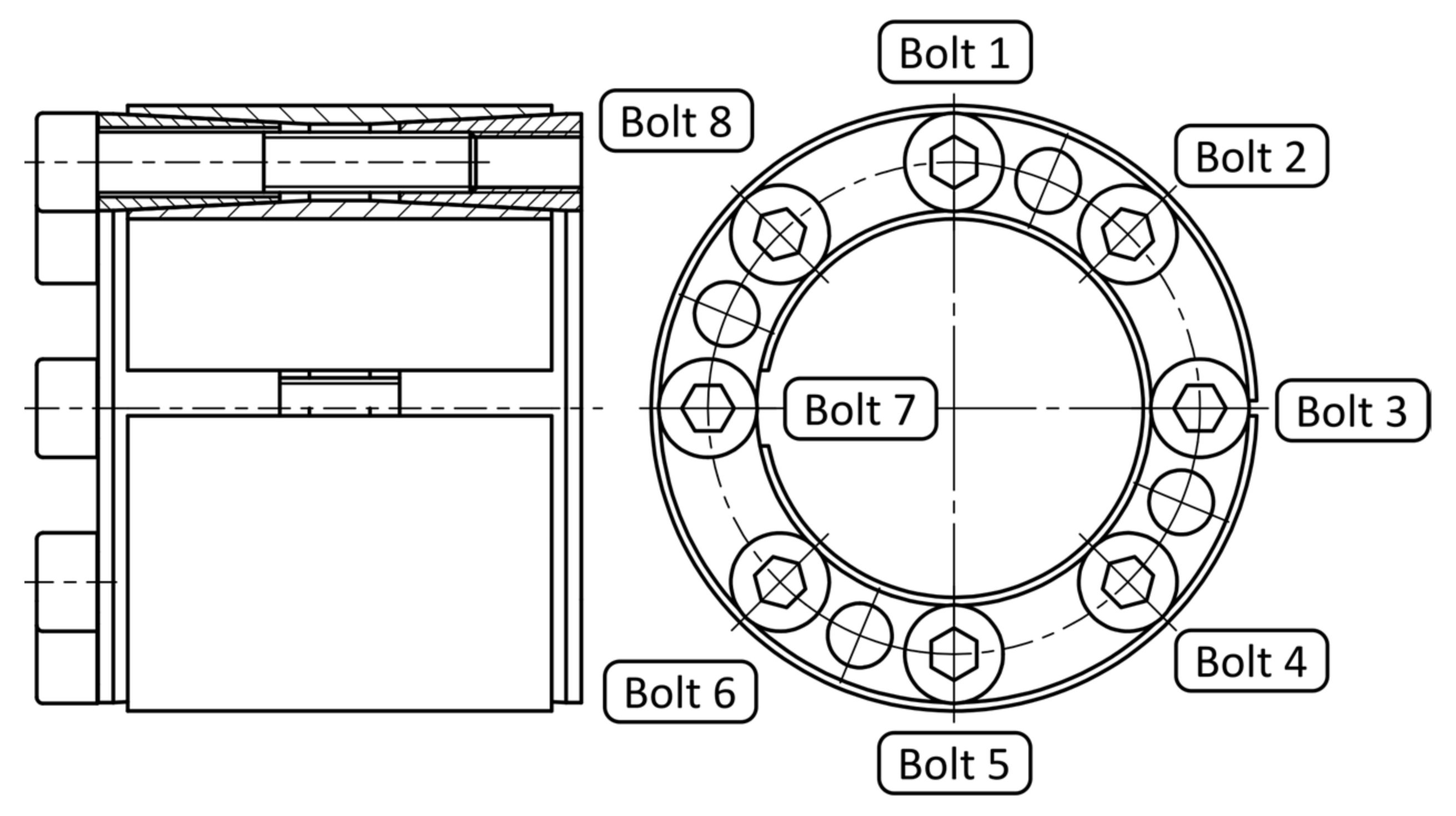
2.1. Values from the Clamping Sleeve Manufacturer’s Catalogue
- Tighten the bolts crosswise to half torque;
- Tighten the bolts crosswise to full torque;
- First time around the circumference to full tightening torque;
- Second time around the circumference to full tightening torque.
2.2. Input Data for FEM
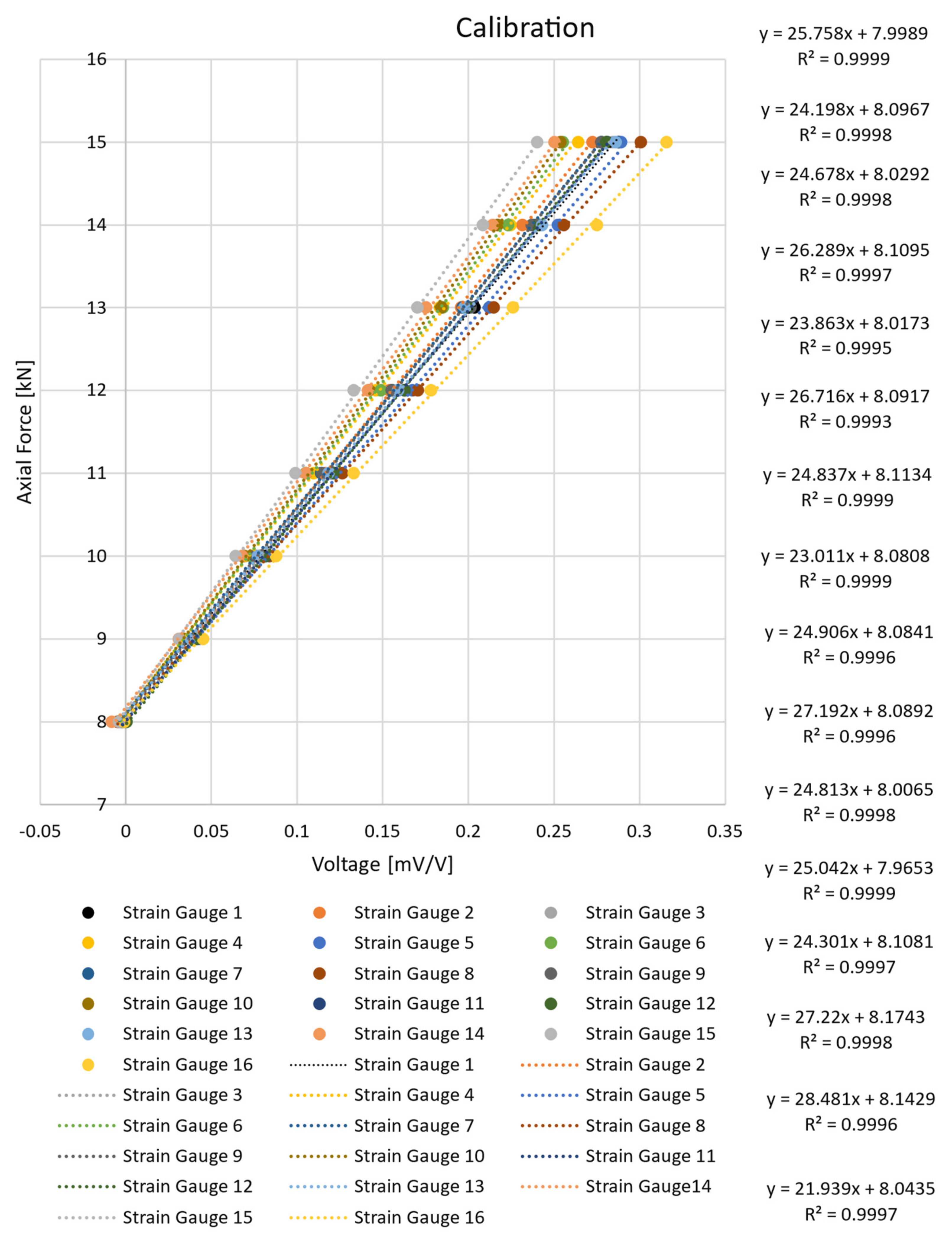
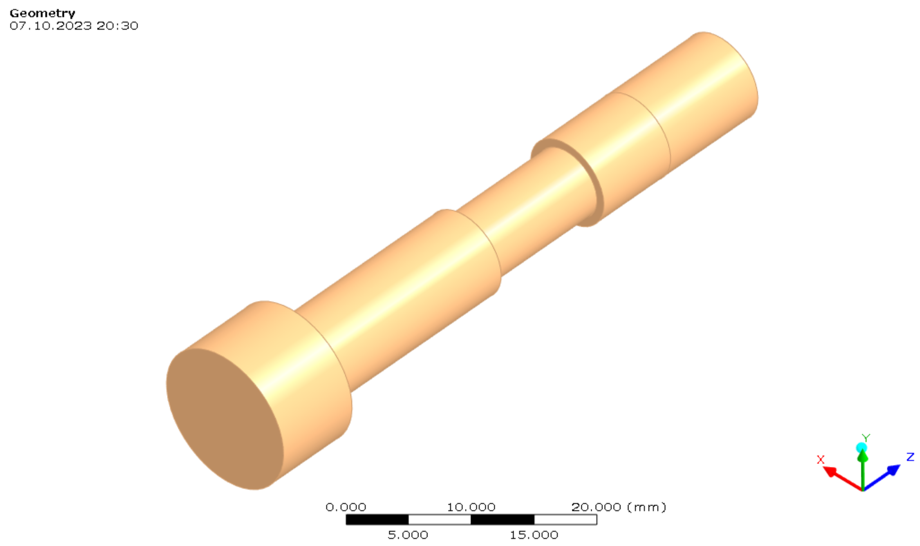
2.3. The Principle of Measurement
2.4. FEM Model Parameters
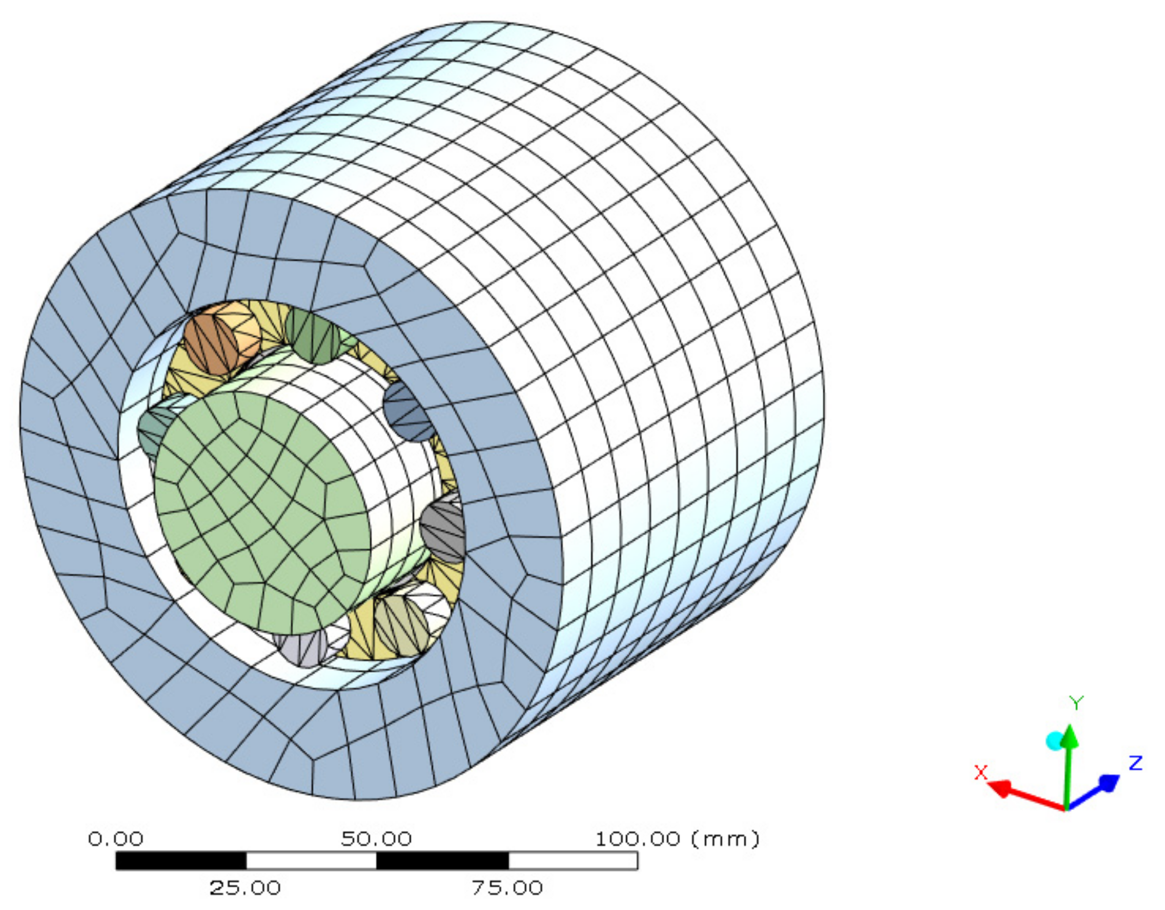
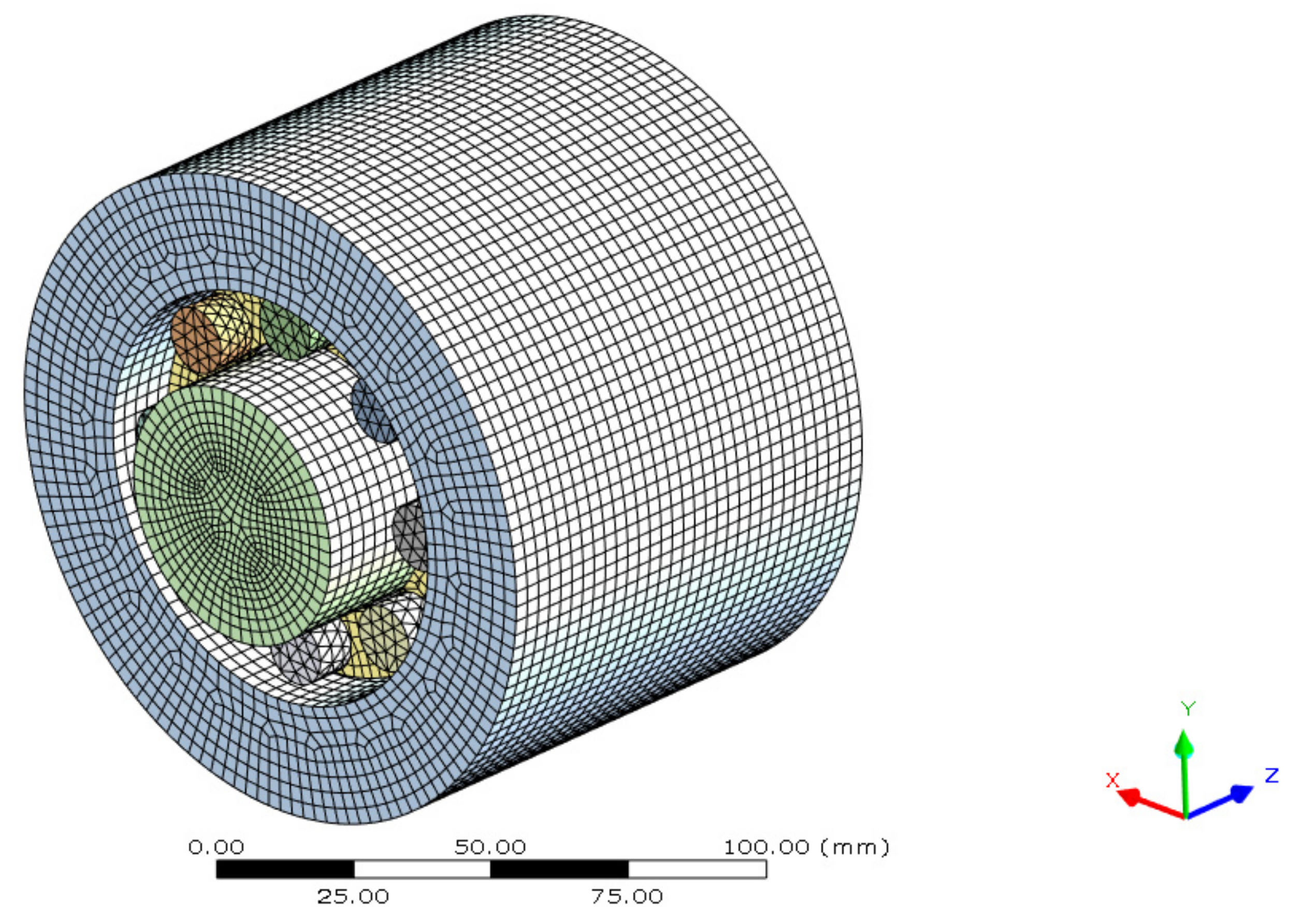
2.4.1. Geometry and Mesh
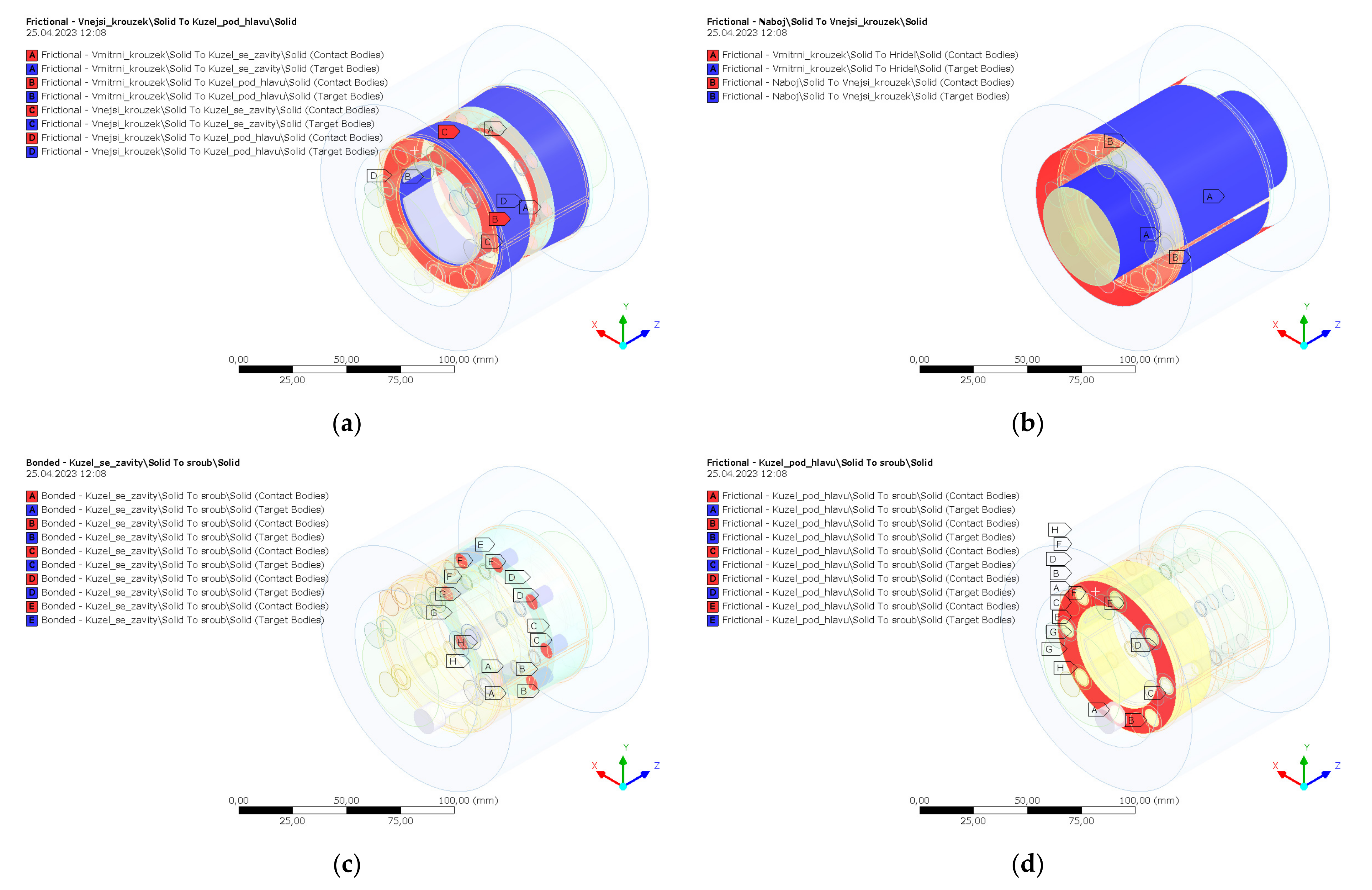
2.4.2. Contacts
2.4.3. Boundary Conditions
2.4.4. Material Properties
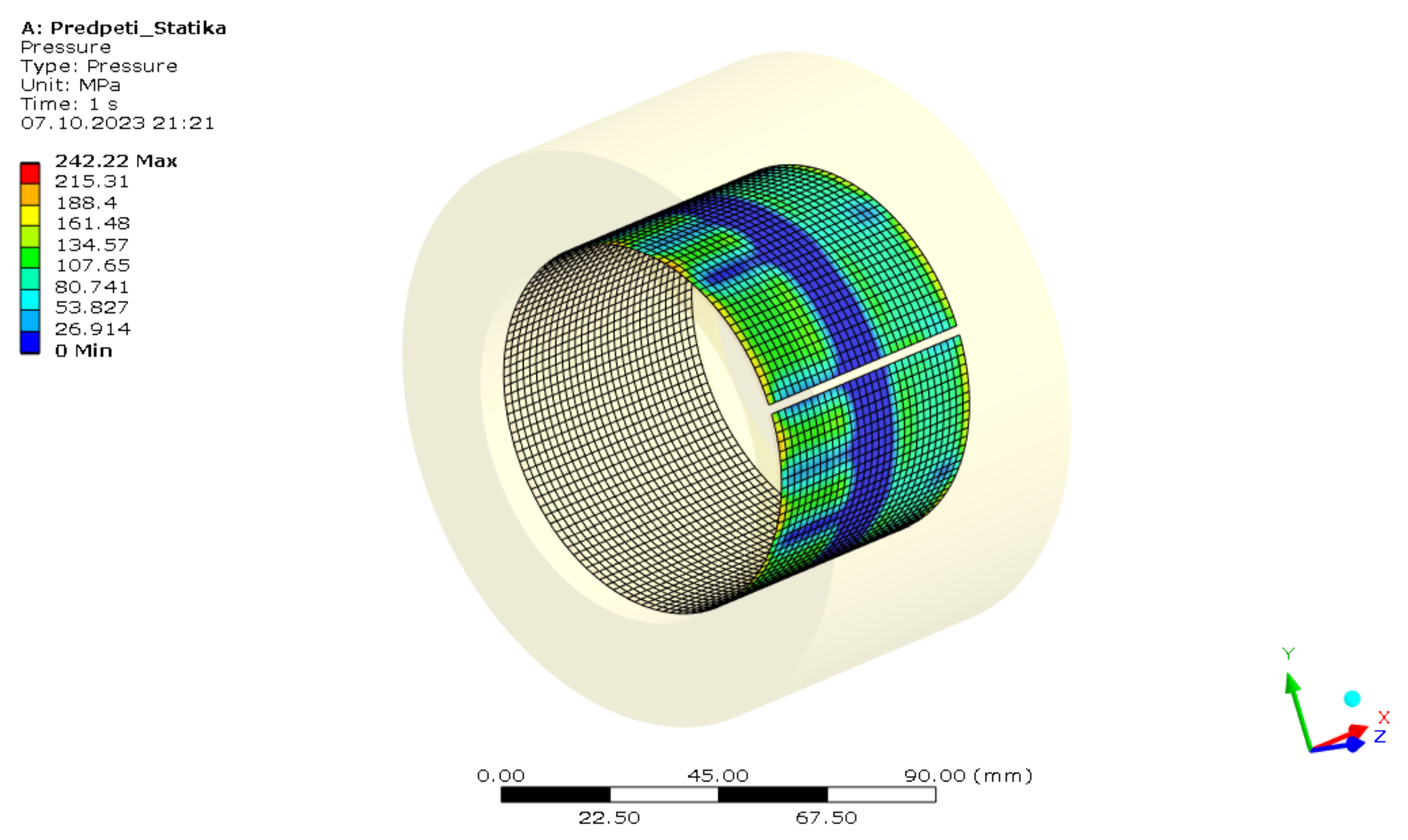
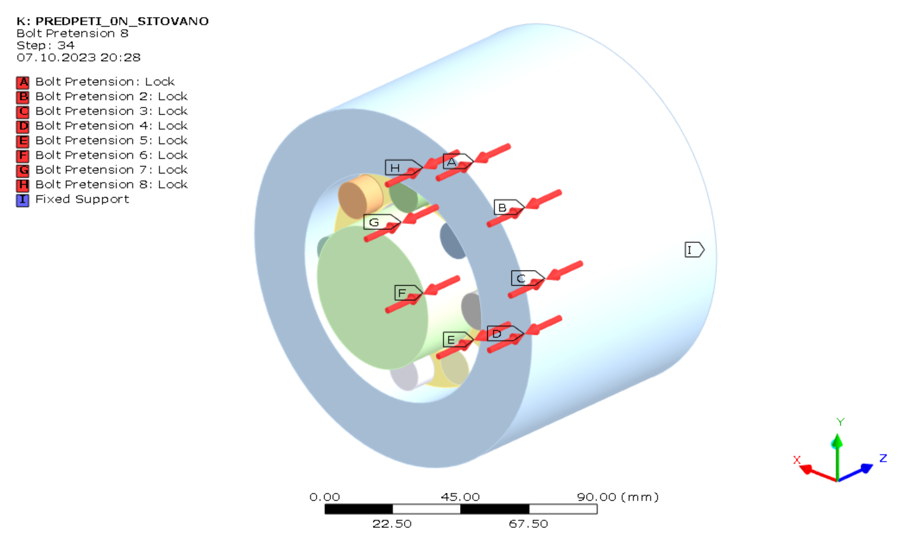
2.4.5. Loads
3. Results
3.1. Measurements Results
3.2. FEM Results
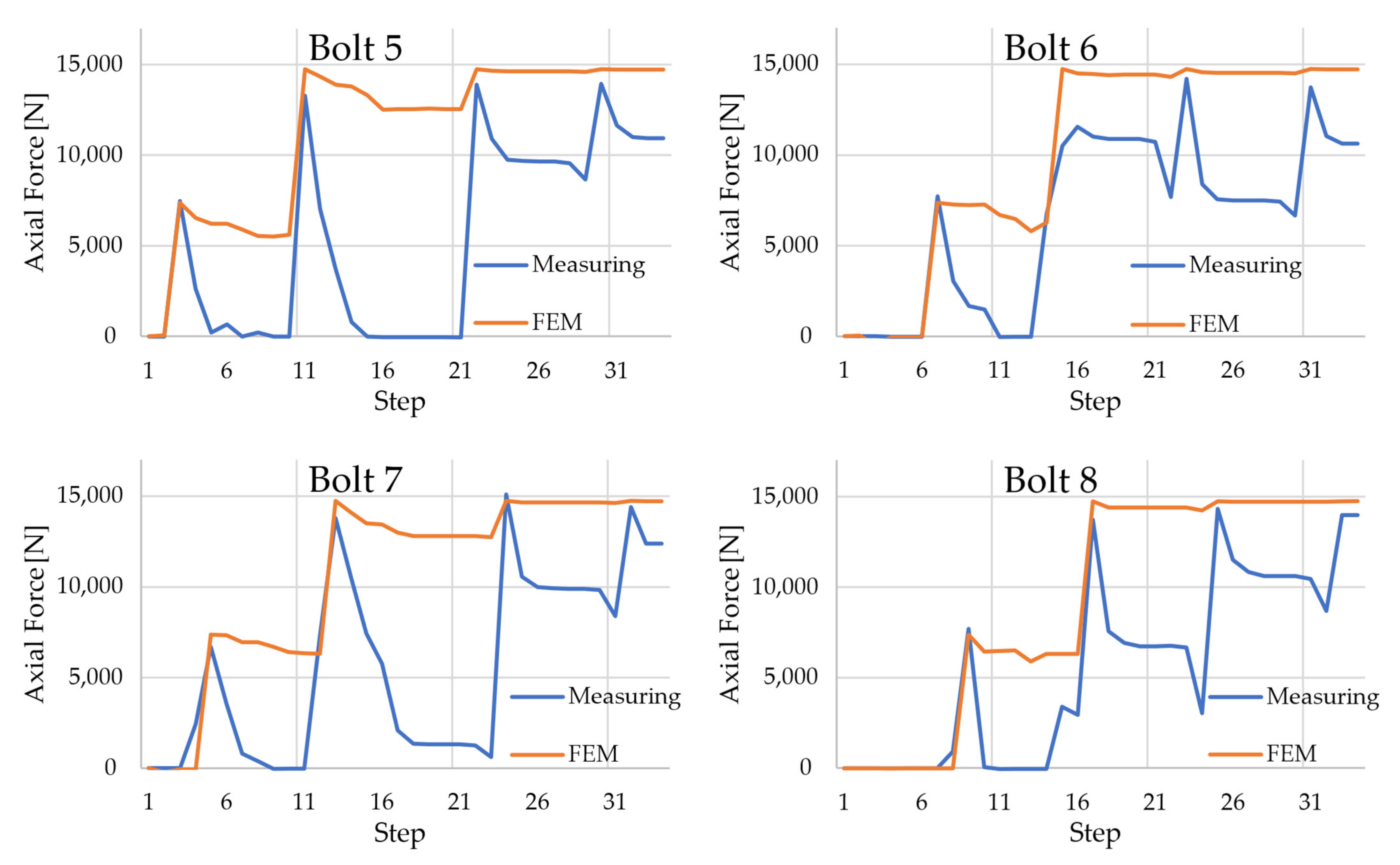
3.3. Comparison of Measurements and FEM
4. Conclusions
- Tightening based on tightening torque. Since the tightening of the sleeve is based on the tightening torque, but the axial force in the bolts is measured and required, differences in frictional properties on individual bolts will cause different axial forces in individual bolts.
- Tightening procedure according to the manufacturer’s catalog. The manufacturer’s catalog recommends tightening each bolt in sequence. From a practical perspective, the symmetrical simultaneous tightening of all bolts at the same time cannot be achieved. The only option would be to tighten with a specialized mechanical device.
- Different friction properties and surface texture. All contact surfaces of the sleeve may have different frictional properties at different points. Differences cannot be detected, so they are neglected.
Author Contributions
Funding
Data Availability Statement
Conflicts of Interest
References
- Kaláb, K.; František, O. Posudek Pevnosti, Tuhosti a Únosnosti Hřídele Hnacího Bubnu D830 Poháněcí Stanice Dopravníku BELT 1200; VŠB—TU Ostrava: Ostrava, Czech Republic, 2010. [Google Scholar]
- Kaláb, K.; František, O. Návrh a Posouzení Konstrukčních Úprav Hnacího Hřídele Dvoububnové Poháněcí Stanice 4 × 250 [KW] s Cílem Zlepšení Provozních Vlastností; VŠB—TU Ostrava: Ostrava, Czech Republic, 2010. [Google Scholar]
- Rexnord Tollok Locking Assemblies Catalog. Available online: https://www.rexnord.com/contentitems/techlibrary/documents/pt2-001m_a4_catalog (accessed on 24 May 2023).
- Lukáš, H. Analýza Vlastností Svěrných Spojů; VŠB—TU Ostrava: Ostrava, Czech Republic, 2022. [Google Scholar]
- Hashimura, S.; Komatsu, K.; Inoue, C.; Nakao, T. A New Tightening Method of Bolt/Nut Assembly to Control the Clamping Force. J. Adv. Mech. Des. Syst. Manuf. 2008, 2, 896–902. [Google Scholar] [CrossRef]
- Hashimura, S.; Sakai, H.; Kubota, K.; Ohmi, N.; Otsu, T.; Komatsu, K. Influence of Configuration Error in Bolted Joints on Detection Error of Clamp Force Detection Method. Int. J. Autom. Technol. 2021, 15, 396–403. [Google Scholar] [CrossRef]
- Yuan, S.; Zhang, Y.; Fan, Y.; Zhang, Y. A Method to Achieve Uniform Clamp Force in a Bolted Rotor with Curvic Couplings. Proc. Inst. Mech. Eng. Part E J. Process Mech. Eng. 2016, 230, 335–344. [Google Scholar] [CrossRef]
- Abid, M.; Hussain, S. Bolt Preload Scatter and Relaxation Behaviour during Tightening a 4 In-900# Flange Joint with Spiral Wound Gasket. Proc. Inst. Mech. Eng. Part E J. Process Mech. Eng. 2008, 222, 123–134. [Google Scholar] [CrossRef]
- Nassar, S.A.; Wu, Z.; Yang, X. Achieving Uniform Clamp Load in Gasketed Bolted Joints Using a Nonlinear Finite Element Model. J. Press. Vessel. Technol. Trans. ASME 2010, 132, 031205. [Google Scholar] [CrossRef]
- Abid, M.; Khan, A.; Nash, D.H.; Hussain, M.; Wajid, H.A. Simulation of Optimized Bolt Tightening Strategies for Gasketed Flanged Pipe Joints. Procedia Eng. 2015, 130, 204–213. [Google Scholar] [CrossRef][Green Version]
- Zacal, J.; Pavlik, J.; Kunzova, I. Influence of shape of pressure vessel shell on bolt working load and tightness. MM Sci. J. 2021, 12, 5448–5451. [Google Scholar] [CrossRef]
- Bolt-Tightening Handbook. Linear Motion & Precision Technologies; Guide Du Serrage GB 11; The SKF Group: Singapore, 2001.
- VDI-Fachbereich Getriebe und Maschinenelemente. Systematische Berechnung Hochbeanspruchter Schraubenverbindungen—Mehrschraubenverbindungen (Systematic Calculation of Highly Stressed Bolted Joints Multi Bolted Joints); VDI 2230 Blatt 2/Part 2; VDI-Handbuch Produktentwicklung und Konstruktion: Düsseldorf, Germany, 2014. [Google Scholar]
- Grzejda, R. Impact of Nonlinearity on Bolt Forces in Multi-Bolted Joints: A Case of the Assembly Stage. Sci. Iran. 2019, 26, 1299–1306. [Google Scholar] [CrossRef]
- Grzejda, R. Non-Linearity of the Contact Layer between Elements Joined in a Multi-Bolted Connection and the Preload of the Bolts. Combust. Engines 2016, 165, 3–8. [Google Scholar] [CrossRef]
- Grzejda, R. Study of the Distribution of Bolt Forces in a Multi-Bolted System under Operational Normal Loads. In Proceedings of the AIP Conference Proceedings, Jora Wielka, Poland, 4 March 2019; American Institute of Physics Inc.: College Park, MD, USA, 2019; Volume 2078. [Google Scholar]
- Pospíšil, F. Závitová a Šroubová Spojení, 1st ed.; SNTL—Nakladatelství Technické Literatury: Praha, Czech Republic, 1968. [Google Scholar]
- VDI-Fachbereich Getriebe und Maschinenelemente. Systematische Berechnung hochbeanspruchter Schraubenverbindungen—Zylindrische Einschraubenverbindungen (Systematic Calculation of Highly Stressed Bolted Joints Joints with One Cylindrical Bolt); VDI 2230 Blatt 1; VDI-Handbuch Produktentwicklung und Konstruktion: Düsseldorf, Germany, 2015. [Google Scholar]
- Molnár, L.; Váradi, K.; Liktor, B. Stress Analysis of Bolted Joints Part I. Numerical Dimensioning Method. Mod. Mech. Eng. 2014, 4, 35–45. [Google Scholar] [CrossRef]
- Meisami, F.; Moavenian, M.; Afsharfard, A. Nonlinear Behavior of Single Bolted Flange Joints: A Novel Analytical Model. Eng. Struct. 2018, 173, 908–917. [Google Scholar] [CrossRef]
- Začal, J.; Folta, Z.; Jančar, L. Design of a sensor for measurement of bolt pretension. In Proceedings of the 58th International Conference of Machine Design Departments (ICMD), Prague, Czech Republic, 7–9 September 2017; pp. 426–429. [Google Scholar]
- Goldarag, F.E.; Barzegar, S.; Babaei, A. An experimental method for measuring the clamping force in double lap simple bolted and hybrid (bolted-bonded) joints. Trans. FAMENA 2015, 39, 87–94. [Google Scholar]
- Huang, Y.H.; Liu, L.; Yeung, T.W.; Hung, Y.Y. Real-Time Monitoring of Clamping Force of a Bolted Joint by Use of Automatic Digital Image Correlation. Opt. Laser Technol. 2009, 41, 408–414. [Google Scholar] [CrossRef]
- Oman, S.; Nagode, M. Bolted Connection of an End-Plate Cantilever Beam: The Distribution of Operating Force. Stroj. Vestn./J. Mech. Eng. 2017, 63, 617–627. [Google Scholar] [CrossRef][Green Version]
- Hrcek, S.; Kohar, R.; Steininger, J. Axial Stiffness for Large-Scale Ball Slewing Rings with Four-Point Contact. Bull. Pol. Acad. Sci. 2021, 69, e136725. [Google Scholar]
- Zacal, J.; Folta, Z.; Struz, J.; Trochta, M. Influence of Symmetry of Tightened Parts on the Force in a Bolted Joint. Symmetry 2023, 15, 276. [Google Scholar] [CrossRef]
- Zhang, M.; Yang, M.; Li, P.; Gao, Y. Mechanical Behaviors of a Symmetrical Bolt Fasten Wedge Active Joint for Braced Excavations. Symmetry 2020, 12, 140. [Google Scholar] [CrossRef]
- Xiaolin, C.; Yijun, L. Finite Element Modeling and Simulation with ANSYS Workbench, version number: 20140707; Taylor & Francis Group, LLC: New York, NY, USA, 2015; ISBN-13: 978-1-4398-7385-4. [Google Scholar]
- Ning, K.; Wang, J.; Li, P.; Xiang, D.; Hou, D. Multi-Objective Intelligent Cooperative Design for Interference Fit of the Conical Sleeve. J. Mech. Sci. Technol. 2021, 35, 3569–3578. [Google Scholar] [CrossRef]
- Tian, Y.; Qian, H.; Cao, Z.; Zhang, D.; Jiang, D.; Lim, J.H.; Luongo, A. Identification of Pre-Tightening Torque Dependent Parameters for Empirical Modeling of Bolted Joints. Appl. Sci. 2021, 11, 9134. [Google Scholar] [CrossRef]
- Lukáš, H.; Jiří, S.; Květoslav, K. Experimental Determination of Changing the Axial Force in the Bolts of the Clamping Sleeve Under Its Axial Load. Stroj. Časopis—J. Mech. Eng. 2021, 71, 79–86. [Google Scholar] [CrossRef]
- Květoslav, K. Interaktivní a Multimediální PDF Části a Mechanismy Strojů—Teorie + Projekty. In E-Learning Systém; VŠB—TU: Ostrava, Czechia, 2018. [Google Scholar]
- HBM Test and Measurement Strain Gauge. Available online: https://www.hbm.com/fileadmin/mediapool/hbmdoc/technical/S01265.pdf (accessed on 29 August 2023).





| Tightening Moment | Axial Force | |
|---|---|---|
| Tightening to half torque at the cross | 10 Nm ± 5% | 7368.7 N |
| Tightening to full torque at the cross | 20 Nm ± 5% | 14,707 N |
| First tightening around the perimeter to full torque | 20 Nm ± 5% | 14,707 N |
| Second tightening around the perimeter to full torque | 20 Nm ± 5% | 14,707 N |
| Structural Steel | |
|---|---|
| Density | 7850 kg/m3 |
| Young’s Modulus | 2 × 10⁵ MPa |
| Poisson’s Ratio | 0.3 |
| Bolt 1 (N) | Bolt 2 (N) | Bolt 3 (N) | Bolt 4 (N) | Bolt 5 (N) | Bolt 6 (N) | Bolt 7 (N) | Bolt 8 (N) | |||
|---|---|---|---|---|---|---|---|---|---|---|
| Step | 1 | 0 | 0 | 0 | 0 | 0 | 0 | 0 | 0 | Load |
| Step | 2 | 7369 | Lock | Lock | Lock | Lock | Lock | Lock | Lock | Tightening to half torque at the cross |
| Step | 3 | Lock | Lock | Lock | Lock | 7,368,695 | Lock | Lock | Lock | |
| Step | 4 | Lock | Lock | 7369 | Lock | Lock | Lock | Lock | Lock | |
| Step | 5 | Lock | Lock | Lock | Lock | Lock | Lock | 7369 | Lock | |
| Step | 6 | Lock | 7369 | Lock | Lock | Lock | Lock | Lock | Lock | |
| Step | 7 | Lock | Lock | Lock | Lock | Lock | 7369 | Lock | Lock | |
| Step | 8 | Lock | Lock | Lock | 7369 | Lock | Lock | Lock | Lock | |
| Step | 9 | Lock | Lock | Lock | Lock | Lock | Lock | Lock | 7369 | |
| Step | 10 | 14,737 | Lock | Lock | Lock | Lock | Lock | Lock | Lock | Tightening to full torque at the cross |
| Step | 11 | Lock | Lock | Lock | Lock | 14,737 | Lock | Lock | Lock | |
| Step | 12 | Lock | Lock | 14,737 | Lock | Lock | Lock | Lock | Lock | |
| Step | 13 | Lock | Lock | Lock | Lock | Lock | Lock | 14,737 | Lock | |
| Step | 14 | Lock | 14,737 | Lock | Lock | Lock | Lock | Lock | Lock | |
| Step | 15 | Lock | Lock | Lock | Lock | Lock | 14,737 | Lock | Lock | |
| Step | 16 | Lock | Lock | Lock | 14,737 | Lock | Lock | Lock | Lock | |
| Step | 17 | Lock | Lock | Lock | Lock | Lock | Lock | Lock | 14,737 | |
| Step | 18 | 14,737 | Lock | Lock | Lock | Lock | Lock | Lock | Lock | First tightening around the perimeter to full torque |
| Step | 19 | Lock | 14,737 | Lock | Lock | Lock | Lock | Lock | Lock | |
| Step | 20 | Lock | Lock | 14,737 | Lock | Lock | Lock | Lock | Lock | |
| Step | 21 | Lock | Lock | Lock | 14,737 | Lock | Lock | Lock | Lock | |
| Step | 22 | Lock | Lock | Lock | Lock | 14,737 | Lock | Lock | Lock | |
| Step | 23 | Lock | Lock | Lock | Lock | Lock | 14,737 | Lock | Lock | |
| Step | 24 | Lock | Lock | Lock | Lock | Lock | Lock | 14,737 | Lock | |
| Step | 25 | Lock | Lock | Lock | Lock | Lock | Lock | Lock | 14,737 | |
| Step | 26 | 14,737 | Lock | Lock | Lock | Lock | Lock | Lock | Lock | Second tightening around the perimeter to full torque |
| Step | 27 | Lock | 14,737 | Lock | Lock | Lock | Lock | Lock | Lock | |
| Step | 28 | Lock | Lock | 14,737 | Lock | Lock | Lock | Lock | Lock | |
| Step | 29 | Lock | Lock | Lock | 14,737 | Lock | Lock | Lock | Lock | |
| Step | 30 | Lock | Lock | Lock | Lock | 14,737 | Lock | Lock | Lock | |
| Step | 31 | Lock | Lock | Lock | Lock | Lock | 14,737 | Lock | Lock | |
| Step | 32 | Lock | Lock | Lock | Lock | Lock | Lock | 14,737 | Lock | |
| Step | 33 | Lock | Lock | Lock | Lock | Lock | Lock | Lock | 14,737 | |
| Step | 34 | Lock | Lock | Lock | Lock | Lock | Lock | Lock | Lock | Final |
| Bolt 1 (N) | Bolt 2 (N) | Bolt 3 (N) | Bolt 4 (N) | Bolt 5 (N) | Bolt 6 (N) | Bolt 7 (N) | Bolt 8 (N) | |||
|---|---|---|---|---|---|---|---|---|---|---|
| Step | 1 | 0 | 0 | 0 | 0 | 0 | 0 | 0 | 0 | Load |
| Step | 2 | 7614.22 | −15.01 | 1.51 | −20.03 | 0.53 | 0.52 | −0.46 | −3.83 | Tightening to half torque at the cross |
| Step | 3 | 1419.11 | −4.12 | −2.53 | −25.67 | 7469.60 | −1.04 | −1.66 | −5.19 | |
| Step | 4 | −25.79 | −8.67 | 5121.02 | −33.29 | 2621.93 | −4.43 | 2454.08 | −8.51 | |
| Step | 5 | −18.15 | −15.71 | 5233.22 | −36.05 | 213.74 | −4.59 | 6684.75 | −9.79 | |
| Step | 6 | 1451.00 | 5960.76 | 190.33 | 2079.66 | 657.57 | −5.72 | 3572.00 | −6.20 | |
| Step | 7 | −11.35 | 7503.16 | 349.67 | −40.12 | −16.48 | 7704.75 | 796.12 | −7.57 | |
| Step | 8 | −12.49 | 5020.45 | −16.56 | 6207.28 | 209.12 | 3043.43 | 392.01 | 920.01 | |
| Step | 9 | −10.69 | 1698.68 | −10.19 | 7395.16 | −17.53 | 1687.88 | −22.02 | 7691.23 | |
| Step | 10 | 12,953.71 | −29.03 | −0.53 | 5861.13 | −12.15 | 1473.39 | −7.68 | 64.45 | Tightening to full torque at the cross |
| Step | 11 | 11,942.56 | −23.56 | −1.20 | 517.60 | 13,264.32 | −26.64 | −9.82 | −53.06 | |
| Step | 12 | 6896.56 | −19.09 | 6882.55 | 133.53 | 7004.06 | −17.23 | 7287.41 | −42.39 | |
| Step | 13 | 3699.63 | −15.79 | 13,770.43 | −114.57 | 3697.45 | −13.69 | 13,804.47 | −36.38 | |
| Step | 14 | 2799.03 | 3295.72 | 10,732.94 | 3118.07 | 780.51 | 6768.78 | 10,586.55 | −31.82 | |
| Step | 15 | 67.88 | 11,495.77 | 7939.14 | 3056.72 | 0.98 | 10,516.96 | 7443.02 | 3384.18 | |
| Step | 16 | 78.35 | 10,711.08 | 2967.77 | 13,105.23 | −42.73 | 11,566.62 | 5768.96 | 2928.16 | |
| Step | 17 | −28.29 | 12,280.31 | 2011.35 | 12,899.30 | −38.58 | 11,017.44 | 2073.90 | 13,712.97 | |
| Step | 18 | 14,630.10 | 6128.27 | 1473.26 | 12,746.89 | −38.19 | 10,870.33 | 1343.01 | 7560.79 | First tightening around the perimeter to full torque |
| Step | 19 | 10,785.06 | 13,810.27 | 518.24 | 12,130.64 | −38.41 | 10,878.84 | 1327.74 | 6899.88 | |
| Step | 20 | 9523.61 | 7882.19 | 14,692.24 | 7110.66 | −39.64 | 10,886.50 | 1325.74 | 6727.78 | |
| Step | 21 | 9488.86 | 7431.03 | 12,030.89 | 13,481.10 | −43.19 | 10,725.94 | 1327.23 | 6736.22 | |
| Step | 22 | 9482.35 | 7384.08 | 11,151.42 | 8646.53 | 13,879.97 | 7677.90 | 1267.23 | 6743.12 | |
| Step | 23 | 9478.48 | 7362.42 | 10,928.96 | 7696.62 | 10,898.68 | 14,188.13 | 615.82 | 6656.81 | |
| Step | 24 | 9220.22 | 7367.44 | 10,933.79 | 7609.44 | 9749.03 | 8406.49 | 15,090.66 | 3042.15 | |
| Step | 25 | 6156.04 | 7191.91 | 10,937.15 | 7603.04 | 9674.63 | 7546.01 | 10,576.24 | 14,308.60 | |
| Step | 26 | 14,157.36 | 5714.81 | 10,851.89 | 7605.77 | 9651.51 | 7496.54 | 9984.79 | 11,514.25 | Second tightening around the perimeter to full torque |
| Step | 27 | 11,017.26 | 13,589.92 | 9156.77 | 7512.14 | 9653.36 | 7497.28 | 9922.25 | 10,839.88 | |
| Step | 28 | 10,148.21 | 11,186.81 | 14,247.01 | 6360.83 | 9559.49 | 7493.31 | 9889.80 | 10,599.67 | |
| Step | 29 | 10,117.85 | 10,893.15 | 12,619.06 | 13,115.20 | 8656.10 | 7446.08 | 9886.54 | 10,600.59 | |
| Step | 30 | 10,103.18 | 10,830.56 | 12,259.72 | 11,569.97 | 13,936.85 | 6665.77 | 9826.07 | 10,595.99 | |
| Step | 31 | 10,094.67 | 10,821.34 | 12,199.17 | 11,034.10 | 11,650.85 | 13,730.56 | 8389.04 | 10,450.13 | |
| Step | 32 | 9946.80 | 10,812.92 | 12,187.00 | 10,900.00 | 10,991.45 | 11,047.59 | 14,394.54 | 8693.12 | |
| Step | 33 | 8722.73 | 10,724.43 | 12,182.18 | 10,867.15 | 10,935.03 | 10,626.51 | 12,394.79 | 13,976.74 | |
| Step | 34 | 8722.73 | 10,724.43 | 12,182.18 | 10,867.15 | 10,935.03 | 10,626.51 | 12,394.79 | 13,976.74 | Final |
| Bolt 1 (N) | Bolt 2 (N) | Bolt 3 (N) | Bolt 4 (N) | Bolt 5 (N) | Bolt 6 (N) | Bolt 7 (N) | Bolt 8 (N) | |||
|---|---|---|---|---|---|---|---|---|---|---|
| Step | 1 | 0 | 0 | 0 | 0 | 0 | 0 | 0 | 0 | Load |
| Step | 2 | 7368.69 | −12.60 | −202.75 | 33.45 | 71.84 | 32.90 | −222.84 | −25.01 | Tightening to half torque at the cross |
| Step | 3 | 7313.40 | −12.61 | −16.43 | −504.33 | 7368.69 | −469.42 | −39.44 | −25.01 | |
| Step | 4 | 7027.10 | −12.63 | 7368.69 | −30.31 | 6551.30 | −42.40 | −39.45 | −25.02 | |
| Step | 5 | 6736.20 | −12.63 | 7432.20 | −30.32 | 6202.50 | −42.40 | 7368.69 | −25.01 | |
| Step | 6 | 6441.70 | 7368.69 | 7160.90 | −30.32 | 6209.70 | −42.40 | 7346.60 | −25.01 | |
| Step | 7 | 6383.60 | 7261.50 | 7114.40 | −30.32 | 5881.60 | 7368.69 | 6962.40 | −25.01 | |
| Step | 8 | 6414.50 | 7230.30 | 6860.90 | 7368.69 | 5529.90 | 7269.70 | 6947.10 | −25.02 | |
| Step | 9 | 6210.80 | 7169.20 | 6828.30 | 7330.60 | 5522.60 | 7240.00 | 6698.40 | 7368.69 | |
| Step | 10 | 14,737.39 | 6265.60 | 6789.00 | 7420.30 | 5602.60 | 7256.20 | 6415.20 | 6432.50 | Tightening to full torque at the cross moment |
| Step | 11 | 14,853.00 | 6194.90 | 6672.00 | 6816.20 | 14,737.39 | 6705.00 | 6325.60 | 6456.60 | |
| Step | 12 | 14,830.00 | 5423.60 | 14,737.39 | 5846.30 | 14,334.00 | 6480.80 | 6311.20 | 6512.50 | |
| Step | 13 | 14,467.00 | 6164.60 | 14,120.00 | 6376.50 | 13,883.00 | 5811.50 | 14,737.39 | 5876.40 | |
| Step | 14 | 13,430.00 | 14,737.39 | 13,485.00 | 6376.50 | 13,791.00 | 6271.10 | 14,110.00 | 6311.20 | |
| Step | 15 | 13,408.00 | 14,746.00 | 13,477.00 | 6376.50 | 13,294.00 | 14,737.39 | 13,504.00 | 6312.90 | |
| Step | 16 | 13,455.00 | 14,643.00 | 12,890.00 | 14,737.39 | 12,508.00 | 14,500.00 | 13,434.00 | 6312.90 | |
| Step | 17 | 13,103.00 | 14,571.00 | 12,921.00 | 14,783.00 | 12,544.00 | 14,457.00 | 13,004.00 | 14,737.39 | |
| Step | 18 | 14,737.39 | 14,368.00 | 12,914.00 | 14,796.00 | 12,550.00 | 14,418.00 | 12,795.00 | 14,404.00 | First tightening around the perimeter to full torque |
| Step | 19 | 14,684.00 | 14,737.39 | 12,877.00 | 14,792.00 | 12,553.00 | 14,424.00 | 12,808.00 | 14,383.00 | |
| Step | 20 | 14,668.00 | 14,550.00 | 14,737.39 | 14,671.00 | 12,539.00 | 14,431.00 | 12,817.00 | 14,391.00 | |
| Step | 21 | 14,664.00 | 14,529.00 | 14,711.00 | 14,737.39 | 12,532.00 | 14,430.00 | 12,814.00 | 14,388.00 | |
| Step | 22 | 14,675.00 | 14,541.00 | 14,685.00 | 14,582.00 | 14,737.39 | 14,297.00 | 12,793.00 | 14,398.00 | |
| Step | 23 | 14,678.00 | 14,543.00 | 14,677.00 | 14,532.00 | 14,651.00 | 14,737.39 | 12,743.00 | 14,394.00 | |
| Step | 24 | 14,662.00 | 14,558.00 | 14,692.00 | 14,542.00 | 14,607.00 | 14,549.00 | 14,737.39 | 14,240.00 | |
| Step | 25 | 14,617.00 | 14,550.00 | 14,695.00 | 14,546.00 | 14,612.00 | 14,527.00 | 14,647.00 | 14,737.39 | |
| Step | 26 | 14,737.39 | 14,539.00 | 14,694.00 | 14,545.00 | 14,611.00 | 14,527.00 | 14,643.00 | 14,721.00 | Second tightening around the perimeter to full torque |
| Step | 27 | 14,711.00 | 14,737.39 | 14,680.00 | 14,543.00 | 14,608.00 | 14,524.00 | 14,642.00 | 14,717.00 | |
| Step | 28 | 14,711.00 | 14,732.00 | 14,737.39 | 14,539.00 | 14,608.00 | 14,523.00 | 14,641.00 | 14,716.00 | |
| Step | 29 | 14,712.00 | 14,730.00 | 14,725.00 | 14,737.39 | 14,596.00 | 14,522.00 | 14,642.00 | 14,717.00 | |
| Step | 30 | 14,712.00 | 14,731.00 | 14,723.00 | 14,727.00 | 14,737.39 | 14,513.00 | 14,641.00 | 14,718.00 | |
| Step | 31 | 14,713.00 | 14,732.00 | 14,724.00 | 14,723.00 | 14,720.00 | 14,737.39 | 14,624.00 | 14,716.00 | |
| Step | 32 | 14,712.00 | 14,733.00 | 14,724.00 | 14,723.00 | 14,715.00 | 14,724.00 | 14,737.39 | 14,706.00 | |
| Step | 33 | 14,710.00 | 14,733.00 | 14,725.00 | 14,723.00 | 14,715.00 | 14,723.00 | 14,733.00 | 14,737.39 | |
| Step | 34 | 14,710.00 | 14,733.00 | 14,725.00 | 14,723.00 | 14,715.00 | 14,723.00 | 14,732.00 | 14,737.00 | Final |
Disclaimer/Publisher’s Note: The statements, opinions and data contained in all publications are solely those of the individual author(s) and contributor(s) and not of MDPI and/or the editor(s). MDPI and/or the editor(s) disclaim responsibility for any injury to people or property resulting from any ideas, methods, instructions or products referred to in the content. |
© 2023 by the authors. Licensee MDPI, Basel, Switzerland. This article is an open access article distributed under the terms and conditions of the Creative Commons Attribution (CC BY) license (https://creativecommons.org/licenses/by/4.0/).
Share and Cite
Hruzik, L.; Struz, J.; Trochta, M.; Zacal, J. Unsymmetrically Distributed Bolt Axial Forces between Symmetrically Spaced Bolts of Clamping Sleeve. Symmetry 2023, 15, 1893. https://doi.org/10.3390/sym15101893
Hruzik L, Struz J, Trochta M, Zacal J. Unsymmetrically Distributed Bolt Axial Forces between Symmetrically Spaced Bolts of Clamping Sleeve. Symmetry. 2023; 15(10):1893. https://doi.org/10.3390/sym15101893
Chicago/Turabian StyleHruzik, Lukas, Jiri Struz, Miroslav Trochta, and Jiri Zacal. 2023. "Unsymmetrically Distributed Bolt Axial Forces between Symmetrically Spaced Bolts of Clamping Sleeve" Symmetry 15, no. 10: 1893. https://doi.org/10.3390/sym15101893
APA StyleHruzik, L., Struz, J., Trochta, M., & Zacal, J. (2023). Unsymmetrically Distributed Bolt Axial Forces between Symmetrically Spaced Bolts of Clamping Sleeve. Symmetry, 15(10), 1893. https://doi.org/10.3390/sym15101893


