


Analysis of the Melting Time of Phase Change Material in a Heat Exchanger with Sinusoidal Inner Duct


Abstract
:1. Introduction
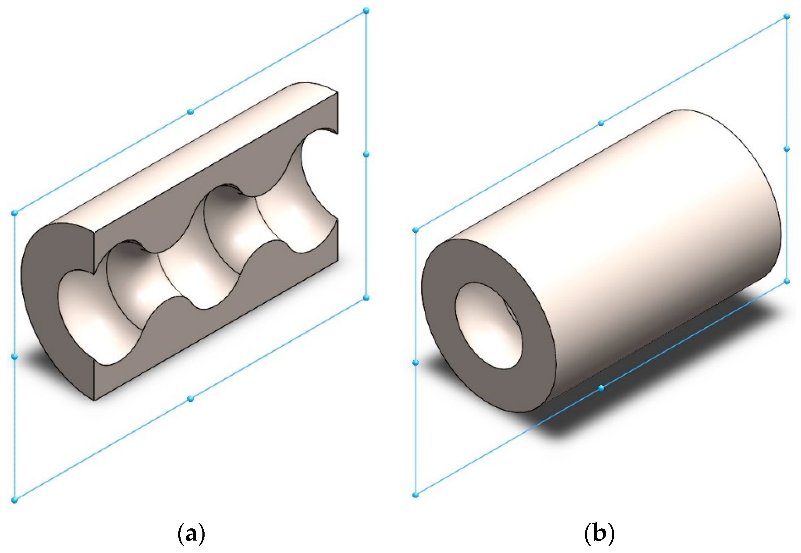
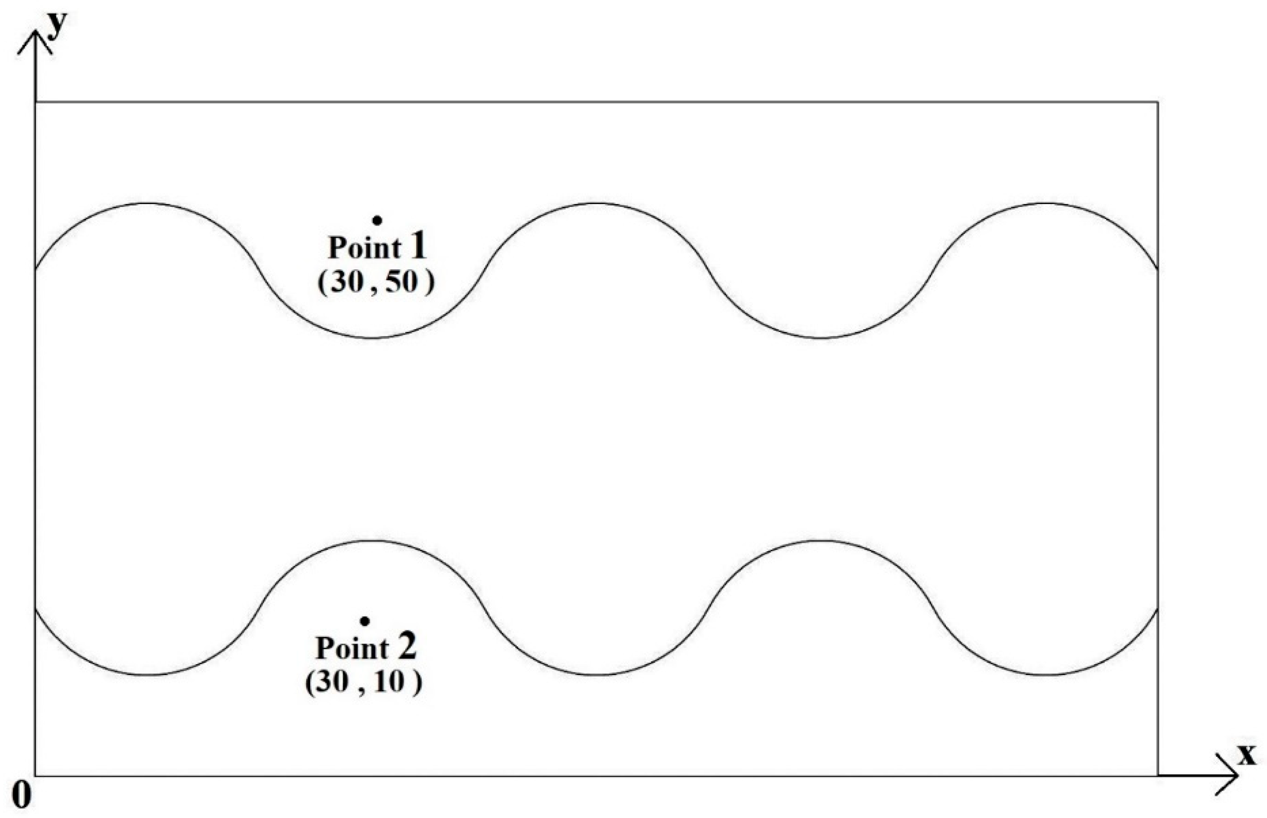
2. Physical Model
3. Governing Equations
3.1. Boundary Conditions
3.2. Solution Method
3.3. Details on PCM
3.4. Grid Distribution
3.5. Validation
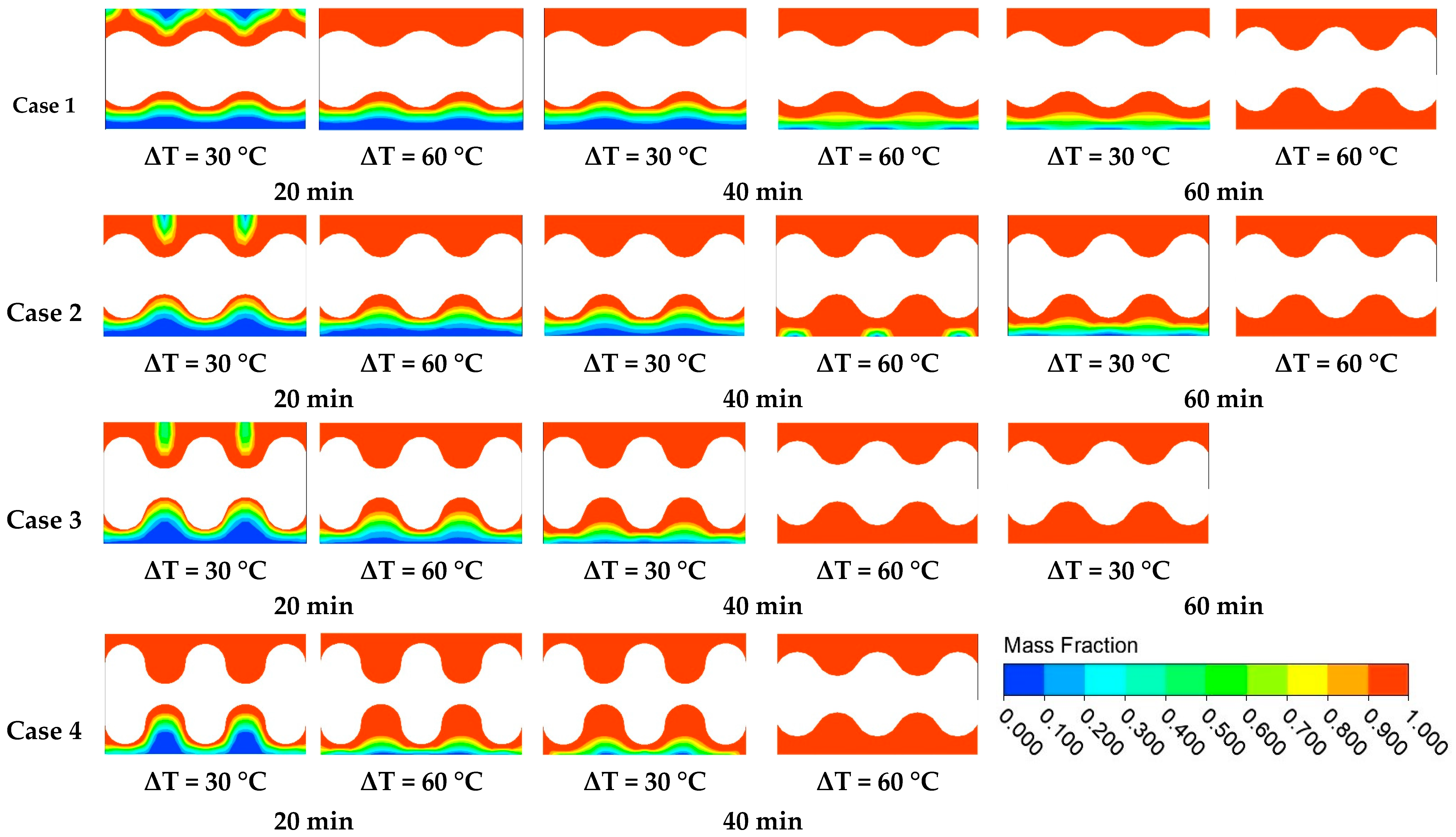
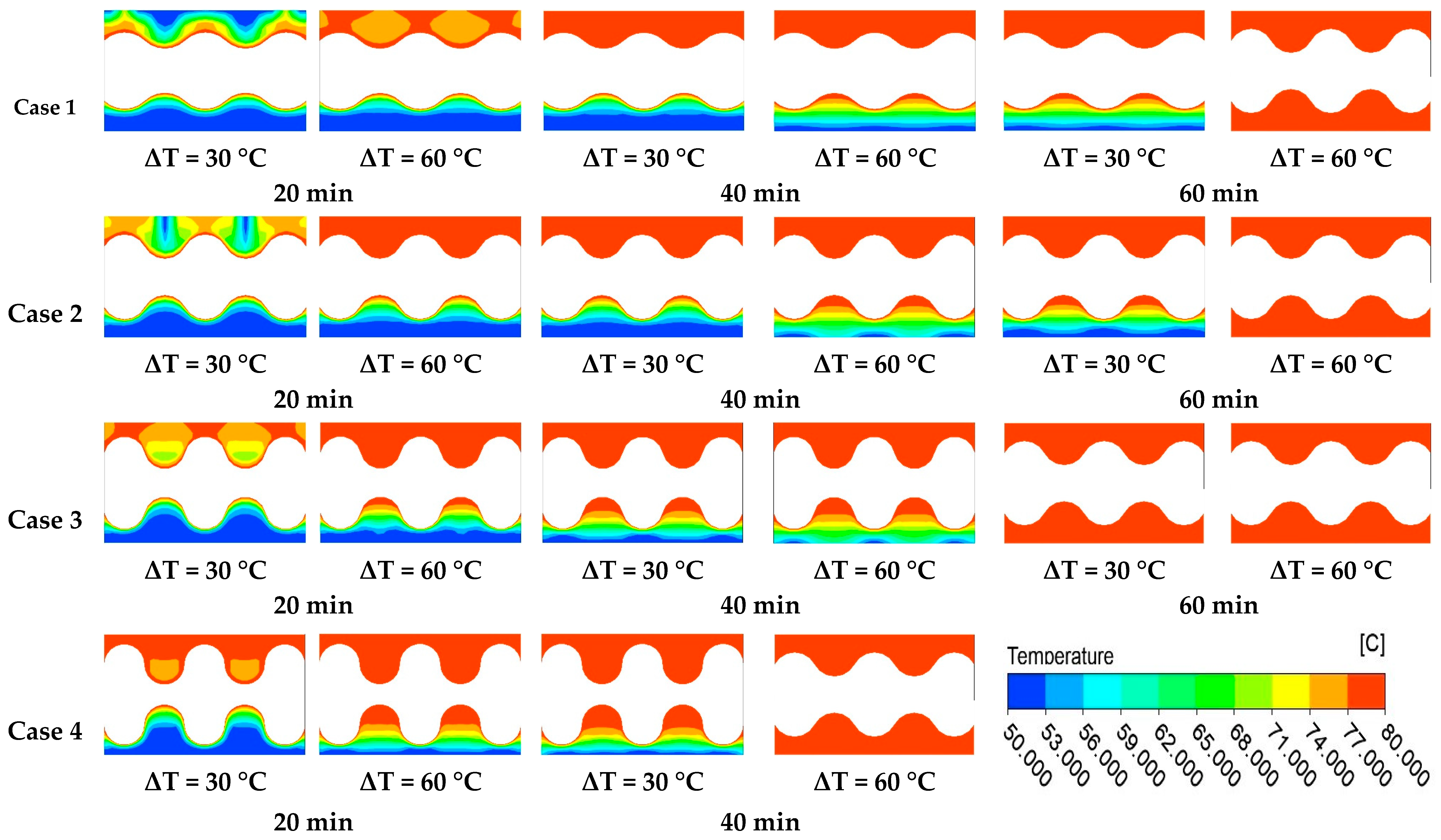
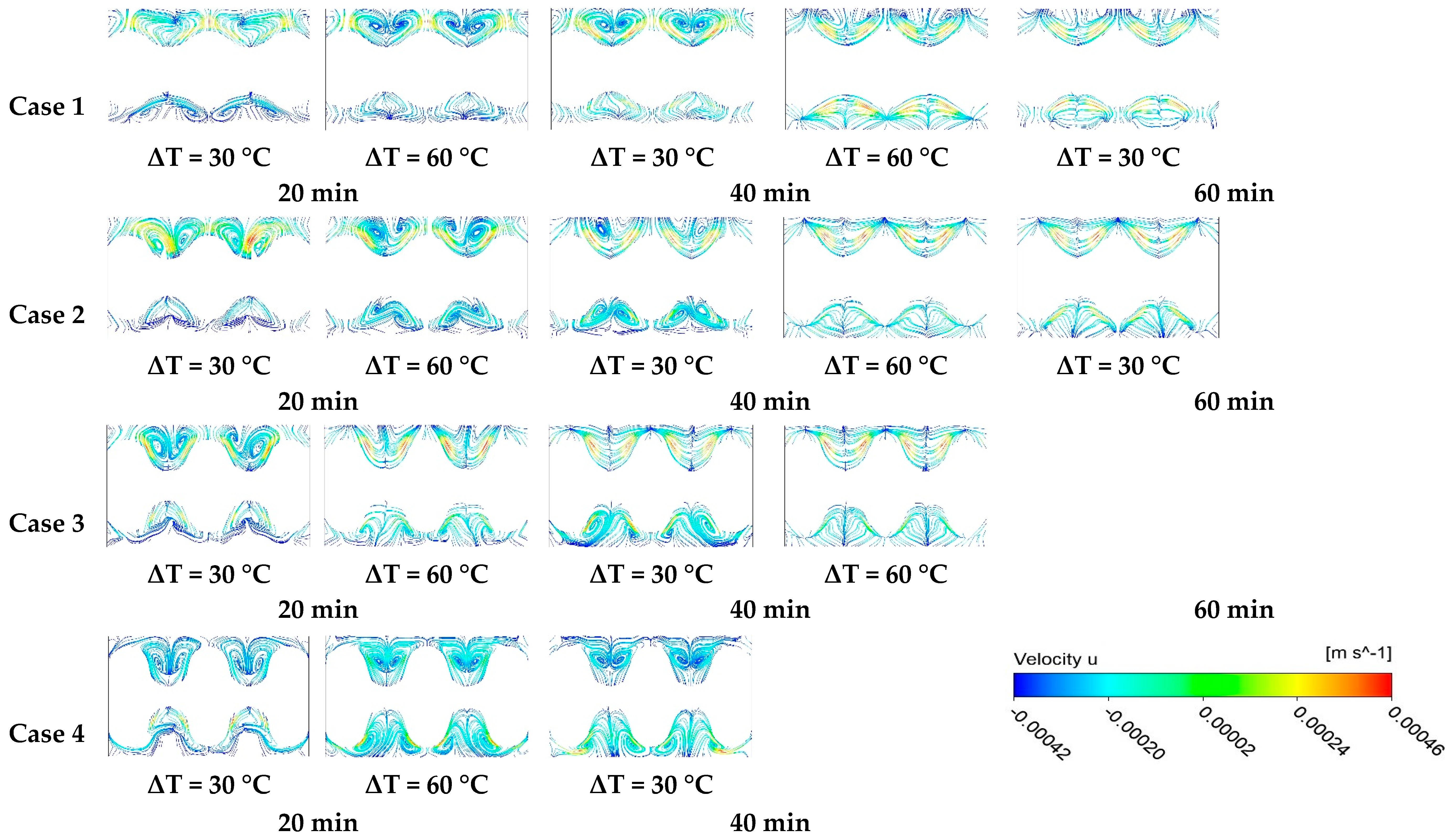
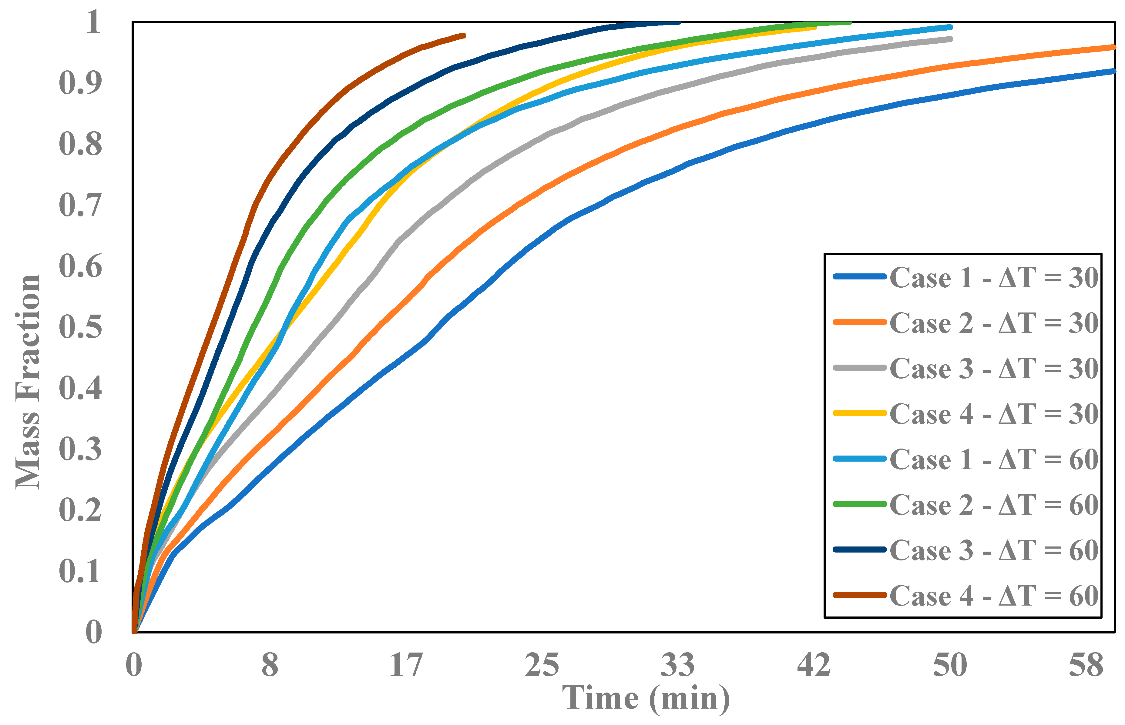
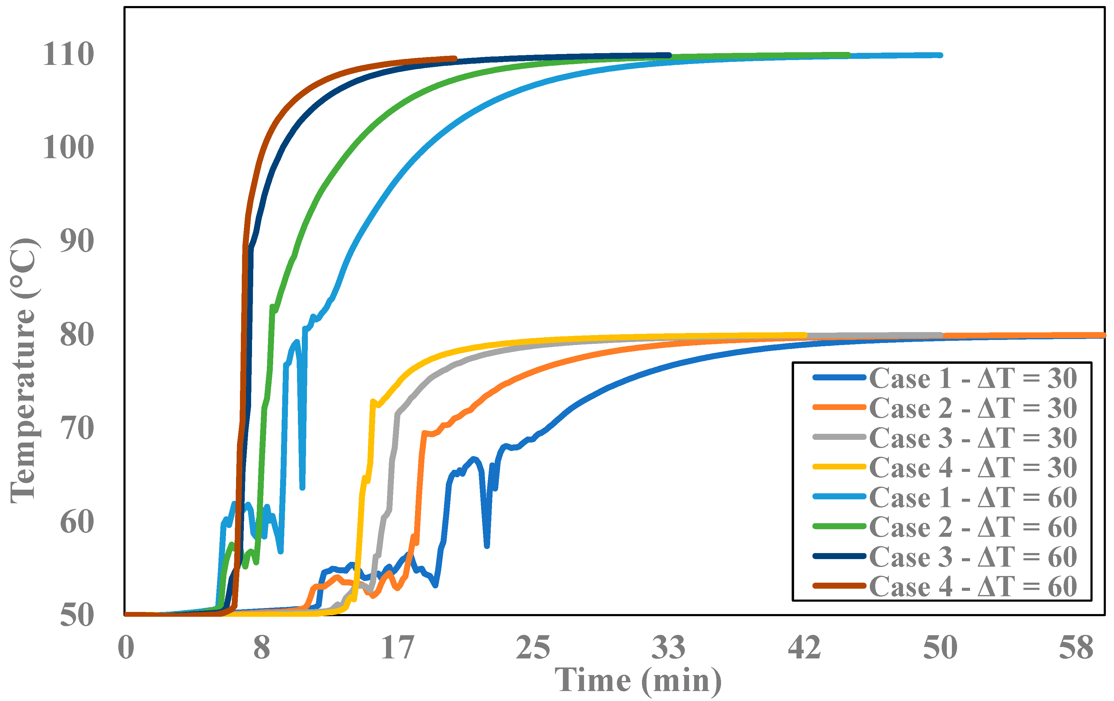
4. Results and Discussion
5. Conclusions
Author Contributions
Funding
Informed Consent Statement
Data Availability Statement
Conflicts of Interest
Nomenclature
| B | liquid fraction |
| Cp | heat capacity, J/kgK |
| gravity, m/s2 | |
| H | length of cavity, m |
| total enthalpy, J | |
| h | length of PCM, m |
| specific enthalpy, J/kg | |
| thermal conductivity, W/mK | |
| L | length of cavity, m |
| l | length of PCM, m |
| h | sensible enthapy, J/kgK |
| LH | enthalpy, J/kgK |
| local Nusselt number | |
| average Nusselt number | |
| P | pressure, N/m2 |
| Pr | Prandtl number |
| Ra | Reighley number |
| source term | |
| temperature, K | |
| time, s | |
| u | velocity, m/s |
| Greek letters | |
| thermal diffusivity, m2/s | |
| thermal expansion coefficient, 1/K | |
| dynamic viscosity, Pa.s | |
| ν | kinematic viscosity, m2/s |
| density, kg/m3 | |
| Abbreviations | |
| FVM | finite volume method |
| HT | heat transfer |
| PCM | phase change materiel |
| Subscript | |
| c | cold |
| h | hot |
| s | solid |
| l | liquid |
References
- Dormohammadi, R.; Farzaneh-Gord, M.; Ebrahimi-Moghadam, A.; Ahmadi, M.H. Heat transfer and entropy generation of the nanofluid flow inside sinusoidal wavy channels. J. Mol. Liq. 2018, 269, 229–240. [Google Scholar] [CrossRef]
- Harikrishnan, S.; Tiwari, S. Heat transfer characteristics of sinusoidal wavy channel with secondary Corrugations. Int. J. Therm. Sci. 2019, 145, 105973. [Google Scholar] [CrossRef]
- Aliabadi, M.K. Influence of different design parameters and Al2O3-water nanofluid flow on heat transfer and flow characteristics of sinusoidal-corrugated channels. Energy Convers. Manag. 2014, 88, 96–105. [Google Scholar] [CrossRef]
- Asadi, A.; Nezhad, A.H.; Sarhaddi, F.; Keykha, T. Laminar ferrofluid heat transfer in presence of non-uniform magnetic field in a channel with sinusoidal wall: A numerical study. J. Magn. Magn. Mater. 2019, 471, 56–63. [Google Scholar] [CrossRef]
- Shahsavar, A.; Al-Rashed, A.A.; Entezari, S.; Sardari, P. Melting and solidification characteristics of a double-pipe latent heat storage system with sinusoidal wavy channels embedded in a porous medium. Energy 2019, 171, 751–769. [Google Scholar] [CrossRef]
- Tang, W.; Hatami, M.; Zhou, J.; Jing, D. Natural convection heat transfer in a nanofluid-filled cavity with double sinusoidal wavy walls of various phase deviations. Int. J. Heat Mass Transf. 2017, 115, 430–440. [Google Scholar] [CrossRef]
- Dong, X.; Chen, W.; Cheng, Q.; Liu, Y.; Dai, H. Numerical analysis of thermal-hydraulic characteristics of steam-air condensation in vertical sinusoidal corrugated tubes. Int. J. Heat Mass Transf. 2021, 164, 120558. [Google Scholar] [CrossRef]
- Manjunath, M.; Karanth, K.V.; Sharma, N.Y. Numerical investigation on heat transfer enhancement of solar air heater using sinusoidal corrugations on absorber plate. Int. J. Mech. Sci. 2018, 138–139, 219–228. [Google Scholar] [CrossRef]
- Chu, W.X.; Sheu, W.; Hsu, C.; Wang, C. Airside performance of sinusoidal wavy fin-and-tube heat exchangers subject to large-diameter tubes with round or oval configuration. Appl. Therm. Eng. 2020, 164, 114469. [Google Scholar] [CrossRef]
- Modi, A.J.; Rathod, M. Comparative study of heat transfer enhancement and pressure drop for fin-and-circular tube compact heat exchangers with sinusoidal wavy and elliptical curved rectangular winglet vortex generator. Int. J. Heat Mass Transf. 2019, 141, 310–326. [Google Scholar] [CrossRef]
- Ren, Q. Enhancement of nanoparticle-phase change material melting performance using a sinusoidal heat pipe. Energy Convers. Manag. 2019, 180, 784–795. [Google Scholar] [CrossRef]
- Kurtulmus, N.; Zontul, H.; Sahin, B. Heat transfer and flow characteristics in a sinusoidally curved converging-diverging channel. Int. J. Therm. Sci. 2020, 148, 106163. [Google Scholar] [CrossRef]
- Goodarzi, M.; Mazharmanesh, S. Heat transfer enhancement in parallel-plate double-pass heat exchanger using sinusoidal separating plate. Int. J. Therm. Sci. 2013, 72, 115–124. [Google Scholar] [CrossRef]
- Li, Z.; Shahsavar, A.; Niazi, K.; Al-Rashed, A.A.; Rostami, S. Numerical assessment on the hydrothermal behavior and irreversibility of MgO-Ag/water hybrid nanofluid flow through a sinusoidal hairpin heatexchanger. Int. Commun. Heat Mass Transf. 2020, 115, 104628. [Google Scholar] [CrossRef]
- Kang, H.; Han, U.; Lim, H.; Lee, H.; Hwang, Y. Numerical investigation and design optimization of a novel polymer heat exchanger with ogive sinusoidal wavy tube. Int. J. Heat Mass Transf. 2021, 166, 120785. [Google Scholar] [CrossRef]
- Ho, C.; Hsien, T.; Chang, H.; Tu, J.-W.; Yang, C. The influences of recycle on a double-pass laminar counterflow concentric-tube heat exchangers with sinusoidal wall fluxes. Int. Commun. Heat Mass Transf. 2009, 36, 579–584. [Google Scholar] [CrossRef]
- Hong, Y.; Du, J.; Li, Q.; Xua, T.; Li, W. Thermal-hydraulic performances in multiple twisted tapes inserted sinusoidal rib tube heat exchangers for exhaust gas heat recovery applications. Energy Convers. Manag. 2019, 185, 271–290. [Google Scholar] [CrossRef]
- Moawed, M.; Ibrahim, E.; Gomaa, A. Thermal performance of a pipe in pipe heat exchanger with sinusoidal inner pipe. Energy Convers. Manag. 2008, 49, 678–686. [Google Scholar] [CrossRef]
- Akbal, Ö.; Öztop, H.F.; Abu-Hamdeh, N.H. Three-dimensional computational study in a corrugated pipe inserted system filled with phase change material. Int. J. Numer. Methods Heat Fluid Flow 2021. ahead-of-print. [Google Scholar] [CrossRef]
- Abu-Hamdeh, N.H.; Akbal, Ö.; Öztop, H.F.; MAbusorrah, A.; Bayoumi, M.M. A three-dimensional computational analysis of ellipsoidal radiator with phase change. Int. J. Numer. Methods Heat Fluid Flow 2021, 31, 2072–2087. [Google Scholar] [CrossRef]
- Mahdi, M.S.; Mahood, H.; Mahdic, J.; Khadom, A.; Campbell, A. Improved PCM melting in a thermal energy storage system of double-pipe helical-coil tube. Energy Convers. Manag. 2020, 203, 112238. [Google Scholar] [CrossRef]


| D1 (mm) | D2 (mm) | a (mm) | b (mm) | L (mm) | |
|---|---|---|---|---|---|
| Case 1 | 30 | 60 | 8 | 20 | 100 |
| Case 2 | 30 | 60 | 12 | 20 | 100 |
| Case 3 | 30 | 60 | 16 | 20 | 100 |
| Case 4 | 30 | 60 | 20 | 20 | 100 |
| Density (kg/m3) | 775 |
| Cp (Specific Heat) (j/kgC−1) | 2400 |
| Thermal Expansion Coefficient (1/K) | 9.1 × 10⁻⁵ |
| Thermal Conductivity (w/mC−1) | 0.15 |
| Dynamic Viscosity (kg/ms−1) | 0.006495 |
| Solidus Temperature (°C) | 50 |
| Liquidus Temperature (°C) | 53 |
| Pure Solvent Melting Heat (J/kg) | 243,000 |
| Element Size (mm) | Number of Nodes | Number of Elements | |
|---|---|---|---|
| Case 1 | 4 | 5952 | 4680 |
| Case 2 | 4 | 5952 | 4710 |
| Case 3 | 4 | 6912 | 5495 |
| Case 4 | 3 | 16,128 | 13,200 |
Disclaimer/Publisher’s Note: The statements, opinions and data contained in all publications are solely those of the individual author(s) and contributor(s) and not of MDPI and/or the editor(s). MDPI and/or the editor(s) disclaim responsibility for any injury to people or property resulting from any ideas, methods, instructions or products referred to in the content. |
© 2023 by the authors. Licensee MDPI, Basel, Switzerland. This article is an open access article distributed under the terms and conditions of the Creative Commons Attribution (CC BY) license (https://creativecommons.org/licenses/by/4.0/).
Share and Cite
Öztop, H.F.; Akbal, Ö.; Selimefendigil, F.; Abu-Hamdeh, N.H. Analysis of the Melting Time of Phase Change Material in a Heat Exchanger with Sinusoidal Inner Duct. Symmetry 2023, 15, 129. https://doi.org/10.3390/sym15010129
Öztop HF, Akbal Ö, Selimefendigil F, Abu-Hamdeh NH. Analysis of the Melting Time of Phase Change Material in a Heat Exchanger with Sinusoidal Inner Duct. Symmetry. 2023; 15(1):129. https://doi.org/10.3390/sym15010129
Chicago/Turabian StyleÖztop, Hakan F., Ömer Akbal, Fatih Selimefendigil, and Nidal H. Abu-Hamdeh. 2023. "Analysis of the Melting Time of Phase Change Material in a Heat Exchanger with Sinusoidal Inner Duct" Symmetry 15, no. 1: 129. https://doi.org/10.3390/sym15010129
APA StyleÖztop, H. F., Akbal, Ö., Selimefendigil, F., & Abu-Hamdeh, N. H. (2023). Analysis of the Melting Time of Phase Change Material in a Heat Exchanger with Sinusoidal Inner Duct. Symmetry, 15(1), 129. https://doi.org/10.3390/sym15010129