1. Introduction
Electromagnetic (EM) metamaterials, i.e., artificial composite structures created by the periodic arrays of conducting wires and split-ring resonators (SRRs), were shown to possess both negative permittivity and permeability frequency bands, creating a negative refraction index [
1,
2,
3,
4,
5,
6]. The EM metamaterials possess a number of peculiar properties, including inverse light pressure, a reverse Doppler effect, and opposite phase and energy velocities, which result in different capabilities for the manipulation of electromagnetic waves.
On the other hand, magneto-electro-elastic (MEE) materials have attracted exponentially increasing attention. The main reason behind this attention is that MEE structures can now convert electrical and magnetic energy due to the coupled effect between electric and magnetic fields. Because of this feature, MEE materials have been widely applied in many fields of modern technology, e.g., sensors [
7], smart devices [
8], and nondestructive evaluation [
9]. Various analytical and numerical techniques related to various MEE structures have been developed by numerous scholars. Ezzin et al. [
10] studied Love waves propagating in a transversely isotropic piezoelectric layer in a piezomagnetic half-space. Xiao et al. [
11] investigated the dispersion characteristics of guided waves in a multilayered MEE curved panel. Chen et al. [
12] investigated the dispersion and band structures of elastic waves in nanoscale periodic piezoelectric/piezomagnetic laminates. However, magneto-electro-elastic, piezoelectric, electromagnetic metamaterials (MEEPEM) have not been studied.
In this paper, we design the MEEPEM by using a square lattice of the periodic arrays of conducting wires, piezoelectric photonic crystals (PPC), and SRRs in
Section 2. We analyze the mechanism for the coupling of the longitudinal superlattice vibrations, magnetic field, and electric field. We calculate the dielectric functions by using the Plane Wave Method, reflection coefficients by using the Transfer Matrix Method, and the effective magnetic permeability of MEEPEM. By using them, we will analyze the transmission properties of EM waves in the MEEPEM in
Section 3. Conclusions are given in
Section 4. We believe that our studies can contribute to the design of EM wave devices on the basis of the MEEPEM.
2. Dielectric Functions, Reflection Coefficients, and Effective Magnetic Permeability of MEEPEM
In order to elucidate the ideal of MEEPEM, we consider a composite structure consisting of a square lattice of the periodic arrays of conducting wires, PPCs, and SRRs shown schematically in
Figure 1. In
Figure 1a, for PPC, we choose ion-doped periodically poled lithium niobate crystal with the periodic concentration of the impurities in the positive and negative domains (IPPLN). The IPPLN can be produced by the Czochralski method [
13,
14,
15], and the doping of ions does not change the symmetry of lithium niobate [
16,
17,
18]. The ion-doped concentration of the IPPLN changes periodically; thus, the physical properties of IPLLN will be periodically changed. The ferroelectric domains of the IPPLN are periodically reversed along the
x axis. We denote a and b as the thicknesses of positive and negative domains, respectively, and
mol% and
mol% (
) as ion-doped concentrations in positive and negative domains, respectively. The period of domains is
, and the duty cycle is
r = a/b. The thickness of the MEEPEM is
along the
x axis. The unit cell size of the MEEPEM is
. For simplicity, we choose the single-ring geometry of a lattice of cylindrical SRRs. The micro-structured material has been proposed and constructed to create left-handed metamaterials [
19]. The SRRs are installed on the two surfaces of PPC along the
x axis, and the directions of the gaps of the SRRs sharing a common axis are the same. The SRR can be equivalent to the
LC oscillator with the capacitance
C of the SRR gap, an effective inductance
L, and resistance
R.
Figure 1b,c show the comparison of an equivalent
LC circuit and a metallic SRR. The parameters of SRR are marked in
Figure 1b: the gap size
l1, the thickness
l2, the width
l3, and the radius
. In
Figure 1d,
is the diameter of the conducting wire.
As shown in
Figure 1a, along the
z axis, the EM waves with magnetic field
and electric field
propagate into MEEPEM. From Faraday’s law of electromagnetic induction, magnetic field
will induce electric currents in identical SRRs sharing a common axis. In addition, the currents generate an attractive Ampère force between the SRRs, which compress PPC periodically. The Ampère forces acting between the SRRs have only the axial component, calculated as [
20]:
where
K is the complete elliptic integral of the first,
E is that of the second kind,
is magnetic flux, and
where
,
, and
are the impedance, inductance, and capacitance of the SRR, respectively, and
is the relative permittivity of the material filled in the SRR gap (see
Figure 1b). We assume additional forces between the SRRs in the neighboring columns can be neglected. Because of the attractive Ampère forces between the SRRs, the stress can be calculated on the cross-sectional area of PPC along
x axis, that is,
where
S is the cross-sectional area of the PPC along
x axis,
m is the number of SRRs, and
is the periodic stress which is applied to the S of PPC. Because of the piezoelectric effect, the stress
can generate transverse electric polarization. In response to the piezoelectric effect, the periodic electric field
of the EM wave can excite a longitudinal superlattice vibration. These will result in the coupling of electric, magnetic, and acoustic fields in the MEEPEM. The piezoelectric, Maxwell, and motion equations of the three field couplings are written as follows [
21,
22,
23]:
where
where
,
,
, and
are the strain, stress, electric displacement, and electric field, respectively, and they are functions of both position
x and time
t.
, , (x), and
(x) are the piezoelectric stress, piezoelectric strain, elastic, and dielectric coefficients, respectively;
is the mass density of PPC, and they are periodic functions of position
x.
is the permeability of the vacuum. Here, the damping of materials has been neglected.
Equation (3) implies the principle that the stress and of EM wave create the longitudinal superlattice vibration . Equation (4) implies the principle that the stress and longitudinal superlattice vibration can excite additional electric polarizations. Equations (3) and (4) imply the coupling of electric, magnetic, and acoustic fields due to the piezoelectric effect in the MEEPEM, resulting in a type of polariton, called the multi-field coupling polariton.
Substituting Equation (5) into Equation (6), we obtain:
Substituting Equation (13) into Equation (4), we obtain:
where the modulation functions
and
are expressed as follows:
respectively. Using Fourier transformation, the modulation functions
and
are written as:
respectively, where
:
Applying Equation (14) to Equation (7), we obtain:
Substitution of Equation (23) into Equation (5), we have:
where
is the relative dielectric function:
where
where
. The relative dielectric function
is the function of the position
x and angular frequency ω. We assume that the wavelength of an electromagnetic wave is larger than the unit cell size
of the MEEPEM; then, the positive and negative domains of the MEEPEM can be considered homogeneous in space. With this approximation, the space average values are applicable, i.e., the positive domain
and the negative domain
]. Then, the relative dielectric function of the positive domain is written as:
where
is the resonance angular frequency of the n-order multi-field coupling polariton of the positive domain. Furthermore, the relative dielectric function of the negative domain is written as:
where
is the resonance angular frequency of the n-order multi-field coupling polariton of the negative domain. For the unit cell of the periodic arrays of conducting wires, the average macroscopic electric field is approximately equal to the local field in the long-wavelength approximation. Taking into account Equations (27) and (28), and the effective dielectric permittivity of conducting wires [
2], the expression for the relative dielectric function of the positive and negative domains of MEEPEM can be written as
and
respectively, where
is the effective plasma frequency:
where
is the velocity of light in free space, and
is the effective plasma frequency,
is the diameter of the conducting wire, and
is the unit cell size of the MEEPEM (see
Figure 1).
On the basis of the Transfer Matrix Method of the photonic crystal and the relative dielectric functions
and
of MEEPEM [
24,
25,
26], we calculate the reflection coefficients of the MEEPEM. It is derived as follows:
where
(
n1 are the refractive indexes of the media before the EM waves propagate into the MEEPEM,
is the permeability of vacuum) and
(
are the refractive indexes of the media after the EM waves propagate out of the MEEPEM) are the impedances of electromagnetic waves.
where
where
,
,
, and
.
and
are refractive indices of the positive domain and negative domain in MEEPEM, respectively.
In addition, a negative value of the magnetic permeability of the SRR in MEEPEM becomes possible (see Ref. [
27]). According to the calculation method in the Refs. [
1,
27], we obtain an explicit expression for the effective magnetic permeability
of the composite structure in the long-wavelength approximation, that is,
where
is the magnetic resonance angular frequency.
3. Results and Discussion
According to the relative dielectric function, effective magnetic permeability, and reflection coefficient, we can obtain the physical information required to study the transmission properties of EM waves in MEEPEM [
1,
21,
22,
23,
24,
25,
26,
27]. For the doped ion of IPPLN, we choose the Mg ion. The Mg ion concentrations of the positive and negative domains in MEEPEM are 0 mol% and 7 mol% [
28] (see
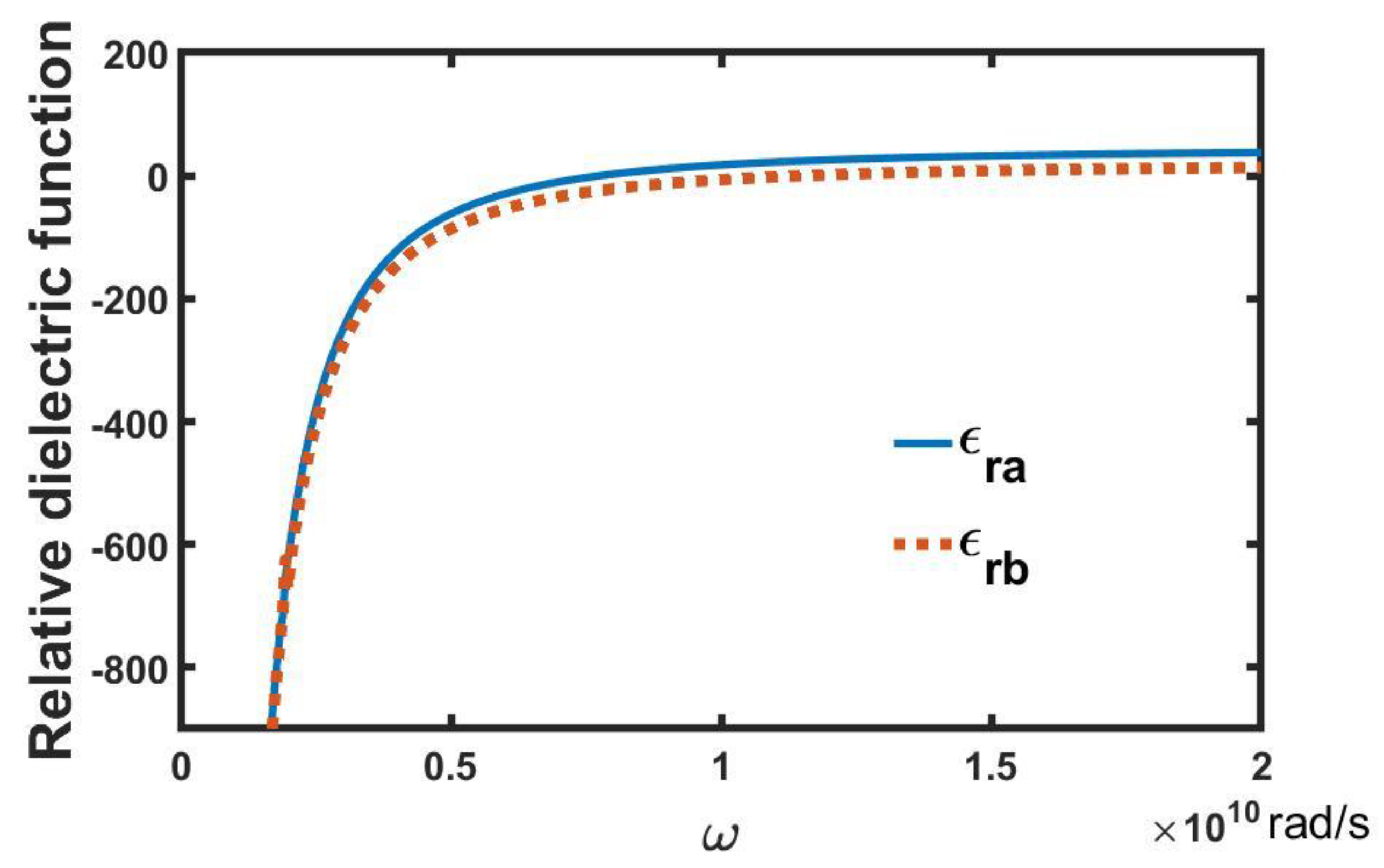
Figure 1), respectively. From Equations (27) and (28), the relative dielectric functions
and
of the first-order multi-field coupling polaritons in the MEEPEM are plotted in
Figure 2. Because the damping of the material is not considered,
Figure 2 shows only the real parts of the relative dielectric functions, and
and
are represented by the blue solid line and red dashed line, respectively. In this paper, the material parameters of the positive domain in MEEPEM are chosen from Ref. [
21]:
,
= 2.50 C/m
2,
, and
= 44.00. In addition, the proper values of the material parameters of the negative domain in MEEPEM are chosen as follows [
28,
29,
30,
31,
32]:
,
= 2.32 C/m
2,
, and
= 20.00. Other parameters include: the period Λ = 2
, the number of the period
N = 20, the duty cycle
r =
a/
b = 3,
m = 1,
= 2.0
,
= 1.26
,
S = 5.00
, the suitable values of the complete elliptic integrals of the first
K and second kind
E chosen from Refs. [
33,
34,
35],
E = 0.6, and
K = 12.
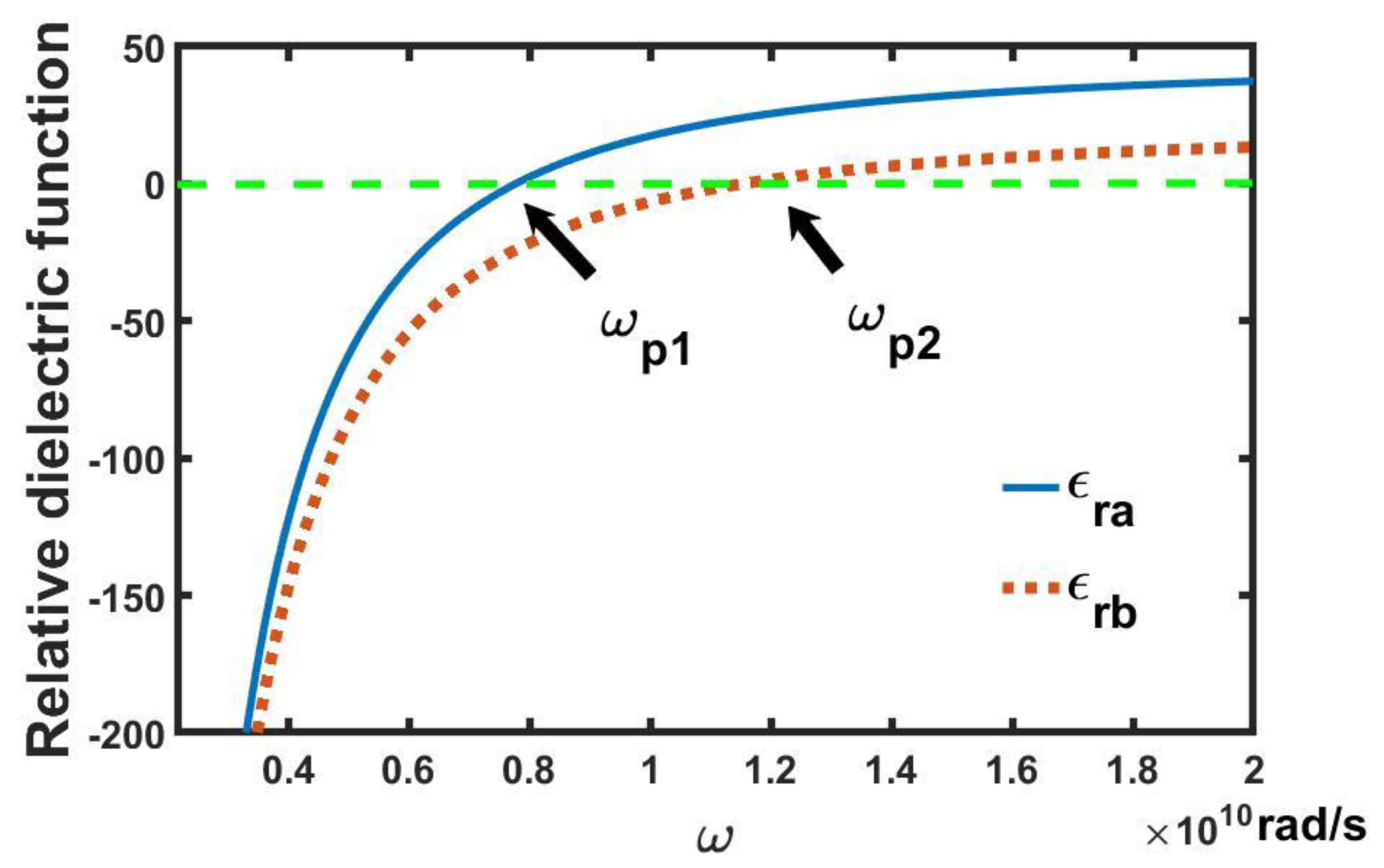
Figure 3 and
Figure 4 show the high and low angular frequency regions of the dielectric spectrum in
Figure 2, respectively. From
Figure 3, the real parts of two dielectric functions
and
in the positive and negative domains exhibit negative values below angular frequencies
and
, respectively. If we do not consider PPC and SRRs in the MEEPEM, the effective nonlinear dielectric permittivity of the periodic arrays of conducting wires is written as [
2]:
where
is the effective dielectric permittivity. From the above equation, we know
is below the effective plasma frequency
= 51.5 Grad/s. Because of PPC and SRRs in the MEEPEM, the
splits into two angular frequencies
and
,
, and
. At angular frequencies
and
,
= 0, and
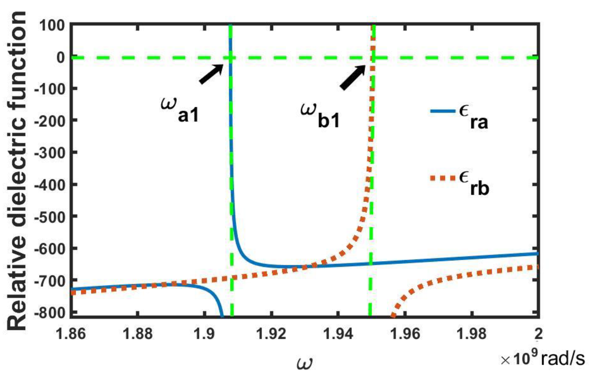
= 0, correspond to two zero refractive indices. As shown in
Figure 4, there are two dielectric abnormalities near the resonance angular frequencies
= 1.91 Grad/s and
= 1.95 Grad/s, corresponding to the first-order multi-field coupling polaritons for the coupled waves. The peaks of two dielectric abnormalities are greater than zero. At
and
,
and
, correspond to two zero refractive indices.
The results of the dielectric spectra in
Figure 2,
Figure 3 and
Figure 4 are interpreted as follows. Magnetic field
of the EM wave induces electric currents in two identical SRRs sharing a common axis, and the currents generate an attractive Ampère force between the SRRs, which periodically compress PPC, and this can create an additional electric polarization due to the piezoelectric effect. The electric field
of the EM wave can excite the longitudinal superlattice vibration in PPC, which can also create additional electric polarization. Two additional electric polarizations are coupled to the electric field excited by the periodic arrays of conducting wires. The coupled electric field is coupled to the EM wave along the
z axis. These interactions result in the coupling between the longitudinal superlattice vibrations, magnetic field, and electric field in the MEEPEM, which cause variations in the dielectric spectrum. When the EM waves propagate along the
x axis through the MEEPEM, it will be strongly reflected as long as its frequency lies in the angular frequency regions in which the dielectric function is negative. This is called the multi-field coupling photonic band gap (PBG).
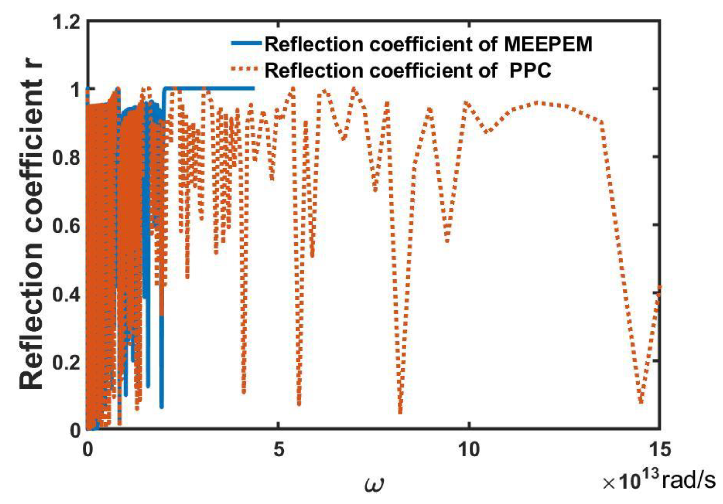
In
Figure 5, the entire reflection spectra of the MEEPEM and of the PPC are represented by the blue solid line and red dashed line, respectively. Here, the PPC is the IPPLN mentioned above.
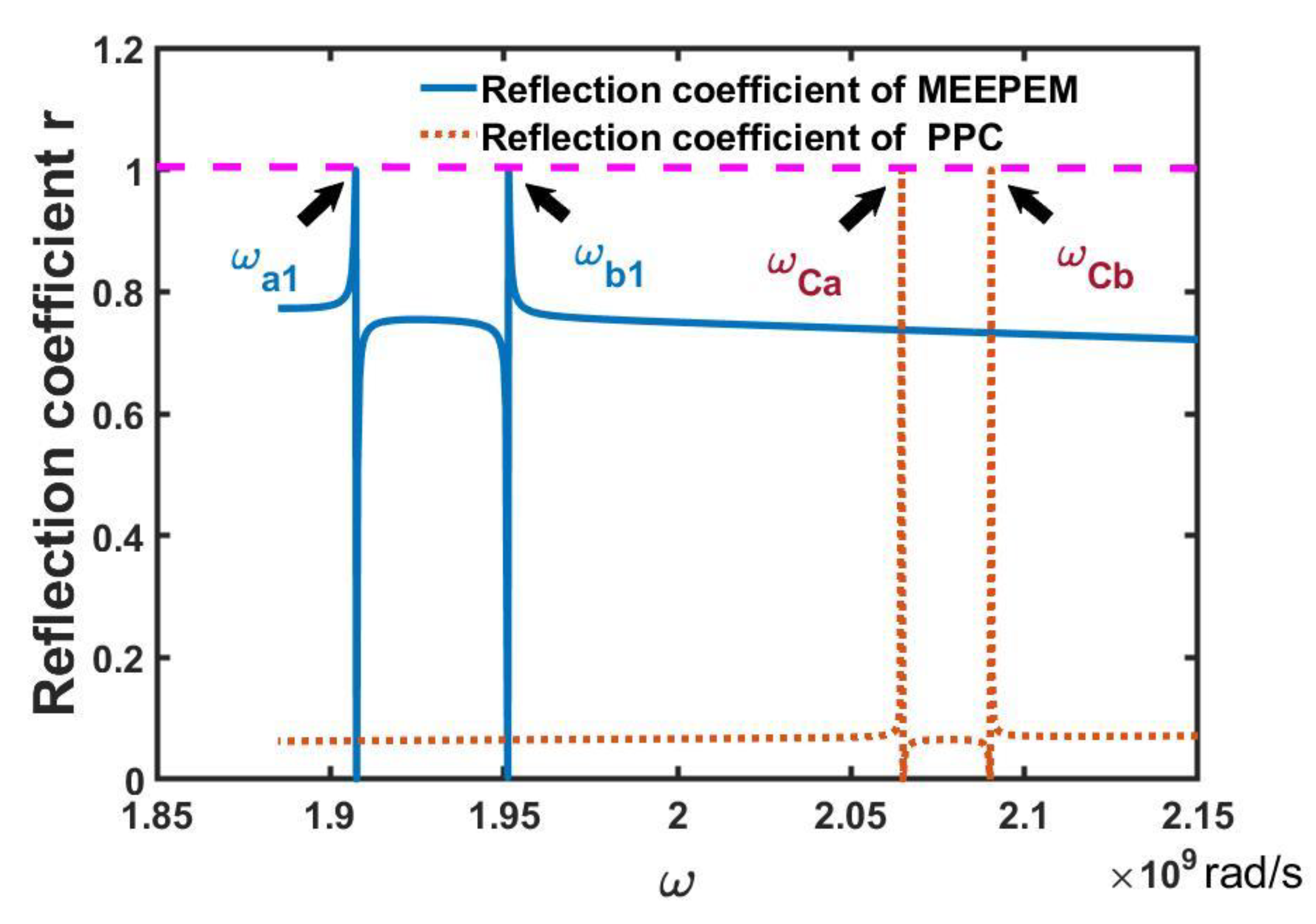
Figure 6 shows the cases in the low frequency region in
Figure 5. In
Figure 6, the reflection spectrum of the MEEPEM shows two reflection peaks and two zero reflection coefficients near the resonance angular frequencies
and
of the first-order multi-field coupling polaritons. Similar cases also exist in the reflection spectrum of the PPC. While the positions of two reflection peaks of PPC are higher than those of MEEPEM due to the resonant angular frequencies of PPC, they are higher than that of MEEPEM. In addition, the intensities of two reflection peaks of PPC are weaker than those of MEEPEM because the coupling of three fields in PPC is weaker than that of MEEPEM. We know the dielectric permittivity is a key factor in the calculation of the reflection coefficients. Therefore, the dielectric anomaly phenomena lead to the changes in the reflection spectra of the MEEPEM and PPC in
Figure 6.
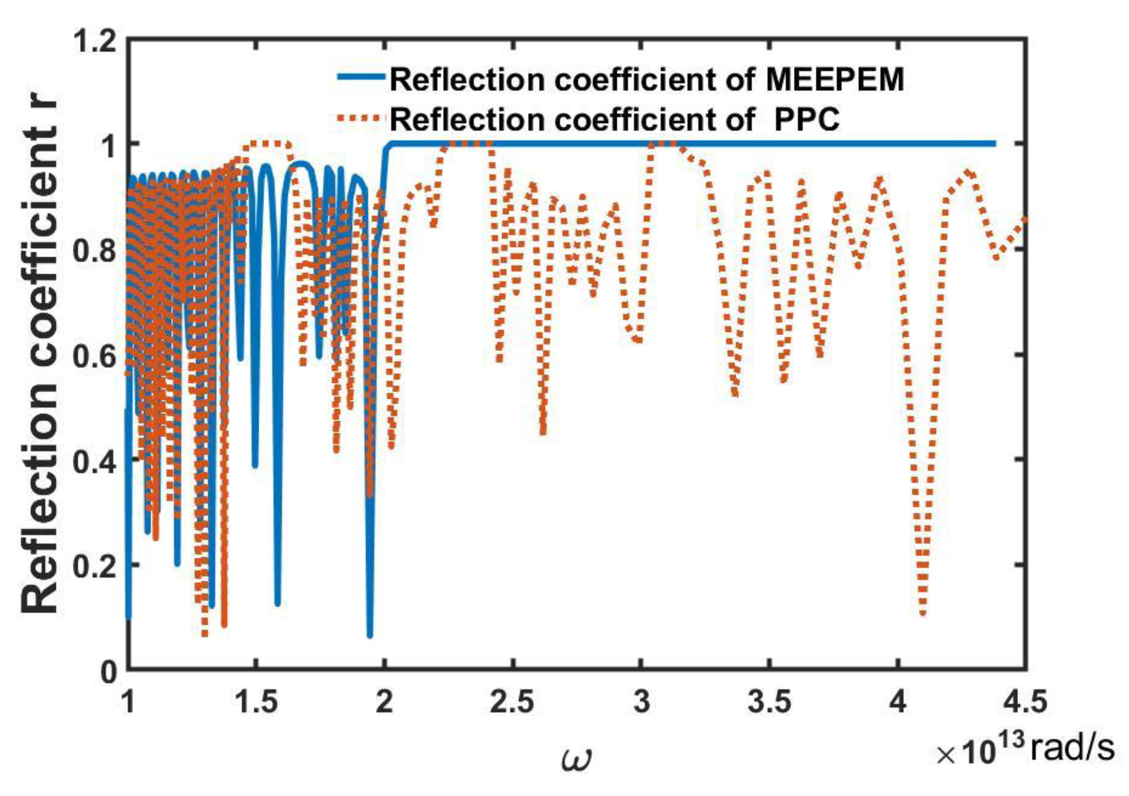
Figure 7 shows the cases in the high frequency region in
Figure 5. As shown in
Figure 7, the reflection spectrum of MEEPEM shows one very wide PBG, and that of PPC shows three PBGs (two of them are in the PBG of MEEPEM). The comparison is made in
Table 1. The frequency position of MEEPEM is higher than that of PPC, and the frequency width of the PBG of the MEEPN is wider than the case of the PPC. The simulation results can be clarified by the variations in impedance
and
in Equation (32), which have a great influence on electromagnetic wave propagation. The impedance depends on the variation in the permittivity. Here, the variations in the permittivity are a result of the coupling between electric, acoustic, and magnetic fields in the MEEPEM. By fixing the values of other parameters in the Equation (32), we have investigated the effect of the dielectric permittivity on the PBGs. The research found the larger the ratio of
to
, the more the widths of the PBGs increase, and the higher the positions the PBGs move to, and vice versa.
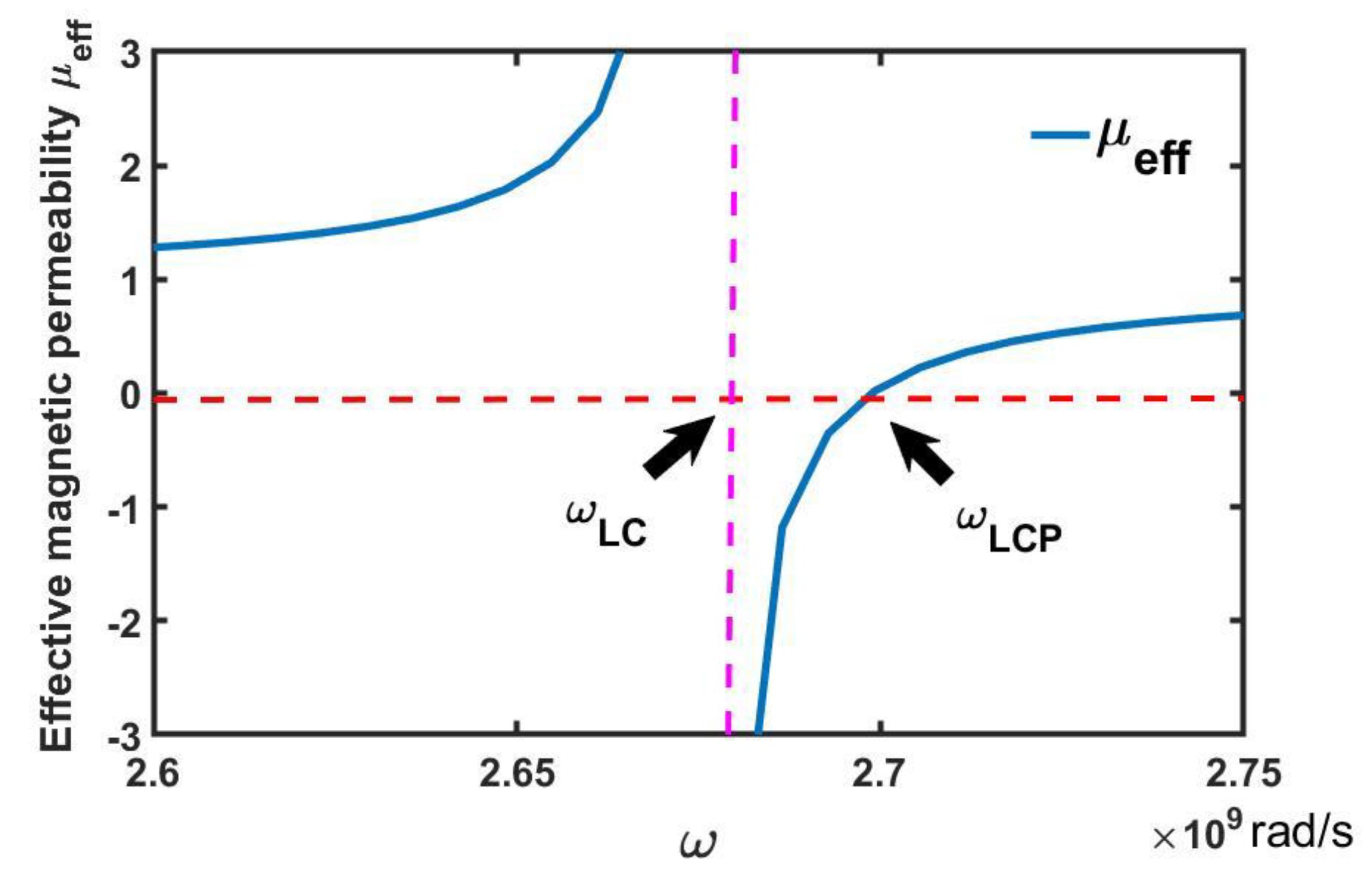
From Equation (33), the real part of the effective magnetic permeability function
of SRR is shown in
Figure 8, which is represented by the blue solid lines; here,
m,
m, and
m. As can be seen in
Figure 8, there is one anomalous peak near the magnetic resonance angular frequency
= 2.68 Grad/s. The effective magnetic permeability
exhibits negative values in the angular frequency gap (
,
), i.e., PBG, in which the propagation of EM waves in MEEPEM will be forbidden, where
= 2.70 Grad/s, which can be obtained by setting
= 0 in Equation (33). Upon inserting
in the expression
−
, we can obtain the width of the PBG. While in the PBG (
,
), the real parts of two dielectric functions
and
also exhibit negative values. That is, both the magnetic permeability and dielectric permittivity of the MEEPEM are negative, and the MEEPEM will become the left-handed metamaterial with negative refraction [
2,
36,
37,
38,
39]. In the MEEPEM, the condition for obtaining a negative refractive index is
< min (
,
), which can be obtained by adjusting the structural parameters of the SRRs in MEEPEM.
4. Conclusions
In summary, we have designed an MEEPEM with a square lattice of the periodic arrays of conducting wires, PPC, and SRRs. We analyzed the mechanism for multi-field coupling in MEEPEM. The magnetic field of the EM wave excites an attractive Ampère force in two identical SRRs sharing a common axis, which periodically compress PPC, and this can create additional electric polarization due to the piezoelectric effect. While the electric field of the EM wave can excite longitudinal superlattice vibration in the PPC, it can also create additional electric polarization. Two additional electric polarizations are coupled to the electric field of the periodic arrays of conducting wires. The coupled electric field is coupled to the EM wave. These interactions result in the coupling between the longitudinal superlattice vibrations, magnetic field, and electric field in the MEEPEM.
We have calculated the dielectric functions, the effective magnetic permeability, and the reflection coefficients of MEEPEM. By using them, we have analyzed the transmission properties of EM waves in the MEEPEM. From the dielectric spectrum, we found the effective plasma frequency of conducting wires splits into two angular frequencies. Near the resonance angular frequencies of multi-field coupling polaritons, there are two dielectric abnormalities. The negative regions of the dielectric spectrum form PBGs. In addition, the dielectric spectrum exhibits four frequency positions of zero refractive indices. According to the reflection spectrum, near the resonance angular frequencies of multi-field coupling polaritons, there are two reflection peaks of both MEEPEM and PPC. The positions and intensities of two reflection peaks of PPC are higher and weaker than those of MEEPEM, respectively. In addition to these, the reflection spectrum of MEEPEM shows one very wide PBG, and that of PPC shows three PBGs (two of them are in the PBG of MEEPEM). The PBG position of MEEPEM is higher that of PPC, and the PBG width of MEEPN is wider than the case of the PPC. The variations in these properties are a result of the coupling between the longitudinal superlattice vibrations, magnetic field, and electric field in the MEEPEM.
The effective magnetic permeability also exhibits one PBG near the magnetic resonance angular frequency. By adjusting the structure parameters of the SRRs in MEEPEM, if PBG of effective magnetic permeability exists in the range of the PBGs of the dielectric function, the MEEPEM will become a left-handed metamaterial with negative refraction.
Furthermore, by modulating the MEEPEM parameters, the MEEPEM can meet the application requirements. These basic theoretical studies provide guidance for the application of MEEPEM in the field of electromagnetic waves, such as the polarizer, the reflector, and wavelength division multiplexing devices.


 ,
, 


