


Abstract
An instance of the framework for cryptographic security enhancement of symmetric-key encryption employing a dedicated error correction encoding is addressed. The main components of the proposal are: (i) a dedicated error correction coding and (ii) the use of a dedicated simulator of the noisy channel. The proposed error correction coding is designed for the binary erasure channel where at most one bit is erased in each codeword byte. The proposed encryption has been evaluated in the traditional scenario where we consider the advantage of an attacker to correctly decide to which of two known messages the given ciphertext corresponds. The evaluation shows that the proposed encryption provides a reduction of the considered attacker’s advantage in comparison with the initial encryption setting. The implementation complexity of the proposed encryption is considered, and it implies a suitable trade-off between increased security and increased implementation complexity.
1. Introduction
The use of coding and noisy channel-based techniques for the security enhancement of a given encryption is an important topic. In particular, this approach could significantly increase the cryptographic security margin of a lightweight encryption scheme. For example, in a number of scenarios, we have to employ a given lightweight encryption technique with a certain security margin but a higher one is required. In such a scenario, enhancing the security of the given encryption appears to be an appropriate approach. On the other hand, this approach also implies an additional overhead complexity.
Motivation. It seems to be an interesting issue to design a security enhancement with a number of parameters that provide control over a desired security enhancement and the required implementation and execution costs of the encryption.
The main motivation for this paper was to address the security enhancement of a given encryption scheme that provides an opportunity for a trade-off between the security margin increase and the required costs. Recently, in [1], a framework for the security enhancement of encryption was proposed, and it is an interesting issue to propose coding techniques suitable for developing a particular setting of the considered framework. Our goal was to design a variant of the encryption from [1], with an instance of their employed noisy-channel simulator and a suitable error correction code for the erasure channel with at most one erasure per codeword byte. The coding should provide a reduction of the decoding complexity as well as a reduction of the required parity bits, for the considered erasure channel, in comparison with the use of LDPC, polar or RS codes. Accordingly, for the considered erasure channel, to avoid these shortcomings, we opted for particular integer block codes (IBCs).
Summary of the Results. This paper proposes a novel coding scheme and its application for the security enhancement of encryption schemes. The enhancement is based on the use of the proposed IBC error correction coding for certain channels with erasures that degrade the ciphertext. From the perspective of the legitimate parties who share a secret key, the degradation appears as a transmission of the ciphertext through a binary erasure channel. On the other hand, from the perspective of an attacker, the degradation appears as a transmission of the ciphertext over a binary deletion channel. The degradation is performed by employing a simulated noisy channel that consists of two subchannels so that an additional flexibility is provided for the selection of the parameters to achieve the desired security and the enhancement cost. The proposed IBC coding has a low complexity and is able to correct one erasure per b-bit of data byte.
Organization of the Paper. The framework for the security enhancement of encryption schemes recently reported in [1] is summarized in Section 2. A dedicated IBC coding algorithm is proposed in Section 3. A novel scheme for the cryptographic security enhancement of an encryption scheme employing the proposed error correction coding and simulated channel that from an attacker’s side appears as a channel with synchronization errors is given in Section 4. The cryptographic security evaluation and implementation issues are considered in Section 5 and Section 6, respectively. Conclusions are given in Section 7, and the proof of a Lemma is given in the Appendix A.
2. Related Work and Background on the Security-Enhanced Encryption Scheme
2.1. Related Work and Our Goals
Improving the security margin or enhancing the security of certain cryptographic primitives employing randomness has been employed in a number of reported designs (initially in [2,3]), as well as in the context of wiretap coding. Following these approaches, two main directions can be identified regarding symmetric-keys encryption techniques. One of the encryption approaches is based on the use of a cryptographic key to control error correction coding algorithms, and it is reported, for example, in [4,5,6,7,8,9,10,11,12,13,14,15]. The other approach is the use of error correction coding and noisy channels for the cryptographic security enhancement of a given encryption scheme: this approach has been reported, for example, in [1,16,17,18,19,20,21,22,23,24]. These security enhancements are based on paradigms of the additive noisy channel or channels with synchronization errors. The encryption scheme where encoding and decoding are controlled by the secret key requires very long secret keys because the error correction coding scheme should be secret. In the class of encryption schemes where the error correction coding and noisy channel paradigms are employed for the security enhancement of a given encryption scheme, the required secret keys are much smaller because in this setting, the coding scheme does not need to be secret.
We point out the following illustrative designs of encryption techniques based on a secret coding scheme. One of the first results in this direction was reported in [15], where an approach to design a private-key cryptosystem called RN was proposed which allowed the use of very simple codes. The encryption was performed by employing the matrix , where S is a random nonsingular invertible matrix, G is a generator matrix of an block code, and P is permutation matrix. The basic ciphertext was degraded by an error vector of length n, whose average Hamming weight was about and selected randomly from a syndrome error table. The restricted set of error patterns implied a vulnerability against a chosen plaintext attack because the security depended on a Hamming weight and the number of perturbation vectors, and demanded long keys and a large syndrome error table for a desirable security. In [10], a variant of an RN cryptosystem using a quasi-cyclic low-density parity-check (QC-LDPC) code was proposed in order to offer a high security, low encoding complexity, and small key size. A stream ciphering method based on the linear feedback shift register (LFSR) was incorporated to generate random error vectors, providing a large number of vectors with good cryptographic properties. The design included a method to vary the encryption matrix and the intentional error vector with each message block. A nonlinear RN-like symmetric-key encryption scheme was reported in [12], where the design employed QC-LDPC lattice codes. QC-LDPC codes have also been employed for developing an encryption-based coding as follows. An encryption approach based on QC-LDPC codes was reported in [4], where the absence of permutation and scrambling matrices reduced the key size required compared with similar code-based cryptosystems. In [5], a scheme was proposed which randomly inserted and deleted bits in the codeword of a QC-LDPC code. It was shown that the key size was smaller than other code-based cryptosystems based on permutation and scrambling matrices. The positions of the inserted and deleted bits were determined using a secret key.
A number of the reported designs are based on polar codes (see, for example, [25,26]). In [13], an efficient secret-key cryptosystem based on polar codes over the binary erasure channel was proposed, where the generator matrix of the polar codes was hidden from an attacker. In [7], a novel approach was employed to keep the generator matrix of a polar code secret from an active attacker and a polar encoding/encryption algorithm based on the hidden generator matrix introduced, so that an attacker could not decode the eavesdropped data without the knowledge of the secret key shared between the legitimate parties. An encryption scheme [8] based on a polar code for the physical layer encryption (PLE) with a short key length was reported in [8] together with its security evaluation. In [9], an encryption algorithm based on polar codes and chaotic sequences allocated to the frozen bits of polar codes was reported. Since the frozen bits were not known to the eavesdroppers, it was difficult to perform decoding. The reported results in [14] showed that using polar codes in conjunction with the learning with errors (LWE)-problem-based encryption yielded several advantages. A survey on the development of polar-code-based encryption approaches is reported in [11] including a discussion on the reduction of the key size in these schemes.
An encryption approach based on the use of a traditional linear block code and a simulator of a channel with synchronization errors was proposed in [6]. The employed simulator of the noisy channel performed bits flipping and deletion and random bits insertion according to the outputs of secret-key-controlled LFSRs, but it was shown in [27] that this approach is vulnerable.
The use of the noisy channel approach for the security enhancement of a given encryption has been discussed from a number of perspectives and some of them are discussed below.
The secrecy enhancement of the Data Encryption Standard (DES) block cipher working in a cipher feedback model (CFB) when an adjustable noise is introduced into the encrypted data, was considered in [16]. The main goal was to generate a degraded wiretap channel in the application layer over which a Wyner-type secrecy encoding was employed. In [28], a study of the statistical properties of the errors in certain block-ciphered cryptosystems was reported. These statistics could be employed for the design of block-ciphered cryptosystems, where errors were intentionally introduced to enhance the security against passive eavesdroppers. On the other hand, the experimental results reported in [29] showed that the errors in ciphertext did not guarantee a security increase of the modified data encryption standard (M-DES), where a key-based coded permutation cipher paradigm was employed to improve the security of the transmission in the wireless channel.
In the following, we discuss the following two paradigms for the security enhancement: (i) encode → encrypt → degrade paradigm employed for stream ciphers enhancement in [17,19,21,23,24]; (ii) encrypt → encode → degrade paradigm reported in [1,18,20,22].
Certain provably secure symmetric encryption techniques based on the hard learning problems were reported in [23,24], where the Learning Parity in Noise (LPN) and the LWE problems were employed for the design of provably secure encryption implied by strong hardness guarantees. These approaches employed additive noise and error correction coding to enhance the security of simple keystream generators (such as linear feedback shift registers). In [17], the security enhancement of given stream cipher was proposed employing a concatenation of a simulated channel with bit insertions and a physical binary symmetric channel (BSC). In a simplified setting where the encryption was performed using a linear finite state machine, it was shown that the security enhancement corresponds the hardness of the underlying LPN problem. A general model of a security-enhanced encryption scheme that followed the encode → encrypt → degrade paradigm was considered from the information-theoretic and computational-complexity points of view in [19,21], respectively.
In [22], the security enhancement of a DES-based block cipher, operating in a cipher feedback (CFB) mode, employing an RS code and assuming a BSC noisy channel was proposed. Additionally, the required number of plaintext–ciphertext pairs for mounting a known plaintext attack, in the presence of noise in the ciphertexts, as well as the trade-off between security enhancement and performance degradation, were considered. In [1,18,20], schemes are proposed for a security-enhanced encryption scheme based on simulators of certain channels with synchronization errors and LDPC or polar error correction coding. An approach for the security enhancement employing a simulated noisy channel with bits insertion was proposed in [18] and the enhancement was evaluated by an information-theoretic approach. Two approaches for the security enhancement of encryption algorithms employing simulated noisy binary channels that consisted of the erasure channels for the legitimate receivers and as the binary deletion channels for an attacker were proposed in [1,20]. The security enhancement was considered by employing a traditional game-based evaluation approach to show the reduction of the attacker advantage.
This paper addresses the encryption approach that involves nonsecret error correction coding. In the considered class, beside the coding, the noisy channel paradigm is employed to achieve the desired security enhancement of the encryption scheme. The main components of these schemes are: (i) the initial encryption that is the subject of the enhancement; (ii) the employed error correction codding; and (iii) the employed paradigm of the noisy channel. The coding schemes were dedicated to the involved noisy channel. The following noisy channel models were mainly considered: the additive noisy channel, erasure channels, channels with synchronization errors, and channels with additive and synchronization errors. The commonly considered additive noisy channel was the BSC, and regarding the channels with synchronization errors, the deletion channels and the insertion channels were considered.
Regarding the error correction coding issues, in this paper, we focused on the reconstruction of a codeword containing one erasure per data byte. The standard way to solve this problem would be to use powerful error correction codes, such as LDPC, polar, or RS codes. However, one such solution would be impractical for two reasons. The first one is that all the mentioned codes have complex decoding algorithms. In particular, it is known that LDPC and polar codes have a log-linear decoding complexity [30,31], while RS codes can be decoded in log-linear time only for certain code lengths [32]. So, whether implemented in hardware or software, these codes would use a large number of operations, even to decode short codewords. The second reason why the mentioned codes would be impractical lies in their redundancy. If, for example, LDPC or polar codes were to be used to reconstruct the codeword, the number of check bits would have to be close to the number of data bits. On the other hand, if RS codes were used, the number of check bits would be significantly smaller, but not negligible (e.g., for data lengths greater than 500 bits, it would be necessary to use more than 100 check bits). Due to these shortcomings, in this paper, we considered IBCs that were previously used to correct burst and/or random errors within the codeword [33,34,35,36].
Our goal is to design a variant of the encryption [1] with an instance of their employed noisy channel simulator and a suitable error correction code for the erasure channel with at most one erasure per codeword byte. Following the results reported in the discussed papers, the main goal of this paper was to propose an approach for a security-enhanced encryption where: (i) the initial encryption scheme belongs to the class of lightweight block ciphers or certain stream ciphers; (ii) a novel block error correction code for the erasure channel is employed; and (iii) a dedicated simulator of the noisy channel suitable for the developed error correction code is used. The considered channel is a variant of the one reported in [1], and the use of the developed error correction code appears more suitable over this channel in comparison with LDPC, polar, or RS codes.
2.2. Main Background
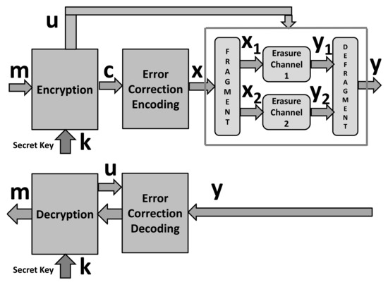
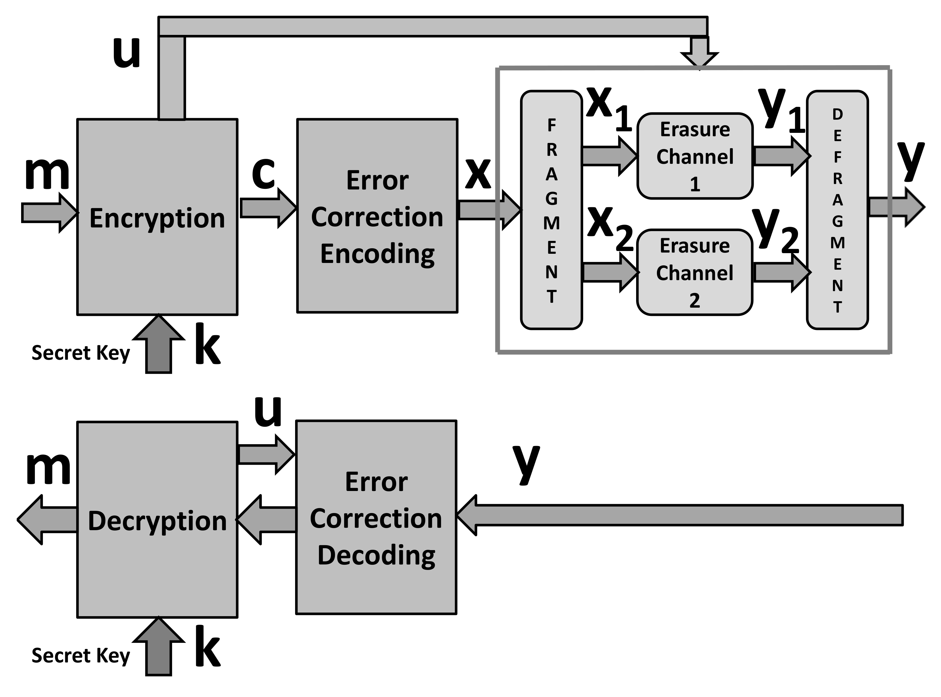
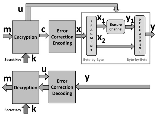
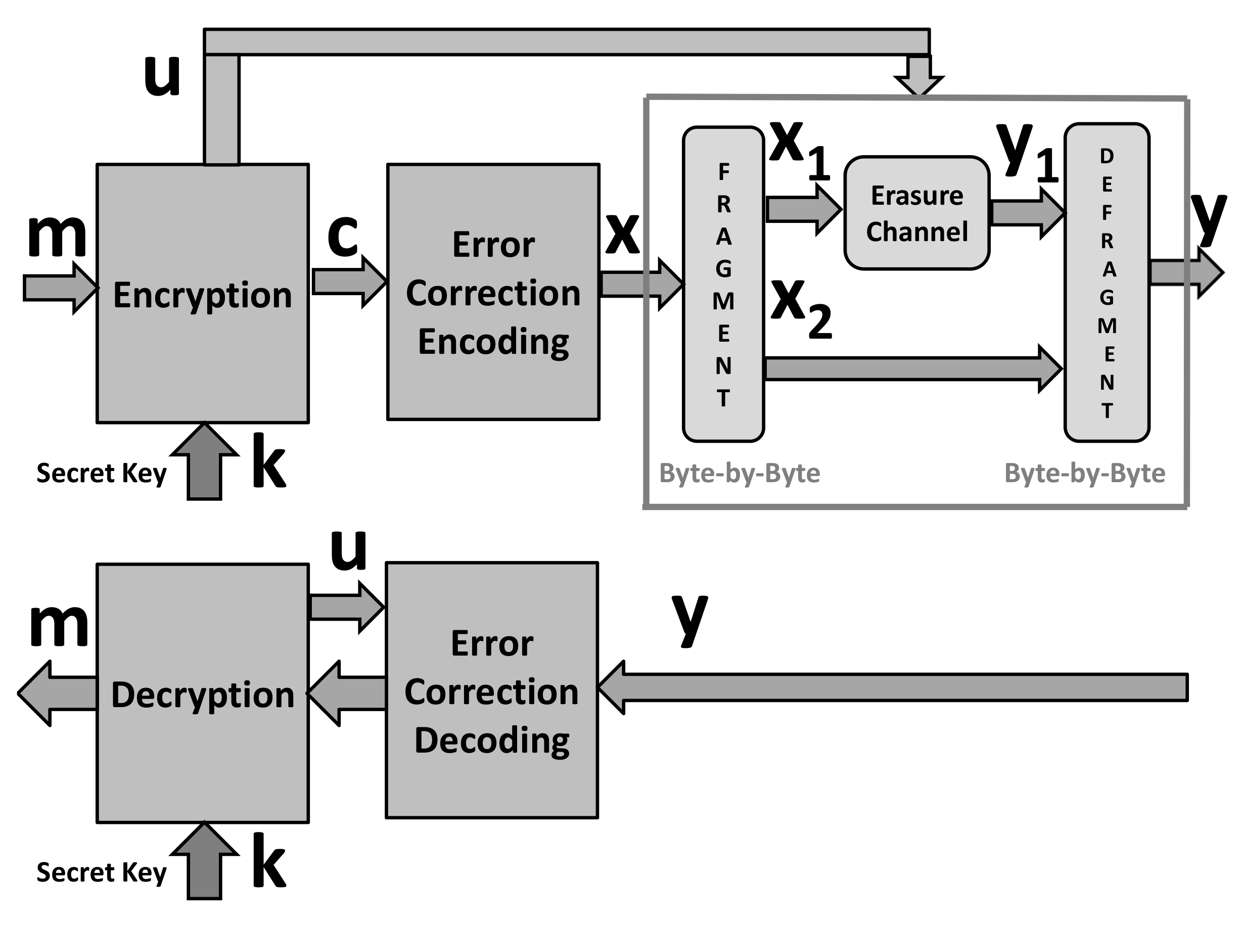
This section shows the cryptographic security enhancement of an encryption scheme employing error correction coding and the simulator of a channel with synchronization errors reported in [1] and displayed in Figure 1.
Figure 1.
Generic framework for security-enhanced encryption scheme [1].
As in [1], we use the following notation. The message, a data vector subject to encryption is denoted by and we assume that it is a realization of the binary vector variable . The encrypted form of is denoted by and we assume that it is a realization of the binary vector variable ,
where denotes the encryption mapping controlled by the secret key . The vector denotes the encoded version of employing an error correction encoding , which performs the mapping , ,
and is a realization of a random binary variable .
We consider a channel in which the input sequence is divided into subsequences and these subsequences are transmitted through independent i.i.d. binary deletion channels, and the arrived bits after the deletion channels are combined, preserving their order in the original input sequence. Consequently, the resulting channel is an i.i.d. binary deletion channel with parameters which depend on the parameters of the considered subchannels.
The simulator of the considered channel is controlled by a vector generated by the encryption algorithm which is considered as a realization of a binary random vector .
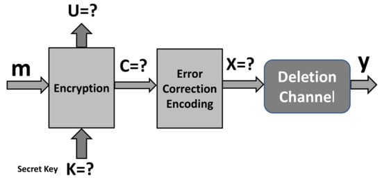
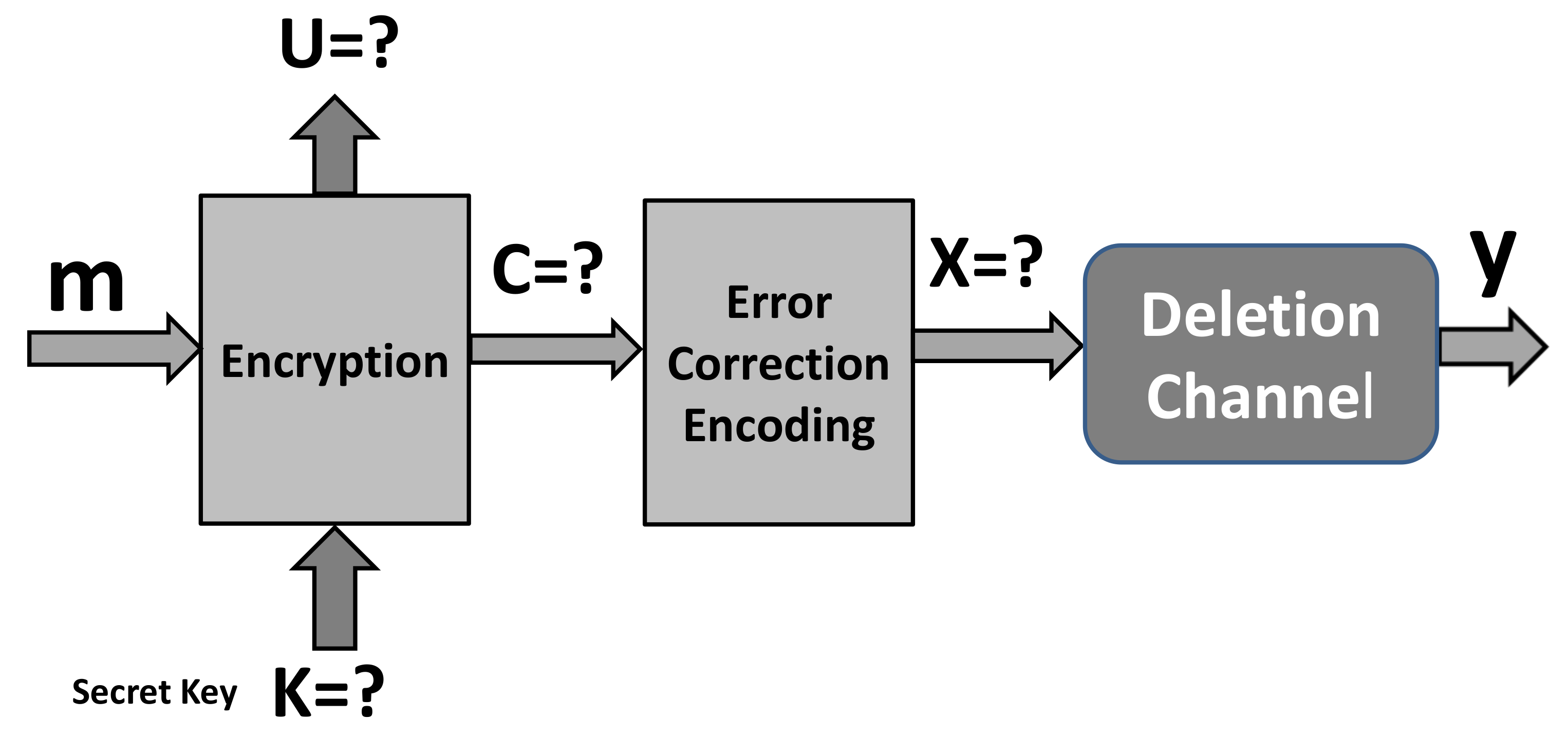
An attacker on the encryption scheme from Figure 1 faces the problem of the cryptanalysis of the known plaintext attack displayed in Figure 2.
Figure 2.
Model of encryption for cryptanalysis at the attacker’s side under known plaintext attack [1].
Note that the legitimate parties face the problem of decoding after a binary erasure channel, but the attacker faces the much harder problem of dealing with decoding after a deletion channel. The knowledge of attackers is limited to the following. Each channel input bit is transmitted through Channel 1 with probability , and through Channel 2 with probability , independently of each other. If transmitted through Channel 1, a bit is deleted with the probability , and if transmitted through Channel 2, a bit is deleted with the probability . The attacker does not know the specific realization of the “individual channel selection events”, i.e., they do not know which specific subchannel a bit is transmitted through, and which specific subchannel each output symbol is received from.
3. Integer Codes Correcting One Erasure per Data Byte
This section proposes an error correction coding and addresses the following three issues: (i) the considered scenario of the codewords degradation; (ii) the construction of the code; and (iii) illustrative examples.
3.1. Scenario of Employment
First, we give two definitions that are necessary for understanding the concept of integer erasure correcting codes.
Definition 1.
An error is called a 1/k-erasure if each of the k data bytes is affected by one erasure.
Definition 2.
Let = {0, 1, …, 2 − 2} be the ring of integers modulo 2 − 1 and let be the integer representation of a b-bit byte, where {0, 1} and 1 ≤ i ≤ k. Then, the code C (b, k, c), defined as
is a (kb + b, kb) integer erasure correcting code, where c = (1, C, C, …, C) is the coefficient vector and B is an integer.
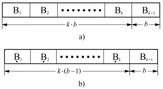
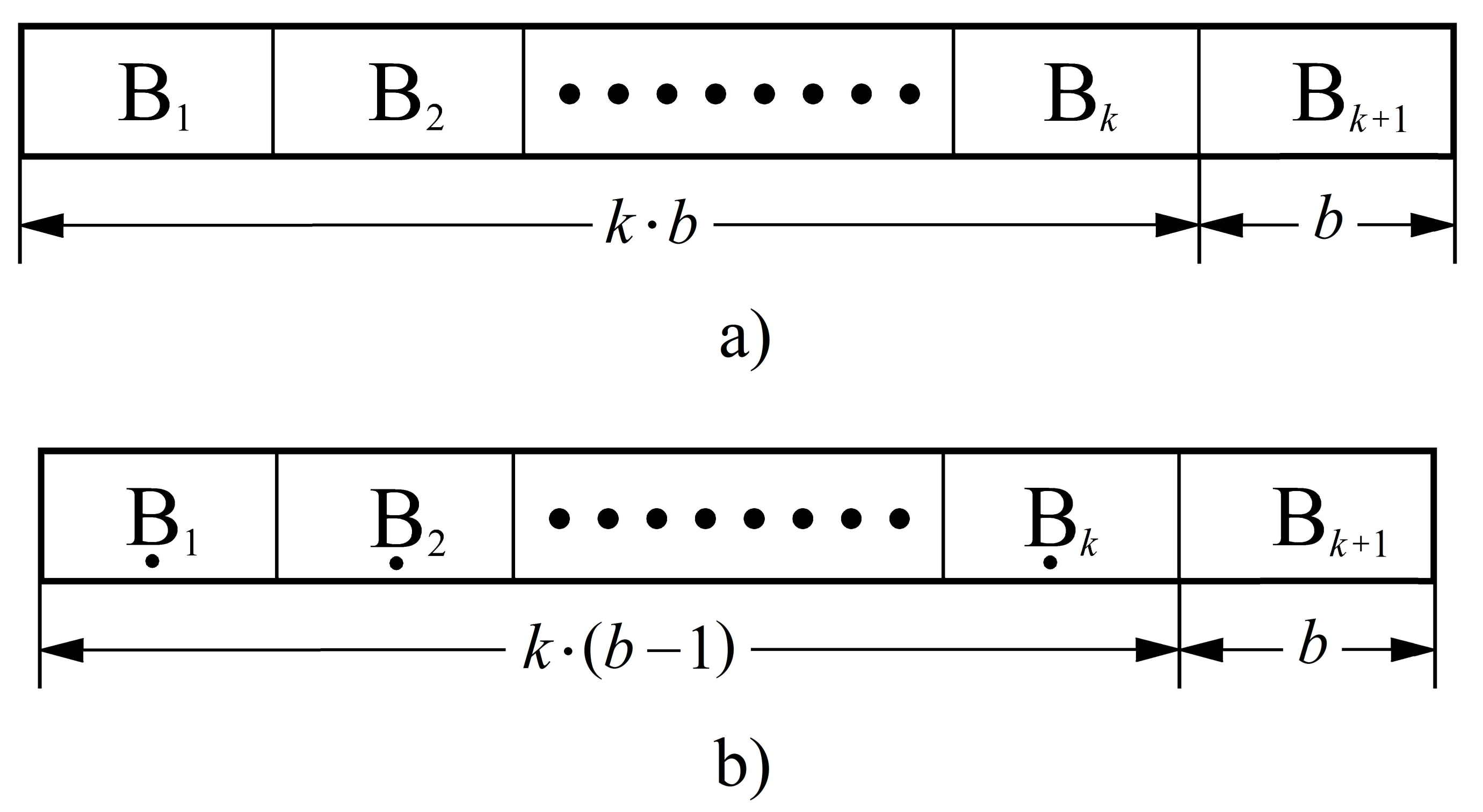
We assume the following: (i) in a simulated noisy channel, the codeword is degraded by deletion of one bit from each b-bit byte except the last one (so, instead of bits, the sent codeword will have bits (Figure 3)) and (ii) the degradation is controlled by a secret information shared between sender and receiver.
Figure 3.
The codeword structure after: (a) the encoding process and (b) the deleting process.
When it receives a shortened codeword, the receiver inserts k zeros at the deleted bit positions. This means that the integer value of each received b-bit data byte either remains unchanged or is reduced by 2, where 0 ≤ r ≤ b − 1.
3.2. Code Construction
Definition 3.
Let V = {0, 1} and P = {1, 2, … , b}. Then, the vectors representing the values and positions of the deleted bits within each of the k data bytes are, respectively, defined by v = (vv, …, v) and p = (pp, …, p)
Definition 4.
Let x = (B, B, …, B, B) be the original codeword and let y = (B, B, …, B, B) be the received codeword in which one bit (of the known position) within each of the k data bytes is replaced by a binary zero. Then, the syndrome S of the received codeword is defined as
where e ∈ {0, 2, 2, 2, …, 2}.
From the previous definition, it is clear that the original codeword is instantly reconstructed if S = 0. Hence, it is reasonable to take the position that the received codeword is invalid only if S ≠ 0. This leads us to the following definition.
Definition 5.
The set of syndromes corresponding to 1/k-erasures is defined as
where
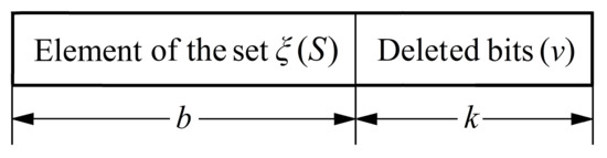
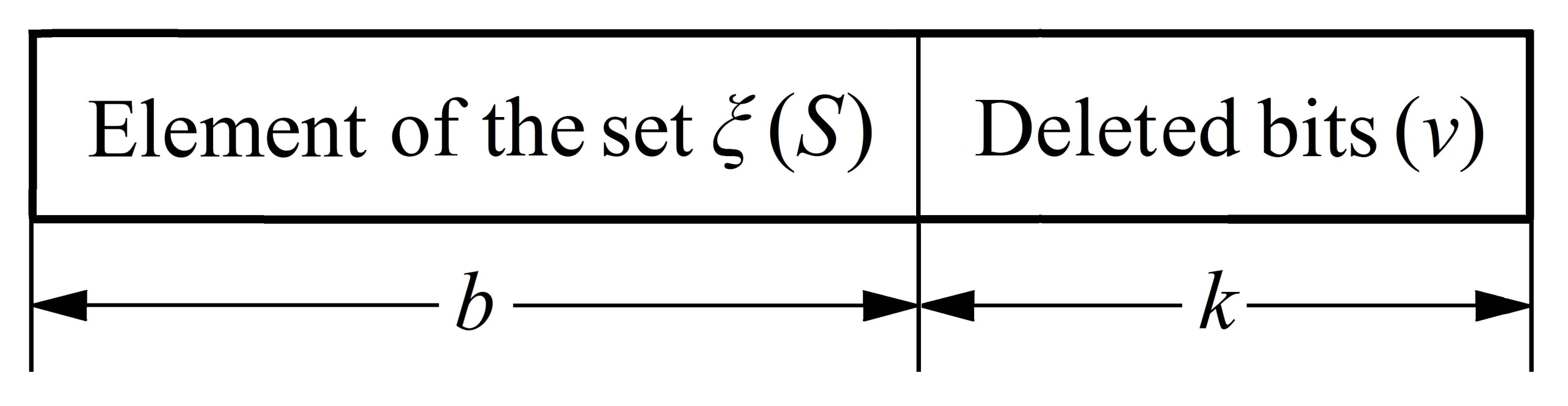
Since the receiver does not know the value of the vector v, it must obtain it through the syndrome S. The simplest way to do this is to use the syndrome table (ST) whose entries are sets of pairs (S, v) (Figure 4). Such a table can be easily generated if the values of the vectors c and p are known.
Figure 4.
Bit-width of one ST entry.
However, what we do not know is the size of the ST, i.e., how many (S, v) pairs there are. The answer to this is given by the following theorem.
Theorem 1.
The codes defined by (1) can correct a 1/k-erasure if for each vector p = (pp, …, p) , there exists a coefficient vector c = (1, C, C, …, C) , such that
where | ξ | is the cardinality of ξ.
Proof.
The integer code C(b, k, c) is said to be a correctable 1/k-erasure if all its syndromes are nonzero and mutually different. This condition will be satisfied if for each vector p, there exists a coefficient vector c such that
Only in that case will the set ξhave
nonzero elements.
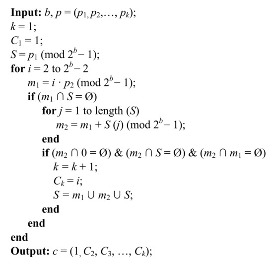
So, the necessary and sufficient condition for the construction of the proposed codes is that for each vector p, there is at least one vector c. On the other hand, from Definition 3 we see that there are b possible values of the vector p. Both these facts lead to the conclusion that the vector c cannot be generated without using a computer (Figure 5). Once its value is known, the receiver will generate the ST after which communication can start. □
Figure 5.
The pseudocode for generating the vector c.
3.3. The Pseudocodes and Illustrative Examples
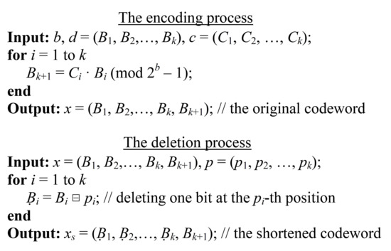
Pseudocodes of the encoding, codeword degradation, and decoding procedures at the sender and receiver.
Figure 6 displays the pseudocodes for the encoding and deletion processes. The transmitter forms a codeword and then degrades it by deleting one bit from each b-bit byte except the last one (in the considered illustrative case).
Figure 6.
The pseudocode for the encoding and deletion processes.
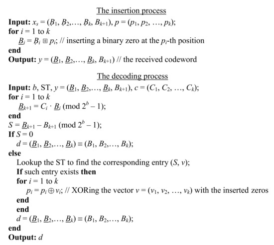
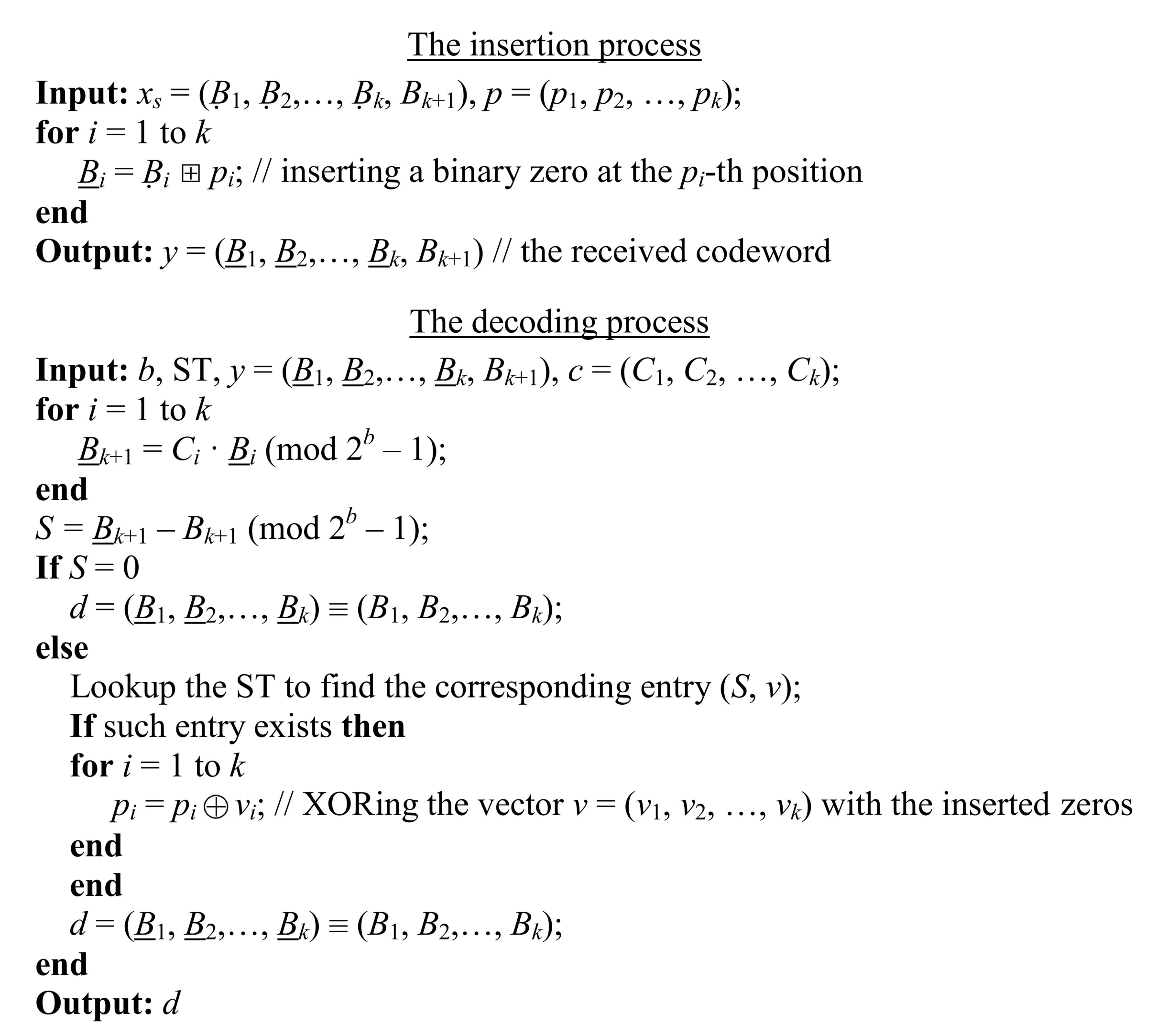
Figure 7 displays the pseudocodes for the insertion and decoding processes. The receiver first inserts binary zeros at the deleted positions and then calculates the value of the syndrome S. If , the receiver looks up the ST to get the value of the vector v. After that, it modifies the initially reconstructed codeword by XORing the vector v with the inserted binary zeros.
Figure 7.
The pseudocode for the insertion + decoding processes.
Example 1.
Suppose that b = 5 and p = (1, 2, 3, 4). In that case, both the sender and receiver generate the vector c = (1, 3, 5, 7), while the receiver additionally generates the ST (Table 1). After that, the communication starts with the sender generating the check-byte B. If, for example, the data word has 20 bits, say d = (B, B, B, B) = (01010, 11010, 11100, 01110) = (10, 26, 28, 14), the value of the check-byte is
Table 1.
The ST for the (25, 20) integer 4-erasure correcting code when p = (1, 2, 3, 4).
As a result, the original codeword has 25 bits, x = (B, B, B, B, B) = (01010, 11010, 11100, 01110, 10000) = (10, 26, 28, 14, 16). In the next step, the sender deletes the first bit from the first byte, the second bit from the second byte, the third bit from the third byte and the fourth bit from the fourth byte. This means that the sent codeword has 20 bits, x = (B, B, B, B, B) = (1010, 1010, 1100, 0110, 10000).
When it receives such a codeword, the receiver first inserts binary zeros at the deleted positions, y = (01010, 10010, 11000, 01100, 10000) = (10, 18, 24, 12, 16). After that, it calculates the value of the syndrome S
Since S ≠ 0, the receiver looks up the ST to get the value of the vector v. When this procedure is completed, the receiver modifies the initially reconstructed codeword by XORing the vector v = (0, 1, 1, 1) with the inserted binary zeros. As a result, the codeword has the form y = x = (B, B, B, B, B) = (01010, 11010, 11100, 01110, 10000).
Example 2.
Suppose that b = 5 and p = (2, 4, 3, 2). As in the previous example, the sender and receiver generate the vector c = (1, 2, 4, 5), while the receiver additionally generates the ST (Table 2). If the same 20 bits of data are sent again, d = (B, B, B, B) = (01010, 11010, 11100, 01110) = (10, 26, 28, 14), the sender calculates the check-byte
after which the codeword having 25 bits is generated, x = (B, B, B, B, B) = (01010, 11010, 11100, 01110, 11011) = (10, 26, 28, 14, 27). In the next step, the sender deletes the second bit from the first byte, the fourth bit from the second byte, the third bit from the third byte, and the second bit from the fourth byte. As a result, the sent codeword has 20 bits, x = (B, B, B, B, B) = (0010, 1100, 1100, 0110, 11011).
Table 2.
The ST for the (25, 20) integer 4-erasure correcting code when p = (2, 4, 3, 2).
When such a codeword arrives, the receiver first inserts binary zeros at the deleted positions, y = (00010, 11000, 11000, 00110, 11011) = (2, 24, 24, 6, 27), and then calculates the value of the syndrome S
Since S ≠ 0, the receiver looks up the ST to obtain the value of the vector v. After that, it modifies the initially reconstructed codeword by XORing the vector v = (1, 1, 1, 1) with the inserted binary zeros. As a result, the codeword has the form y = x = (B, B, B, B, B) = (01010, 11010, 11100, 01110, 10000).
3.4. Evaluation Issues
The only unknown regarding the proposed codes is the dimension of the vector c. The reason is that it is determined by means of a computer, and hence, it is not possible to know its dimension in advance. However, the results of all our experiments showed that the equality k = b − 1 holds regardless of the value of the vector p. One confirmation of this is the parameters of the codes from Examples 1 and 2. Having this in mind, we can draw the following statements regarding the proposed codes: (i) the proposed codes use integer arithmetic, which is supported by all processors. Owing to this, they have the potential to run very fast in software; (ii) the proposed codes can be decoded in linear time, which makes them computationally more efficient than the standard ones; (iii) the proposed codes have much lower redundancy than the standard ones. For example, to reconstruct a data word having 20 bits (Examples 1 and 2), RS codes would have to use at least 20 check-bits. Unlike them, the proposed codes require only five check bits; and (iv) the proposed codes are not suitable for protecting long data streams. The reason is the size of the ST, which grows exponentially with the number of data bytes (the ST has 2 – 1 entries, where each entry is (k + b)-bits wide).
4. Security-Enhanced Encryption Scheme
In this section, we propose a particular instance of the framework given in Section 2. In particular we propose designs for the following two parts of the generic framework: (i) encryption scheme and (ii) simulated noisy channel. Figure 8 displays the proposed instance of the generic framework suitable for the use of the coding scheme proposed in Section 3.
Figure 8.
Proposed security enhanced encryption scheme.
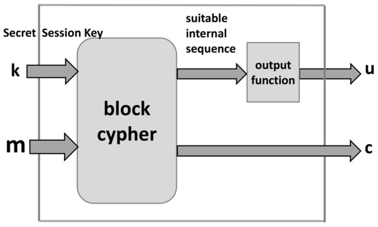
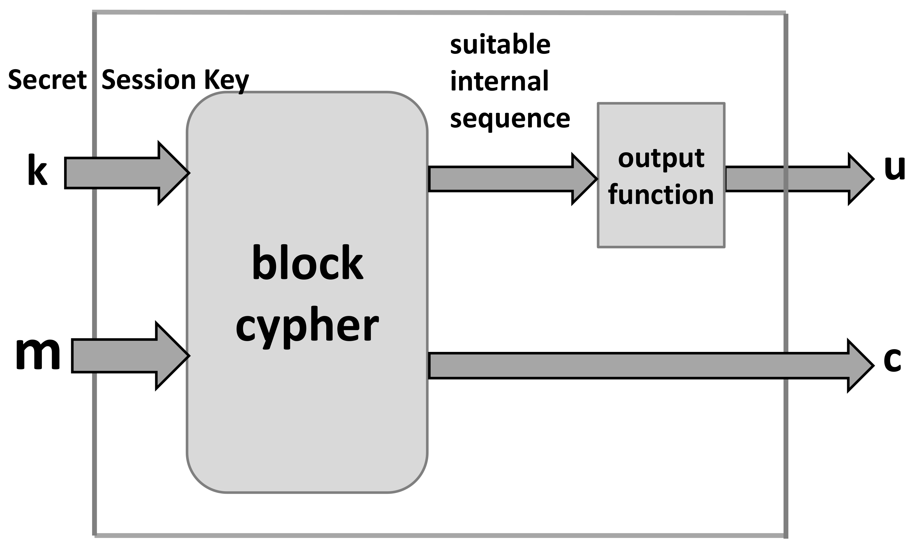
Encryption.Figure 9 displays a model of the encryption box based on a block cipher: The inputs are the session secret key and the plaintext message , where and are binary vectors. The outputs are the binary vectors of ciphertext and the control sequence for the simulated noisy channel.
Figure 9.
Model of encryption based on a block cipher.
Note that the above scheme provides all vectors (sequences) required by the encryption box in Figure 3, and in particular the binary vector that controls the simulation of the noisy channel.
Coding. The error correction code proposed in Section 3 is employed.
Simulated Noisy Channel. The simulated noisy channel box takes the sequence as input and performs its mapping block-by-block in order to obtain the sequences required for the simulated noisy channel composed of two binary channels—one error free and the other a binary erasure channel. Let denotes a b-bit segment of , and let the functions , , perform the following mappings:
generating the following:
and we assume that the probability that takes the value 1 is equal to .
Let be the codeword byte after the encoding box, and denotes the codeword byte after the simulated noisy channel according to the following algorithm.
Algorithm of Simulated Noisy Channel
- Input: b-bit byte , of the codeword and the parameter and the vector . If the considered byte is the check-byte, preset .
- if : do i = 1, b
- -
- = ? if = i
- -
- otherwise
- if : do i = 1, b
- -
- Output: b-bit byte
Note that, for the legitimate receiver, appears as the codeword after the binary erasure channel. On the other hand, because the attacker does not know the sequence , appears as the codeword after the binary deletion channel as displayed in Figure 2.
The proposed approach for the security enhancement is a general one and could be directly employed for the block cipher encryption techniques assuming block-by-block processing, as well as in a number of stream ciphers where the ciphertext segments subject to encoding are self-contained.
5. Security Evaluation of the Enhanced Encryption
5.1. Security Notation
We employed a traditional approach for analyzing the cryptographic security based on the following two issues: (i) a description of what a “break” of the scheme means, and (ii) a specification of the assumed power of the adversary. A cryptographic scheme is considered as a secure one in a computational sense, if for every probabilistic polynomial-time adversary performing an attack of some specified type, and for every polynomial , there exists an integer N such that the probability that succeeds (where success of the attack is also well-defined) is less than for every . Accordingly, the following two definitions specify a security evaluation scenario and a security statement.
Definition 6
([37]). The adversarial indistinguishability experiment consists of the following steps:
- 1.
- The adversary chooses a pair of messages of the same length n and passes them on to the encryption system for encrypting.
- 2.
- A bit is chosen uniformly at random, and only one of the two messages , precisely , is encrypted into ciphertext and returned to .
- 3.
- Upon observing , and without knowledge of b, the adversary outputs a bit .
- 4.
- The experiment output is defined to be 1 if , and 0 otherwise; if the experiment output is 1, denoted shortly as the event , we say that has succeeded.
Definition 7
([37]). An encryption scheme provides indistinguishable encryptions in the presence of an eavesdropper, if for all probabilistic polynomial-time adversaries
where is a negligibly small function.
Definitions 6 and 7 are more precisely discussed in [37]. Please note that the employed encoding is a deterministic algorithm such that it does not affect the security of the entire encryption scheme. Assuming that the employed decoding algorithm provides error-free decoding, it also neither increase nor decrease the security of the encryption. An increase of the security margin is the consequence of the employed noisy channel and the encoding just provides a correction of the errors on the side of the legitimate receiver.
5.2. Evaluation of the Security Gain
We considered the encryption/decryption scheme proposed in Section 4, which is a security-enhanced scheme of a certain basic one. Our goal was to estimate the advantage of in the indistinguishability game specified by Definition 6 when , where is a particular realization of , assuming that the advantage of is known when and are two chosen realizations of and the corresponding realization of is given, i.e., the advantage of is known for the basic (security nonenhanced) scheme.
Lemma 1
([1]). Let the mapping of into be such that equals the advantage of the adversary (specified by Definition 7) to win the indistinguishability game (specified by Definition 6). Under these assumptions,
Definition 1 implies that the security of an encryption scheme increases as the difference on the adversary advantage from decreases: the factor shows the reduction rate of the advantage, and so we call it the advantage reduction factor.
Theorem 2.
Let the basic encryption mapping of into , be such that equals the advantage of the adversary (specified by Definition 7) to win the indistinguishability game (specified by Definition 1). Consequently, the advantage of the adversary , in the security-enhanced scheme specified in Section 4 is:
Proof.
In the considered statistical model, we assume the following. Let X and Y be discrete random variables, which correspond to the input and output, respectively, of a communication channel. Let the possible realizations of X and Y be x, and y, respectively, and let a decision rule on X when Y is given be considered as the identification of a realization x when y is given; we denote by the probability of the identification (classification) error assuming a classification in one out of v categories. The equivocation, that is the conditional entropy represents the average amount of information lost on X when Y is given. According to [38] or [39], for example, we have the following general upper bound on the equivocation:
where is the binary entropy function and , and the conditional entropy is defined as
where
and denotes the probability of the considered event.
Recall that
where
and the mutual information is upper-bounded by the capacity of the considered communication channel as follows:
Consequently, in the considered evaluation scenario, (8) can be rewritten as
where is the capacity of the employed channel from the attacker’s point of view. According to Lemma 1,
and we obtain
On the other hand, according to Theorem 1 from [40] we have
where is the deletion rate in . Employing the fact that the capacity of a deletion channel is upper-bounded by the capacity of an erasure channel assuming the same deletion and erasure rates and that the capacity of the corresponding erasure channel is equal to , we have
A substitution of (18) into the statement of Lemma 1 yields the proof. □
Lemma 1 shows that the encryption mapping enhances the security because the probability that wins the game becomes closer to , which corresponds to random guessing, by the factor , and Theorem 2 shows that the upper bound on is . Accordingly, Table 3 and Table 4 provide numerical illustrations of the upper bound on (18), which determines the reduction of the advantage of .
Table 3.
A numerical illustration of the advantage reduction factor upper bound (18), which shows a minimum reduction of the advantage of ) as a function of the simulated noisy channel parameter and the code parameters b and k.
Table 4.
A numerical illustration of the advantage reduction factor upper bound (18), which shows a minimum reduction of the advantage of ) as a function of the simulated noisy channel parameter and the code parameters b and k.
In particular, note the following. Definition 7 shows that in the source encryption scheme, we face a leakage of information on the message that is the subject of the encryption, and accordingly at the input of the encoding algorithm, we could detect certain information about the message. On the other hand, as Theorem 2 shows, this information is reduced because the channel outputs a degraded version of the encoded ciphertext to an attacker.
6. Implementation Complexity of the Components for Enhancement
6.1. Time Complexity of the Encoding and Decoding Procedures
Informally, the encoding/decoding procedures of the proposed codes are essentially the same as those from [33,34,35,36]. This means that they have a linear time complexity. To confirm this, we can analyze the operations performed by the encoder and decoder. First, let us focus on the encoder. From (1), we see that it performs two types of operations: multiplication modulo 2 − 1, which requires b bit operations, and addition modulo 2 − 1, which takes b bit operations. To generate the check-byte B, the encoder must perform k multiplications and k − 1 additions. Since the codeword has n = (k + 1)·b bits, from the expression O(b·k + b·k − b) ≈ O(b·k) ≈ O(b·n) = b·O(n) = const.·O(n,) we easily conclude that the encoding procedure has a linear time complexity. When it comes to the decoder, from (2), we see that it performs one operation more than the encoder (one subtraction modulo 2 − 1) in order to generate the syndrome S. If S ≠ 0 and if the ST is sorted in increasing order (according to the values of S), the vector v is found after n comparisons , [33,34,35,36], with each comparison taking b bit operations. After that, the decoder performs one XOR addition, which requires k bit operations. So, if we sum up all the mentioned operations, we get the expression O(b·k + b·k + b·log(2 − 1) + 2 + k) ≈O(b·k + 2·b·k + k + 2) ≈ O(b·k) ≈ O(b·n) = b·O(n) = const.·O(n,) from which it can be concluded that the decoding procedure also has a linear time complexity.
For comparison purposes, we point out the following. For the LDPC codes reported in [41,42], the time and space complexity are and , respectively. In order to keep the decoding complexity as claimed, the number of errors introduced by the simulated noisy channel should be below the error capability of the employed code [30]. Otherwise, if we are at the error correcting capability limit, we face an increase of the decoding complexity. We assume that up to errors can be corrected with the claimed complexity. In the particular case reported in [42] (Algorithm C), the time complexity is , where is a parameter, providing the decoding error rate is the same.
6.2. Implementation Complexity of Simulated Channel with Synchronization Errors
The implementation of the simulated noisy channel requires: (i) the implementation complexity of the output function that provides the sequence from the encryption scheme; (ii) the implementation of the functions and ; and (iii) the byte-by-byte implementation of the algorithm “Simulated Noisy Channel”.
The output function that provides the control sequence for the simulation of the noisy channel could be a simple look-up table that implements a substitution box for example, and accordingly, it can be efficiently implemented.
The functions and perform hashing operations over the successive segments of the sequence of length a. Taking into account that it is small, one option is to evaluate these functions employing two look-up tables of dimension . Another option is to employ as the functions and those with a low-complexity algebraic evaluation. Finally, we can employ suitable time–memory-trade-off-based evaluations of and .
The algorithm of the noisy channel simulator directly implies a low complexity of the implementation.
According to the above discussion, the implementation complexity of the coding dominates over the implementation of the noisy channel simulation.
7. Conclusions
An approach for cryptographic security enhancement was proposed based on a simulated noisy channel and a low-complexity error correction code. In the enhanced scheme, the encrypted message was subjected to a suitable error correction encoding and degradation so that certain bits of the codeword were deleted. These deletions consisted of the passing of the codeword through a simulated noisy channel where the deletions were controlled by a sequence generated from the secret key. Consequently, an attacker that did not know the secret key faced the problem of obtaining the ciphertext after a binary deletion channel.
Employing the traditional security evaluation scenario, where an attacker determines which of two messages has been received as the ciphertext, we showed in Theorem 2 that the attacker’s advantage to give a correct answer was reduced by a factor , implying an increase of the security margin. Note that this increase of the security margin could significantly increase the complexity of breaking the enhanced encryption scheme in comparison with the original one. An upper bound on the parameter was derived employing certain information-theoretic arguments and the derived upper bound on the capacity of the employed simulated noisy channel. Note that the derived upper bound did not show a gain of the complexity of the cryptanalysis but indicated the existence of an increased hardness of the cryptanalysis. The concept of integer block codes (IBC) was used to construct low-complexity codes capable of correcting one erasure per b-bit data byte. We also showed that the newly constructed codes shared many characteristics with standard IBCs, including the codeword structure and the data encoding/decoding algorithms.
The computational complexity of the entire scheme depended on the following three particular complexities: the complexity of the source encryption algorithm, the complexity of the error correction coding algorithm, and the complexity of the simulated noisy channel. This paper provided a generic framework for the security enhancement of different encryption schemes, and the computational costs of the employed coding and the simulated noisy channel were discussed in Section 6.1 and Section 6.2, respectively, implying that the coding scheme complexity was dominant. Accordingly, the proposed error correction coding provides an acceptable trade-off between the security enhancement and the implementation complexity required for the desired increase of the cryptographic security margin.
Author Contributions
Conceptualization, M.J.M.; methodology, M.J.M.; software, A.R.; validation, M.J.M., L.W., and S.X.; formal analysis, M.J.M. and A.R.; writing—original draft preparation, M.J.M. and A.R.; writing—review and editing, M.J.M., L.W., and S.X.; supervision, L.W. and S.X.; project administration, L.W. and S.X.; funding acquisition, L.W. and S.X. All authors have read and agreed to the published version of the manuscript.
Funding
This research was supported by Shandong Provincial Key Research and Development Program (2020CXGC010107, 2019JZZY020129), the Science, Education and Industry Integration Innovation Program of Qilu University of Technology (Shandong Academy of Science) (2020KJC-GH11).
Institutional Review Board Statement
Not applicable.
Informed Consent Statement
Not applicable.
Data Availability Statement
Not applicable.
Conflicts of Interest
The authors declare no conflict of interest.
Appendix A
Proof of Lemma A1
([1]). For simplicity, it is assumed that equals the advantage of the adversary (specified by Definition 2) to win the indistinguishability game. Consequently, let b, which denotes the index of the selected message, be a realization of the random variable B. We assume that in the corresponding statistical model, , , and are realizations of the corresponding random variables , , and , respectively, and the considered encryption scheme is such that and , i.e., the knowledge of and does not leak (provide) any information on .
The probability that wins the game is determined by the following.
The lemma assumption implies:
where corresponds to the selected and
Note that the encoding mapping is a deterministic one-to-one mapping and consequently has no impact on the advantage of adversary , i.e., we have:
Consequently,
Finally, we obtain:
□
References
- Mihaljević, M.J.; Wang, L.; Xu, S. An Approach for Security Enhancement of Certain Encryption Schemes Employing Error Correction Coding and Simulated Synchronization Errors. Entropy 2022, 24, 406. [Google Scholar] [CrossRef] [Scilit] [PubMed]
- Rivest, R.; Sherman, T. RandomizedEncryption Techniques. In Advances in Cryptology: Proceedings of CRYPTO ’82; Plemum: New York, NY, USA, 1983; pp. 145–163. [Google Scholar]
- Willett, M. Deliberate noise in a moderncryptographic system. IEEE Trans. Inform. Theory 1980, 26, 102–104. [Google Scholar] [CrossRef] [Scilit]
- Esmaeili, M.; Dakhilalian, M.; Gulliver, T.A. New secure channel coding scheme based on randomly punctured quasi-cyclic-low density parity check codes. IET Commun. 2014, 8, 2556–2562. [Google Scholar] [CrossRef] [Scilit]
- Esmaeili, M.; Gulliver, T.A. Joint channel coding-cryptography based on random insertions and deletions in quasi-cyclic-low-density parity check codes. IET Commun. 2015, 9, 1555–1560. [Google Scholar] [CrossRef] [Scilit]
- Esmaeili, M.; Gulliver, T.A. A Secure Code Based Cryptosystem via Random Insertions, Deletions, and Errors. IEEE Commun. Lett. 2016, 20, 870–873. [Google Scholar] [CrossRef] [Scilit]
- Hooshmand, R.; Aref, M.R.; Eghlidos, T. Physical layer encryption scheme using finite-length polar codes. IET Commun. 2015, 9, 1857–1866. [Google Scholar] [CrossRef] [Scilit]
- Hooshmand, R.; Aref, M.R. Efficient Polar Code-Based Physical Layer Encryption Scheme. IEEE Wirel. Commun. Lett. 2017, 6, 710–713. [Google Scholar] [CrossRef]
- Lu, X.; Lei, J.; Li, W.; Lai, K.; Pan, Z. Physical Layer Encryption Algorithm Based on Polar Codes and Chaotic Sequences. IEEE Access 2018, 4, 4380–4390. [Google Scholar] [CrossRef] [Scilit]
- Stuart, C.M.; Spandana, K.; Dhanaraj, K.J.; Pattathil, D.P. Design and implementation of hardwareefficient modified Rao–Nam scheme with high security for wireless sensor networks. J. Inf. Secur. Appl. 2016, 29, 65–79. [Google Scholar]
- An, C.; Liu, Y.; Lu, X. Evolution of the Polar Code-Based Encryption Schemes. In Proceedings of the 2021 IEEE Globecom Workshops, Madrid, Spain, 7–11 December 2021. [Google Scholar]
- Bagheri, K.; Eghlidos, T.; Sadeghi, M.R.; Panario, D.; Khodaiemehr, H. A Joint Encryption, Channel Coding and Modulation Scheme Using QC-LDPC Lattice-Codes. IEEE Trans. Commun. 2020, 68, 4673–4693. [Google Scholar] [CrossRef] [Scilit]
- Hooshmand, R.; Shooshtari, M.K.; Aref, M.R. Secret key cryptosystem based on polar codes over Binary Erasure Channel. In Proceedings of the 2013 10th International ISC Conference on Information Security and Cryptology (ISCISC), Yazd, Iran, 29–30 August 2013. [Google Scholar]
- Rajagopalan, A.; Thangaraj, A.; Agrawal, S. Wiretap Polar Codes in Encryption Schemes Based on Learning with Errors Problem. In Proceedings of the 2018 IEEE International Symposium on Information Theory (ISIT), Vail, CO, USA, 17–22 June 2018. [Google Scholar]
- Rao, T.R.N.; Nam, K.-H. Private-key algebraic-code encryptions. IEEE Trans. Inf. Theory 1989, 35, 829–833. [Google Scholar] [CrossRef] [Scilit]
- Khiabani, Y.S.; Wei, S.; Yuan, J.; Wang, J. Enhancement of Secrecy of Block Ciphered Systems by Deliberate Noise. IEEE Trans. Inf. Forensics Secur. 2012, 7, 1604–1613. [Google Scholar] [CrossRef] [Scilit]
- Mihaljević, M.J.; Imai, H. An approach for stream ciphers design based on joint computing over random and secret data. Computing 2009, 85, 153–168. [Google Scholar] [CrossRef] [Scilit]
- Mihaljević, M.J.; Kavčić, A.; Matsuura, K. An Encryption Technique for Provably Secure Transmission from a High Performance Computing Entity to a Tiny One. Math. Probl. Eng. 2016, 2016, 7920495. [Google Scholar] [CrossRef] [Scilit]
- Mihaljevic, M.J.; Oggier, F. Security Evaluation and Design Elements for a Class of Randomized Encryptions. IET Inf. Secur. 2019, 13, 36–47. [Google Scholar] [CrossRef] [Scilit]
- Mihaljevic, M.J. A Security Enhanced Encryption Scheme and Evaluation of Its Cryptographic Security. Entropy 2019, 21, 11. [Google Scholar] [CrossRef] [Scilit]
- Oggier, F.; Mihaljević, M.J. An Information-Theoretic Security Evaluation of a Class of Randomized Encryption Schemes. IEEE Trans. Inf. Forensics Secur. 2014, 9, 158–168. [Google Scholar] [CrossRef] [Scilit]
- Wei, S.; Wang, J.; Yin, R.; Yuan, J. Trade-Off Between Security and Performance in Block Ciphered Systems With Erroneous Ciphertexts. IEEE Trans. Inf. Forensics Secur. 2013, 8, 636–645. [Google Scholar] [CrossRef] [Scilit]
- Applebaum, B.; Cash, D.; Peikert, C.; Sahai, A. Fast Cryptographic Primitives and Circular-Secure Encryption Based on Hard Learning Problems. In Proceedings of the Annual International Cryptology Conference, Santa Barbara, CA, USA, 16–20 August 2009; Volume 5677, pp. 595–618. [Google Scholar]
- Gilbert, H.; Robshaw, M.J.B.; Seurin, Y. How to Encrypt with the LPN Problem. ICALP 2008, Part II. Lect. Notes Comput. Sci. 2008, 5126, 679–690. [Google Scholar]
- Arıkan, E. Channel polarization: A method for constructing capacity-achieving codes for symmetric binary-input memoryless channels. IEEE Trans. Inf. Theory 2009, 55, 3051–3073. [Google Scholar] [CrossRef] [Scilit]
- Thomas, E.K.; Tan, V.Y.F.; Vardy, A.; Motani, M. Polar coding for the binary erasure channel with deletions. IEEE Commun. Lett. 2017, 21, 710–713. [Google Scholar] [CrossRef] [Scilit]
- Lee, Y.; Kim, Y.-S.; No, J.-S. Ciphertext-Only Attack on Linear Feedback Shift Register-Based Esmaeili-Gulliver Cryptosystem. IEEE Commun. Lett. 2017, 21, 971–974. [Google Scholar] [CrossRef] [Scilit]
- Wang, J.; Mu, J.; Wei, S.; Jiang, C.; Beaulieu, N.C. Statistical Characterization of Decryption Errors in Block-Ciphered Systems. IEEE Trans. Commun. 2015, 63, 4363–4376. [Google Scholar] [CrossRef] [Scilit]
- Yap, W.-S.; Heng, S.-H.; Goi, B.-M. Security analysis of M-DES and key-based coded permutation ciphers in wireless channels. IET Commun. 2018, 12, 1230–1235. [Google Scholar] [CrossRef] [Scilit]
- Rybin, P.; Andreev, K.; Zyablov, V. Error Exponents of LDPC Codes under Low-Complexity Decoding. Entropy 2021, 23, 253. [Google Scholar] [CrossRef] [Scilit]
- Trofimiuk, G.; Iakuba, N.; Rets, S.; Ivanov, K.; Trifonov, P. Fast Block Sequential Decoding of Polar Codes. IEEE Trans. Veh. Technol. 2020, 69, 10988–10999. [Google Scholar] [CrossRef] [Scilit]
- Lin, S.-J.; Al-Naffouri, T.Y.; Han, Y.S.; Chung, W.-H. Novel Polynomial Basis with Fast Fourier Transform and Its Application to Reed–Solomon Erasure Codes. IEEE Trans. Inf. Theory 2016, 62, 6284–6299. [Google Scholar] [CrossRef] [Scilit]
- Radonjic, A. (Perfect) Integer Codes Correcting Single Errors. IEEE Commun. Lett. 2018, 22, 17–20. [Google Scholar] [CrossRef] [Scilit]
- Radonjic, A.; Vujicic, V. Integer Codes Correcting Burst and Random Asymmetric Errors within a Byte. J. Franklin Inst. 2018, 355, 981–996. [Google Scholar] [CrossRef] [Scilit]
- Radonjic, A.; Vujicic, V. Integer Codes Correcting Sparse Byte Errors. Cryptogr. Commun. 2019, 11, 1069–1077. [Google Scholar] [CrossRef] [Scilit]
- Radonjic, A. Integer Codes Correcting Double Errors and Triple-Adjacent Errors within a Byte. IEEE Trans. Very Large Scale Integr. Syst. 2020, 8, 1901–1908. [Google Scholar] [CrossRef] [Scilit]
- Katz, J.; Lindell, Y. Introduction to Modern Cryptography; CRC Press: Boca Ratton, FL, USA, 2007. [Google Scholar]
- Tebbe, D.L.; Dwyer, S.J., III. Uncertainty and the Probability of Error. IEEE Trans. Inf. Theory 1968, IT-24, 516–518. [Google Scholar] [CrossRef] [Scilit]
- Feder, M.; Merhav, N. Relations between entropy and error probability. IEEE Trans. Inf. Theory 1994, 40, 259–266. [Google Scholar] [CrossRef] [Scilit]
- Rahmati, M.; Duman, T.M. Upper Bounds on the Capacity of Deletion Channels Using Channel Fragmentation. IEEE Trans. Inf. Theory 2015, 61, 146–156. [Google Scholar] [CrossRef] [Scilit]
- Luby, M.G.; Mitzenmacher, M.; Shokrollahi, M.A.; Spielman, D.A. Efficient Erasure Correcting Codes. IEEE Trans. Inf. Theory 2001, 47, 569–584. [Google Scholar] [CrossRef] [Scilit]
- Pishro-Nik, H.; Fekri, F. On Decoding of Low-Density Parity-Check Codes Over the Binary Erasure Channel. IEEE Trans. Inf. Theory 2004, 50, 439–454. [Google Scholar] [CrossRef] [Scilit]

Publisher’s Note: MDPI stays neutral with regard to jurisdictional claims in published maps and institutional affiliations. |
© 2022 by the authors. Licensee MDPI, Basel, Switzerland. This article is an open access article distributed under the terms and conditions of the Creative Commons Attribution (CC BY) license (https://creativecommons.org/licenses/by/4.0/).