Article

Numerical Investigation on the Symmetric Breakup of Bubble within a Heated Microfluidic Y-Junction

1
Technology Center, China Tobacco Hunan Industrial Co., Ltd., Changsha 410007, China
2
College of Mechanical and Vehicle Engineering, Hunan University, Changsha 410082, China
3
Information & Communication Company, State Grid Shanghai Municipal Electric Power Company, Shanghai 200072, China
4
School of Mechanical Engineering, Shanghai Jiao Tong University, Shanghai 200240, China
*
Author to whom correspondence should be addressed.
Symmetry 2022, 14(8), 1661; https://doi.org/10.3390/sym14081661
Submission received: 10 July 2022 / Revised: 30 July 2022 / Accepted: 8 August 2022 / Published: 11 August 2022

Abstract

:
This study numerically investigated the symmetric breakup of bubble within a heated microfluidic Y-junction. The established three-dimensional model was verified with the results in the literature. Two crucial variables, Reynolds number (Re) and heat flux (q), were considered. Numerical results demonstrated that the bubble breakup was significantly affected by phase change under the heated environment. The “breakup with tunnel” and “breakup with obstruction” modes respectively occurred at the low and high q. The breakup rate in pinch-off stage was much larger than that in squeezing stage. As Re increased, the bubble broke more rapidly, and the critical neck thickness tended to decrease. The bubble annihilated the vortices existing in the divergence region and made the fluid flow more uniform. The heat transfer was enhanced more drastically as Re was decreased or q was increased, where the maximum Nusselt number under two-phase case was 6.53 times larger than single-phase case. The present study not only helps understanding of the physical mechanisms of bubble behaviors and heat transfer within microfluidic Y-junction, but also informs design of microfluidic devices.

1. Introduction

Recently, microfluidic devices have shown potential in cutting-edge areas such as chemical reaction, biomedical engineering, and electronic cooling, among others [1,2]. Compared with the devices at conventional size, microfluidic devices possess higher heat and mass-transport efficiencies because of their larger surface-to-volume ratio [3,4]. For electronic cooling at high heat flux, the two-phase flow can utilize the latent heat of vaporization, leading to better heat dissipation performance compared to single-phase flow [5,6]. At the same time, the complexity significantly increases, and this causes difficulties in predicting heat transfer. Appropriate design for microfluidic devices requires thorough understanding of phase-change phenomena and the mechanisms involved.
As one kind of basic structure for microfluidic devices, the Y-junction has drawn much interest from researchers owing to its applicability to flow control [7]. By employing the Y-junction under a two-phase flow mode, not only the bubbles or droplets can be formed, but also their sizes can be efficiently controlled [8]. Recent advancement in high-speed photography techniques has enabled experimental investigation at microscale [9]. Fei et al. [10] experimentally studied the effect of nanoparticles on the breakup of bubble within microfluidic Y-junction, as compared to conventional bubble. They found that the degree of effect caused by nanoparticles varied with breakup stage. Lim et al. [11] conducted an experiment on bubble formation using a microfluidic Y-junction. Results indicated that the angle between the gas and liquid channels exerted notable effect on the size of formed bubbles. Liu et al. [12] concentrated on the unique anti-Y-junctions and experimentally studied the droplet formation characteristics. It was found that both the formation cycle and size varied with branching angle and channel depth. Li et al. [13] employed a magnetic field to achieve asymmetric breakup of droplet in symmetric structure, which showed satisfying effects. The mechanism of droplet control under magnetic field was well-revealed.
It should be noted that some flow details still cannot be easily captured through experimental methods. Attributable to the rapid improvements of computing resources and numerical modeling, more and more studies have been performed using simulation. Deka et al. [14] numerically studied the droplet under different surface wetting conditions. Three distinct splitting behaviors, including non-splitting, splitting, and oscillating, were seen, and the flow pattern map was provided for reference. Ren et al. [15] focused on the bilayer bifurcating microchannel and performed simulations on droplet breakup within it. The unique bubble behaviors and flow characteristics were elucidated. Zheng et al. [16] numerically investigated asymmetric droplet breakup behaviors in microchannel based on the VOF method. Slight differences in breakup can be seen with the variation of branching angle. Wang et al. [17] developed the numerical model to analyze the liquid–liquid flow within a microfluidic Y-junction. The relation between the velocity ratio and length ratio was revealed by parametric investigations.
Unlike the adiabatic operation environment, sometimes the phase change phenomenon may be involved under heated operation environment [18,19]. The phase change could alter the bubble behaviors, which further affects the flow characteristics. Latent heat can be used during the process of phase change, indicating the essential difference in heat transfer mechanism [20,21]. So far, the two-phase evaporating heat sink has shown promising application in dissipation of high heat flux [22,23]. Meanwhile, many researchers have conducted fundamental studies to reveal the corresponding heat transfer mechanism. Li et al. [24] proposed a new type of microchannel by coupling micro-pinfin arrays. Excellent performance was achieved, with the CHF of 345 W/cm2 at the maximum mass flux. The studies from Qiu et al. [25], Yuan et al. [26], and Yin et al. [27] also indicated the merits of configuring micro-pinfin structure for two-phase flow. Apart from the application of pinfin, the open microchannel structure could also produce better heat transfer [28,29]. Vontas et al. [30] numerically evaluated the effect of wettability on boiling heat transfer. The heat transfer mechanism was found to vary with wettability. Generally, the hydrophilic surface could lead to a larger CHF owing to the efficient liquid supply, while the hydrophobic surface could produce a larger heat transfer coefficient due to easier nucleation [31]. Based on this point, some studies focused on the surface with heterogeneous wettability [32,33], which was the combination between the hydrophilic and hydrophobic surfaces. The kind of working fluid also significantly influenced the phase-change process [34]. Compared with the single kind of working fluid, the mixture working fluid may be beneficial to heat transfer [35]. It is well-known that instability of heat transfer is harmful in engineering applications [36], and many works are devoted to the suppression of instability. Lu et al. [37] conducted experiments on flow instability under boiling conditions. Instability was prone to emerge at annular flow mode. A prediction model was developed to predict the instability behavior. By performing detailed analyses, Alugoju et al. [38] revealed that the instability can be mitigated by employing the diverging microchannel.
It was found that the previous studies mainly focused on the bubble dynamics in adiabatic microfluidic Y-junction. The evaporation that occurred in the heated microfluidic Y-junction could alter the bubble dynamics and yield new physical phenomena. However, few studies have focused on heated microfluidic Y-junction. In the present work, after the verification of numerical model, the bubble behaviors and flow characteristics were first investigated. Then, the evaporating heat transfer performance was quantitatively studied. The purpose of the present work is to reveal the physical mechanisms of transport phenomena within heated microfluidic Y-junctions, which could help the design of microfluidic devices.

2. Problem Description and Mathematical Model

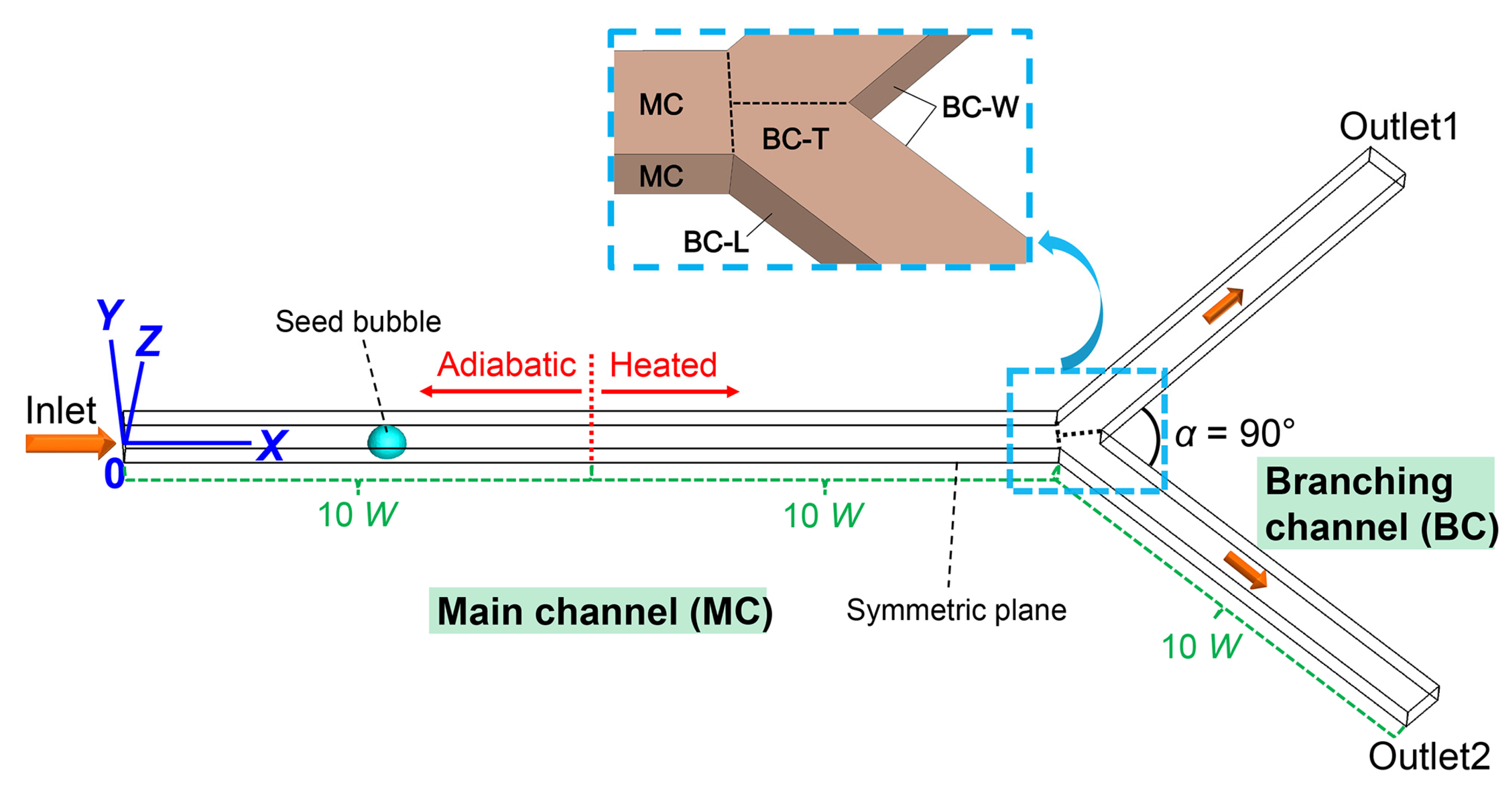
2.1. Problem Description

The illustration of the bubble motion within a heated microfluidic Y-junction is shown in Figure 1. All the channels had a width (W) of 100 μm. The microfluidic Y-junction consisted of main channel (MC, with length of 20 W) and branching channel (BC, with length of 10 W for each one), where the branching angle was 90°. We mainly concentrated on the bubble behaviors and heat transfer within the branching channel, and the different walls of BC should be distinguished. Taking the relative locations into account, the leeward (BC-L), windward (BC-W), and top (BC-T) walls were employed to represent different parts of BC.
In the present study, the boundary conditions for the inlet and outlet were, respectively, velocity inlet and pressure outlet. The boundary condition for the heated walls belonged to the constant heat flux mode, where the heat flux varied from 2000 W/m2 to 12,000 W/m2. The saturated HFE-7100 liquid entered the microfluidic Y-junction through the inlet, with the Reynolds number (Re, U·W/υ) varying from 180 to 420. The properties of HFE-7100 are gathered in Table 1 [39]. To efficiently facilitate the heat transfer performance, the seed bubble strategy was adopted [40], where the bubble diameter was fixed at 0.8 W. Before placing the seed bubble, the single-phase case was run until the velocity and temperature fields became steady. In the simulation, the contact angle for all the walls was set as 0°.

2.2. Mathematical Model

The fluid flow within microfluidic Y-junction was assumed to be incompressible and laminar. The VOF method based on the color function C was utilized to capture different phases. The vapor and liquid were set as the primary and secondary phases, respectively.
The governing equations were [6]:
Continuity Equation:
( C i ρ i ) t + ( C i ρ i U ) = S m , i
Momentum Equation:
( ρ U ) t + ( ρ U U ) = - P + ( μ ( U + U T ) ) + F s
Energy Equation:
( ρ c p T ) t + ( ρ c p T U ) = ( λ T ) + S h
The continuum surface force (CSF) model proposed by Brackbill et al. [41] was employed for the treatment of surface tension force FS:
F s = σ κ δ s n = - σ ( C | C | ) | C |
It should be mentioned that error in the CSF model may lead to obvious unphysical flow, especially for cases with small capillary number. In simulation, we used the moving reference frame technique to effectively reduce the unphysical flow [42].
Herein, the saturated-interface-volume (SIV) phase-change model was employed [43]. The model validation is showed in Section 3, and more details can be found in the literature [43,44]. By assuming that the interfacial temperature is maintained at saturated state in each iteration, the energy source added on each cell can be acquired by the following Equation (5):
S h , l a = C l ρ l c p l ( T s a t T ) + C v ρ v c p v ( T s a t T ) Δ t
The acquisition of energy source did not require nested iterations, significantly reducing the computational cost and eliminating the numerical oscillations. For the implementation of SIV model in FLUENT 17.0 [45], the UDFs were in the form of C programming language and the compiling environment was provided by Microsoft Visual Studio 2019. In the transient simulation, the Courant number was maintained at 0.1. The PISO algorithm was utilized to treat the pressure–velocity coupling, which worked well in simulation. The PRESTO and Green–Gauss node-based algorithms were responsible for the discretization of pressure and gradient, respectively. It should also be noted that a total of 2,514,708 cells were used in the simulation domain after performing the mesh independence study.

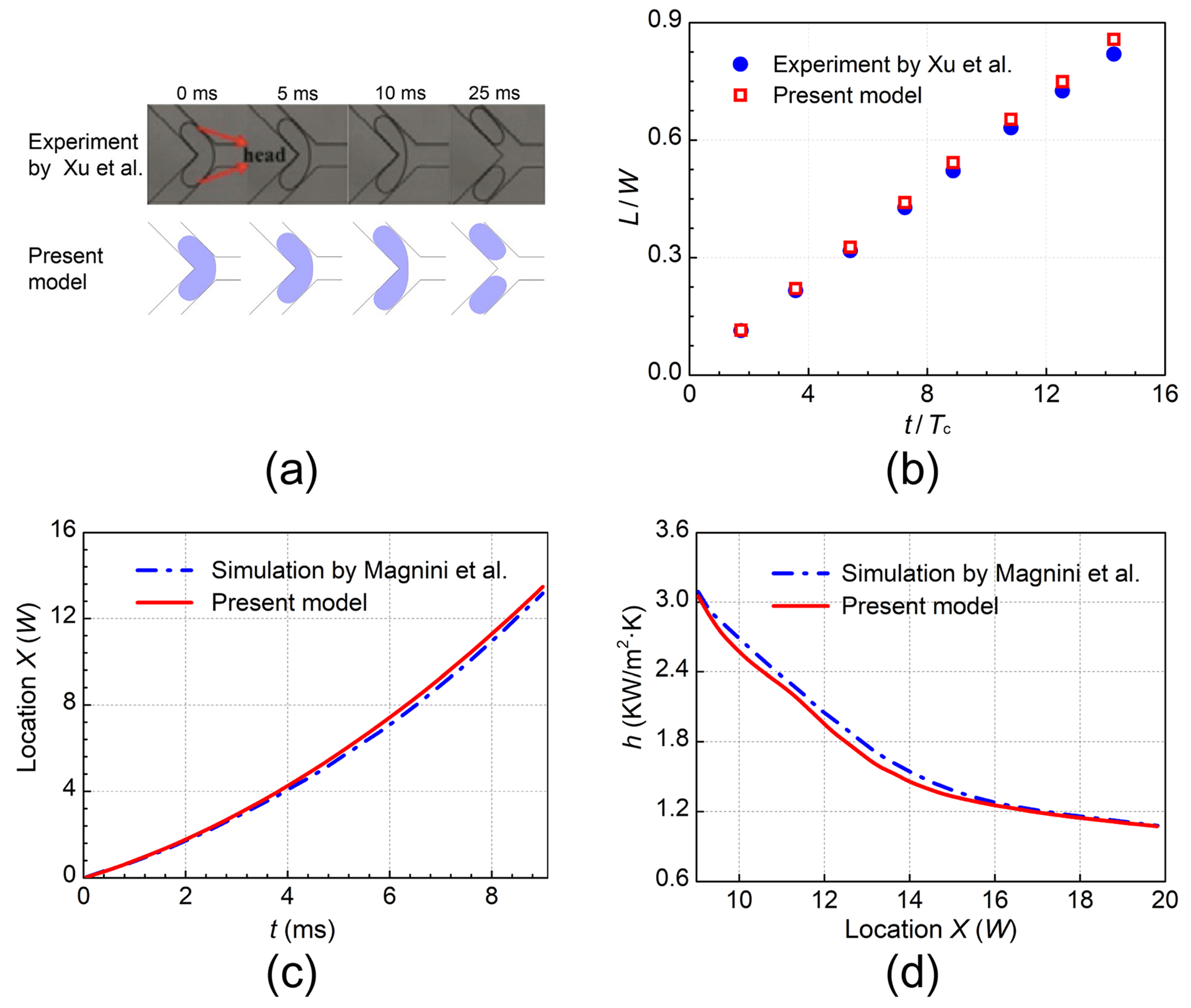
3. Verification of the Numerical Model

It was crucial to guarantee the reliability of the numerical model. Herein, two different verification cases were conducted. For the hydrodynamic model verification, the experiment performed by Xu et al. [46] was employed. In the experiment setup, the bubble passed through microfluidic Y-junction under the push of liquid. The branching angle was 90° and the channel width was 400 μm. The flow rates for gas and liquid were respectively 2.4 mL/h and 2.2 mL/h. As can be seen in Figure 2a,b, both the simulated bubble profiles and forward distance showed good agreement with experimental results by Xu et al. [46]. We also utilized the simulation from Magnini et al. [47] to verify the SIV phase change model [6]. The bubble moved and grew in a heated circular microchannel, with diameter (W) of 500 μm. The heated part of the channel had length of 12 W and heat flux of 9 KW/m2. The initial bubble length was 3 W. Figure 2c,d, respectively, show the bubble nose location and the distribution of local heat transfer, which were consistent with the simulation from Magnini et al. [47]. In brief, the established numerical model was capable of simulating the two-phase flow and phase change accurately.

4. Results and Discussion

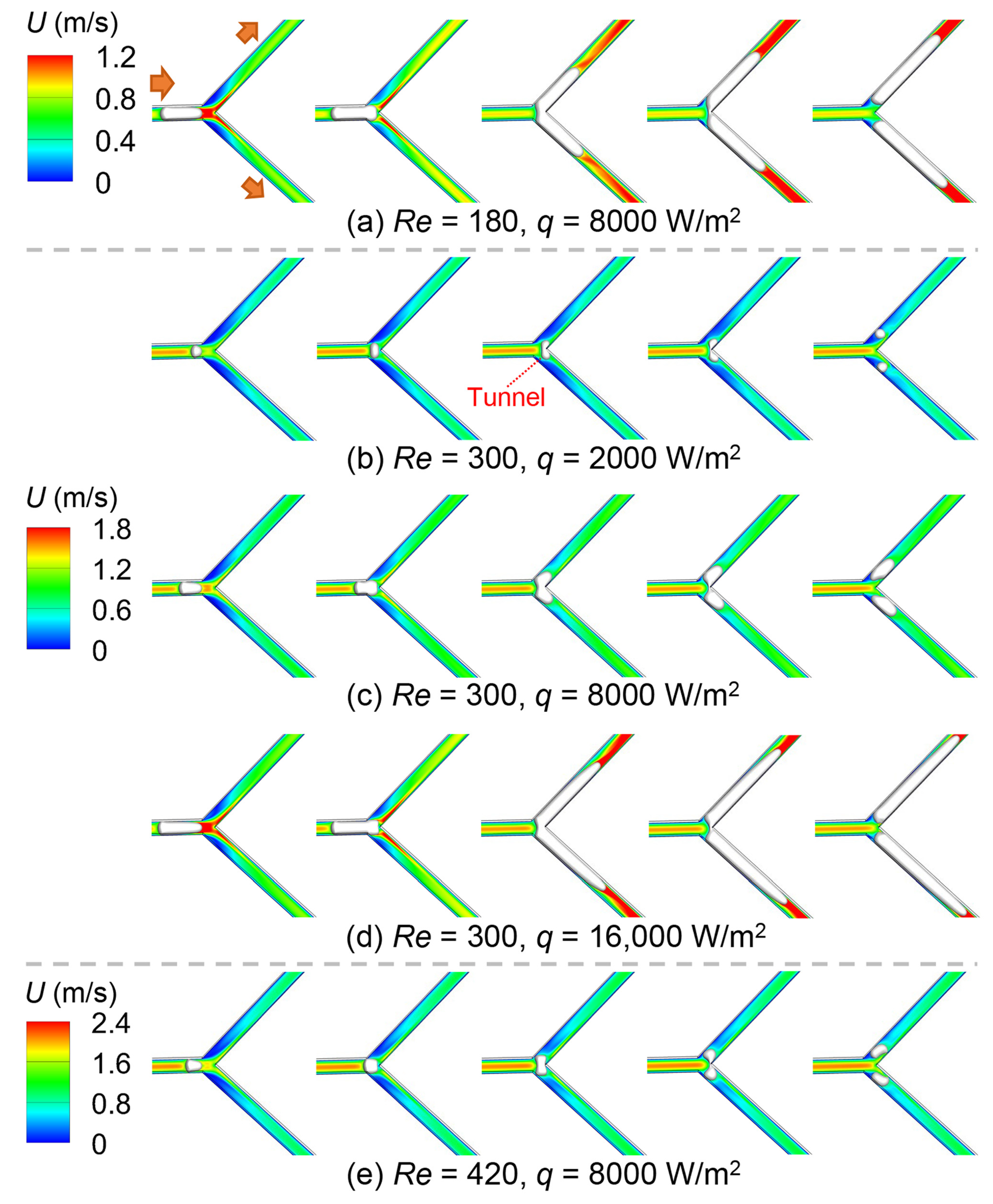
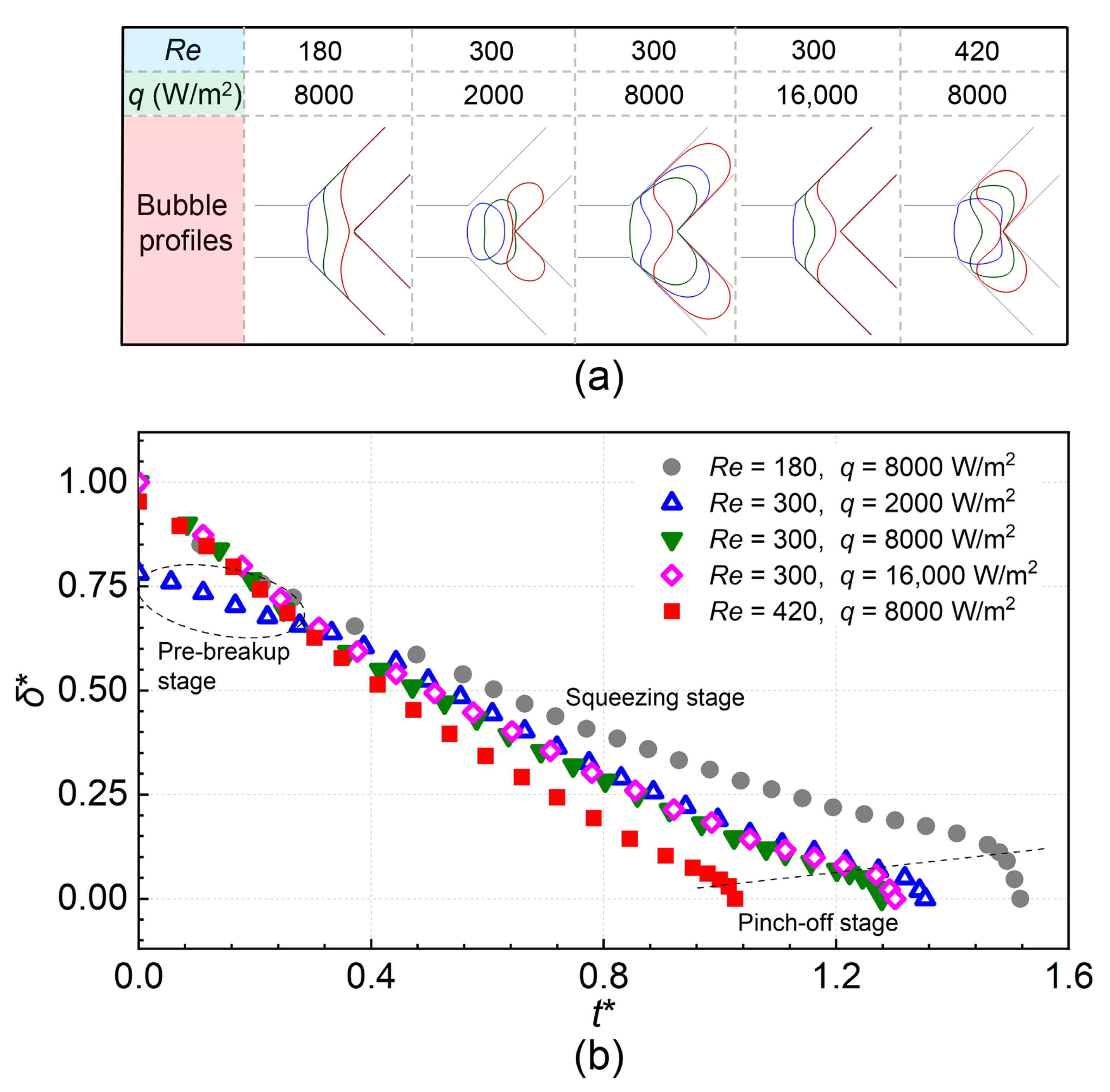
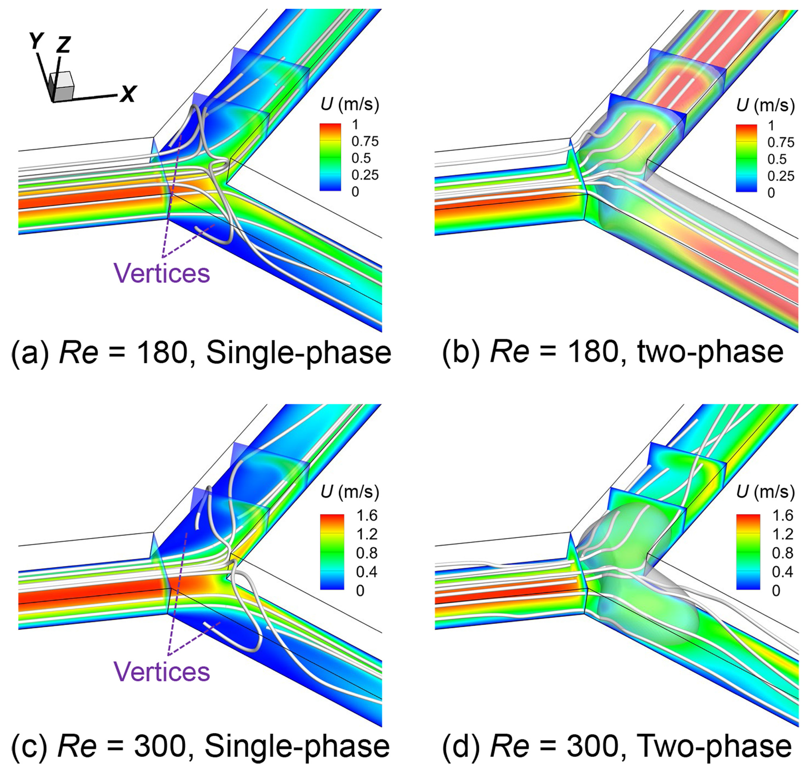
4.1. Bubble Behaviors and Flow Characteristics

Figure 3 shows the time-lapse images of the bubble profiles at different Re and q, where Re varies from 180 to 420 and q varies from 2000 W/m2 to 16,000 W/m2. The bubble was pushed forward by the fluid and symmetrically broke within divergence region, with continuous growth. By changing the heating intensity, two various breakup modes can be seen: (1) “Breakup with tunnel” emerging at low q (see Figure 3b). Under this mode, the bubble volume was still small when arriving at divergence, and thus the channel cannot be fully blocked. The liquid can easily bypass the bubble and flow to the downstream. It is worth noting that the bubble breakup was closely related to the generated shearing force [48]; (2) “Breakup with obstruction” emerging at high q. Under this mode, the significant bubble growth occurred, and the channel was fully blocked by the bubble. The liquid cannot easily bypass the bubble, and only the accumulated pressure drove the breakup process. The velocity field was significantly affected by the bubble growth characteristics, and one of the most notable features was the significant acceleration of downstream liquid at smaller Re and higher q.
The sketch of bubble profiles and the time variation of bubble neck thickness are shown in Figure 4. The dimensionless time was defined as Uin·t/W. During the breakup process, the bubble neck thickness monotonically declined, where the declining rate experienced large variations. For the earlier squeezing stage, the declining rate of neck was relatively small and uniform. It was found that this stage took up the majority of breakup process. As the time elapsed, the bubble broke more rapidly, indicating the appearance of pinch-off stage. The breakup was governed by surface tension and could not halt in this stage [10]. In other words, if the upstream liquid supply was removed, the bubble could still break into two daughter bubbles. The duration time of the pinch-off stage was much shorter than that of the squeezing stage. As a special case, in the case of q = 2000 W/m2 (with Re = 300), the bubble cannot touch the windward wall in the initial stage, which attenuates the breakup rate. This stage was named as ‘pre-breakup’ stage. Along with the increase in Re, the breakup rate increased, and the critical neck thickness for the breakup stage transition tended to decrease. Generally, the effect of q on the breakup rate was weak.
Figure 5 shows the time variation of dimensionless bubble volume (V/V0). The bubble volume increased due to evaporation, with increasing growth rate. In the later stage, the bubble evaporation area increased. The evaporation strengthened because of the low flow velocity and accumulation of sensible heat for branching channel. The fluctuations of bubble volume emerged at larger Re. The terminal bubble volume was decreased by 66.2% as Re varied from 180 to 420. The terminal bubble volume at q = 16,000 W/m2 was 7.42 times larger than that at q = 2000 W/m2.
To further reveal the mechanism of flow characteristics, the streamline profile and detailed velocity field for both single-phase and two-phase cases are shown in Figure 6. Under the single-phase case, the streamline was relatively circuitous and the symmetrical vortices occurred in proximity to leeward wall. As can be concluded from the cross-sections of the branching channel, the flow velocity in the windward wall side was much larger than that in the leeward wall side. Unlike the single-phase case, the streamline became relatively smooth, and the vortices disappeared when the bubble traveled at divergence. Moreover, the distribution of velocity for the cross-sections of branching channel tended to be more uniform.

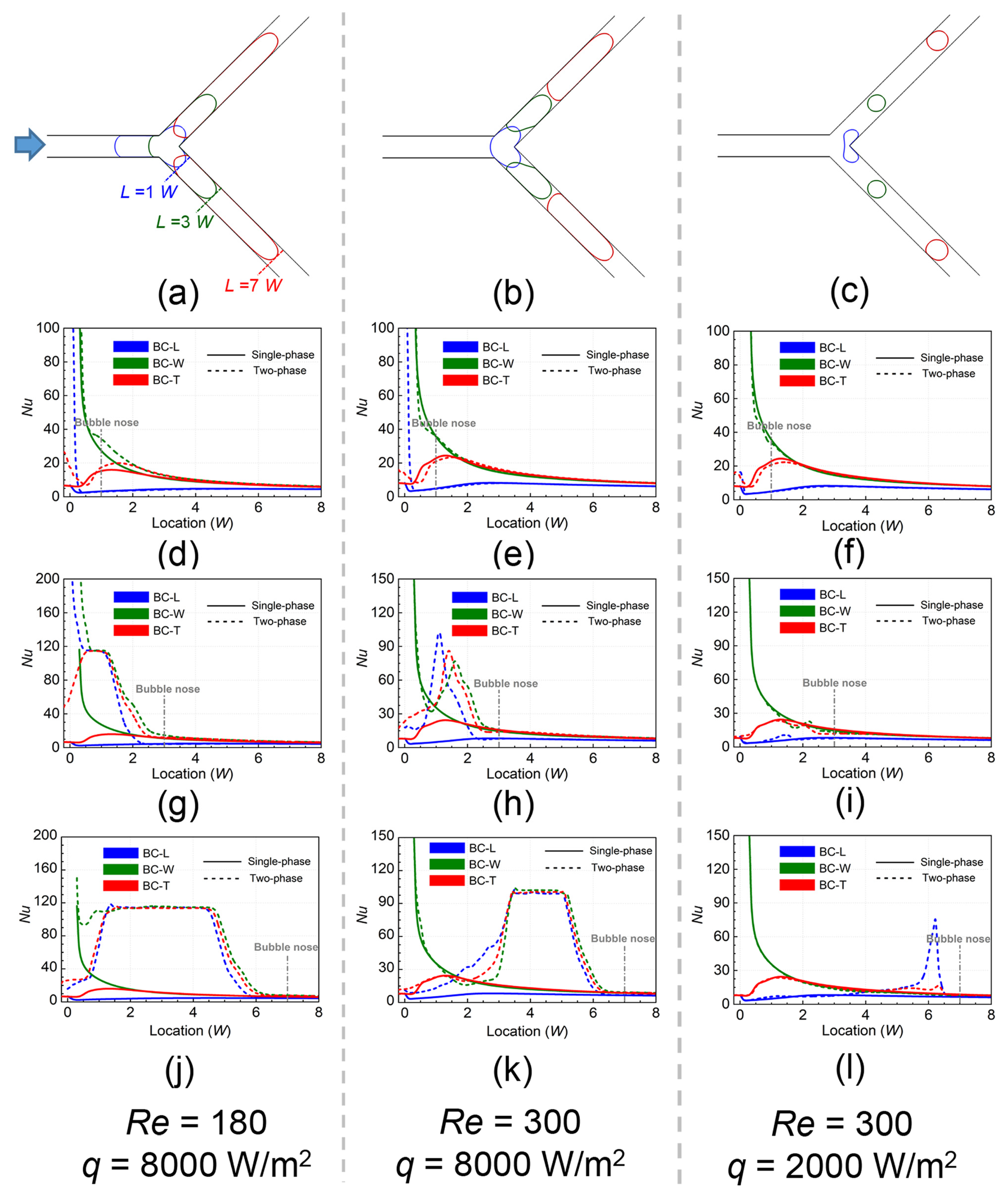
4.2. Two-Phase Heat Transfer Performance

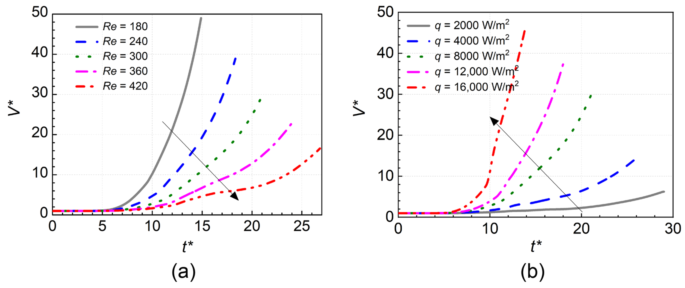
4.2.1. Transient Heat Transfer

Before moving to discussion of local distribution of heat transfer, detailed time-lapse images of the temperature field are shown in Figure 7 first. Under the single-phase case, the region near the leeward wall had higher temperature, indicating more sensible heat storage. The temperature of the heated region increased with decreasing Re and increasing q. The temperature of bubble interface was kept at saturated state. When the bubble got in contact with the superheated liquid, the phase change was activated, which absorbed the sensible heat and cooled the wall. The bigger the bubble size, the more notable a removal of sensible heat was achieved.
Figure 8 shows the time variation of the local Nusselt number (Nu). The bubble profiles are also provided (see Figure 8a–c). The heat transfer of different walls was represented by the local Nu in the center line. The definition of Nu was:
N u = q T w T s a t W λ l
where λl represented the coefficient of heat conductivity for liquid. Under the single-phase case, the Nu of BC-W wall was the largest, which was found to drastically decrease along the downstream direction. The Nu of BC-L wall was always the smallest, which was relatively smooth. Interestingly, the Nu of BC-T wall increased first and then decreased.
There were some differences between the heat transfer under single-phase case and two-phase case. For the bubble nose at 1 W (see Figure 8d–f), because the bubble did not fully touch the branching channel, the thin-film evaporation was relatively weak. Only the small part of corner produced very outstanding heat transfer performance. It should be noted that the local fluid flow was affected by the bubble, which may hinder the local heat transfer. Some local regions with negative heat transfer enhancement emerged due to the suppression effect of fluid flow. As the bubble nose located at 3 W (see Figure 8g–i), the heat transfer enhancement at q = 8000 W/m2 became notable, while it was still inconspicuous for the case of q = 2000 W/m2. The Nu at Re = 180 was larger than that at Re = 300, which was caused by the thinner liquid film thickness emerging at lower flow velocity. When the bubble nose located at downstream 7 W (see Figure 8j–l), both the affecting region and intensity of heat transfer enhancement drastically increased. At q = 2000 W/m2, the Nu in film region for BC-L wall was far larger than that for BC-W and BC-T walls. The difference in Nu in film region for different walls became tiny at q = 8000 W/m2.

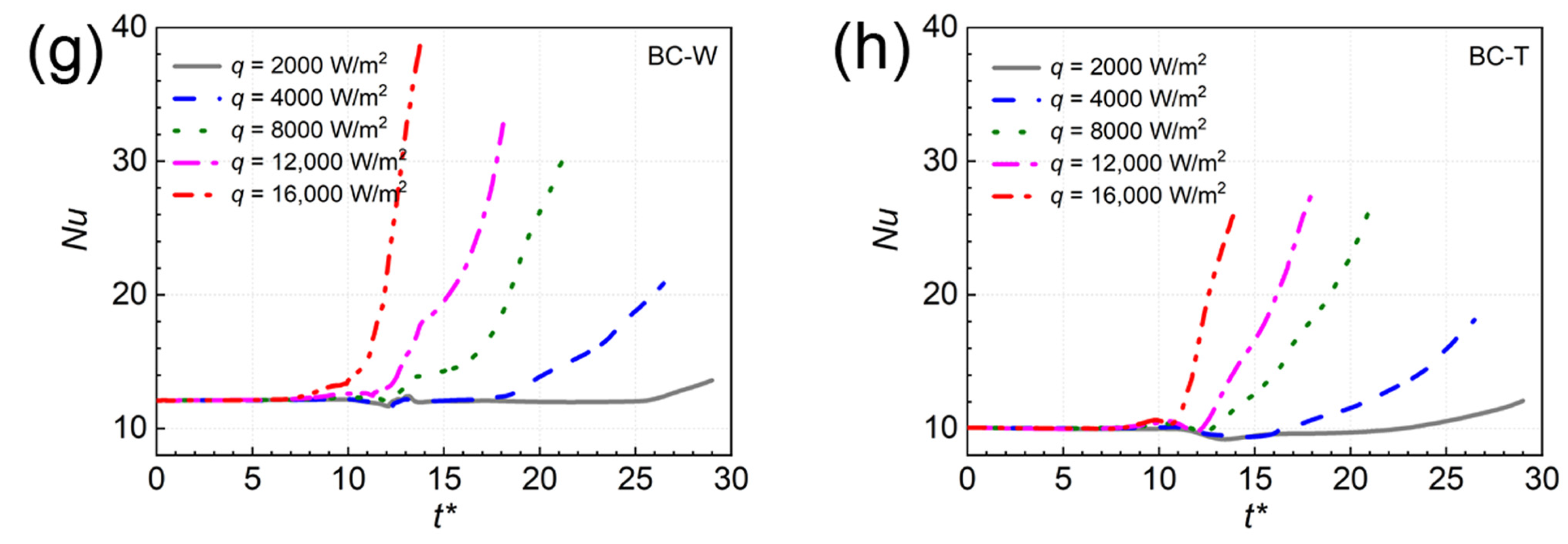
4.2.2. Time Variation of Heat Transfer

Figure 9 shows the time variation of the Nusselt number under different Re and q. Under single-phase case, the averaged heat transfer of BC-W wall was better than other walls. The Nu increased with Re owing to the improvement of convection heat transfer intensity. Under two-phase case, the Nu of MC wall rose first and then reduced. The Nu of BC walls always rose, where the small fluctuations were caused by breakup behaviors. Unlike the single-phase cases, the two-phase heat transfer at larger Re was poor. This was because that the liquid film became thicker at larger Re, which hindered the evaporating heat transfer. Overall, the Nu increased with the increase in q. One result of interest was that the maximum value of Nu for BC-L and BC-T walls did not occur at the highest q. The bubble experienced very rapid expansion at the highest q, which facilitated the velocity of the downstream part of the bubble. The local liquid film increased correspondingly, hence suppressing the heat transfer. At q = 2000 W/m2 and 4000 W/m2, it was seen that the slight negative enhancement of heat transfer existed in the BC-T wall.

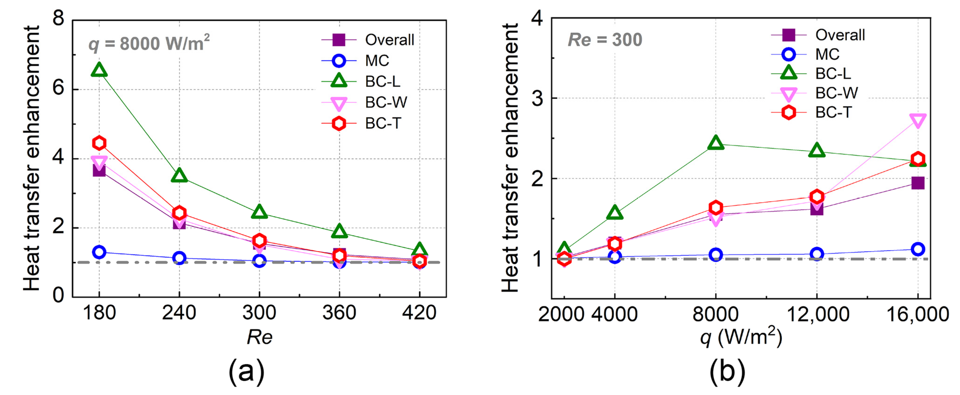
4.2.3. Heat Transfer Enhancement

The time-averaging treatment for the heat transfer enhancement (Nutp/Nusp) was conducted to directly show the evaporating heat transfer characteristics. The definition of time-averaged Nusselt number for the main channel was:
N u ¯ M C = t 1 t 2 N u M C d t t 2 t 1
where t1 and t2 respectively indicated the instants that the bubble nose just touching the heated main channel and touching the heated branching channel. The definition of the time-averaged Nusselt number for the branching channel was:
N u ¯ B C = t 2 t 3 N u B C d t t 3 t 2
where t3 indicated the instant that the bubble nose just left the heated part. The heat transfer enhancement for the overall microchannel was acquired by averaging the treatment for the heat transfer enhancement of different walls.
The time-averaged heat transfer enhancement for the microfluidic Y-junction versus Re and q is shown in Figure 10. Generally, the BC-L wall achieved the best enhancement of heat transfer, where the maximum Nu under two-phase case was 6.53 times larger than that under single-phase case. The phase change intensity for the main channel was weak, leading to poor heat transfer enhancement (less than 1.3) compared to branching channel. As Re increased from 180 to 420, the liquid film became thicker, which hindered the phase-change intensity. The falling rate of heat transfer enhancement for the overall Y-junction was 70.4%. The increase in q led to more intense evaporation, strengthening the heat transfer. The increasing rate of heat transfer enhancement for the overall Y-junction was 90.36% as q changed from 2000 W/m2 to 16,000 W/m2. Interestingly, the heat transfer of BC-L wall showed a declining trend as q exceeded 8000 W/m2. This was because the bubble breakup mode had converted to “breakup with obstruction”. The contact degree between the bubble and BC-L wall during breakup process was weakened under this mode.

5. Conclusions

In the present study, the high-fidelity simulation on the symmetric breakup of bubble within a heated microfluidic Y-junction (90°) was performed with variations of Reynolds number (Re) and heat flux (q). Two aspects were mainly studied, namely the bubble breakup behaviors and two-phase evaporating heat transfer. The main conclusions and underlying mechanisms were as follows:
  • Bubble breakup behaviors were significantly affected by evaporation. The “breakup with tunnel” and “breakup with obstruction” modes respectively occurred at low and high q. The bubble successively experienced long-period squeezing stage and short-period pinch-off stage during the breakup process, where the breakup rate under pin-off stage was much larger. Along with increase in Re, the bubble broke more rapidly, and the critical neck thickness tended to decrease. The influence of heat flux on the breakup was weak. The downstream fluid accelerated more obviously at smaller Re and higher q. The bubble annihilated the vortices existing within the divergence region and made the fluid flow more uniform.
  • The evaporating heat transfer was affected by bubble behaviors. Compared to the single-phase case, the heat transfer was drastically improved due to the evaporation under two-phase case. The most significant enhancement occurred at the leeward wall. The increase in Re promoted single-phase convective heat transfer while hindering the two-phase heat transfer. Slight negative enhancement of heat transfer existed at lower q. In addition, the phenomenon of heat transfer deterioration was observed at higher q. Generally, the heat transfer was enhanced as q was increased.
The present study not only helps understanding the physical mechanisms of bubble behaviors and heat transfer within microfluidic Y-junctions, but also informs the design of microfluidic devices.

Author Contributions

Conceptualization, J.C. (Jingbo Chen) and Z.Y.; methodology, J.C. (Jingbo Chen) and Z.Y.; software, J.C. (Jingbo Chen) and Z.Y.; formal analysis, J.C. (Jingbo Chen), W.D., B.K., Z.W., J.C. (Jun Cao), W.W. and Z.Y.; investigation, J.C. (Jingbo Chen), W.D., B.K., Z.W., J.C. (Jun Cao), W.W. and Z.Y.; writing—original draft preparation, J.C. (Jingbo Chen) and Z.Y.; writing—review and editing, Z.Y.; supervision, Z.Y.; funding acquisition, J.C. (Jingbo Chen). All authors have read and agreed to the published version of the manuscript.

Funding

This research was funded by the Major Science and Technology Project of China National Tobacco Corporation 110202001009(XX-05).

Data Availability Statement

Not applicable.

Conflicts of Interest

The authors declare no conflict of interest.

References

  1. He, Z.; Yan, Y.; Zhang, Z. Thermal management and temperature uniformity enhancement of electronic devices by micro heat sinks: A review. Energy 2021, 216, 119223. [Google Scholar] [CrossRef]
  2. Yao, C.; Zhao, Y.; Ma, H.; Liu, Y.; Zhao, Q.; Chen, G. Two-phase flow and mass transfer in microchannels: A review from local mechanism to global models. Chem. Eng. Sci. 2021, 229, 116017. [Google Scholar] [CrossRef]
  3. Seo, J.-H.; Patil, M.S.; Panchal, S.; Lee, M.-Y. Numerical Investigations on Magnetohydrodynamic Pump Based Microchannel Cooling System for Heat Dissipating Element. Symmetry 2020, 12, 1713. [Google Scholar] [CrossRef]
  4. Lu, Y.; Wang, F.; Wang, H. Boiling regimes in uncoated polydimethylsiloxane microchannels with a fine wire heater. Heat Mass Transfer. 2010, 46, 1253–1260. [Google Scholar] [CrossRef]
  5. Chen, Z.; Li, Y.; Zhou, W.; Deng, L.; Yan, Y. Design, fabrication and thermal performance of a novel ultra-thin vapour chamber for cooling electronic devices. Energy Convers. Manag. 2019, 187, 221–231. [Google Scholar] [CrossRef]
  6. Yan, Z.; Huang, H.; Li, S.; Wang, W.; Pan, Z. Three-dimensional numerical study on evaporating two-phase flow in heated micro T-junction. Chem. Eng. Sci. 2022, 250, 117375. [Google Scholar] [CrossRef]
  7. Lou, Q.; Li, T.; Yang, M. Numerical simulation of the bubble dynamics in a bifurcated micro-channel using the lattice Boltzmann method. J. Appl. Phys. 2019, 126, 034301. [Google Scholar] [CrossRef]
  8. Wang, X.; Liu, Z.; Pang, Y. Droplet breakup in an asymmetric bifurcation with two angled branches. Chem. Eng. Sci. 2018, 188, 11–17. [Google Scholar] [CrossRef]
  9. Wang, H. From contact line structures to wetting dynamics. Langmuir 2019, 35, 10233–10245. [Google Scholar] [CrossRef]
  10. Fei, Y.; Zhu, C.; Fu, T.; Gao, X.; Ma, Y. The breakup dynamics of bubbles stabilized by nanoparticles in a microfluidic Y-junction. Chem. Eng. Sci. 2021, 245, 116867. [Google Scholar] [CrossRef]
  11. Lim, A.E.; Lim, C.Y.; Lam, Y.C.; Lim, Y.H. Effect of microchannel junction angle on two-phase liquid-gas Taylor flow. Chem. Eng. Sci. 2019, 202, 417–428. [Google Scholar] [CrossRef]
  12. Liu, Z.-M.; Liu, L.-K.; Shen, F. Effects of geometric configuration on droplet generation in Y-junctions and anti-Y-junctions microchannels. Acta Mech. Sin. 2015, 31, 741–749. [Google Scholar] [CrossRef]
  13. Li, H.; Wu, Y.; Wang, X.; Zhu, C.; Fu, T.; Ma, Y. Magnetofluidic control of the breakup of ferrofluid droplets in a microfluidic Y-junction. RSC Adv. 2016, 6, 778–785. [Google Scholar] [CrossRef]
  14. Deka, D.K.; Boruah, M.P.; Pati, S.; Randive, P.R.; Mukherjee, P.P. Tuning the splitting behavior of droplet in a bifurcating channel through wettability-capillarity interaction. Langmuir 2020, 36, 10471–10489. [Google Scholar] [CrossRef] [PubMed]
  15. Ren, Y.; Koh, K.S.; Yew, M.; Chin, J.K.; Chan, Y.; Yan, Y. Droplet breakup dynamics in bi-layer bifurcating microchannel. Micromachines 2018, 9, 57. [Google Scholar] [CrossRef] [PubMed] [Green Version]
  16. Zheng, M.; Ma, Y.; Jin, T.; Wang, J. Effects of topological changes in microchannel geometries on the asymmetric breakup of a droplet. Microfluid. Nanofluid. 2016, 20, 107. [Google Scholar] [CrossRef]
  17. Wang, X.; Hirano, H.; Xie, G.; Xu, D. VOF modeling and analysis of the segmented flow in Y-shaped microchannels for microreactor systems. Adv. High Energy Phys. 2013, 2013, 732682. [Google Scholar] [CrossRef]
  18. Yan, Z.; Pan, Z. Dynamics and phase change heat transfer of an isolated vapor bubble traveling through a heated T-shaped branching microchannel. Int. J. Heat Mass Transf. 2020, 160, 120186. [Google Scholar] [CrossRef]
  19. Yan, Z.; Li, L.; Pan, Z. Breakup regime and heat transfer of a vapor bubble within T-shaped branching microchannel. Int. J. Heat Mass Transf. 2021, 175, 121344. [Google Scholar] [CrossRef]
  20. Tiwari, N.; Moharana, M.K. Conjugate heat transfer analysis of liquid-vapor two phase flow in a microtube: A numerical investigation. Int. J. Heat Mass Transf. 2019, 142, 118427. [Google Scholar] [CrossRef]
  21. Zhang, C.; Chen, L.; Ji, W.; Liu, Y.; Liu, L.; Tao, W.-Q. Lattice Boltzmann mesoscopic modeling of flow boiling heat transfer processes in a microchannel. Appl. Therm. Eng. 2021, 197, 117369. [Google Scholar] [CrossRef]
  22. Chen, J.; Ahmad, S.; Deng, W.; Cai, J.; Zhao, J. Micro/nanoscale surface on enhancing the microchannel flow boiling performance: A Lattice Boltzmann simulation. Appl. Therm. Eng. 2022, 205, 118036. [Google Scholar] [CrossRef]
  23. Qiu, J.; Zhou, J.; Zhao, Q.; Qin, H.; Chen, X. Numerical investigation of flow boiling characteristics in cobweb-shaped microchannel heat sink. Case Stud. Therm. Eng. 2021, 28, 101677. [Google Scholar] [CrossRef]
  24. Li, W.; Luo, K.; Li, C.; Joshi, Y. A remarkable CHF of 345 W/cm2 is achieved in a wicked-microchannel using HFE-7100. Int. J. Heat Mass Transf. 2022, 187, 122527. [Google Scholar] [CrossRef]
  25. Qiu, J.; Zhao, Q.; Lu, M.; Zhou, J.; Hu, D.; Qin, H.; Chen, X. Experimental study of flow boiling heat transfer and pressure drop in stepped oblique-finned microchannel heat sink. Case Stud. Therm. Eng. 2022, 30, 101745. [Google Scholar] [CrossRef]
  26. Yuan, B.; Liu, L.; Cui, C.; Fang, J.; Zhang, Y.; Wei, J. Micro-pin-finned surfaces with fractal treelike hydrophilic networks for flow boiling enhancement. ACS Appl. Mater. Interfaces 2021, 13, 48189–48195. [Google Scholar] [CrossRef]
  27. Yin, L.; Jiang, P.; Xu, R.; Hu, H. Water flow boiling in a partially modified microgap with shortened micro pin fins. Int. J. Heat Mass Transf. 2020, 155, 119819. [Google Scholar] [CrossRef]
  28. Deng, D.; Zeng, L.; Sun, W.; Pi, G.; Yang, Y. Experimental study of flow boiling performance of open-ring pin fin microchannels. Int. J. Heat Mass Transf. 2021, 167, 120829. [Google Scholar] [CrossRef]
  29. Xia, G.; Cheng, Y.; Cheng, L.; Li, Y. Heat transfer characteristics and flow visualization during flow boiling of acetone in semi-open multi-microchannels. Heat Transf. Eng. 2018, 40, 1349–1362. [Google Scholar] [CrossRef] [Green Version]
  30. Vontas, K.; Andredaki, M.; Georgoulas, A.; Miché, N.; Marengo, M. The effect of surface wettability on flow boiling characteristics within microchannels. Int. J. Heat Mass Transf. 2021, 172, 121133. [Google Scholar] [CrossRef]
  31. Zhao, Q.; Qiu, J.; Zhou, J.; Lu, M.; Li, Q.; Chen, X. Visualization study of flow boiling characteristics in open microchannels with different wettability. Int. J. Heat Mass Transf. 2021, 180, 121808. [Google Scholar] [CrossRef]
  32. Hsu, W.-T.; Lee, D.; Lee, N.; Yun, M.; Cho, H.H. Enhancement of flow boiling heat transfer using heterogeneous wettability patterned surfaces with varying inter-spacing. Int. J. Heat Mass Transf. 2021, 164, 120596. [Google Scholar] [CrossRef]
  33. Lin, Y.; Luo, Y.; Li, J.; Li, W. Heat transfer, pressure drop and flow patterns of flow boiling on heterogeneous wetting surface in a vertical narrow microchannel. Int. J. Heat Mass Transf. 2021, 172, 121158. [Google Scholar] [CrossRef]
  34. Criscuolo, G.; Markussen, W.B.; Meyer, K.E.; Kærn, M.R. High heat flux flow boiling of R1234yf, R1234ze(E) and R134a in high aspect ratio microchannels. Int. J. Heat Mass Transf. 2022, 186, 122215. [Google Scholar] [CrossRef]
  35. Qi, Z.; Jia, L.; Dang, C.; Zhang, Y. Liquid mass transfer characteristics of zeotropic mixtures of R134a/R245fa during flow boiling in a rectangular channel. Int. J. Heat Mass Transf. 2022, 187, 122551. [Google Scholar] [CrossRef]
  36. Kingston, T.A.; Olson, B.D.; Weibel, J.A.; Garimella, S.V. Transient flow boiling and maldistribution characteristics in heated parallel channels induced by flow regime oscillations. IEEE Trans. Compon. Packag. Manuf. Technol. 2021, 11, 10. [Google Scholar] [CrossRef]
  37. Lu, Q.; Zhang, Y.; Liu, Y.; Zhou, L.; Shen, C.; Chen, D. An experimental investigation on the characteristics of flow instability with the evolution of two-phase interface morphology. Int. J. Heat Mass Transf. 2019, 138, 468–482. [Google Scholar] [CrossRef]
  38. Alugoju, U.K.; Dubey, S.K.; Javed, A. 3D Transient heat transfer analysis and flow visualization study in diverging microchannel for instability mitigated two-phase flow: A numerical study. Int. J. Heat Mass Transf. 2020, 160, 120212. [Google Scholar] [CrossRef]
  39. NIST. NIST Chemistry Web Book; NIST: Gaithersburg, MD, USA, 2018. [Google Scholar] [CrossRef]
  40. Xu, J.; Zhang, W.; Liu, G. Seed bubble guided heat transfer in a single microchannel. Heat Transf. Eng. 2011, 32, 1031–1036. [Google Scholar] [CrossRef]
  41. Brackbill, J.U.; Kothe, D.B.; Zemach, C. A continuum method for modeling surface tension. J. Comput. Phys. 1992, 100, 335–354. [Google Scholar] [CrossRef]
  42. Pan, Z.; Weibel, J.A.; Garimella, S.V. Spurious current suppression in VOF-CSF simulation of slug flow through small channels. Numer. Heat Transf. A Appl. 2014, 67, 1–12. [Google Scholar] [CrossRef]
  43. Pan, Z.; Weibel, J.A.; Garimella, S.V. A saturated-interface-volume phase change model for simulating flow boiling. Int. J. Heat Mass Transf. 2016, 93, 945–956. [Google Scholar] [CrossRef] [Green Version]
  44. Yan, Z.; Huang, H.; Pan, W.; Deng, B.; Pan, Z. Influences of wall superheat and channel width ratio on bubble behaviors and heat transfer within a heated microchannel T-junction. Int. Commun. Heat Mass Transf. 2021, 126, 105481. [Google Scholar] [CrossRef]
  45. Fluent. ANSYS FLUENT 17.0: User’s Guide; ANSYS-Fluent Inc.: Canonsburg, PA, USA, 2016. [Google Scholar]
  46. Ziyi, X.; Taotao, F.; Chunying, Z.; Shaokun, J.; Youguang, M.; Kai, W.; Guangsheng, L. Dynamics of partially obstructed breakup of bubbles in microfluidic Y-junctions. Electrophoresis 2019, 40, 376–387. [Google Scholar] [CrossRef]
  47. Magnini, M.; Pulvirenti, B.; Thome, J.R. Numerical investigation of hydrodynamics and heat transfer of elongated bubbles during flow boiling in a microchannel. Int. J. Heat Mass Transf. 2013, 59, 451–471. [Google Scholar] [CrossRef]
  48. Fu, T.; Ma, Y.; Funfschilling, D.; Li, H.Z. Dynamics of bubble breakup in a microfluidic T-junction divergence. Chem. Eng. Sci. 2011, 66, 4184–4195. [Google Scholar] [CrossRef]
Figure 1. Illustration of the bubble motion within a heated microfluidic Y-junction.
Symmetry 14 01661 g001
Figure 2. Verifications of hydrodynamic model (a,b) and phase change model (c,d). Xu et al. [46]; Magnini et al. [47].
Symmetry 14 01661 g002
Figure 3. Time-lapse images of the bubble profiles at different Re and q.
Symmetry 14 01661 g003
Figure 4. Sketch of bubble profiles (a) and the time variation of bubble neck thickness (b).
Symmetry 14 01661 g004
Figure 5. Time variation of dimensionless bubble volume at different Re (a) and q (b).
Symmetry 14 01661 g005
Figure 6. Streamline profile and detailed velocity field for both single-phase and two-phase cases.
Symmetry 14 01661 g006
Figure 7. Time-lapse images of the temperature field at different Re and q.
Symmetry 14 01661 g007
Figure 8. Time variation of the local Nusselt number. (ac) show the bubble profiles. (df), (gi), and (jl) respectively correspond to the instants of bubble nose locating at 1 W, 3 W, and 7 W.
Symmetry 14 01661 g008
Figure 9. Time variation of the averaged Nusselt number for different walls. (ad), (eh) respectively show the effects of Re and q on the averaged Nusselt number.
Symmetry 14 01661 g009aSymmetry 14 01661 g009b
Figure 10. Time-averaged heat transfer enhancement for the microfluidic Y-junction versus Re (a) and q (b).
Symmetry 14 01661 g010
Table 1. Physical properties of HFE-7100 medium [39].
PropertiesLiquidVapor
ρ (kg/m3)14255.15
μ (Pa·s)3.56 × 10−41.11 × 10−5
σ (N/m)0.01360.0136
cp (kJ/(kg·K))1.4300.900
λ (W/(m·K))0.06180.0103
hfg (kJ/kg)117.8117.8
Publisher’s Note: MDPI stays neutral with regard to jurisdictional claims in published maps and institutional affiliations.

