Article

Performance-Based Seismic Design of Hybrid Isolation Systems with Gap-Tunable BRBs for Bearing-Supported Bridges

1
School of Architecture and Civil Engineering, Xi’an University of Science and Technology, Xi’an 710054, China
2
State Key Laboratory for Strength and Vibration of Mechanical Structures, School of Aerospace Engineering, Xi’an Jiaotong University, Xi’an 710049, China
3
CCCC First Highway Consultants Co., Ltd., Xi’an 710068, China
*
Author to whom correspondence should be addressed.
Symmetry 2022, 14(7), 1373; https://doi.org/10.3390/sym14071373
Submission received: 6 June 2022 / Revised: 28 June 2022 / Accepted: 29 June 2022 / Published: 3 July 2022
(This article belongs to the Special Issue Symmetry in Safety and Disaster Prevention Engineering)

Abstract

:
This study proposes a class of hybrid isolation systems constructed by combining Buckling Restrained Braces (BRBs) with Rubber Bearings (RBs) or Lead Rubber Bearings (LRBs) for mitigating the seismic responses in bearing-supported bridges under strong earthquakes. Firstly, two different hybrid isolation systems (RB–BRB and LRB–BRB) were preliminarily designed based on the energy-conservation concept in the case of a bridge with Y-shaped piers, which can meet all the energy demands at different seismic hazard levels. Further, seismic evaluations were conducted on the bridges with the LRB, RB–BRB, and LRB–BRB isolation systems based on the nonlinear time history analyses. The proposed hybrid isolation systems show a two-phase energy dissipation behavior, which facilitates the systems to reduce the seismic responses remarkably under different earthquake scenarios and achieve most of the performance objectives corresponding to the code-specified hazard levels. Finally, based on fragility analyses, the effects of the gap spacing and the stiffness ratio of the BRB to the pier were investigated with respect to the failure probability in the case of a bridge with LRB–BRB. It has been validated that the seismic performances of this study’s bridge can be improved considerably with the optimized gap spacing and BRB stiffness.

1. Introduction

Earthquake-induced downtime and the permanent damage to some important bridges have large consequences in terms of economics and safety [1,2,3]. There is a need for designers to simultaneously achieve strength and seismic performance requirements. Generally, the strength of continuous bridges can be enhanced by the rational design of the structural components, such as girders, piers, and abutments. This increases the structural stiffness and thereby affects the seismic performance of the bridge under different seismic intensities. For the seismic design of bridges under strong earthquakes, isolation devices are usually installed between the deck and the piers to mitigate dynamic responses [4,5], since bearings or isolations are more readily replaced or repaired than structural components.
The isolation devices can be categorized by function into either seismic isolation devices (bearings) or energy dissipation devices (dampers). In practice, the mass production of the Rubber Bearing (RB), the Lead Rubber Bearing (LRB) [6], and the Buckling Restrained Brace (BRB) [7] with specified standards has led to these products being available in markets due to their advantages in cost, efficiency, and reliability in service environments. Among these, conventional RBs and LRBs have been widely applied in bearing-supported bridges for economic benefits in mild seismic zones; however, they are criticized for their excessive shear deformation under strong earthquake shakings. On the other hand, BRBs have a large energy dissipation capacity for resisting unexpected deformation during strong earthquakes but may transfer increased seismic loads to substructures during moderate earthquakes.
Compared with individual isolators, the hybrid isolation system has many advantages because it exploits the merits of its isolators and has been investigated extensively. Kim et al. [8] combined BRBs with a viscoelastic damper to improve the tested structure’s structural lateral stiffness and wind-induced vibration performance at the same time. Li et al. [9] proposed a hybrid isolation system consisting of a BRB and a viscous damper to protect a high-rise building from the multi-hazards of earthquakes and wind, which effectively dissipated energy under multiple hazard scenarios. Marshall et al. [10] combined BRB with a high damping rubber damper to construct a multiphase energy dissipation device that can be adjusted artificially to reduce the dynamic responses at different seismic intensities. Moreover, BRBs were combined with self-centering bracing to simultaneously mitigate the seismic responses and the residual displacement of structures [11,12]. These studies demonstrated BRB as an effective energy dissipation damper that could be combined with other isolators for the innovative seismic protection of structures under different earthquake intensities.
The seismic design of bridges advances with the development of isolation systems. In the performance-based seismic design, the performance criteria are usually defined by the structural responses at a specified seismic hazard level [13]. Based on the identical displacement-based design criteria, Xiang et al. [14] evaluated the seismic performances of bridges retrofitted with different energy dissipation braces under design earthquakes. Calvi et al. [15] simplified the isolated bridge as an Equivalent Single-Degree-of-Freedom (ESDF) system and validated the ESDF model in a preliminary seismic design for both regular and irregular bridges based on deck displacement.
For a practical seismic design, Yang et al. [16] proposed an Equivalent Energy Design Procedure (EEDP) in the seismic design of a fused truss moment frame, allowing designers to achieve the target performance at a certain earthquake intensity without complicated iterations. By using the EEDP, Sadeghi et al. [17] conducted seismic analyses on bridges retrofitted with a rocking dual-fused system. This innovative isolation system helps the bridge achieve the targeted performance at different seismic intensities. Guo et al. [18] improved the EEDP for the seismic design of a multi-degree-of-freedom system, such as a high-speed railway bridge, supported by friction pendulum bearings where the pier mass should be considered. The EEDP is based on the concept of energy conservation by equating the strain energy and hysteresis energy of a realistic nonlinear system to the strain energy of its assumed elastic system. Considering the nonlinear characteristic of the hysteresis energy, this energy equivalence cannot be obtained unless the energy of the realistic system is modified by a factor larger than unity. However, the determination of the modification factor needs a lot of nonlinear dynamic analyses and iterations. Particularly for complicated structures, such as the bridges with hybrid isolations, the accurate estimation of the modification factor becomes impractical.
In preliminary seismic design, an empirical modification factor can be utilized to simplify the EEDP. With the empirical modification factor, the rational energy dissipation can be estimated, and thus the placement, size, and capacity of the intended isolation systems can be determined. Furthermore, an optimal design of the isolation system could be obtained based on the nonlinear dynamic analyses of the whole bridge system. Many optimum approaches, such as the steepest descent search algorithm [19], the genetic algorithm [20], the resilience-based method [21], and the fragility-based method [22], were reported to be capable of simultaneously improving both the seismic and structural performances. For example, Montazeri et al. [23] utilized a fragility analysis to evaluate the impact of the individual BRB and LRB on the damage probability of bridges. The structural fragility is an overall indicator related to bridges’ corresponding damage states that can be rationally correlated with the performance-based design criteria. Thus, the fragility-based method is utilized herein to obtain the optimal seismic design of the hybrid isolation systems by evaluating the structural fragilities in bridges under different seismic hazard levels.
The objective of this work is to develop a class of novel hybrid isolation systems that are composed of conventional LRBs and gap-tunable BRBs for the seismic design of bridges. The novelty of the current study is that based on the simplified EEDP and fragility analyses, a performance-based optimal design is proposed for bearing-supported bridges by tuning the gap spacing and stiffness of BRBs. The present work is organized as follows. First, we performed a preliminary seismic design for a case bearing-supported bridge with gap-tunable BRBs based on a simplified EEDP. Then, seismic analyses of bridges with different isolation systems were performed to evaluate the seismic performances of bridges at different seismic intensities. Based on the seismic responses, fragility analyses were performed to discuss the effects of the tunable gap spacing and stiffness of BRBs on the vulnerability of both bearings and piers at different damage states. Finally, a practical optimum design of the LRB–BRB isolation system was suggested to achieve better seismic performances for similar bridges.

2. Models and Methods

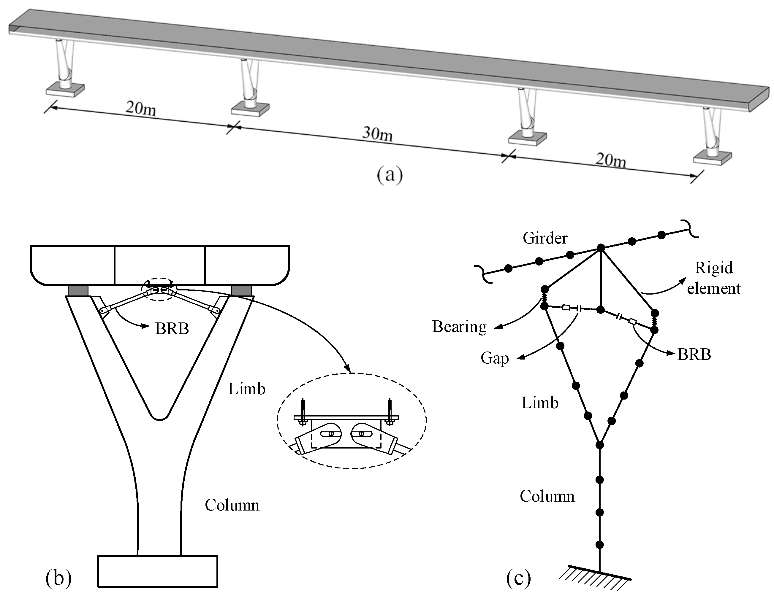
2.1. Prototype Bridge Modeling

A three-span symmetrical pedestrian bridge with Y-shaped piers located in Xi’an, China, was considered as the prototype model, as shown in Figure 1a. The superstructure is a continuous steel-concrete composite girder with a deck section width of 7.0 m and height of 1.0 m. The substructure is made of four Y-shaped piers of similar height. Each pier is assembled by one vertical column with a height of 2.0 m and two inclined limbs with a height of 3.0 m. The center-to-center spacing of limb tops is 4.6 m. In the prototype bridge, the deck is supported by eight Rubber Bearings (RBs) seated on the limb tops of the four Y-shaped piers. Both limbs and columns are made of Concrete Filled Steel Tubes (CFSTs) with circular section diameters of 0.6 m and 0.8 m, respectively. The deck section and the typical CFST Y-shaped pier are shown in Figure 1b.
The finite element model of the prototype bridge was built by using the nonlinear dynamic analysis program OpenSees [24]. In the bridge model, the girder and piers were modeled by the elasticBeamColumn and dispBeamColumn, respectively. For modeling the CFST piers, steel tubes with a thickness of 16 mm were modeled by the Steel02 element with mechanical properties derived from the Giuffre–Menegotto–Pinto model [25]. The infilled concrete was modeled with confined concrete by using the Concrete02 element with mechanical parameters described by the Kent–Park model [26,27]. A standard type of RB [28] with a height of 0.069 m was modeled by the zero-length element (Steel01). The RBs, designed according to their vertical loading requirements, would yield at the shear strain of 100% with the initial shear stiffness kb of 2180 kN/m and post-yielding stiffness of 21.8 kN/m.
In the case of this bridge, dynamic response along the transverse direction is crucial since excessive shear displacement in the bearings will result in the unseating failure of the bridge deck [29]. To mitigate the seismic responses, a pair of BRBs combined with a gap in the symmetrical ‘Chevron’ configuration can be installed between the inner sides of limbs and the deck bottom. The pair of BRBs can be modeled for placement at the same level of the limb tops by an inclined angle of 5°. The finite element model of the typical pier installed with the BRBs and bearings is illustrated in Figure 1c. Usually, the soil-structure interaction (SSI) is beneficial to structural performance since it may introduce additional flexibility and damping to structures [30]. Thus, the SSI can be ignored, when pursuing a conservative design, except for important bridges where economic impact matters, in long-span bridges where multiple support excitation should be considered, or in asymmetrical rigid structures founded on soft soils where the detrimental effect of SSI may arise [31,32]. In this work, the case bridge was a symmetrical short-span flexible bridge. For the computational efficiency of the dynamic analyses, the soil–structure interaction between piers and the earth was neglected by rigidly fixing the column ends with the ground.

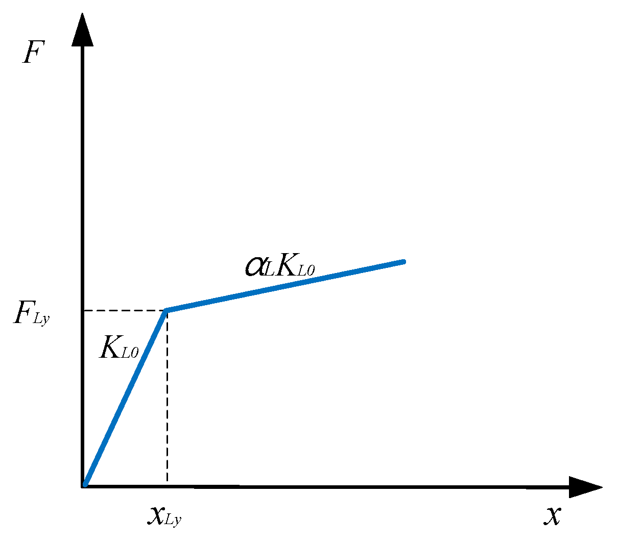
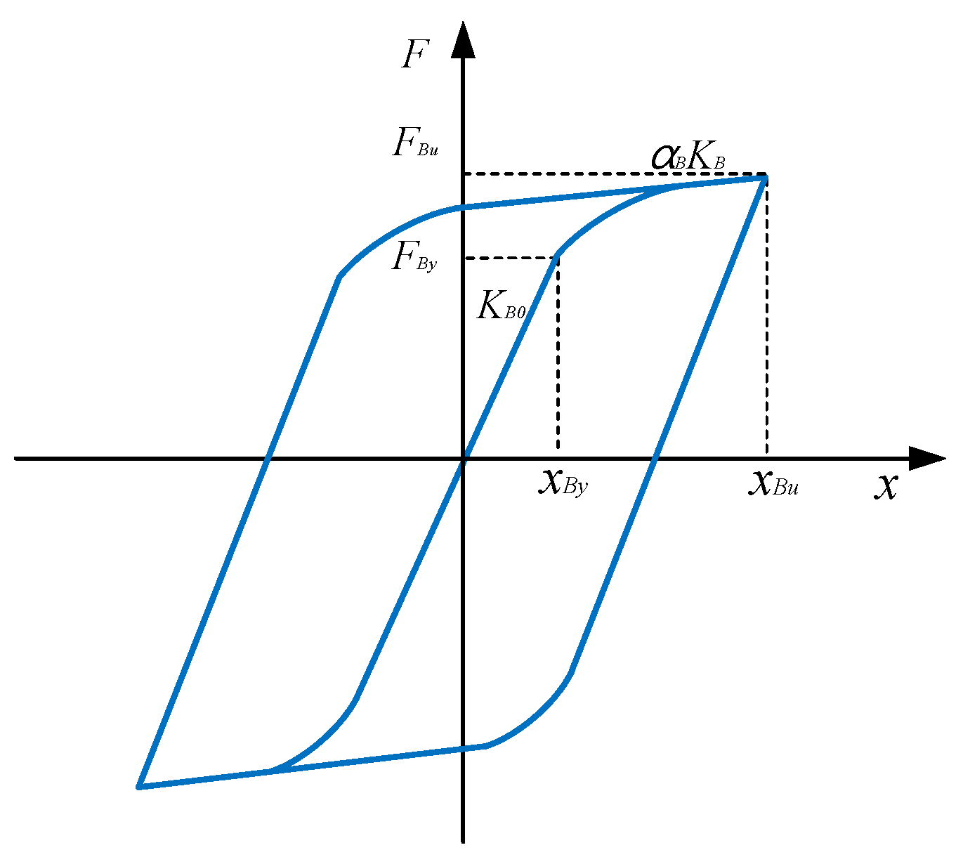
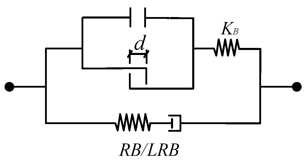
2.2. Modelling of Isolation Systems

Three types of isolation schemes are considered in this study: replacing RBs in prototype bridge with LRBs, adding BRBs to assist RBs to construct a hybrid RB–BRB isolation system, and combining BRBs with LRBs to construct a hybrid LRB–BRB isolation system. In the RB and LRB individual isolators, both act as bearings to isolate shear or dissipate energy, while in the RB–BRB and LRB–BRB hybrid isolation schemes, BRBs activate after the first deformation stage of bearings. For preliminary design, the initial mechanical parameters of the typical isolation devices are listed in Table 1.
In the bridge supported by individual LRBs, a standard type of LRB [28] with a deformable height of 0.169 m is modeled by the elastomeric bearing elements. For each LRB, the idealistic force–displacement curve is shown in Figure 2, and its post-yielding stiffness KLy can be expressed as:
KLy = αLKL0
FLy = KL0xLy
where KL0 is the initial stiffness, αL is the ratio of the post-yielding stiffness to the initial stiffness, FLy is the yield force, and xLy is the yield displacement. For the LRB selected according to the vertical load-carrying requirement, the initial stiffness KL0 is 6.2 × 10⁶ N/m, the post-yielding stiffness is 1.0 × 10⁶ N/m, the yield force FLy of its lead core is 6.2 × 10⁴ N, the yield displacement xLy is 0.01 m, the elastic modulus EL is 2.0 GPa, and the vertical stiffness is 1.64 × 10⁹ N/m.
In the bridge with RB–BRB, BRBs are modelled by truss elements made of symmetrical isotropic hardened steel (Steel02) with yield strength of 185.0 MPa and elastic modulus of 2.06 × 10³ GPa. The post-yielding stiffness (KBy) can be expressed as:
KBy = αBKB0
FBy = xByKB0
The typical hysteretic curve of a BRB under cyclic loading is shown in Figure 3. In the preliminary design, the steel core area of the initially selected BRB is 500 mm2, the initial axial stiffness KB0 is calculated as 49,047 kN/m, αB is the ratio of the initial stiffness to the post-yielding stiffness with a constant value at 0.01, and the yield displacement xBy is 2.0 mm.
To adjust the yielding of BRBs, two combined gaps are set between the top ends of a pair of BRBs and the bottom of the deck in series. The schematic detailing of the combined gaps in the gusset plate is shown in Figure 1. The combined gap model is constructed by assembling a tension gap unit with a compression gap unit in parallel. Then, the combined gap connects with a BRB in series forming a gap-tunable BRB. Here, the BRB serves as an additional energy dissipation component in parallel with RB, forming an RB–BRB isolation system, as depicted in Figure 4. In this hybrid system, the combined gaps can provide the pair of BRBs with an artificial spacing of d to delay their activation.
The force (F) in RB–BRB can thus be calculated by Equation (1). If the relative shear displacement (Δx) between the deck and the pier tops is greater than d, one of the gap units will be closed, and the BRB will be tensioned or compressed. If Δx is smaller than d, both gap units remain open, and the BRB will not be activated. Usually, the gap spacing d in the RB–BRB model is less than xRy. The idealized force–displacement curve of the RB-RBB is shown in Figure 5a, where BRB begins to take loads at a shear displacement of initial d and yields before the yielding of RB. In this model, four stiffnesses along the curve are sequentially K1 = KR0, K2 = KR0 + KB0, K3 = KR0 + αRKB0, and K4 = αRKR0 + αBKB0, with three transition points corresponding to shear forces at Fy1 = dK1, Fy2 = Fy1 + K2(xByd), and Fy3 = Fy2 + K3(xRyxBy), respectively.
F = { K B ( Δ x d )             ( Δ x d ) 0                                           ( d < Δ x < d ) K B ( Δ x + d )             ( Δ x d )
Due to the early yielding of the lead core, LRBs can dissipate more energy than RBs under the same earthquake shaking. By replacing RBs of the RB–BRB with LRBs, the LRB–BRB isolation system can be constructed with improved energy dissipation capacity. The force–displacement relationship of the LRB–BRB with the initial gap spacing (d = 35 mm) is shown in Figure 5b. Usually, the gap spacing in the LRB–BRB is larger than xLy, thus BRBs will activate in the post-yielding stage of LRBs, rendering a stair-like quadrilinear curve. In this model, four stiffnesses along the curve are sequentially K1 = KL0, K2 = αLKL0, K3 = αLKL0 + KB0, and K4 = αLKL0 + αBKB0 with three transitions corresponding to shear forces at Fy1 = FLy, Fy2 = Fy1 + K2(dxLy), and Fy3 = Fy2 + K3xBy.

2.3. Multi-Level Earthquakes and Performance Objectives

In this work, typical ground motion records [33], including 7 far-fault (FF), 7 near-fault (NF), and 7 pulse-like near-fault (PNF) earthquakes, were selected from Pacific Earthquake Engineering Research (PEER) strong motion database [34]. The magnitude, Peak Ground Acceleration (PGA), the Peak Ground Velocity (PGV), and the average shear wave velocity (Vs_30) for soil layers within 30 m below the ground surface of the selected FF, NF, and PNF earthquakes are listed in Table 2, Table 3 and Table 4, respectively. The frequency contents of the selected time histories were modified using the time domain spectral matching method proposed by Al Atik and Abrahamson [35] to match their response spectra with the target spectra at the Service Level Earthquake (SLE), the Design-Based Earthquake (DBE), and the Maximum Credible Earthquake (MCE) hazard levels. Figure 6 shows the comparison between the target response spectra and the response spectra of the selected records with a 5% damping ratio. It should be noted that the response spectra of the selected ground motions match the target responses well, particularly for the bearing-supported bridges widely used in China with fundamental periods Tn less than 2 s [36]. Here, we conducted modal analyses for the considered bridges with different isolation systems. All periods of the first three modes, as listed in Table 5, are within this range.
According to the Chinese seismic code (JTG/T 2231-01-2020) [37], a three-level performance objective for the bridges was proposed as follows: Immediate Occupancy (IO), Rapid Return to occupancy (RR), and Collapse Prevention (CP). In design practice, the desired objective is closely related to the subjected earthquake intensity. Generally, in an isolated bridge, both piers and bearings are designed to remain elastic to achieve the IO performance at the SLE hazard level with an exceedance probability of 63.2% in 50 years. Further, RR performance can be achieved by keeping the remaining piers elastic while allowing the bearings to yield or slide within an acceptable limit at the DBE hazard level with an exceedance probability of 10% in 50 years. At the MCE hazard level with an exceedance probability of 2% in 50 years, both piers and bearings will yield at a certain limit, i.e., 3.167 for the base curvature ductility, thus achieving the CP performance.
Table 6 lists the crucial criteria for bearings and piers to target specific performance objectives under the corresponding earthquake shaking intensity. For each pier, the moment–curvature analysis was performed on the column section by using the program Xtract [38]. The CFST column was constructed as a fiber element model comprised of the outer steel tube fibers and the inner confined concrete fiber. The mechanical parameters of the steel tubes are listed in Table 7, which are identical to those of Steel02, while the mechanical parameters of the confined concrete are identical to that of Concrete02, as listed in Table 8. The results show that the column yields at the curvature of 0.0042/m (φy) with the equivalent yield curvature at 0.0057/m (φe) and fails at the ultimate curvature of 0.0589/m (φu). The maximum bending moment of the CFST column occurs at the curvature of 0.0133/m (φm). Thus, the base curvature ductility ratio (µ = φ0/φy) of the pier can be used as both the damage index and the desired performance criterion. Additionally, the bearing shear strain (γ) is used to evaluate the damage states of bearings. It was reported that the bearings remained nearly linear up to a shear strain of 100% while their mechanical properties degraded when the shear strain exceeded 150%. Once the shear strain exceeds 200%, the bridge can be expected to collapse due to the unseating of the deck or the fatal damage to the pier.

3. Results and Discussion

3.1. Preliminary Seismic Design for Bridges with Hybrid Isolation Systems

Based on the energy-conservation concept, a simplified design procedure [16,18] can be utilized to conceptually quantify the energy demands of the bridges to be balanced by their primary energy dissipation components. Herein, LRBs, BRBs, and piers are the primary energy dissipation components to resist the lateral earthquake shakings. For the bearing-supported bridge considered in this study, all the piers are equally low and usually vibrate by the first mode. Hence, each bridge can be simplified as an Equivalent Single Degree of Freedom (ESDF) model in the transverse direction. The seismic input on the ESDF model can be specified based on its importance, site conditions, and characteristic period zone. The bridge site is within the ground fissure zones of Xi’an, China with the site condition at classification II. The seismic fortification intensity is determined to be 9° by considering its importance. Thus, three seismic hazard levels, i.e., the SLE, the DBE, and the MCE were selected with PGAs at 0.2 g, 0.4 g, and 1.2 g, respectively.
For each seismic intensity, the corresponding design response spectrum is firstly determined according to the Chinese seismic code for the seismic design of civil bridges. Then, the response spectra are transformed into the seismic demand curves in the shear force–displacement coordinate. In addition, the force–displacement relationship for the base shear and deck displacement can be readily obtained with a nonlinear static analysis of each ESDF model. Herein, we take the idealized force–displacement relationship of each primary component (RB, LRB, BRB, and pier) as their responses, and combine them with pier-isolation-deck in series to obtain a global response. This approximation assumes that all the primary components in the ESDF behave in an elastoplastic manner.
Figure 7 illustrates the seismic demand curves and the approximate force–displacement curves for the ESDF models installed with either RB–BRB or LRB–BRB isolation systems. xRy, xLy, and xBy are the mass displacement responses at the yielding of RBs, LRBs, and BRBs, respectively. xDBE and xMCE are the displacement demands of the assumed elastic ESDF model at the DBE and MCE levels, respectively. xBu is the ultimate displacement of BRB before failure. At the SLE level, the capacity curve for the model with RB–BRB is bilinear, sequentially indicating two stages of elastic deformations of RBs and BRBs, whereas the capacity curve for the model with LRB–BRB shows a trilinear curve. This demonstrates that the input seismic energy is partially stored by the elastic strain energy of LRB and BRB in the first and third stages, and partially dissipated by the damping of LRB in the second and third stages.
From the SLE to the DBE demand level, the capacity curves for both models are mostly linear, except for the final small portions. In the model with RB–BRB, the incremental energy is mostly stored by the elastic strain energy of RB and BRB, leaving a small portion dissipated by the yielding of BRB. Whereas in the model with LRB–BRB, the incremental energy is partially stored by the strain energy of BRB, and partially dissipated by LRB, leaving a very small portion dissipated by the yielding of BRB. For simplification, we neglect the nonlinear energy dissipation due to the yielding of the LRBs and BRBs and assume the isolation systems remain elastic to meet the energy demands at the DBE. Hence, the RR performance can be readily achieved by selecting structural components with the appropriate stiffness and yielding displacements.
From the DBE to the MCE demand level, the incremental seismic energy is mostly dissipated by the nonlinear behaviors beyond yielding, i.e., the damping and hysteresis of RB, LRB, and BRB. The preliminary design can be obtained by equating the incremental energy to the elastic strain energy of the assumed elastic ESDF model, which can be easily calculated from the grey area between the DBE and MCE demand curves, as shown in Figure 7. Based on the equivalent energy concept, the elastic strain energy should be balanced by the nonlinear energy, depicted as the hatched area under the capacity curve shown in Figure 7. It should be noted that the hatched area is relatively smaller and should be scaled by a factor larger than 1.0. However, the accurate determination of the modification factor is a cumbersome process that involves a set of nonlinear time history analyses and iterations. For the convenience of the preliminary design, we chose an empirical modification factor at 2.0 to estimate the post-yielding deformation of BRB. With that, we can determine the ultimate displacements for both ESDF models. It is seen that the maximum displacements for both models are within their corresponding ultimate shear limit (xBu), indicating that both models can meet the energy demands at the MCE intensity.

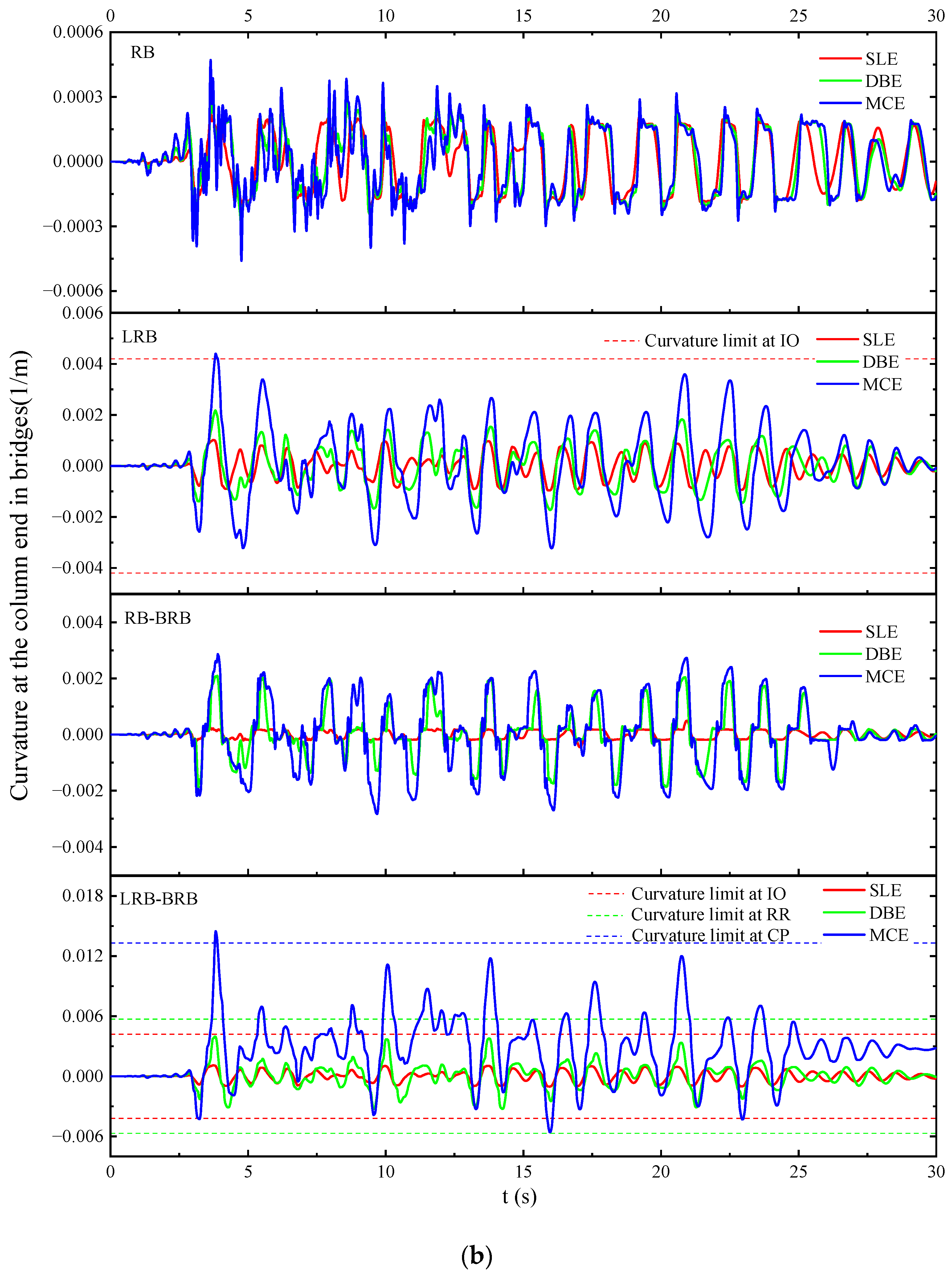
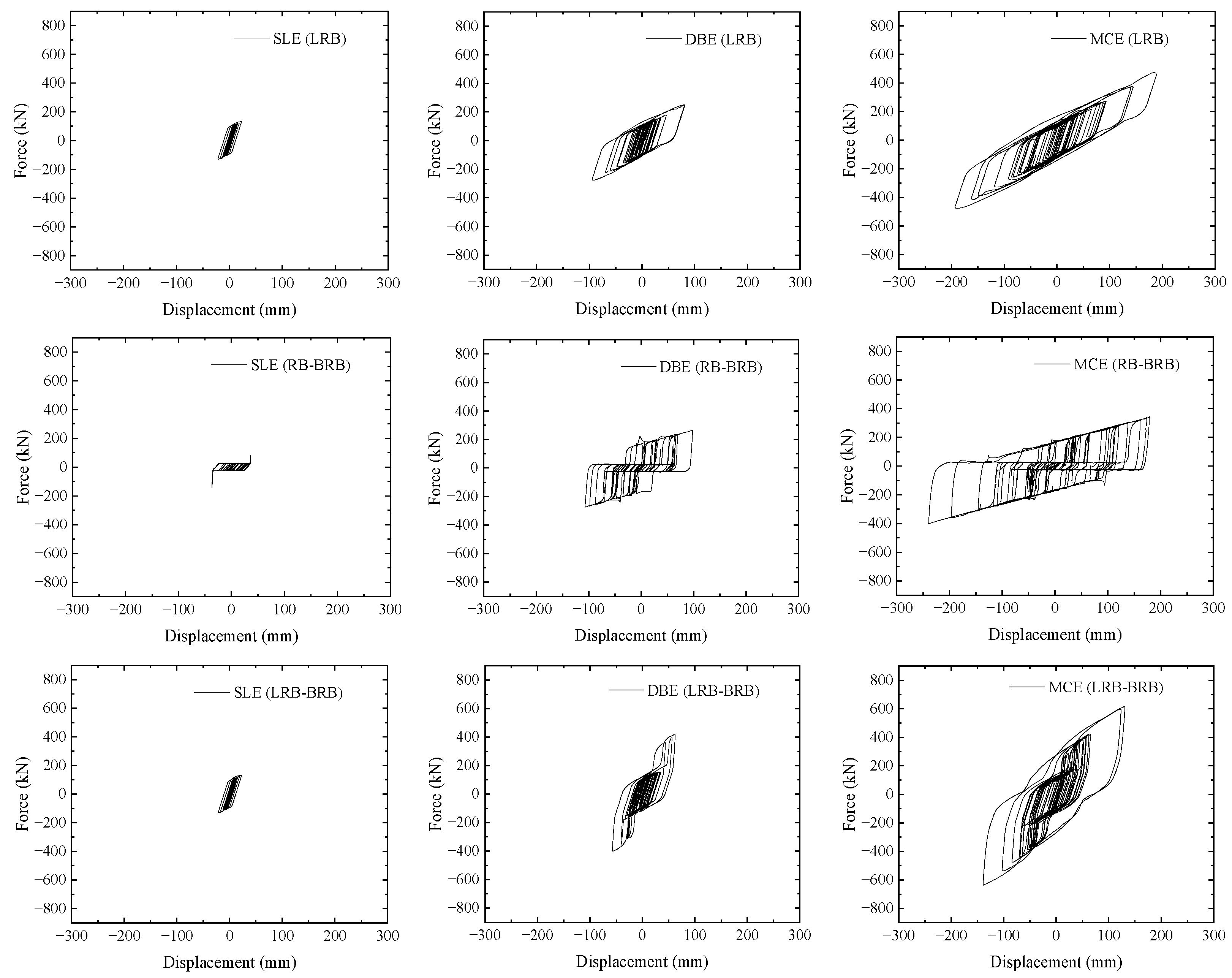
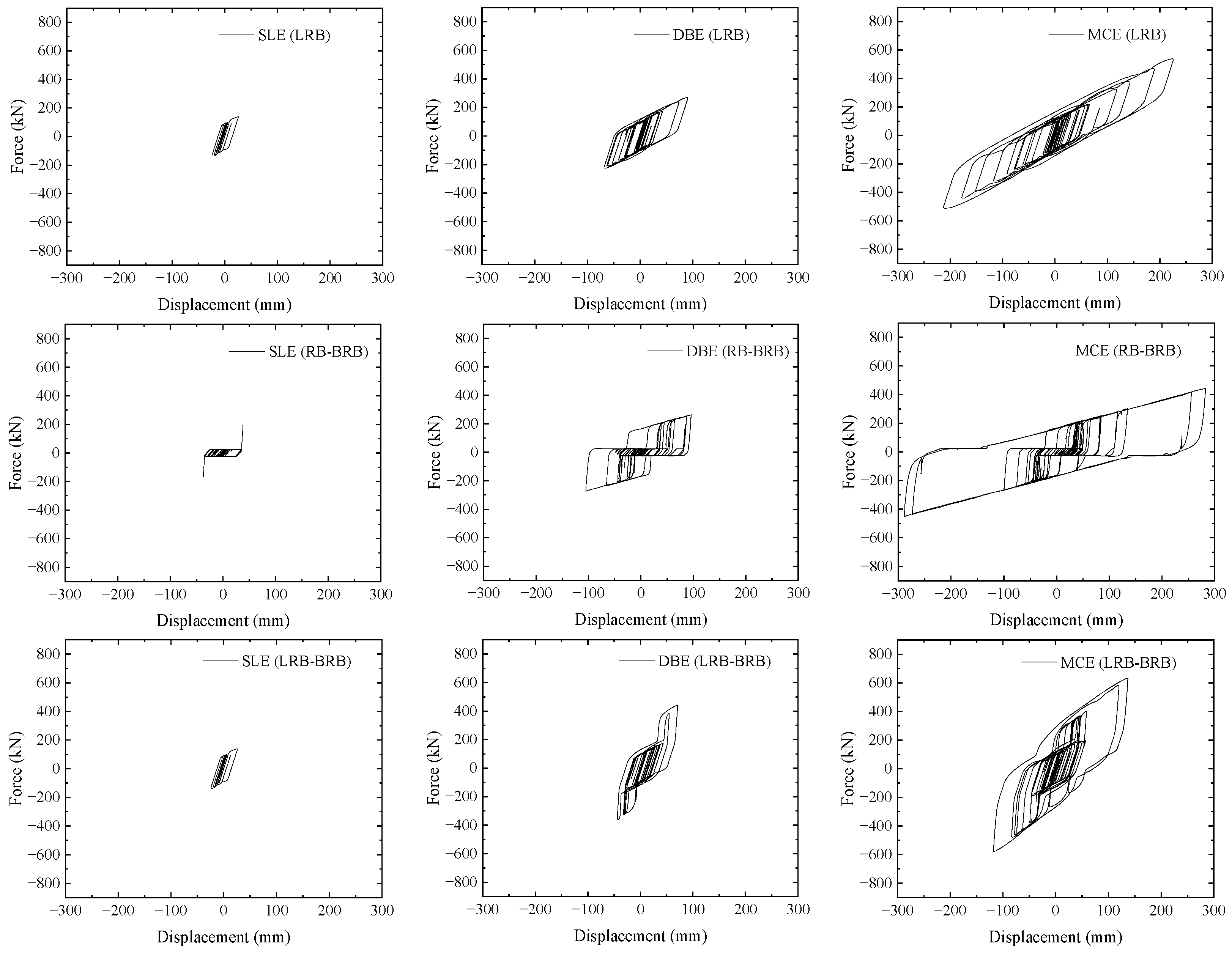
3.2. Seismic Analyses of the Isolated Bridges at Different Seismic Levels

For the bridge considered herein, with Y-shaped limbs and a single column, the bearing shear deformation is the primary structural response used to predict the risk of deck unseating, while the base curvature is the key damage indicator for the collapse of piers. The seismic analyses of the bridges with different isolation systems were performed through NTHAs on the OpenSess platform. In each simulation, the far-fault earthquake record FF1 was chosen as the seismic excitation and spectrally matched to the SLE, DBE, and MCE levels as described above. Each pier was assumed to vibrate in the first mode with a damping ratio of 5 %. Figure 8a shows the time histories of the shear deformations in models with different isolation systems under the FF1 ground motion. Different shear limits were set according to the design criteria listed in Table 6 for different earthquake intensities. It is evident that the shear deformations for all isolation systems are within their corresponding shear limits at the SLE. At the DBE, the shear deformation responses in the models with different isolation systems are all within their shear limit, except for some shear response peaks in the time history of the prototype bridge with RB. At the MCE, some shear deformation peaks in bridges with RB and RB–BRB are larger than the corresponding shear limit at collapse. This indicates that with RB or RB–BRB isolation systems, the bridge in question cannot achieve the CP performance under the MCE intensities. For bridges with LRB, all the responses except for a single peak are within the shear limit at CP. However, this CP performance was achieved well in the model with LRB–BRB with all the shear peaks below their corresponding shear limits. This demonstrates that the LRB–BRB is the most effective isolation system for mitigating the shear deformation of the bearing.
Figure 8b shows the time histories of the base curvature in bridges with different isolation systems under the FF1 ground motion. The different curvature limits were calculated from the moment–curvature analyses for the different performance objectives, as listed in Table 6. It is evident that all curvature responses are within the design criteria corresponding to the desired performances, except for a single peak in the bridge with LRB–BRB at the MCE. Moreover, a residual base curvature after the earthquake event was observed in this case, indicating the permanent damage to the pier bases under the MCE intensity. Under the large earthquakes, the LRB–BRB can dissipate more energy than other isolation systems; however, under the moderate earthquakes, the LRB–BRB will transfer the larger seismic force to the pier underneath. Therefore, the energy-based preliminary design may not achieve all the target performances at the corresponding seismic levels.
Figure 9 shows the hysteretic curves of the ESDF models under the FF1 ground motions spectrally matched to the SLE, DBE, and MCE intensities. With the increase in the earthquake intensity, the energy dissipation characterized as the area of the utmost hysteresis increases significantly for the models with LRB, RB–BRB, and LRB–BRB. At the SLE, the input energy is small and can be readily dissipated by the friction of the rubber bearings, as shown in the mode with RB–BRB, or the yielding of the lead rubber bearings, as shown in the models with LRB and LRB–BRB.
At the DBE, the input energy in the model with LRB is still dissipated by the lead rubber bearings, showing a similar but larger hysteresis as that at the SLE. However, for the bridge with RB–BRB and LRB–BRB, the input energy is dissipated in two phases: first, by the friction or yielding of the bearings (RB or LRB) and then by the yielding of BRBs. The hysteresis shows an evident pinching for the model with RB–BRB or with LRB–BRB, indicating a two-phase energy dissipation behavior. At the MCE level, a similar but larger two-phase energy dissipation is observed for models with RB–BRB and with LRB–BRB. It can be noted that the energies dissipated by RBs or LRBs are much smaller than that of BRBs. This implies that in the hybrid isolation system, the seismic energy is mostly dissipated by the stiffness and yielding of BRBs, but the gap spacing will determine the activation of the BRB and thereby influence the deck displacements. For example, the shear displacement in the bridge with RB–BRB is nearly 180 mm, exceeding the shear limit of RB (138 mm). The shear displacement for the bridge with LRB is 206 mm, which is much larger than 66 mm for the bridge with LRB–BRB.
The hysteretic curves of the models under the NF1 and PNF1 ground motions are illustrated in Figure 10 and Figure 11, respectively. Both ground motions are spectrally matched to the SLE, DBE, and MCE intensities. For each mode, the energy dissipation increases with the increase of the subjected earthquake intensities, similar to the pattern observed in the bridges subjected to the FF1 ground motions. It can also be noted that the shear displacement of the bridges subjected to the NF1 and PNF1 ground motions is slightly larger than that under the FF1 ground motions. For bridges under the PNF1 ground motion, the respective shear displacements for bridges with LRB, RB–BRB, and LRB–BRB are 226 mm, 289 mm, and 137 mm, respectively, which are slightly larger than the corresponding displacements for bridges under the FF1 ground motions. Particularly, the shear displacements in the LRB and RB–BRB are beyond the maximum displacement (200 mm) of the isolation system in bearing-supported bridges as suggested in the Chinese guidelines [37]. This means that the isolation system under the near-fault ground motions may not meet the performance demand at the MCE level. Similar pinching behaviors were also observed in the hysteresis loops for bridges with RB–BRB and LRB–BRB. This two-phase energy dissipation behavior suggests that the energy dissipation capacity can be exploited step-wisely by tuning the gap spacing to achieve multi-level target performances at different earthquake levels.

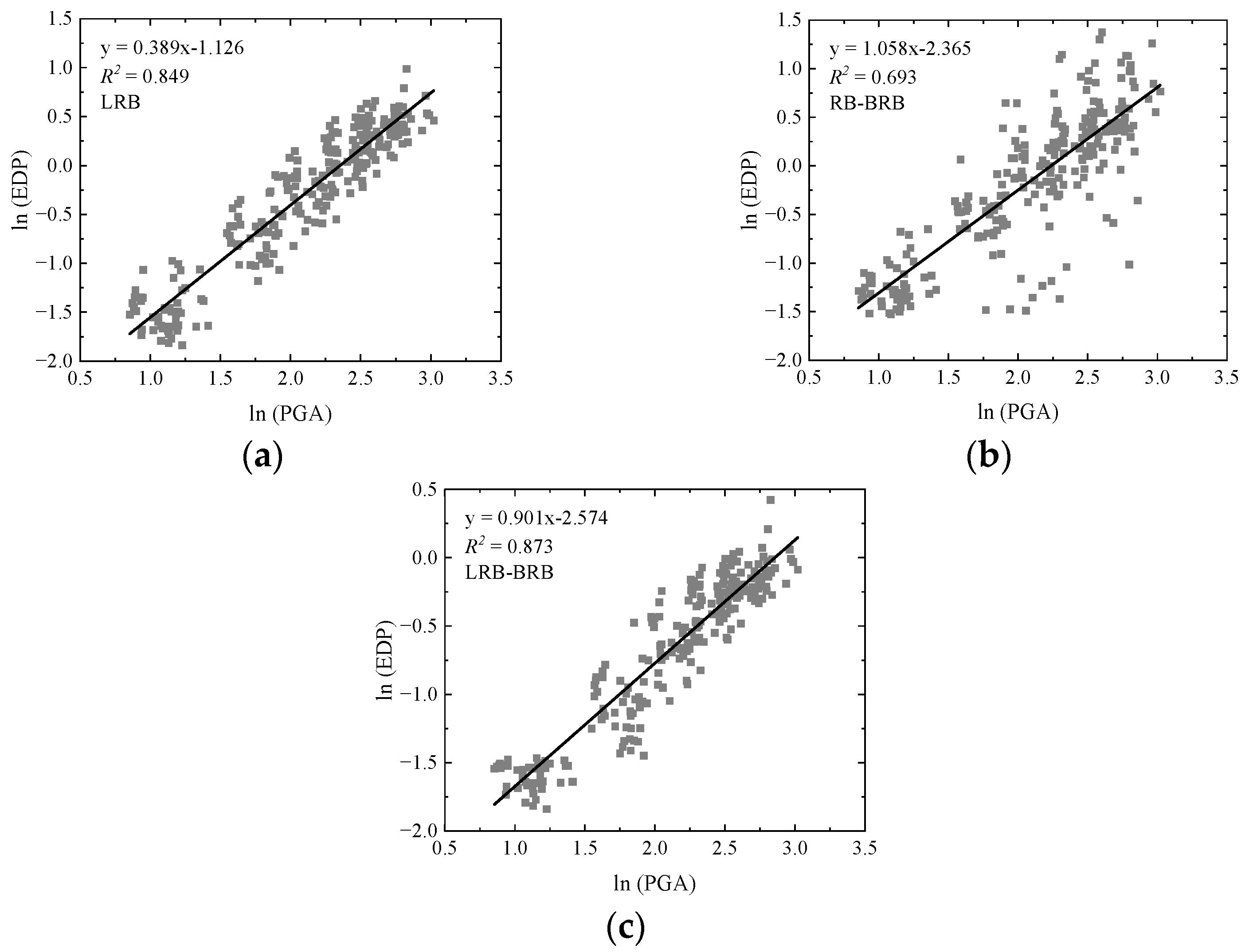
3.3. Optimal Seismic Design Based on the Fragility Analyses

To assess the seismic vulnerability of the bridges under different seismic hazards, fragility analyses were employed by calculating the conditional probability of exceeding the capacity for structural demands at different seismic intensity measures (IMs). A suite of seismic records, including 22 far-fault, 14 near-fault, and 14 pulse-like near-fault ground motions, were selected from the FEMA P695 [33] to consider three typical earthquake scenarios and scaled by the following set of factors, 0.5, 1.0, 1.5, 2.0, and 2.5, to represent different intensities. By performing probabilistic analyses on the responses calculated from the nonlinear dynamic analyses, the Probabilistic Seismic Demand Model (PSDM) was proposed by Shome et al. [39] to express the conditional probability of a structural seismic demand exceeding a limit state.
In PSDM, the probability of reaching a certain damage limit state (LS) is conditioned on a given earthquake IM and can be obtained using a lognormal distribution [40]:
P [ L S | I M ] = Φ [ ln ( E D P / S c ) β E D P | I M 2 + β c 2 ]
where Φ is the standard normal cumulative distribution function, Sc is the median, and βc is the logarithmic standard deviation of a structural capacity at a given damage state. By using the power model [41], the relationship between the Engineering Demand Parameter (EDP) and the selected intensity measure (IM) during a given earthquake can be expressed as:
EDP = a(IM)b   or   ln(EDP) = lna + bln(IM)
where a and b are the constant regression coefficients. The logarithmic standard deviation of the interested EDP conditioned upon a given IM, β E D P | I M , can be obtained by:
β E D P | I M = i = 1 n ( ln ( E D P ) ln ( a I M b ) ) 2 n 2
where n is the number of the NTHA simulations under the considered earthquakes.
By performing a set of NTHAs, the dynamic responses were calculated for the considered bridges subjected to the selected and scaled earthquakes. Based on the crucial responses, we constructed two critical damage indexes, such as the bearing shear strain and the base curvature ductility, as EDPs that can be readily obtained from the simulations. The damage probability can thus be calculated by checking the key damage indexes against their corresponding criteria, which were proposed in previous studies [22].
Based on the damage status exemplified in HAZUS [42], the criteria of the damage indexes (the median and dispersion) were defined based on the loss of capacity relative to the seismic demand. Accordingly, four damage limit states, namely slight, moderate, extensive, and complete, were determined for all the considered bridges. Table 9 shows the empirical medians and logarithmic standard deviations of two damage indexes available in past studies for bearing and pier at different limit states [22].
For bearing-supported bridges, piers and bearings are the primary components that determine the structural capacity and the failure of the bridge system. The bridges considered here will reach a specific damage state as either the piers or bearings reach their limit states. In this study, piers and bearings are assumed to operate in series to resist earthquake shakings without considering the uncertainty of the local damages [43]. Thus, the system fragility is within a range with lower and upper bounds given below [44]:
Max[P(Fbearing), P(Fpier)] ≤ P(Fsystem) ≤ 1 − [(1 − P(Fbearing)) (1 − P(Fpier))]
where P(Fbearing), P(Fpier), and P(Fsystem) are the failure probabilities of the bearing, the pier, and the overall bridge system, respectively. The lower bound indicates that the responses of the piers and the bearings in this bridge are completely correlated, while the upper bound means there is no correlation between them.
In this work, three types of isolated bridges were compared based on the fragility functions derived from the nonlinear dynamic analyses performed at different IMs. The peak ground acceleration (PGA) was selected as the IM in the probabilistic seismic demand analysis of each bridge [45]. By employing PSDM, we presented the logarithmic relations between the EDPs (the bearing shear strain and the base curvature ductility) and the IM (PGA) in three isolated bridges under the considered ground motions, as shown in Figure 12 and Figure 13, respectively. We noted that the coefficients of determination R2 for all the cases are larger than 0.6, indicating a good fitting of the linear regression model to evaluate the damage probability under the considered PGAs.
Figure 14 presents the fragility curves for the bearing shear strain in bridges with different isolation systems under the considered ground motions. It was observed that with the aid of the isolation systems, bearings will not fail under a PGA less than 0.6 g for each damage state. It was also noted that the effectiveness of the three isolation systems for mitigating the probability of damage increases from the slight to complete damage states. Among the three isolation systems, LRB–BRB is the most effective one in reducing the probability of damage to the bearings for all the damage states over the considered PGA range. Over the PGAs ranging from 0.0 g to 1.3 g, LRB is more effective than RB–BRB in reducing the bearing failure probability at all damage states.
Figure 15 presents the fragility curves for the base curvature ductility in the models with different isolation systems under the considered ground motions. It was observed that due to the implementation of the isolation systems, piers will not fail under a PGA less than 0.3 g for each damage state. However, for cases with a PGA larger than 0.6 g, the RB–BRB performs best followed by the LRB and the LRB–BRB. This distinct effectiveness among the three isolation systems can be explained by the different actions of their included BRBs. During the small earthquakes, the shear deformation of LRB is too small to close the gap spacing. In this case, the LRB–BRB acts similar to an individual LRB, which may dissipate more energy than an RB and thereby cause a smaller pier failure probability.
During large earthquakes, the bearing shear deformation becomes large enough to close the gap and yield the BRB. On one side, the early yielding of the BRB may dissipate more energy to prevent the failure of the bearings, consistent with the best effectiveness of the LRB–BRB in protecting bearings, as shown in Figure 14. On the other side, the installation of BRB will increase the shear stiffness of the isolation system and hence the shear force transferred to the piers underneath, resulting in the increased failure probability of the piers. As shown in Figure 15, the failure probability of the piers is the highest for the bridge with LRB–BRB, followed by the bridges with LRB and RB–BRB under the PGAs above 0.6 g. This demonstrates the contradiction of the structural fragility between the pier and bearing at large earthquakes, which can be explained by the competition between the larger demand for energy dissipation capacity and the lesser demand for stiffness in the design of the isolation system.
In the detailing design, the dimensions of the primary bridge components should be consistent with the energy-based preliminary design. This strategy is much more practical for the retrofitting practice where the as-built design is unchangeable. In this case, tuning the design parameters of the LRB–BRB isolation system, such as the stiffness and gap spacing, are convenient for design since this does not require changing the bridge components. For the bridge with LRB–BRB, the stiffness ratios (SR) of the BRBs to the piers were selected to be 1.0, 5.0, 10.0, 15.0, 20.0, and 25.0, while the gap spacings range from 15 mm to 150 mm for each selected SR. The fragility functions for the bearing shear strain and the base curvature ductility can thus be obtained from the 2100 fragility analyses.
Based on the fragility function, the median PGAs (earthquake IM) corresponding to the 50% failure probability of both responses were chosen to indicate their structural performances. Figure 16 and Figure 17 illustrate the median PGA as a function of SR and d for the bridge with LRB–BRB at different damage states. Generally, a higher median PGA means a better structural performance under a certain damage state. In this case, the two crucial responses are highly correlated but show opposite dependencies on the SR and d. For the bearing fragility curves, the median PGAs increase with the increase of the SR. This confirms that the bearing performance is improved by increasing the stiffness of the BRB. However, for the pier fragility curves, the median PGAs increase with the decrease of the SR monotonically at the moderate and extensive damage states, indicating that the performance of the pier is improved by decreasing the SR. However, under the slight and complete damage states, the median PGAs reach peaks at an SR of 5.0 and then decrease as the SR decreases to 1.0.
It is evident from Figure 16 that the median PGAs of the bearing fragility curves increase with the decrease of d for all SRs. However, regarding the pier fragility, the effect of d is correlated with that of SR, as seen in Figure 17. At the large SRs, the median PGAs increase with the increase of d; as the SRs decrease to 5.0, the median PGAs become nearly insensitive to d, particularly in the range from 15 mm to 100 mm.
As we have reported in Figure 8, the CP performance cannot be fully achieved in the preliminarily designed bridge with LRB–BRB under the MCE intensity. In the further design procedure, the seismic design of the bridge should be improved based on the previous parametric studies. For the more practical application, the dimensions of the preliminary design remained unchanged and only two design parameters, SR and d, of the hybrid isolation system, were modified to improve the seismic performances. An optimized isolation system with an SR of 5 and d of 75 mm was suggested according to Figure 17. This optimal design of the LRB–BRB considerably improves the structural performance of the pier without significantly impairing the performance of the bearing.
Figure 18 and Figure 19 show the response time histories in the bridge with the optimized LRB–BRB subjected to the FF1 and PNF1 ground motions, respectively. In each case, both the bearing shear deformation and the base curvature are reduced remarkably, compared with those in the preliminary design with the SR of 10 and the d of 35 mm, as illustrated in Figure 8. It was also observed that the bridge with the optimized LRB–BRB can achieve all the target performances under the code-specified multi-level FF1 earthquakes. Although the optimal design of the LRB–BRB is conducted under the PNF ground motions, it can also perform well under the FF ground motions. This implies that the optimized hybrid isolation system is insensitive to the seismic scenario.

4. Conclusions

This work studied the seismic performance in the case of a bridge (with Y-shaped piers) installed with hybrid isolation systems made of commercially available isolators, such as RBs, LRBs, and BRBs. By using the simplified EEDP, the preliminary designs of the bearing-supported bridges with gap-tunable BRBs were first proposed to meet the energy demands of designed earthquakes. Further, nonlinear time-history analyses of the designed bridges with LRB, RB–BRB, and LRB–BRB were performed to investigate the seismic responses and energy dissipation capacities of the hybrid isolation systems under the considered ground motions. Finally, an optimal seismic design based on the fragility analyses was proposed to achieve a better seismic performance based on the preliminary design. The following conclusions can be drawn:
(1)
A simplified energy-based seismic design of the bridge with the RB–BRB and LRB–BRB hybrid isolation systems was proposed based on the energy-conservation concept. This could provide a rational preliminary design for bearing-supported bridges with hybrid isolation systems to meet the energy demands at different seismic intensities.
(2)
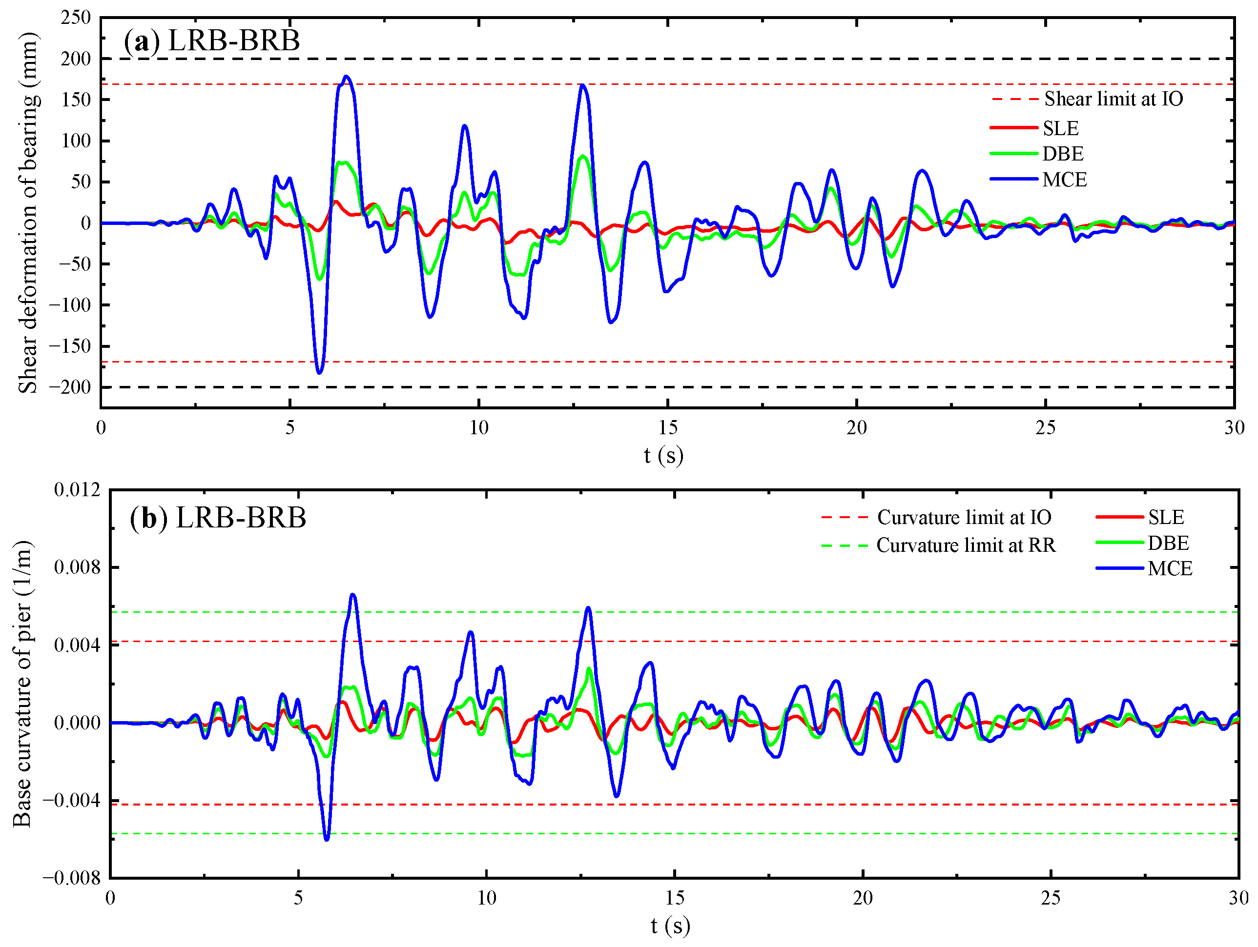
The energy-based preliminary design may not achieve all the target performances under the practical ground motions that are spectrally matched to the code-specified seismic levels. However, the hybrid RB–BRB and LRB–BRB isolation systems show a two-phase energy dissipation behavior.
(3)
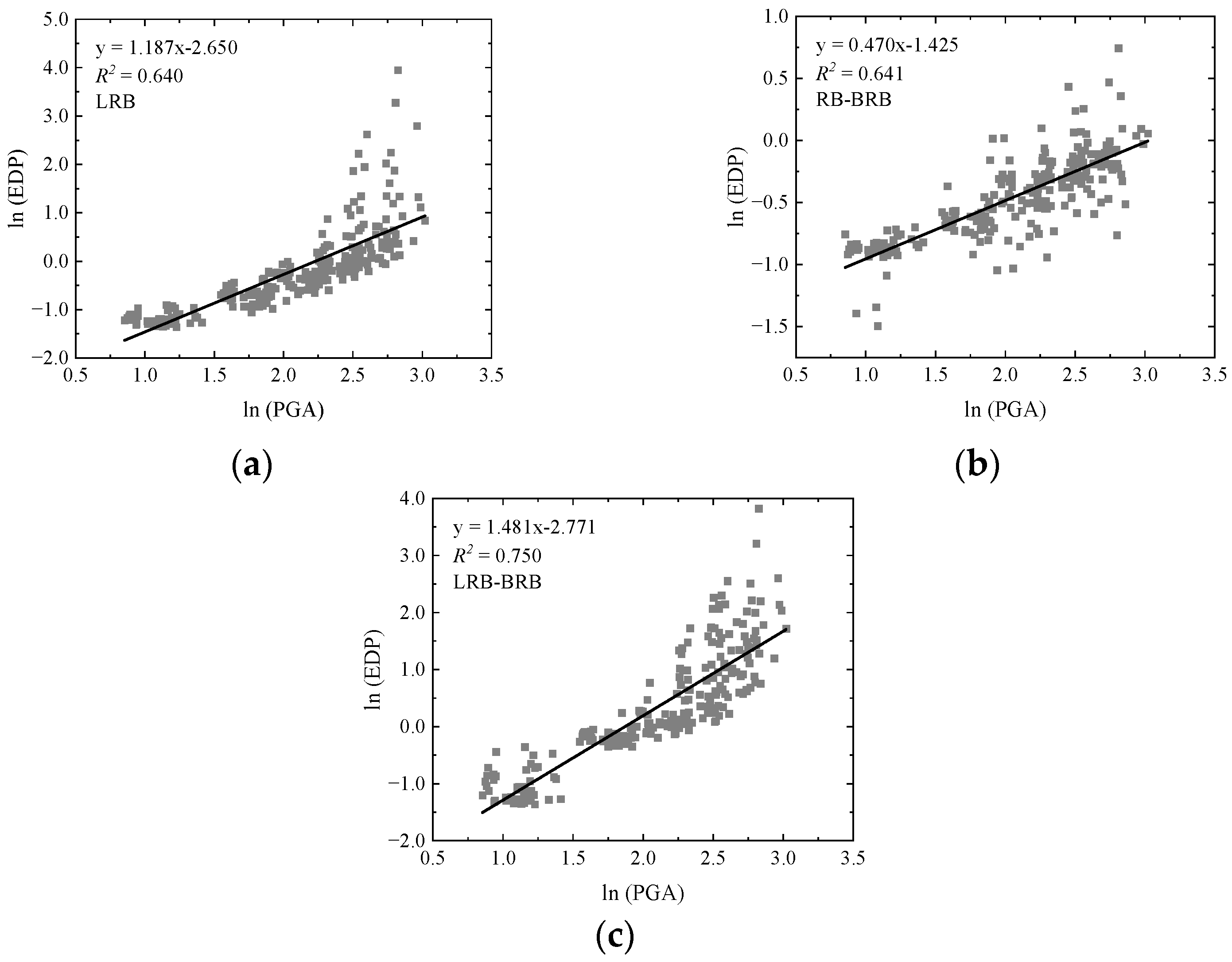
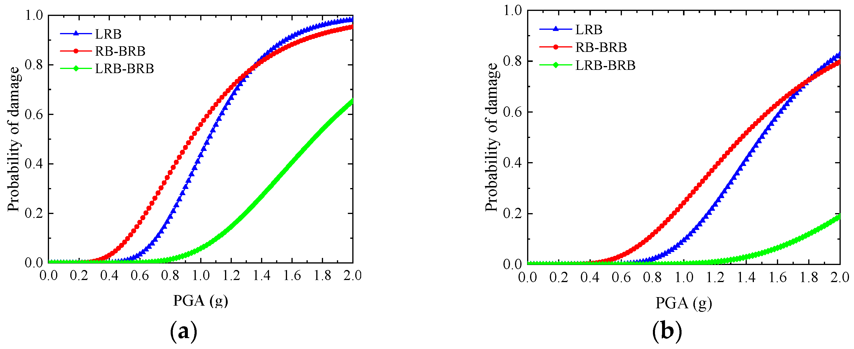
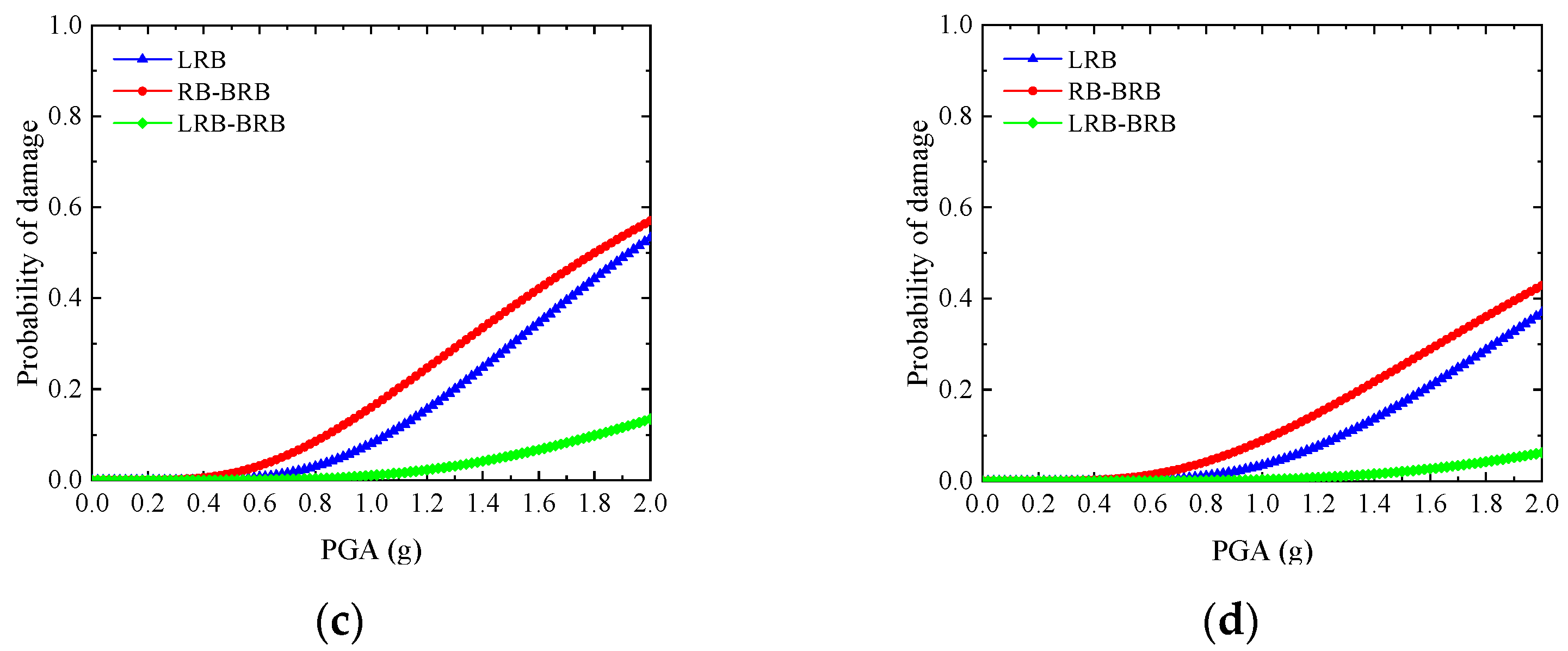
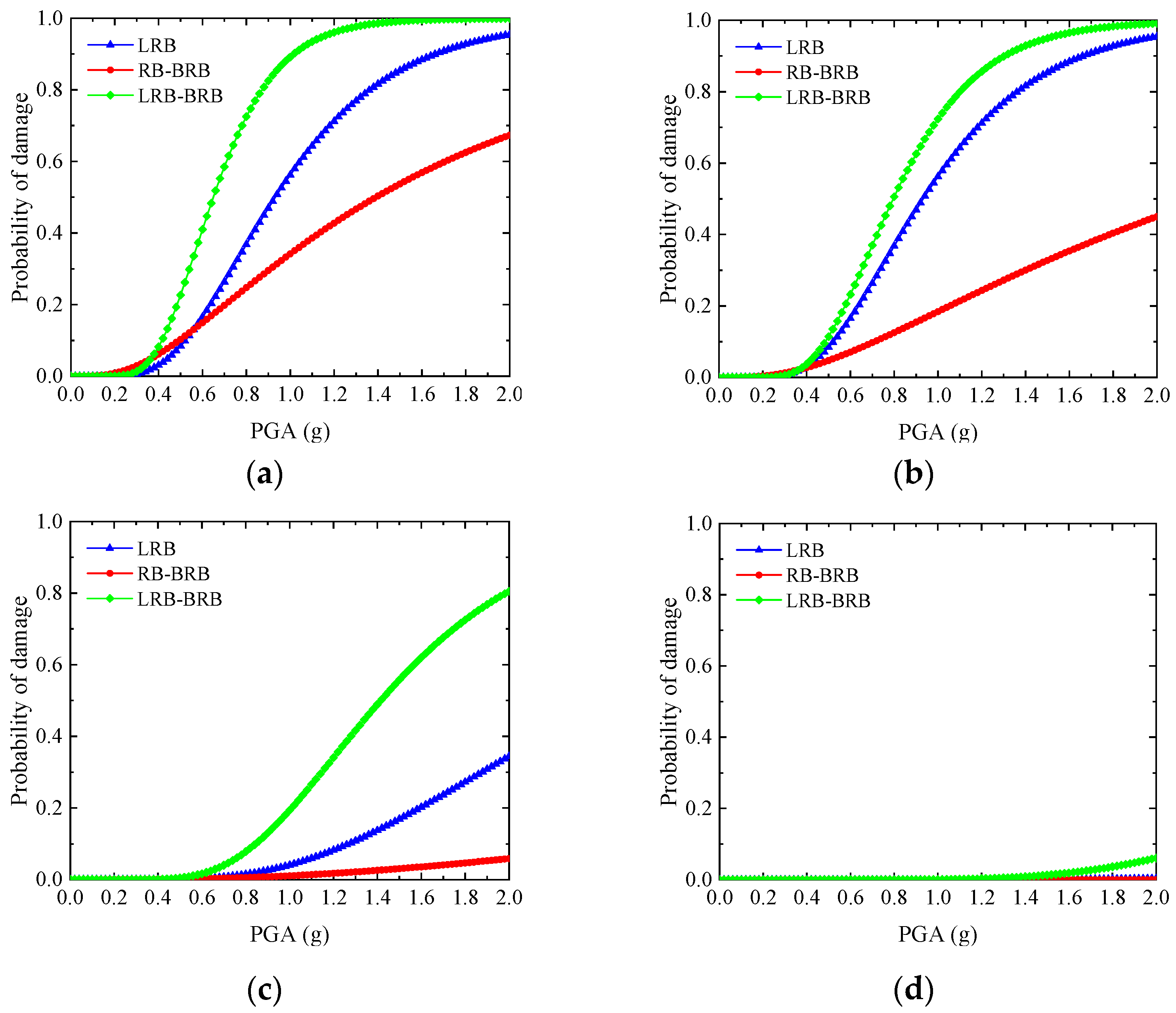
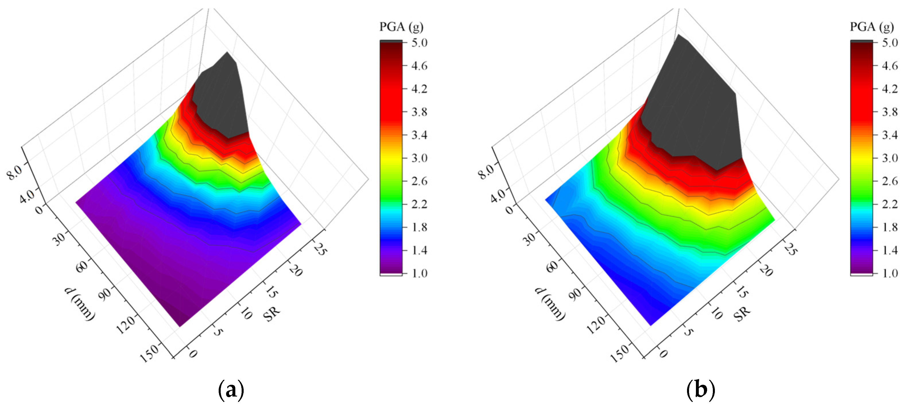
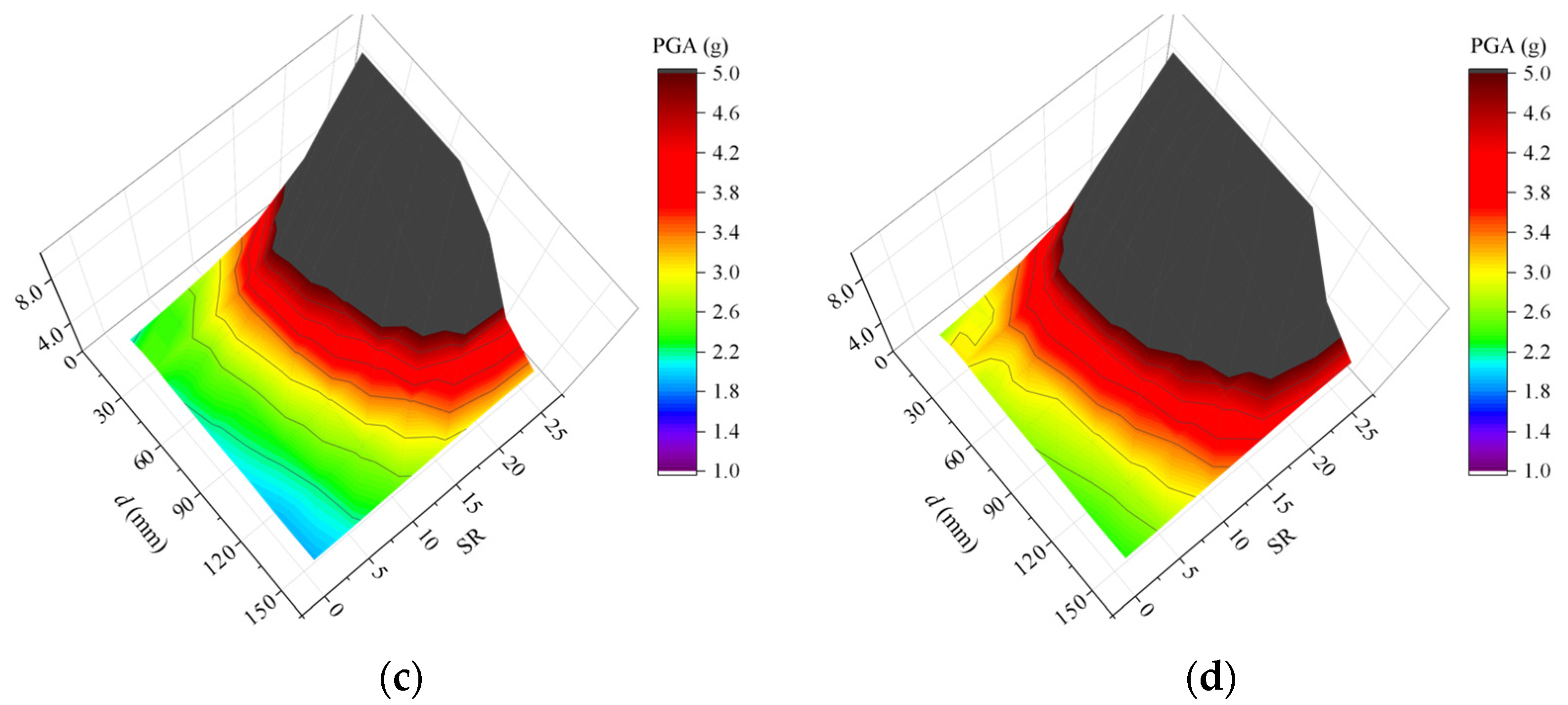
The fragility curves for the bearing shear strain and base curvature ductility show different dependencies on the SR and d at different damage states. The seismic performance of the bridge system can be adjusted by considering the fragilities of the bearing and pier simultaneously, which is dependent on the stiffness ratio (SR) of the BRB to the pier and the gap spacing (d).
(4)
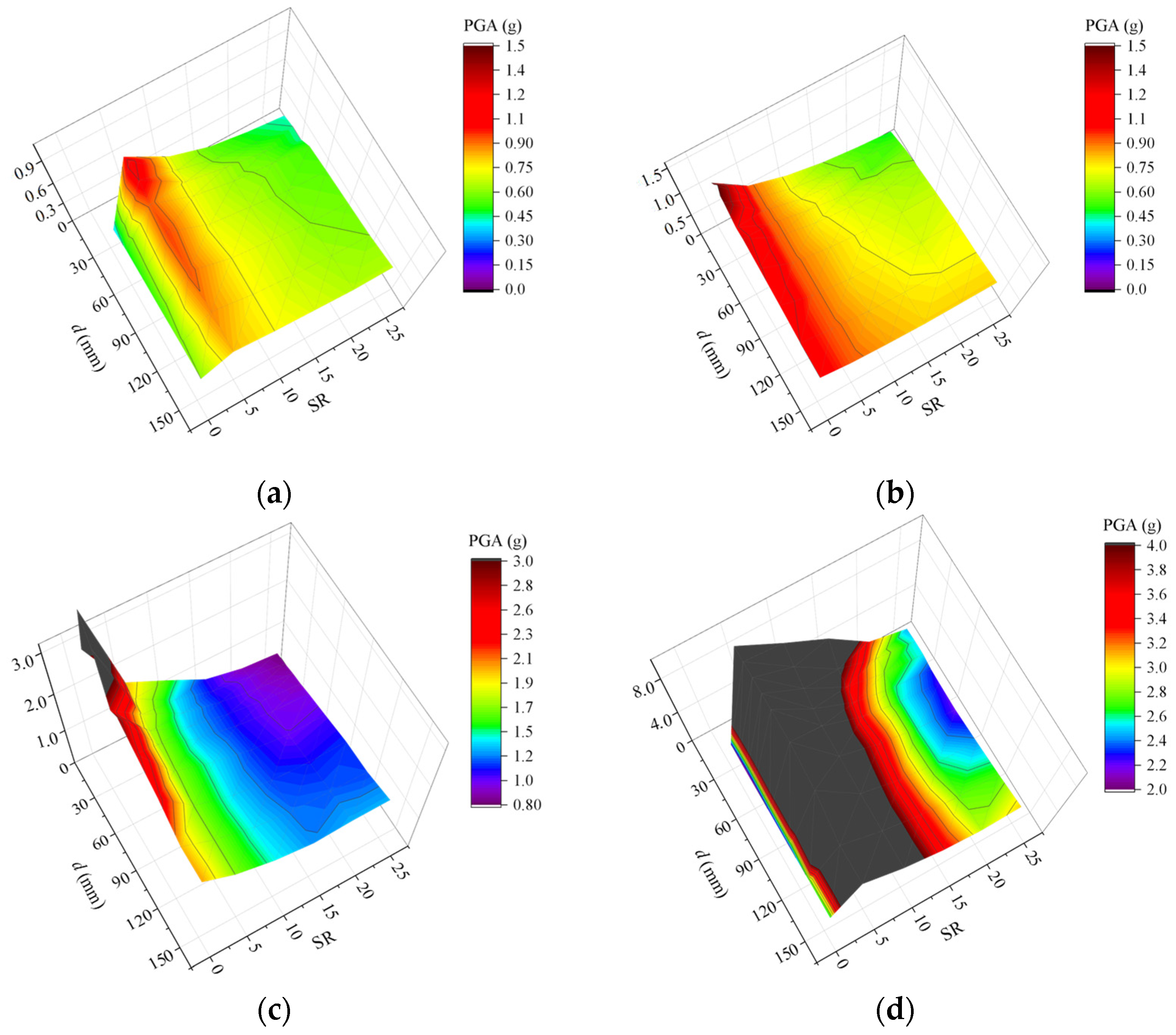
Two crucial design parameters, SR and d, can be tuned to reduce the failure probability of a bearing-supported bridge. Based on the fragility analyses, a performance-based seismic design of a bridge with LRB–BRB can be optimized and validated to achieve better performance by tuning the SR and d.
Furthermore, the design parameters (SR and d) can be readily adjusted for both new and existing bridges, which facilitates the application of this class of hybrid isolation system towards similar bearing-supported bridges to be designed or retrofitted.

Author Contributions

Q.L.: conceptualization, writing—review and editing, funding acquisition; Z.G.: investigation, writing—original draft preparation; S.Z.: investigation, software, methodology; C.W.: software, data curation; X.R.: writing—review and editing, validation; X.W.: writing—review and editing, project administration. All authors have read and agreed to the published version of the manuscript.

Funding

This research was funded by the National Natural Science Fund Committee of China (Grant No. 11632014, 51808444), Scientific Research Program of Shanxi Provincial Education Department (18JK0502), State Key Laboratory for Strength and Vibration of Mechanical Structure open Foundation (Grant No. SV2018-KF-35), Startup Foundation of XUST (Grant No. 2018YQ2-05).

Institutional Review Board Statement

Not applicable.

Informed Consent Statement

Not applicable.

Data Availability Statement

Some data or models used during the study are available from the corresponding author by request.

Conflicts of Interest

The authors declare no conflict of interest.

References

  1. Hashimoto, S.; Fujino, Y.; Abe, M. Damage analysis of Hanshin expressway viaducts during 1995 Kobe earthquake. II: Damage mode of single reinforced concrete piers. J. Bridge Eng. 2005, 10, 54–60. [Google Scholar] [CrossRef]
  2. Han, Q.; Du, X.; Liu, J.; Li, Z.; Li, L.; Zhao, J. Seismic damage of highway bridges during the 2008 Wenchuan earthquake. Earthq. Eng. Eng. Vib. 2009, 8, 263–273. [Google Scholar] [CrossRef]
  3. Schanack, F.; Valdebenito, G.; Alvial, J. Seismic damage to bridges during the 27 February 2010 magnitude 8.8 Chile earthquake. Earthq. Spectra 2012, 28, 301–315. [Google Scholar] [CrossRef]
  4. Nagarajaiah, S.; Sun, X. Base-isolated FCC building: Impact response in Northridge earthquake. J. Struct. Eng.-ASCE 2001, 127, 1063–1075. [Google Scholar] [CrossRef] [Green Version]
  5. Filipov, E.T.; Fahnestock, L.A.; Steelman, J.S.; Hajjar, J.F.; LaFave, J.M. Evaluation of quasi-isolated seismic bridge behavior using nonlinear bearing models. Eng. Struct. 2013, 49, 168–181. [Google Scholar] [CrossRef]
  6. Zheng, W.; Wang, H.; Li, J.; Shen, H. Parametric study of superelastic-sliding LRB system for seismic response control of continuous bridges. J. Bridge Eng. 2020, 25, 04020062. [Google Scholar] [CrossRef]
  7. Shi, Q.X.; Wang, F.; Wang, P.; Chen, K. Experimental and numerical study of the seismic performance of an all-steel assembled Q195 low-yield buckling-restrained brace. Eng. Struct. 2018, 176, 481–499. [Google Scholar] [CrossRef]
  8. Kim, D.H.; Ju, Y.K.; Kim, M.H.; Kim, S.D. Wind-induced vibration control of tall buildings using hybrid buckling-restrained braces. Struct. Des. Tall Spec. Build. 2014, 23, 549–562. [Google Scholar] [CrossRef]
  9. Li, C.; Liu, Y.; Li, H.N. Fragility assessment and optimum design of a steel–concrete frame structure with hybrid energy-dissipated devices under multi-hazards of earthquake and wind. Eng. Struct. 2021, 245, 112878. [Google Scholar] [CrossRef]
  10. Marshall, J.D.; Charney, F.A. Seismic response of steel frame structures with hybrid passive control systems. Earthq. Eng. Struct. Dyn. 2012, 41, 715–733. [Google Scholar] [CrossRef]
  11. Dong, H.; Du, X.; Han, Q.; Hao, H.; Bi, K.; Wang, X. Performance of an innovative self-centering buckling restrained brace for mitigating seismic responses of bridge structures with double-column piers. Eng. Struct. 2017, 148, 47–62. [Google Scholar] [CrossRef]
  12. Chen, R.; Qiu, C.; Hao, D. Seismic response analysis of multi-story steel frames using BRB and SCB hybrid bracing system. Appl. Sci. 2019, 10, 284. [Google Scholar] [CrossRef] [Green Version]
  13. Priestley, M.J.N.; Calvi, G.M.; Kowalsky, M.J. Direct displacement-based seismic design of structures. J. Earthq. Eng. 2005, 9, 257–278. [Google Scholar]
  14. Xiang, N.; Alam, M.S. Displacement-based seismic design of bridge bents retrofitted with various bracing devices and their seismic fragility assessment under near-fault and far-field ground motions. Soil. Dyn. Earthq. Eng. 2019, 119, 75–90. [Google Scholar] [CrossRef]
  15. Calvi, G.M.; Kingsley, G.R. Displacement-based seismic design of multi-degree-of-freedom bridge structures. Earthq. Eng. Struct. Dyn. 1995, 24, 1247–1266. [Google Scholar] [CrossRef]
  16. Yang, T.Y.; Tung, D.P.; Li, Y. Equivalent energy design procedure for earthquake resilient fused structures. Earthq. Spectra 2018, 34, 795–815. [Google Scholar] [CrossRef]
  17. Sadeghi, M.A.; Yang, T.Y.; Bagatini-Cachuço, F.; Pan, S. Seismic design and performance evaluation of controlled rocking dual-fused bridge system. Eng. Struct. 2020, 212, 110467. [Google Scholar] [CrossRef]
  18. Guo, W.; Du, Q.; Huang, Z.; Gou, H.; Xie, X.; Li, Y. An improved equivalent energy-based design procedure for seismic isolation system of simply supported bridge in China’s high-speed railway. Soil Dyn. Earthq. Eng. 2020, 134, 106161. [Google Scholar] [CrossRef]
  19. Takewaki, I.; Yoshitomi, S.; Uetani, K.; Tsuji, M. Non-monotonic optimal damper placement via steepest direction search. Earthq. Eng. Struct. Dyn. 1999, 28, 655–670. [Google Scholar] [CrossRef]
  20. Ozbulut, O.E.; Roschke, P.N.; Lin, P.Y.; Loh, C.H. GA-based optimum design of a shape memory alloy device for seismic response mitigation. Smart Mater. Struct. 2010, 19, 065004. [Google Scholar] [CrossRef]
  21. Pang, Y.; Sun, Y.; Zhong, J. Resilience-based performance and design of SMA/sliding bearing isolation system for highway bridges. Bull. Earthq. Eng. 2021, 19, 6187–6211. [Google Scholar] [CrossRef]
  22. Zhang, J.; Huo, Y. Evaluating effectiveness and optimum design of isolation devices for highway bridges using the fragility function method. Eng. Struct. 2009, 31, 1648–1660. [Google Scholar] [CrossRef]
  23. Montazeri, M.; Amiri, G.G.; Namiranian, P. Seismic fragility and cost-benefit analysis of a conventional bridge with retrofit implements. Soil Dyn. Earthq. Eng. 2021, 141, 106456. [Google Scholar] [CrossRef]
  24. McKenna, F.; Scott, M.H.; Fenves, G.L. Nonlinear finite-element analysis software architecture using object composition. J. Comput. Civ. Eng. 2010, 24, 95–107. [Google Scholar] [CrossRef]
  25. Filippou, F.C.; Popov, E.P.; Bertero, V.V. Effects of Bond Deterioration on Hysteretic Behavior of Reinforced Concrete Joints; Earthquake Engineering Research Center, University of California: Berkeley, CA, USA, 1983. [Google Scholar]
  26. Scott, B.D.; Park, R.; Priestley, M.J.N. Stress-strain behavior of concrete confined by overlapping hoops at low and high strain rates. J. Proc. 1982, 79, 13–27. [Google Scholar]
  27. Susantha, K.A.S.; Ge, H.; Usami, T. Uniaxial stress–strain relationship of concrete confined by various shaped steel tubes. Eng. Struct. 2001, 23, 1331–1347. [Google Scholar] [CrossRef]
  28. CCCC Highway Consultants Co., Ltd. Series of Elastomeric Pad Bearings for Highway Bridges (JTJ 663-2006); People’s Communications Publishing: Beijing, China, 2007. [Google Scholar]
  29. Liu, Q.; Zhu, S.; Yu, W.; Wu, X.; Song, F.; Ren, X. Ground motion frequency insensitivity of bearing-supported pedestrian bridge with viscous dampers. KSCE J. Civ. Eng. 2021, 25, 2662–2673. [Google Scholar] [CrossRef]
  30. Anand, V.; Kumar, S.R.S. Seismic soil-structure interaction: A state-of-the-art review. Structures 2018, 16, 317–326. [Google Scholar] [CrossRef]
  31. Mylonakis, G.; Gazetas, G. Seismic soil-structure interaction: Beneficial or detrimental? J. Earthq. Eng. 2000, 4, 377–401. [Google Scholar] [CrossRef]
  32. Badry, P.; Satyam, N. Seismic soil structure interaction analysis for asymmetrical buildings supported on piled raft for the 2015 Nepal earthquake. J. Asian Earth Sci. 2017, 133, 102–113. [Google Scholar] [CrossRef]
  33. FEMA. Quantification of Building Seismic Performance Factors, in FEMA P695; Applied Technology Council Federal Emergency Management Agency: Washington, DC, USA, 2009. [Google Scholar]
  34. PEER. Pacific Earthquake Engineering Research Center-Strong Ground Motion Database; University of California, Berkeley: Berkeley, CA, USA, 2017. [Google Scholar]
  35. Al, A.L.; Abrahamson, N. An improved method for nonstationary spectral matching. Earthq. Spectra 2010, 26, 601–617. [Google Scholar]
  36. Yang, Y.; Lu, H.; Tan, X.; Chai, H.K.; Wang, R.; Zhang, Y. Fundamental mode shape estimation and element stiffness evaluation of girder bridges by using passing tractor-trailers. Mech. Syst. Signal. Proc. 2022, 169, 108746. [Google Scholar] [CrossRef]
  37. Ministry of Housing and Urban-Rural Development of the People’s Republic of China. Code for Seismic Design of Highways and Bridges (JTG/T2231-2020); China Architecture & Building Press: Beijing, China, 2010. [Google Scholar]
  38. Chadwell, C.B.; Imbsen, R.A. XTRACT: A Tool for Axial Force—Ultimate Curvature Interactions. In Structures 2004: Building on the Past, Securing the Future; American Society of Civil Engineers: Reston, VA, USA, 2004. [Google Scholar]
  39. Shome, N.; Cornell, C.A.; Bazzurro, P.; Carballo, J.E. Earthquakes, records, and nonlinear responses. Earthq. Spectra 1998, 14, 469–500. [Google Scholar] [CrossRef]
  40. Nielson, B.G. Analytical Fragility Curves for Highway Bridges in Moderate Seismic Zones; Georgia Institute of Technology: Atlanta, GA, USA, 2005. [Google Scholar]
  41. Cornell, C.A.; Jalayer, F.; Hamburger, R.O.; Foutch, D.A. Probabilistic basis for 2000 SAC federal emergency management agency steel moment frame guidelines. J. Struct. Eng. 2002, 128, 526–533. [Google Scholar] [CrossRef] [Green Version]
  42. Department of Homeland Security Federal Emergency Management Agency. Multi-Hazard Loss Estimation Methodology: Earthquake Model; in HAZUS-MH MR5; Federal Emergency Management Agency: Washington, DC, USA, 2011. [Google Scholar]
  43. Yang, Y.; Ling, Y.; Tan, X.; Wang, S.; Wang, R. Damage identification of frame structure based on approximate Metropolis–Hastings algorithm and probability density evolution method. Int. J. Struct. Stab. Dyn. 2022, 22, 2240014. [Google Scholar] [CrossRef]
  44. Nielson, B.G.; DesRoches, R. Seismic fragility methodology for highway bridges using a component level approach. Earthq. Eng. Struct. Dyn. 2007, 36, 823–839. [Google Scholar] [CrossRef]
  45. Padgett, J.E.; Nielson, B.G.; DesRoches, R. Selection of optimal intensity measures in probabilistic seismic demand models of highway bridge portfolios. Earthq. Eng. Struct. Dyn. 2008, 37, 711–725. [Google Scholar] [CrossRef]
Figure 1. (a) A three-span continuous prototype bridge with Y-shaped piers. (b) The typical Y-shaped pier in the bearing-supported bridge implemented with BRBs. (c) The finite element model for the typical pier with hybrid isolation system.
Symmetry 14 01373 g001
Figure 2. The typical force–displacement curve of an LRB.
Symmetry 14 01373 g002
Figure 3. The typical hysteretic curve of a BRB under cyclic loading.
Symmetry 14 01373 g003
Figure 4. The schematic depiction of an RB–BRB or LRB–BRB isolation system.
Symmetry 14 01373 g004
Figure 5. Force–displacement relationships of the (a) RB–BRB and (b) LRB–BRB isolation systems.
Symmetry 14 01373 g005
Figure 6. Target response spectra compared with response spectra of the selected individual ground motions at different earthquake hazard levels.
Symmetry 14 01373 g006
Figure 7. Seismic demand curves and force–displacement response for the ESDF models with (a) RB–BRB or (b) LRB–BRB isolation systems at different seismic hazard levels.
Symmetry 14 01373 g007
Figure 8. Time histories for (a) bearing shear deformation and (b) base curvature in bridges with RB, LRB, RB–BRB, and LRB–BRB subjected to the FF1 ground motion.
Symmetry 14 01373 g008aSymmetry 14 01373 g008b
Figure 9. Hysteretic curves of the isolated bridges under the far-fault ground motion (FF1) with different intensities.
Symmetry 14 01373 g009
Figure 10. Hysteretic curves of the isolated bridges under the near-fault ground motion (NF1) with different intensities.
Symmetry 14 01373 g010
Figure 11. Hysteretic curves of the isolated bridges under the pulse-like near-fault ground motion (PNF1) with different intensities.
Symmetry 14 01373 g011
Figure 12. Bearing shear strain (as EDP) in bridges with (a) LRB, (b) RB–BRB, and (c) LRB–BRB as a function of PGA (as IM).
Symmetry 14 01373 g012
Figure 13. Base curvature ductility (as EDP) in bridges with (a) LRB, (b) RB–BRB, and (c) LRB–BRB as a function of PGA (as IM).
Symmetry 14 01373 g013
Figure 14. Fragility curves for the shear strain of the bearings in bridges with different isolations at limit state: (a) slight; (b) moderate; (c) extensive; (d) complete.
Symmetry 14 01373 g014aSymmetry 14 01373 g014b
Figure 15. Fragility curves for the base curvature ductility in bridges with different isolations at limit state: (a) slight; (b) moderate; (c) extensive; (d) complete.
Symmetry 14 01373 g015
Figure 16. Effects of SR and d on the median IMs of bearing fragility curves for the bridge with LRB–BRB at different damage states: (a) slight; (b) moderate; (c) extensive; (d) complete.
Symmetry 14 01373 g016aSymmetry 14 01373 g016b
Figure 17. Effects of SR and d on the median IMs of pier fragility curves for the bridge with LRB–BRB at different damage states: (a) slight; (b) moderate; (c) extensive; (d) complete.
Symmetry 14 01373 g017
Figure 18. Time histories for (a) the bearing shear deformation and (b) the base curvature in the bridge with LRB–BRB subjected to the FF1 ground motion.
Symmetry 14 01373 g018
Figure 19. Time histories for (a) the bearing shear deformation and (b) the base curvature in the bridge with LRB–BRB subjected to the PNF1 ground motion.
Symmetry 14 01373 g019
Table 1. Initial mechanical parameters of the typical isolation systems.
Isolation
System
RBLRBBRBGap
Shear
Stiffness
(kN/m)
Shear Stiffness
(kN/m)
Post-Yielding
Stiffness
(kN/m)
Yielding
Strength
(kN/m)
Steel Core Area (mm2)d (mm)
RB2185
LRB 62001000
RB–BRB2185 18550035
LRB–BRB 6200100018550035
Table 2. Far-fault ground motion records.
No.EarthquakeYearStationMagnitudeVs_30 (m/s)PGA (g)PGV (cm/s)
FF1Northridge1994Beverly Hills6.69355.810.4263
FF2Northridge1994Canyon Country6.69325.60.4145
FF3Imperial
Valley
1979El Centro Array #116.53196.250.3642
FF4Kocaeli,
Turkey
1999Duzce7.52760.3159
FF5Landers1992Yermo Fire
Station
7.33540.2452
FF6Chi-Chi,
Taiwan
1999CHY1017.62590.35115
FF7Friuli, Italy1976Tolmezzo6.54250.3531
Table 3. Near-fault ground motion records.
No.EarthquakeYearStationMagnitudeVs_30 (m/s)PGA (g)PGV (cm/s)
NF1Imperial Valley-061979Chihuahua6.53242.050.2830.5
NF2Loma Prieta1989BRAN6.93476.540.6455.9
NF3Cape Mendocino1992Cape Mendocino7.05141.43119.5
NF4Northridge-011994LA-Sepulveda VA6.73800.7370.1
NF5Kocaeli, Turkey1999Yarimca7.52970.3173
NF6Chi-Chi, Taiwan1999TCU0847.65531.16115.1
NF7Denali, Alaska2002TAPS Pump Sta. #107.95530.33126.4
Table 4. Pulse-like near-fault ground motion records.
No.EarthquakeYearStationMagnitudeVs_30 (m/s)PGA (g)PGV (cm/s)
PNF1Irpinia, Italy-011980Sturno6.93820.3145.5
PNF2Erzican, Turkey1992Erzincan6.69352.050.4995.5
PNF3Landers1992Lucerne7.36850.79140.3
PNF4Northridge-011994Rinaldi Receiving Sta6.72820.87167.3
PNF5Northridge-011994Sylmar-Olive View6.74410.73122.8
PNF6Kocaeli, Turkey1999Izmit7.58110.2229.8
PNF7Duzce, Turkey1999Duzce7.12760.5279.3
Table 5. Periods of the first three modes for bridges with different isolation systems.
Isolation SystemT1 (s)T2 (s)T3 (s)
RB1.26021.18790.9304
LRB0.97710.86240.7146
RB–BRB1.26031.18870.9304
LRB–BRB0.97700.86120.7146
Table 6. Design criteria to target performance objectives for bridges under the corresponding earthquake intensity.
Earthquake
Intensity
Performance
Objective
Bearing Shear StrainBase Curvature
Ductility
SLEIOγ < 100%µ < 1.000 (φ0 < φy)
DBERRγ < 150%µ < 1.357 (φ0 < φe)
MCECPγ < 200%µ < 3.167 (φ0 < φm)
Table 7. Mechanical parameters of steel tubes.
Steel TubesFy (kN)E0 (Pa)bR0R1R2
Limb & column3.55 × 1052.06 × 10110.01180.9250.15
Here, Fy is the yield strength; E0 is the initial elastic modulus; b is the ratio of the post-yielding modulus to the initial elastic modulus; R0, R1, and R2 are the parameters that control the transition from elastic to plastic phases.
Table 8. Mechanical parameters of the confined concrete.
Bridge Componentfc′ (Pa)fcc′ (Pa)εccαfcc′ (Pa)εcuft (Pa)Ets (Pa)λ
Limb2.34 × 1074.20 × 1070.01008.40 × 1060.0254.20 × 1061.17 × 10100.1
Column2.34 × 1073.82 × 1070.00837.64 × 1060.0253.82 × 1061.17 × 10100.1
Here, fc′, ft, and Ets represent the compressive strength, the tensile strength, and the tension softening stiffness of the unconfined concrete, respectively; fcc′, αfcc′, εcc, and εcu are the compressive strength, the residual strength, the peak strain, and the ultimate strain of the confined concrete, respectively; λ is the ratio of the unloading modulus at crushing strain to the initial elastic modulus of the confined concrete.
Table 9. Damage indexes and corresponding limit states for bridge components.
Bridge
Component
Damage
Index
SlightModerateExtensiveComplete
ScβcScβcScβcScβc
BearingShear strain100%0.25150%0.25200%0.47250%0.47
PierBase curvature ductility1.0000.131.3570.273.1670.3214.0240.38
Publisher’s Note: MDPI stays neutral with regard to jurisdictional claims in published maps and institutional affiliations.

