
Method for Determining the Degree of Damage to the Stator Windings of an Induction Electric Motor with an Asymmetric Power System

 ,
,  , ,
, ,
Abstract
:1. Introduction
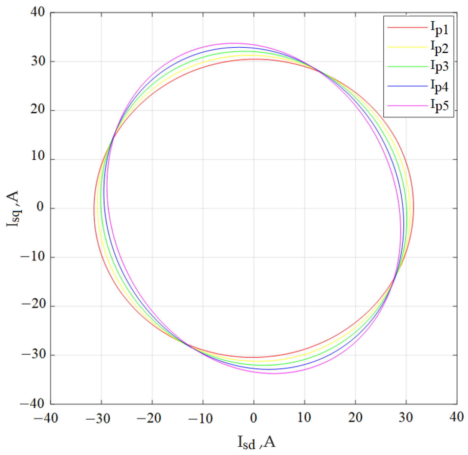
- The Park vector hodograph has been constructed under the condition that the supply voltage system is symmetrical for a different number of turns on one of the stator phases, the number of which was determined by taking into account the degree of damage to the winding (the number of closed turns). According to the hodograph diagrams of the Park vector, the values of the amplitudes of the stator phase currents and the angles of the phase shift between the current and voltage in each stator phase have been calculated. The determination of the amplitudes of the stator phase currents and the angles of the phase shift between the current and voltage have been carried out according to the time diagrams of the stator currents, after which the results have been compared;
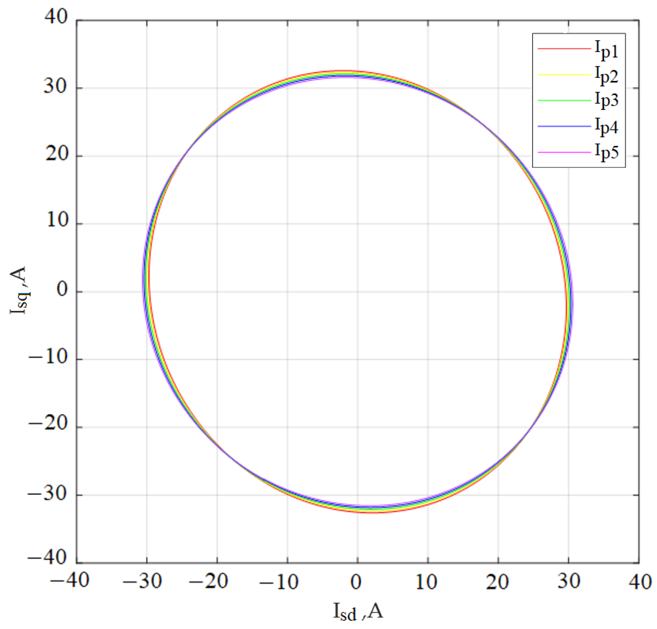
- The Park vector hodograph has been constructed under the condition of a fixed degree of damage to one of the phases of the stator winding and various values of deviations from the nominal phase supply voltage of one of the phases of the electric motor. According to the hodograph diagrams of the Park vector, the values of the amplitudes of the stator phase currents and the angles of the phase shift between the current and voltage in each stator phase have been calculated. The determination of the amplitudes of the phase currents of the stator and the angles of the phase shift between the current and voltage in each phase of the stator has been carried out according to the time diagrams of the stator currents, after which the results have been compared;
- The Park vector hodograph has been constructed under the condition of a fixed deviation from the nominal value of the phase supply voltage of one of the phases of the electric motor and a different number of turns of the winding of one of the stator phases, taking into account various degrees of interturn short circuit. According to the hodograph diagrams of the Park vector, the values of the amplitudes of the stator phase currents and the phase shift angles between the current and voltage in each stator phase have been calculated. The determination of the amplitudes and angles of the phase shift has been carried out according to the time diagrams of the stator currents, after which the results have been compared;
- The values of the amplitudes of the phase currents of the stator and the angles of the phase shift between current and voltage, obtained in Paragraphs 2 and 3, have been recalculated for the case of symmetry of the supply voltage system of the induction motor. Comparison of the received results with the results received in Point 1 has been carried out;
- An algorithm for determining the number of damaged turns of the stator winding of an induction motor has been proposed.
2. Materials and Methods
3. Determination of the Degree of Damage to the Stator Windings during Interturn Short Circuit
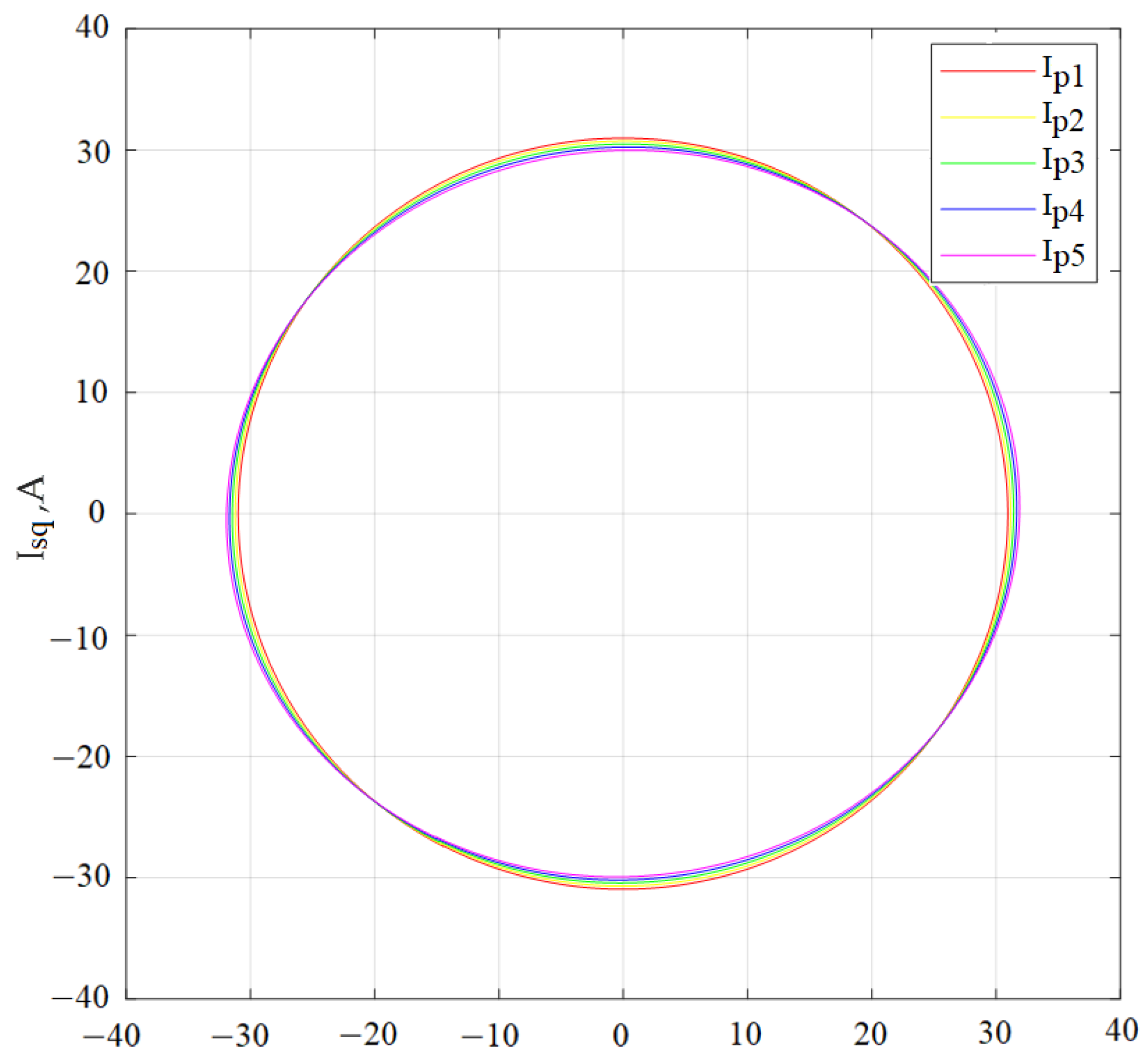
3.1. Determination of the Amplitude of the Stator Phase Currents and the Angles of the Phase Shift between Current and Voltage in Each Stator Phase with the Symmetry of the Supply Voltage System for a Different Number of Turns on One of the Stator Phases
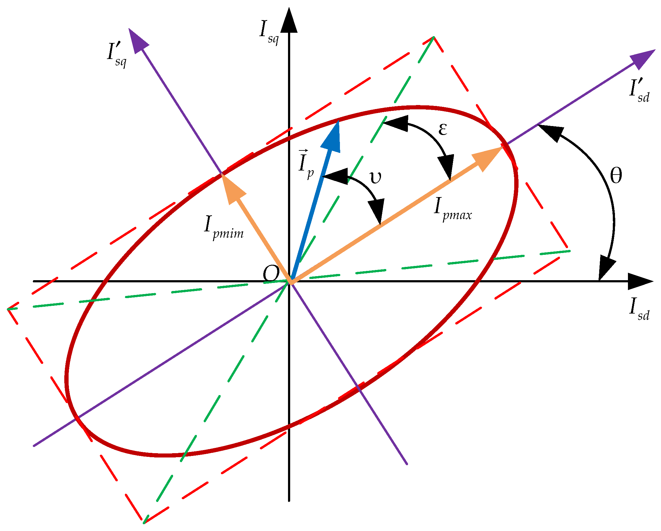
- θ—the orientation angle of the Park vector (ellipse): the angle between the OIsd axis and the main semi-axis of the ellipse);
- ε—the ellipticity angle: the angle between the main semi-axis of the ellipse and the diagonal of the rectangle closest to it;
- υ—the angle between the main semi-axis of the ellipse and the instantaneous position of the Park vector ;
- Ipmin,—the values of the Park vector when it coincides with the q axis;
- Ipmax—the values of the Park vector when it coincides with the d axis.
3.2. Determination of the Amplitude of the Stator Phase Currents and the Phase Shift Angles between Current and Voltage in Each Stator Phase for the Number of Turns on the Damaged Stator Phase with Asymmetry of the Supply Voltage System
3.3. Determination of the Amplitude of the Stator Phase Currents and the Angles of the Phase Shift between Current and Voltage in Each Stator Phase at a Fixed Degree of Asymmetry of the Supply Voltage System for a Different Number of Turns on One of the Stator Phases
3.4. Determination of the Amplitude of the Stator Phase Currents and the Phase Shift Angles between Current and Voltage in Each Stator Phase for Cases in Paragraphs 3.2 and 3.3 with a Symmetrical Supply Voltage System of an Induction Motor
3.5. Algorithm for Determining the Degree of Damage to the Stator Winding with an Asymmetric System of Electric Motor Supply Voltages
- According to the hodograph diagram of the Park vector, the following is determined: the value of the current Isd0 at Isq = 0, the value of the current Isq0, at Isd = 0, the maximum value of the Park vector Ipmax, the minimum value of the Park vector Ipmin, the value of the current Isd, at Ip = Ipmax, the value of the current Isq, at Ip = Ipmax;
- Calculate the ellipticity angle for an orthogonal–circular basis using Formula (6), calculation of the ellipticity angle for an orthogonal–elliptical basis by Formula (16) and calculation of the ellipse tilt angle by Formula (17).
- If the ellipse tilt angle is not equal to zero, which indicates a supply asymmetry, the values of the currents I′sd0 and I′sq0 are determined and recalculated for an orthogonal–circular basis according to Formulas (18)–(20);
- The calculation of the amplitudes and phase shift angles of the stator currents is carried out according to the Formulas (8), (10) and (11);
- According to the obtained amplitudes and phase shift angles of the stator currents for each phase, the number of damaged turns is calculated using the formulas:
4. Discussion
- When building a diagnostic system for an induction motor operating as part of a drive, the Park vector hodograph method has a higher accuracy than temperature methods;
- When building a diagnostic system for an induction motor operating as part of a drive, the supply voltage system may be asymmetrical. The asymmetry of the supply voltage system, in its effect on performance, has the same negative effect as the interturn short circuit of the stator windings, with similar processes occurring. First of all, the asymmetry of the rotating stator field leads to the occurrence of torque ripples on the motor shaft. Existing methods of vibration diagnostics do not allow for determining the causes of these pulsations. As shown in the paper, the Park vector hodograph method allows the solving of problems of this type.
- -
- -
- -
- The interturn short circuit on one of the stator phases was investigated. The mode of occurrence of an interturn short circuit at the same time during several phases remained unexplored;
- The influence of the non-sinusoidal nature of the supply voltage system was not taken into account.
- Development of a diagnostic system for an induction motor as part of a drive;
- Development of a diagnostic system for a drive with an induction motor powered by a three-phase autonomous voltage inverter.
5. Conclusions
Author Contributions
Funding
Institutional Review Board Statement
Informed Consent Statement
Data Availability Statement
Conflicts of Interest
References
- Turpak, S.M.; Taran, I.O.; Fomin, O.V.; Tretiak, O.O. Logistic technology to deliver raw material for metallurgical production. Sci. Bull. Natl. Min. Univ. 2018, 1, 162–169. Available online: http://nbuv.gov.ua/UJRN/Nvngu_2018_1_2 (accessed on 20 February 2022). [CrossRef]
- Klimenko, I.V.; Kalivoda, J.; Neduzha, L.O. Parameter Optimization of the Locomotive Running Gear. In Proceedings of the 22nd International Scientific Conference (Transport Means 2018), Trakai, Lithuania, 3–5 October 2018; pp. 1095–1098. Available online: http://eadnurt.diit.edu.ua/jspui/handle/123456789/10779 (accessed on 18 March 2022).
- Lunys, O.; Neduzha, L.O.; Tatarinova, V.A. Stability Research of the Main-Line Locomotive Movement. In Proceedings of the 22nd International Scientific Conference (Transport Means 2019), Palanga, Lithuania, 2–4 October 2019; pp. 1341–1345. Available online: http://eadnurt.diit.edu.ua/jspui/handle/123456789/11520 (accessed on 18 March 2022).
- Bondarenko, I.; Keršys, R.; Neduzha, L. Studying of Dynamic Parameters Impulse Impact of the Vehicle Taking into Account the Track Stiffness Variations. In Proceedings of the 25th International Conference (Transport Means 2021), Kaunas, Lithuania, 6–8 October 2021; Part II, pp. 684–689. [Google Scholar]
- Píštěk, V.; Kučera, P.; Fomin, O.; Lovska, A. Effective mistuning identification method of integrated bladed discs of marine engine turbochargers. J. Mar. Sci. Eng. 2020, 8, 379. [Google Scholar] [CrossRef]
- Fomin, O.; Lovska, A. Determination of dynamic loading of bearing structures of freight wagons with actual dimensions. East.-Eur. J. Enterp. Technol. 2021, 2, 6–14. [Google Scholar] [CrossRef]
- Bodnar, B.; Ochkasov, O.; Bodnar, E.; Hryshechkina, T.; Keršys, R. Safety performance analysis of the movement and operation of locomotives. In Proceedings of the 22nd International Scientific Conference (Transport Means 2018), Trakai, Lithuania, 3–5 October 2018; Kaunas University of Technology: Kaunas, Lithuania, 2018; Part II, pp. 839–843, Prieiga per internet. Available online: https://transportmeans.ktu.edu/wp-content/uploads/sites/307/2018/02/Transport-means-II-A4-2018-09-25.pdf (accessed on 20 April 2022).
- Leitner, B.; Rehak, D.; Kersys, R. The new procedure for identification of infrastructure elements significance in sub-sector railway transport. Commun.-Sci. Lett. Univ. Zilina 2018, 20, 41–48. [Google Scholar] [CrossRef]
- Ocampo-Martinez, C. Energy efficiency in discrete-manufacturing systems: Insights, trends, and control strategies. J. Manuf. Syst. 2019, 52, 131–145. [Google Scholar] [CrossRef] [Green Version]
- Fernandes, T.; Oliveira, E. Understanding consumers’ acceptance of automated technologies in service encounters: Drivers of digital voice assistants adoption. J. Bus. Res. 2021, 122, 180–191. [Google Scholar] [CrossRef]
- Yatsko, S.; Sidorenko, A.; Vashchenko, Y.; Liubarskyi, B.; Yeritsyan, B. Method to improve the efficiency of the traction rolling stock with onboard energy storage. Int. J. Renew. Energy Researc. 2019, 2, 1–11. Available online: https://www.ijrer.org/ijrer/index.php/ijrer/article/view/9143/pdf (accessed on 20 April 2022).
- Dmitrienko, V.; Noskov, V.; Zakovorotniy, A.; Mezentsev, N.; Leonov, S.; Gasanov, M. Proactive Control of Rolling Stock with Traction Asynchronous Electric Motors. In Proceedings of the 2021 IEEE 2nd KhPI Week on Advanced Technology (KhPIWeek), Kharkiv, Ukraine, 13–17 September 2021; IEEE: New York, NY, USA, 2021; pp. 407–411. [Google Scholar] [CrossRef]
- Tuychieva, M. Control of electric locomotives with asynchronous electric motors under asymmetric operating conditions in Uzbekistan. In Proceedings of the IOP Conference Series: Earth and Environmental Science, Tashkent, Uzbekistan, 14–16 October 2020; IOP Publishing: Bristol, UK, 2020; Volume 614, p. 012060. [Google Scholar] [CrossRef]
- Hiware, R.S.; Umathe, S.K.; Bire, S. Design of Sine Filter for GTO-Based Auxiliary Converter for Electric Locomotive Using MATLAB Simulink. In Smart Technologies for Energy. Environment and Sustainable Development; Springer: Singapore, 2022; Volume 2, pp. 561–569. [Google Scholar] [CrossRef]
- Suresh, H.; Vaibhav, A.M.; Suresh, H.N. Power converters for three phase electric locomotives. Linguist. Cult. Rev. 2021, 5, 1083–1092. [Google Scholar] [CrossRef]
- Ammar, N.R.; Seddiek, I.S. Evaluation of the environmental and economic impacts of electric propulsion systems onboard ships: Case study passenger vessel. Environ. Sci. Pollut. Res. 2021, 28, 37851–37866. [Google Scholar] [CrossRef]
- Nguyen, H.P.; Hoang, A.T.; Nizetic, S.; Nguyen, X.P.; Le, A.T.; Luong, C.N.; Chu, V.D.; Pham, V.V. The electric propulsion system as a green solution for management strategy of CO2 emission in ocean shipping: A comprehensive review. Int. Trans. Electr. Energy Syst. 2021, 31, e12580. [Google Scholar] [CrossRef]
- Gundewar, S.K.; Kane, P.V. Condition monitoring and fault diagnosis of asynchronous motor. J. Vib. Eng. Technol. 2021, 9, 643–674. [Google Scholar] [CrossRef]
- Liu, Y.; Cheng, Y.; Zhang, Z.; Wu, J. Multi-information Fusion Fault Diagnosis Based on KNN and Improved Evidence Theory. J. Vib. Eng. Technol. 2021, 10, 1–12. [Google Scholar] [CrossRef]
- Soother, D.K.; Daudpoto, J. A brief review of condition monitoring techniques for the asynchronous motor. Trans. Can. Soc. Mech. Eng. 2019, 43, 499–508. [Google Scholar] [CrossRef]
- He, L.; Kang, J.; Li, H. An Interturn Short Circuit Fusion Model of Traction Motors for Fault Diagnosis. In Proceedings of the 2021 IEEE 1st International Power Electronics and Application Symposium (PEAS), Shanghai, China, 13–15 November 2021; IEEE: New York, NY, USA, 2021; pp. 1–5. [Google Scholar] [CrossRef]
- Goolak, S.; Tkachenko, V.; Bureika, G.; Vaičiūnas, G. Method of spectral analysis of traction current of AC electric locomotives. Transport 2020, 35, 658–668. [Google Scholar] [CrossRef]
- Goolak, S.; Gerlici, J.; Gubarevych, O.; Lack, T.; Pustovetov, M. Imitation Modeling of an Inter–Turn Short Circuit of an Asynchronous Motor Stator Winding for Diagnostics of Auxiliary Electric Drives of Transport Infrastructure. Commun.-Sci. Lett. Univ. Zilina 2021, 23, C65–C74. [Google Scholar] [CrossRef]
- Gubarevych, O.; Goolak, S.; Daki, O.; Tryshyn, V. Investigation of Turn-To-Turn Closures of Stator Windings to Improve the Diagnostics System for Asynchronous motors. Probl. Energet. Reg. 2021, 2, 10–24. [Google Scholar] [CrossRef]
- Goolak, S.; Tkachenko, V.; Šťastniak, P.; Sapronova, S.; Liubarskyi, B. Analysis of Control Methods for the Traction Drive of an Alternating Current Electric Locomotive. Symmetry 2022, 14, 150. [Google Scholar] [CrossRef]
- Tian, Y.; Guo, D.; Zhang, K.; Jia, L.; Qiao, H.; Tang, H. A review of fault diagnosis for traction asynchronous motor. In Proceedings of the 2018 37th Chinese Control Conference (CCC), Wuhan, China, 25–27 July 2018; IEEE: New York, NY, USA, 2018; pp. 5763–5768. [Google Scholar] [CrossRef]
- Gubarevych, O.; Goolak, S.; Daki, O.; Yakusevych, Y. Determining an additional diagnostic parameter for improving the accuracy of assessment of the condition of stator windings in an asynchronous motor. East.-Eur. J. Enterp. Technol. 2021, 5, 21–29. [Google Scholar] [CrossRef]
- Asad, B.; Vaimann, T.; Belahcen, A.; Kallaste, A. Broken rotor bar fault diagnostic of inverter fed asynchronous motor using FFT, Hilbert and Park’s vector approach. In Proceedings of the 2018 XIII International Conference on Electrical Machines (ICEM), Alexandroupoli, Greece, 3–6 September 2018; IEEE: New York, NY, USA, 2018; pp. 2352–2358. [Google Scholar] [CrossRef]
- Guefack, F.L.T.; Kiselev, A.; Kuznietsov, A. Improved detection of inter-turn short circuit faults in PMSM drives using principal component analysis. In Proceedings of the 2018 International Symposium on Power Electronics, Electrical Drives, Automation and Motion (SPEEDAM), Amalfi, Italy, 20–22 June 2018; IEEE: New York, NY, USA, 2018; pp. 154–159. [Google Scholar] [CrossRef]
- Sha, M.; Luo, M. Online Identification Technology Based on Variation Mechanism of Traction Motor Parameters. In Proceedings of the 2021 4th International Conference on Advanced Electronic Materials, Computers and Software Engineering (AEMCSE), Changsha, China, 26–28 March 2021; IEEE: New York, NY, USA, 2021; pp. 77–82. [Google Scholar] [CrossRef]
- Gonzalez-Jimenez, D.; del-Olmo, J.; Poza, J.; Garramiola, F.; Sarasola, I. Machine Learning-Based Fault Detection and Diagnosis of Faulty Power Connections of Induction Machines. Energies 2021, 14, 4886. [Google Scholar] [CrossRef]
- Goolak, S.; Liubarskyi, B.; Sapronova, S.; Tkachenko, V.; Riabov, I. Refined Model of Asynchronous Traction Electric Motor of Electric Locomotive. In Proceedings of the 25th International Science Conference (Transport Means 2021), Kaunas, Lithuania, 6–8 October 2021; IEEE: New York, NY, USA, 2021; Part I, pp. 455–460. [Google Scholar]
- Goolak, S.; Liubarskyi, B.; Sapronova, S.; Tkachenko, V.; Riabov, I.; Glebova, M. Improving a Model of the Induction Traction Motor Operation Involving Non-Symmetric Stator Windings. East.-Eur. J. Enterp. Technol. 2021, 4, 112. [Google Scholar] [CrossRef]
- Goolak, S.; Gerlici, J.; Tkachenko, V.; Sapronova, S.; Lack, T.; Kravchenko, K. Determination of parameters of asynchronous electric machines with asymmetrical windings of electric locomotives. Commun.-Sci. Lett. Univ. Zilina 2019, 21, C24–C31. [Google Scholar] [CrossRef]
- Merabet, H.; Bahi, T.; Bedoud, K.; Drici, D. Real-Time Switches Fault Diagnosis for Voltage Source Inverter Driven Asynchronous motor Drive. Int. J. Electr. Electron. Eng. Telecommun. 2019, 8, 103–107. [Google Scholar] [CrossRef]
- Wang, W.; Liu, C.; Liu, S.; Zhao, H. Model predictive torque control for dual three-phase PMSMs with simplified deadbeat solution and discrete space-vector modulation. IEEE Trans. Energy Convers. 2021, 36, 1491–1499. [Google Scholar] [CrossRef]
- Amanuel, T.; Ghirmay, A.; Ghebremeskel, H.; Ghebrehiwet, R. and Bahlibi, W. Design of Vibration Frequency Method with Fine-Tuned Factor for Fault Detection of Three Phase Asynchronous motor. J. Innov. Image Process. (JIIP) 2021, 3, 52–65. [Google Scholar] [CrossRef]
- Balakin, A.V.; Garnov, S.V.; Makarov, V.A.; Kuzechkin, N.A.; Obraztsov, P.A.; Solyankin, P.M.; Shkurinov, A.P.; Zhu, Y. “Terhune-like” transformation of the terahertz polarization ellipse “mutually induced” by three-wave joint propagation in liquid. Opt. Lett. 2018, 43, 4406–4409. [Google Scholar] [CrossRef]
- Gil, J.J.; Norrman, A.; Friberg, A.T.; Setälä, T. Nonregularity of three-dimensional polarization states. Opt. Lett. 2018, 43, 4611–4614. [Google Scholar] [CrossRef]
- Gil, J.J.; Norrman, A.; Friberg, A.T.; Setälä, T. Polarimetric purity and the concept of degree of polarization. Phys. Rev. A 2018, 97, 023838. [Google Scholar] [CrossRef] [Green Version]
- Dyks, J.; Weltevrede, P.; Ilie, C. Circular polarization in radio pulsar PSR B1451−68: Coherent mode transitions and intrabeam interference. Mon. Not. R. Astron. Soc. 2021, 501, 2156–2173. [Google Scholar] [CrossRef]
- Golden, R.; Delanois, J.E.; Sanda, P.; Bazhenov, M. Sleep prevents catastrophic forgetting in spiking neural networks by forming joint synaptic weight representations. bioRxiv 2020. bioRxiv:688622. [Google Scholar] [CrossRef]
- Pei, J.; Zou, M.; Zhao, Y. Adaptive comb-type filtering method for stripe noise removal in infrared images. J. Electron. Imaging 2019, 28, 013037. [Google Scholar] [CrossRef]
- Alloui, A.; Laadjal, K.; Sahraoui, M.; Cardoso, A.J.M. Online Inter-Turn Short-Circuit Fault Diagnosis in Induction Motors Operating Under Unbalanced Supply Voltage and Load Variations, Using the STLSP Technique. IEEE Trans. Ind. Electron. 2022, 1–10. [Google Scholar] [CrossRef]
- Rajamany, G.; Rajamany, K.; Natarajan, R.K. Negative Sequence Current Compensation for Induction Motor Stator Inter-Turn Short Circuit and Off-Diagonal Term in Sequence Impedance Matrix as Fault Indicator. J. Electr. Eng. Technol. 2021, 16, 2075–2082. [Google Scholar] [CrossRef]
- Tomczyk, M.; Mielnik, R.; Plichta, A.; Goldasz, I.; Sułowicz, M. Identification of Inter-Turn Short-Circuits in Induction Motor Stator Winding Using Simulated Annealing. Energies 2021, 15, 117. [Google Scholar] [CrossRef]
- Dolgih, R.; Suvorov, I.; Palkin, G.; Kakaurov, S.; Morozova, M. Development of the software-hardware complex for diagnostics of inter-turn short circuits of stator windings of asynchronous motors. In Proceedings of the E3S Web of Conferences, 2021, EDP Sciences, Kazan, Russia, 18–20 February 2021; Volume 288, p. 01040. [Google Scholar] [CrossRef]


| Indicators | Value |
|---|---|
| Power P, kW | 11.0 |
| Effective value of the phase voltage Unom, V | 311.0 |
| Effective value of stator current Isnom, A | 31.0 |
| Rated supply voltage frequency f, Hz | 50.0 |
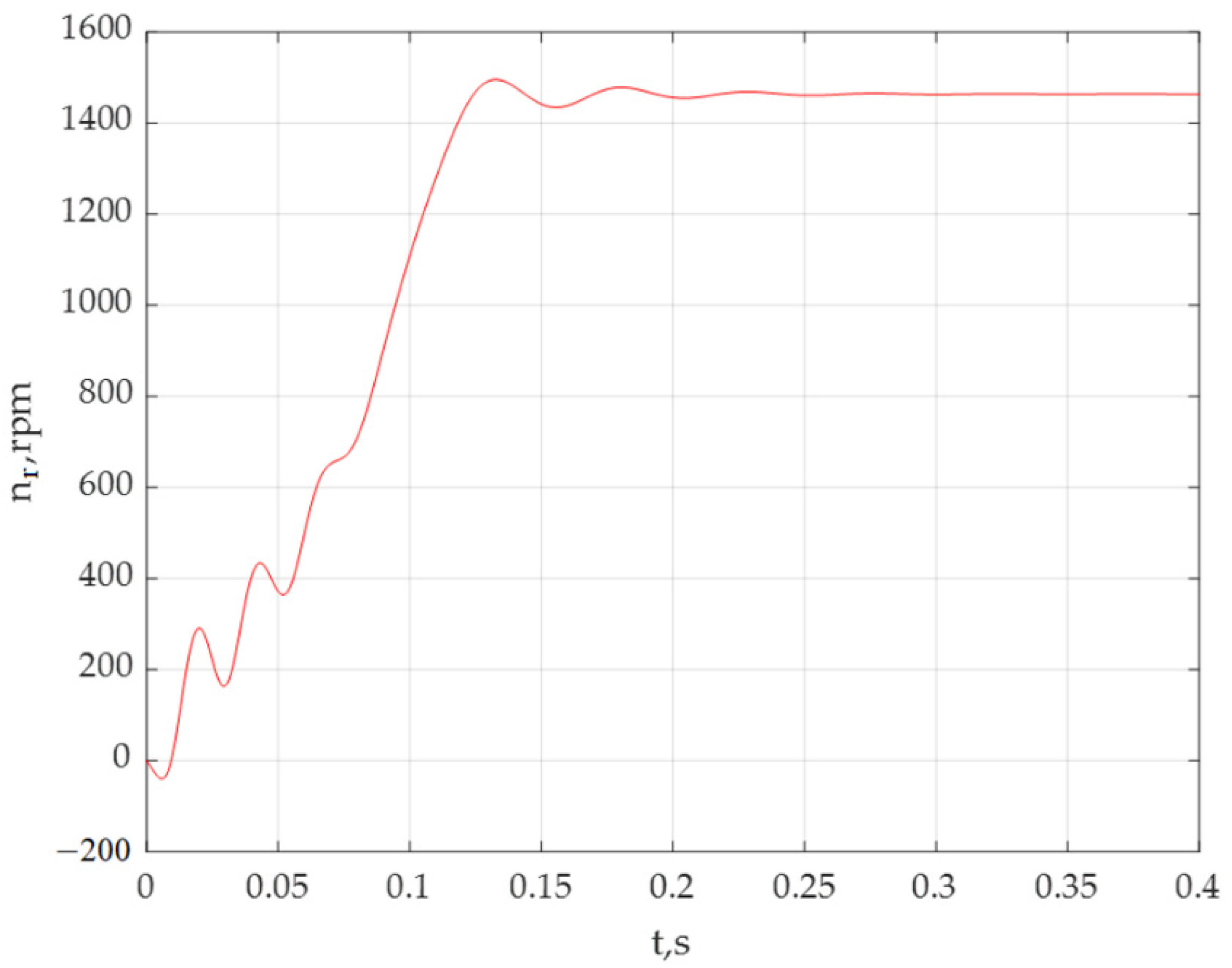
| Rated speed nr, rpm | 1450 |
| Number of phases n, items | 3 |
| Number of pole pairs pp, items | 2 |
| Power factor cosφ, r. u. | 0.847 |
| Efficiency η,% | 88.1 |
| Stator winding phase active resistance rs, Ω | 0.5 |
| Active resistance of the rotor winding reduced to the stator winding r′r, Ω | 0.36 |
| Stator winding leakage inductance Lσs, Hn | 0.001783 |
| Rotor winding leakage inductance reduced to the stator winding, L′σr, Hn | 0.002986 |
| Total inductance of the magnetizing circuit Lμ, Hn | 0.07266 |
| Number of phase turns of the stator winding ws, things | 96 |
| Number of rotor bars Zr, things | 64 |
| Stator winding length ls, m | 0.163 |
| Air gap length lβ, m | 0.128 |
| Stator radius rs, m | 0.255 |
| Rotor radius rr, m | 0.253 |
| Parameter of the Park Vector | Number of Working Turns of the Stator wsA | ||||
|---|---|---|---|---|---|
| wsA1 = 96 | wsA2 = 91 | wsA3 = 86 | wsA4 = 81 | wsA5 = 76 | |
| Current value Isd0, at Isq = 0, A | 30.946 | 31.183 | 31.398 | 31.66 | 31.854 |
| Current value Isq0, at Isd = 0, A | 30.946 | 30.685 | 30.418 | 30.192 | 29.897 |
| Instantaneous value of the phase A stator current IsA, A | 30.942 | 31.191 | 31.398 | 31.66 | 31.9 |
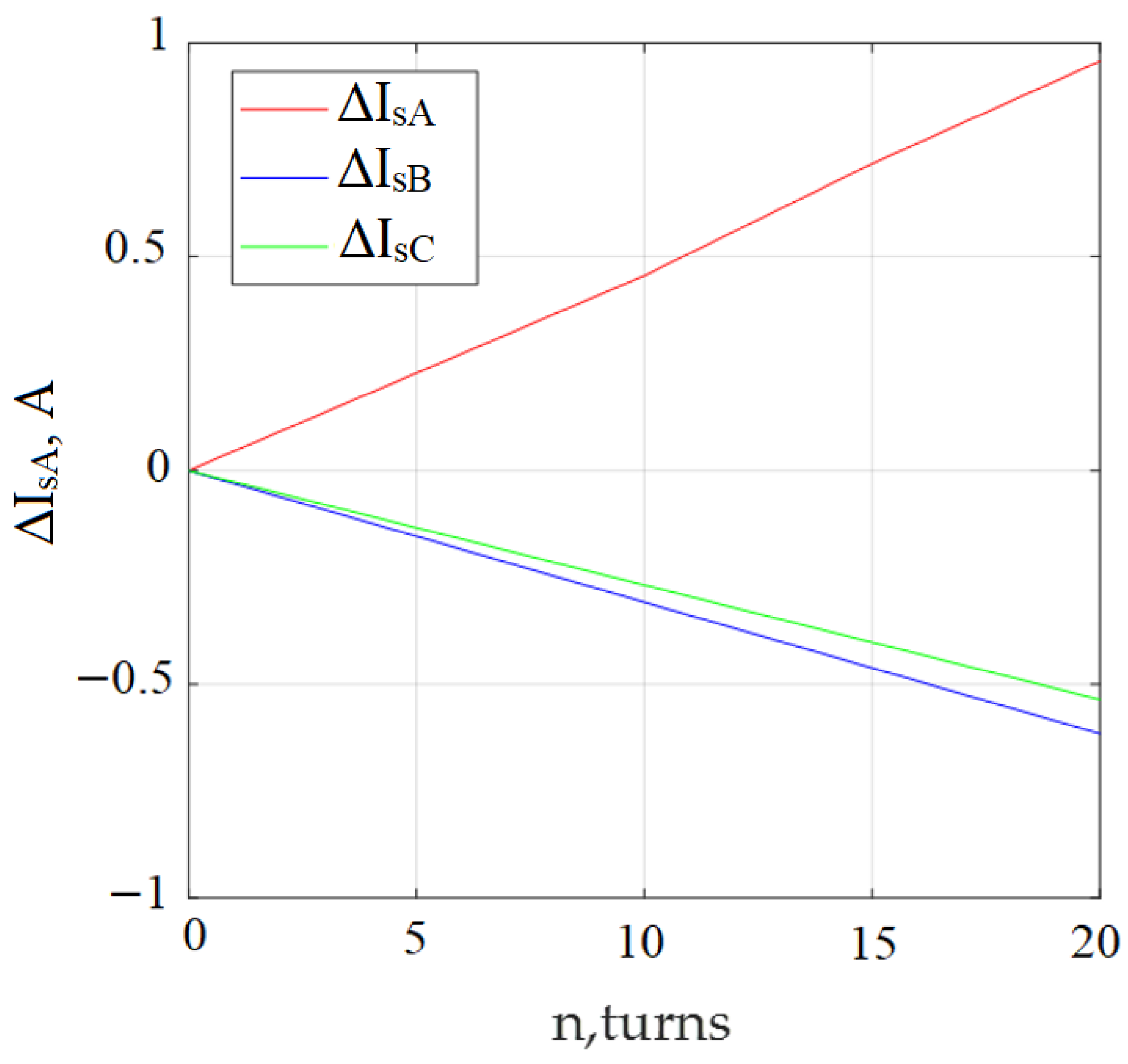
| Phase A stator current increment ΔIsA, A | 0 | 0.228 | 0.456 | 0.718 | 0.958 |
| Instantaneous value of the phase A stator current determined from the IsA diagram, A | 30.946 | 31.183 | 31.398 | 31.659 | 31.853 |
| Phase A stator current increment determined from the diagram ΔIsAm, A | 0 | 0.237 | 0.452 | 0.713 | 0.903 |
| Error in phase A stator current increment, δΔIsA, % | 0 | 3.95 | 0.88 | 0.69 | 5.74 |
| Instantaneous value of the phase B stator current IsB, A | 30.942 | 30.788 | 30.634 | 30.48 | 30.326 |
| Phase B stator current increment ΔIsB, A | 0 | −0.154 | −0.308 | −0.462 | −0.616 |
| Instantaneous value of the phase B stator current of determined from the IsB diagram, A | 30.946 | 30.791 | 30.627 | 30.507 | 30.318 |
| Phase B stator current increment determined from the diagram ΔIsBm, A | 0 | −0.155 | −0.319 | −0.439 | −0.628 |
| Error in determining the phase B stator current increment δΔIsB, % | 0 | 0.65 | 3.58 | 5.63 | 2.45 |
| Instantaneous value of the phase C stator current IsC, A | 30.942 | 30.808 | 30.674 | 30.54 | 30.406 |
| Phase C stator current increment ΔIsC | 0 | −0.134 | −0.268 | −0.402 | −0.536 |
| Instantaneous value of the phase C stator current, determined from the IsCm diagram, A | 30.946 | 30.81 | 30.667 | 30.567 | 30.401 |
| Phase C stator current increment determined from the diagram ΔIsCm, A | 0 | −0.136 | −0.279 | −0.379 | −0.545 |
| Error in determining the i of the phase C stator current increment, δΔIsC, % | 0 | 1.49 | 4.1 | 5.72 | 1.23 |
| The phase shift angle of the phase A stator current determined on the model, φIsAm, deg. | 31.32 | 30.921 | 30.522 | 30.123 | 29.724 |
| Displacement of the phase shift angle of phase A stator current ΔφIsA, deg. | 0 | −0.399 | −0.798 | −1.197 | −1.596 |
| The phase shift angle of phase A stator current determined on the model, φIsAm, deg. | 31.32 | 30.912 | 30.519 | 30.125 | 29.731 |
| The displacement of the phase shift angle of the phase A current determined on the model ΔφIsAm, deg. | 0 | −0.408 | −0.801 | −1.195 | −1.589 |
| The error in determining the displacement of the phase shift angle of the phase current A, δΔφIsA, % | 0 | 2.26 | 0.36 | 0.17 | 0.44 |
| The phase shift angle of phase B stator current φIsB, deg. | 31.32 | 31.342 | 31.364 | 31.386 | 31.408 |
| Stator phase B current phase shift ΔφIsB, deg. | 0 | 0.022 | 0.044 | 0.066 | 0.088 |
| The phase shift angle of the phase B stator current determined on the model, φIsBm, deg. | 31.32 | 31.341 | 31.363 | 31.384 | 31.406 |
| Displacement of the phase shift angle of phase B stator current determined on the model, ΔφIsBm, deg. | 0 | 0.021 | 0.043 | 0.064 | 0.086 |
| Error in determining the displacement of the phase shift angle of the phase current B, δΔφIsB, % | 0 | 4.45 | 2.27 | 3.03 | 2.27 |
| Phase shift angle of the phase C stator current φIsC, deg. | 31.32 | 31.342 | 31.364 | 31.386 | 31.408 |
| Phase shift angle of phase C current ΔφIsC, deg. | 0 | 0.022 | 0.044 | 0.066 | 0.088 |
| The phase angle of the phase C stator current determined on the model, φIsCm, deg. | 31.32 | 31.341 | 31.363 | 31.384 | 31.406 |
| Displacement of the phase shift angle of the phase C stator current determined on the model, ΔφIsCm, deg. | 0 | 0.021 | 0.043 | 0.064 | 0.086 |
| Error in determining the displacement of the phase shift angle of the current C, δΔφIsC, % | 0 | 4.45 | 2.27 | 3.03 | 2.27 |
| Ellipticity angle ε, deg. | 45.0 | 44.539 | 44.092 | 43.64 | 43.185 |
| Ellipse tilt angle θ, deg. | 0 | 0 | 0 | 0 | 0 |
| Parameter of the Park Vector | Stator Phase Voltage UsA, V | ||||
|---|---|---|---|---|---|
| UsA1 = 311 | UsA2 = 308 | UsA3 = 305 | UsA4 = 302 | UsA5 = 299 | |
| Current value Isd0, at Isq = 0, A | 31.398 | 30.85 | 29.985 | 29.3453 | 28.6192 |
| Current value Isq0, at Isd = 0, A | 30.418 | 31.2674 | 32.0223 | 32.7419 | 33.4207 |
| Current value Isd, at Ip = Ipmax, A | 31.398 | 15.6837 | 12.4823 | 12.088 | 12.0614 |
| Current value Isq, at Ip = Ipmax, A | 30.418 | −27.3015 | −31.9624 | −31.1955 | −32.2805 |
| The maximum value of the Park vector Ipmax, A | 31.398 | 31.4875 | 32.4585 | 33.4552 | 34.4603 |
| The minimum value of the Park vector Ipmin, A | 30.418 | 30.5226 | 29.6975 | 28.7509 | 28.0216 |
| Instantaneous value of the phase A stator current IsA, A | 31.398 | 30.875 | 30.039 | 29.37 | 28.694 |
| Phase A stator current increment ΔIsA, A | 0 | −0.523 | −1.359 | −2.028 | −2.704 |
| Instantaneous value of the phase A stator current determined from the IsA diagram, A | 31.398 | 30.85 | 29.987 | 29.354 | 28.645 |
| Phase A stator current increment determined from the diagram ΔIsAm, A | 0 | −0.548 | −1.411 | −2.044 | −2.753 |
| Error in determining the phase A stator current increment, δΔIsA, % | 0 | 5.25 | 3.83 | 0.79 | 1.81 |
| Instantaneous value of the phase B stator current IsB, A | 30.634 | 31.169 | 31.653 | 32.138 | 32.551 |
| Phase B stator current increment ΔIsB, A | 0 | 0.535 | 1.019 | 1.504 | 1.917 |
| Instantaneous value of the phase B stator current determined from the IsB diagram, A | 30.627 | 31.18 | 31.601 | 32.048 | 32.453 |
| Phase B stator current increment determined from the diagram ΔIsBm, A | 0 | 0.533 | 0.974 | 1.421 | 1.826 |
| Error in determining the phase B stator current increment, δΔIsB, % | 0 | 0.38 | 4.42 | 5.52 | 4.75 |
| Instantaneous value of the phase C stator current increment IsC, A | 30.674 | 31.169 | 31.505 | 31.906 | 32.263 |
| Phase C stator current increment ΔIsC, A | 0 | 0.495 | 0.831 | 1.232 | 1.589 |
| Instantaneous value of the phase C stator current determined from the IsC diagram, A | 30.667 | 31.164 | 31.528 | 31.933 | 32.301 |
| Phase C stator current increment determined from the diagram ΔIsCm, A | 0 | 0.497 | 0.861 | 1.266 | 1.634 |
| Error in determining the phase C stator current increment, δΔIsC, % | 0 | 0.4 | 3.61 | 2.78 | 2.83 |
| The phase shift angle of the phase A stator current φA, deg. | 30.522 | 31.634 | 32.973 | 34.122 | 35.342 |
| The displacement of the phase shift angle of phase A stator current ΔφIsA, deg. | 0 | 1.112 | 2.451 | 3.6 | 4.82 |
| The phase shift angle of the phase A stator current determined on the model, φIsAm, deg. | 30.519 | 31.663 | 33.017 | 34.173 | 35.397 |
| The displacement of phase shift angle of the phase A stator current determined on the model ΔφIsA, deg. | 0 | 1.144 | 2.498 | 3.654 | 4.878 |
| Error in determining the displacement of the phase shift angle of the phase current A, δΔIsA, % | 0 | 2.88 | 1.92 | 1.5 | 1.2 |
| The phase shift angle of phase B stator current φIsB, deg. | 31.364 | 31.304 | 31.244 | 31.184 | 31.124 |
| Stator phase B current phase shift ΔφIsB, deg. | 0 | −0.06 | −0.12 | −0.18 | −0.24 |
| The phase shift angle of the phase B stator current determined on the model, φIsBm, deg. | 31.363 | 31.302 | 31.236 | 31.183 | 31.13 |
| The displacement of the phase shift angle of the phase B stator current determined on the model, ΔφIsBm, deg. | 0 | −0.061 | −0.127 | −0.18 | −0.233 |
| Error in determining the displacement of the phase shift angle of the phase current B, δΔφIsB, % | 0 | 1.67 | 5.83 | 0 | 2.92 |
| The phase shift angle of the phase C stator current φIsC, deg. | 31.364 | 31.304 | 31.244 | 31.184 | 31.124 |
| Stator phase C current phase shift ΔφIsC, deg. | 0 | −0.06 | −0.12 | −0.18 | −0.24 |
| The phase angle of the phase C Stator phase B current phase shift determined on the model, φIsCm, deg. | 31.363 | 31.302 | 31.236 | 31.183 | 31.13 |
| The displacement of phase shift angle of the phase C stator current determined on the model, ΔφIsCm, deg. | 0 | −0.061 | −0.127 | −0.18 | −0.233 |
| Error in determining the displacement of the phase shift angle of the phase current C, δΔφIsC, % | 0 | 1.67 | 5.83 | 0 | 2.92 |
| Ellipticity angle in orthogonal–circular basis ε, deg. | 44.092 | 44.109 | 42.457 | 40.675 | 39.116 |
| Ellipticity angle in orthogonal–elliptic basis γ, deg. | 44.092 | 45.479 | 46.822 | 48.131 | 49.426 |
| Ellipse tilt angle θ, deg. | 0 | −60.124 | −68.668 | −68.819 | −69.512 |
| Parameter of the Park Vector | Number of Working Turns of the Stator wsA | ||||
|---|---|---|---|---|---|
| wsA1 = 96 | wsA2 = 91 | wsA3 = 86 | wsA4 = 81 | wsA5 = 76 | |
| Current value Isd0, at Isq = 0, A | 28.6982 | 29.8262 | 29.985 | 30.0266 | 30.5748 |
| Current value Isq0, at Isd = 0, A | 29.3945 | 32.2536 | 32.0223 | 31.79 | 31.5465 |
| Current value Isd, at Ip = Ipmax, A | 10.5215 | 11.4475 | 12.4823 | 14.706 | 16.2856 |
| Current value Isq, at Ip = Ipmax, A | −30.7401 | −30.6181 | −31.9624 | −29.0098 | −27.6087 |
| The maximum value of the Park vector Ipmax, A | 32.933 | 32.6881 | 32.4585 | 32.245 | 32.0541 |
| The minimum value of the Park vector Ipmin, A | 29.291 | 29.4919 | 29.6975 | 29.8965 | 30.0804 |
| Instantaneous value of the phase A stator current IsA, A | 28.76 | 30.01 | 30.039 | 30.04 | 30.57 |
| Phase A stator current increment ΔIsA, A | 0 | 1.09 | 1.341 | 1.28 | 1.81 |
| Instantaneous value of the phase A stator current determined from the IsA diagram, A | 28.698 | 29.829 | 29.987 | 30.028 | 30.575 |
| The increment of the phase A stator current determined from the diagram ΔIsAm, A | 0 | 1.131 | 1.289 | 1.33 | 1.877 |
| Error in determining the phase A stator current increment, δΔIsA, % | 0 | 3.76 | 3.88 | 3.91 | 3.7 |
| Instantaneous value of the phase B stator current IsB, A | 29.25 | 31.686 | 31.653 | 31.446 | 31.35 |
| Phase B stator current increment ΔIsB, A | 0 | 2.436 | 2.403 | 2.196 | 2.1 |
| Instantaneous value of the phase B stator current determined from the IsB diagram, A | 29.249 | 31.753 | 31.601 | 31.424 | 31.343 |
| Phase B stator current increment determined from the diagram ΔIsBm, A | 0 | 2.504 | 2.352 | 2.175 | 2.094 |
| Error in determining the phase B stator current increment, δΔIsB, % | 0 | 2.8 | 2.12 | 0.96 | 0.29 |
| Instantaneous value of the phase C stator current increment IsC, A | 29.06 | 31.582 | 31.505 | 31.229 | 31.06 |
| Phase C stator current increment ΔIsC, A | 0 | 2.522 | 2.445 | 2.169 | 2.0 |
| Instantaneous value of the phase C stator current determined from the IsC diagram, A | 29.222 | 31.668 | 31.528 | 31.36 | 31.307 |
| Phase C stator current increment determined from the diagram ΔIsCm, A | 0 | 2.446 | 2.306 | 2.138 | 2.085 |
| Error in determining the phase C stator current increment, δΔIsC, % | 0 | 3.01 | 5.69 | 1.43 | 4.25 |
| The phase shift angle of the phase A stator current φA, deg. | 31.91 | 33.28 | 32.973 | 32.741 | 32.094 |
| Offset of phase shift angle of stator phase A current ΔφIsA, deg. | 0 | 1.37 | 1.061 | 0.831 | 0.184 |
| The phase shift angle of the phase A stator current determined on the model, φIsAm, deg. | 31.933 | 33.345 | 33.017 | 32.791 | 32.122 |
| The displacement phase shift angle of the stator phase A current determined on the model ΔφIsA, deg. | 0 | 1.412 | 1.084 | 0.858 | 0.189 |
| The error in determining the displacement of the phase shift angle of the phase current A, δΔIsA, % | 0 | 3.07 | 2.17 | 3.25 | 2.72 |
| The phase shift angle of phase B stator current φIsB, deg. | 31.299 | 31.233 | 31.244 | 30.258 | 31.278 |
| Stator phase B current phase shift ΔφIsB, deg. | 0 | −0.066 | −0.055 | −0.041 | −0.021 |
| The phase shift angle of the phase B stator current determined on the model, φIsBm, deg. | 31.289 | 31.221 | 31.236 | 31.247 | 31.279 |
| Offset of phase shift angle of stator phase B current determined on the model, ΔφIsBm, deg. | 0 | −0.068 | −0.053 | −0.042 | −0.02 |
| Error in determining the displacement of the phase shift angle of the phase current B, δΔφIsB, % | 0 | 3.03 | 3.64 | 2.444 | 4.76 |
| The phase shift angle of the phase C stator current φIsC, deg. | 31.299 | 31.233 | 31.244 | 30.258 | 31.278 |
| Stator phase C current phase shift ΔφIsC, deg. | 0 | −0.066 | −0.055 | −0.041 | −0.021 |
| The phase angle of the phase C Stator phase B current phase shift determined on the model, φIsCm, deg. | 31.289 | 31.221 | 31.236 | 31.247 | 31.279 |
| Offset of phase shift angle of stator phase C current determined on the model, ΔφIsCm, deg. | 0 | −0.068 | −0.053 | −0.042 | −0.02 |
| Error in determining the displacement of the phase shift angle of the phase current C, δΔφIsC, % | 0 | 3.03 | 3.64 | 2.444 | 4.76 |
| Ellipticity angle in orthogonal–circular basis ε, deg. | 41.65 | 42.057 | 42.457 | 42.836 | 43.181 |
| Ellipticity angle in orthogonal–elliptic basis γ, deg. | 45.687 | 47.239 | 46.822 | 46.634 | 45.896 |
| Ellipse tilt angle θ, deg. | −71.105 | −69.5 | −68.668 | −63.118 | −59.465 |
| Parameter of the Park Vector | Stator Phase Voltage UsA, V | ||||
|---|---|---|---|---|---|
| UsA1 = 311 | UsA2 = 308 | UsA3 = 305 | UsA4 = 302 | UsA5 = 299 | |
| Isd0 current value determined for a symmetrical supply voltage system at Isq = 0, A | 31.398 | 31.398 | 31.398 | 31.398 | 31.398 |
| Current value Isq0, determined for a symmetrical system of supply voltages, at Isd = 0, A | 30.418 | 30.418 | 30.418 | 30.418 | 30.418 |
| Current value I′sd0, recalculated for the condition that the power supply system is symmetrical at Isq = 0, A | 31.398 | 31.395 | 31.4 | 31.398 | 31.397 |
| The current value I′sq0, recalculated for the condition that the power supply system is symmetrical at Isd = 0, A | 30.418 | 30.415 | 30.419 | 30.421 | 30.418 |
| Instantaneous value of the phase A stator current determined for a symmetrical system of supply voltages, IsA, A | 31.398 | 31.398 | 31.398 | 31.398 | 31.398 |
| The increment of the phase A stator current determined for a symmetrical system of supply voltages, ΔIsA, A | 0.452 | 0.452 | 0.452 | 0.452 | 0.452 |
| The instantaneous value of the phase A stator current recalculated for the condition that the power system is symmetrical IsA, A | 31.398 | 31.395 | 31.4 | 31.398 | 31.397 |
| Phase A stator current increment recalculated for the condition that the power supply system is symmetrical ΔIsAm, A | 0.452 | 0.449 | 0.454 | 0.452 | 0.451 |
| Error in determining the phase A stator current increment, γΔIsA, % | 0 | 0.66 | 0.44 | 0 | 0.66 |
| Instantaneous value of the phase B stator current, determined for a symmetrical system of supply voltages IsB, A | 30.634 | 30.634 | 30.634 | 30.634 | 30.634 |
| Phase B stator current increment determined for symmetrical supply voltage system ΔIsB, A | −0.308 | −0.308 | −0.308 | −0.308 | −0.308 |
| Instantaneous value of the phase B stator current increment, recalculated for the condition that the power system is symmetrical IsB, A | 30.634 | 30.624 | 30.628 | 30.629 | 30.627 |
| Phase B stator current increment determined from the diagram ΔIsBm, A | −0.308 | −0.322 | −0.318 | −0.317 | −0.319 |
| The error in determining the phase B stator current increment, in terms of the condition that the power supply system is symmetrical γΔIsB, % | 0 | 4.54 | 3.25 | 2.84 | 3.57 |
| Instantaneous value of the phase C stator current determined for a symmetrical system of supply voltages IsC, A | 30.667 | 30.667 | 30.667 | 30.667 | 30.667 |
| Phase C stator current increment determined for a symmetrical system of supply voltages ΔIsC, A | −0.279 | −0.279 | −0.279 | −0.279 | −0.279 |
| Instantaneous value of the phase C stator current recalculated for the condition that the power system is symmetrical IsC, A | 30.667 | 30.664 | 30.668 | 30.669 | 30.666 |
| Phase C stator current increment determined from the diagram ΔIsCm, A | −0.279 | −0.282 | −0.278 | −0.277 | −0.28 |
| Error in determining the phase C stator current increment, γΔIsC, % | 0 | 1.08 | 0.36 | 0.72 | 0.36 |
| The phase shift angle of the phase A stator current determined for a symmetrical system of supply voltages φA, deg. | 30.522 | 30.522 | 30.522 | 30.522 | 30.522 |
| Displacement of the phase shift angle of phase A current determined for a symmetrical system of stator supply voltages ΔφIsA, deg. | −0.798 | −0.798 | −0.798 | −0.798 | −0.798 |
| The phase shift angle of the of phase A stator current, in terms of the condition that the power supply system is symmetrical, φAm, deg. | 30.522 | 30.519 | 30.518 | 30.522 | 30.52 |
| The displacement of the phase shift angle of the phase A stator current, in terms of the condition that the power supply system is symmetrical ΔφIsA, deg. | 0 | −0.801 | −0.802 | −0.798 | −0.8 |
| Error in determining the displacement of the phase shift angle of the phase current, γΔIsA, % | 0 | 0.38 | 0.501 | 0 | 0.25 |
| The phase shift angle of the phase B stator current determined for a symmetrical system of supply voltages φB, deg. | 31.364 | 31.364 | 31.364 | 31.364 | 31.364 |
| The displacement of the phase shift angle of the stator phase B determined for a symmetrical supply voltage system ΔφIsB, deg. | 0.044 | 0.044 | 0.044 | 0.044 | 0.044 |
| The phase shift angle of the phase B stator current, in terms of the condition that the power supply system is symmetrical, φBm, deg. | 31.364 | 31.363 | 31.363 | 31.362 | 31.362 |
| The displacement of the phase shift angle of the current of phase B of the stator, in terms of the condition that the power supply system is symmetrical, ΔφIsB, deg. | 0.044 | 0.043 | 0.044 | 0.044 | 0.044 |
| Error in determining the displacement of the phase shift angle of the phase current B, γΔIsB, % | 0 | 2.33 | 0 | 0 | 0 |
| The phase angle of phase C stator current determined for a symmetrical system of supply voltages φC, deg. | 31.364 | 31.364 | 31.364 | 31.364 | 31.364 |
| The displacement of the phase shift angle of the phase C stator current determined for a symmetrical system of supply voltages ΔφIsC, deg. | 0.044 | 0.044 | 0.044 | 0.044 | 0.044 |
| The phase shift angle of the phase C stator current, in terms of the condition that the power system is symmetrical, φCm, deg. | 31.364 | 31.363 | 31.363 | 31.362 | 31.362 |
| The displacement of the phase shift angle of the phase C stator current, in terms of the condition that the power supply system is symmetrical, ΔφIsC, deg. | 0.044 | 0.043 | 0.044 | 0.044 | 0.044 |
| Error in determining the displacement of the phase shift angle of the phase current C, γΔIsC, % | 0 | 2.33 | 0 | 0 | 0 |
| The ellipticity angle in the new orthogonal–circular basis ε, deg. | 44.092 | 44.092 | 44.091 | 44.095 | 44.093 |
| Parameter of the Park Vector | Number of Working Turns of the Stator wsA | ||||
|---|---|---|---|---|---|
| wsA1 = 96 | wsA2 = 91 | wsA3 = 86 | wsA4 = 81 | wsA5 = 76 | |
| Isd0 current value determined for a symmetrical supply voltage system at Isq = 0, A | 30.946 | 31.183 | 31.398 | 31.66 | 31.854 |
| Current value Isq0, determined for a symmetrical system of supply voltages, at Isd = 0, A | 30.946 | 30.685 | 30.418 | 30.192 | 29.897 |
| Current value I′sd0, recalculated for the condition that the power supply system is symmetrical at Isq = 0, A | 30.947 | 31.183 | 31.4 | 31.661 | 31.853 |
| The current value I′sq0, recalculated for the condition that the power supply system is symmetrical at Isd = 0, A | 30.945 | 30.681 | 30.419 | 30.196 | 29.893 |
| Instantaneous value of the phase A stator current determined for a symmetrical system of supply voltages, IsA, A | 30.942 | 31.191 | 31.398 | 31.66 | 31.9 |
| The increment of the phase A stator current determined for a symmetrical system of supply voltages, ΔIsA, A | 0 | 0.228 | 0.456 | 0.718 | 0.958 |
| The instantaneous value of the phase A stator current recalculated for the condition that the power system is symmetrical IsA, A | 30.947 | 31.183 | 31.4 | 31.66 | 31.852 |
| Phase A stator current increment recalculated for the condition that the power supply system is symmetrical ΔIsAm, A | 0 | 0.236 | 0.453 | 0.718 | 0.905 |
| Error in determining the phase A stator current increment, γΔIsA, % | 0 | 3.51 | 0.66 | 0 | 5.53 |
| Instantaneous value of the phase B stator current, determined for a symmetrical system of supply voltages IsB, A | 30.942 | 30.788 | 30.634 | 30.48 | 30.326 |
| Phase B stator current increment determined for symmetrical supply voltage system ΔIsB, A | 0 | −0.154 | −0.308 | −0.462 | −0.616 |
| Instantaneous value of the phase B stator current increment, recalculated for the condition that the power system is symmetrical IsB, A | 30.945 | 30.788 | 30.628 | 30.51 | 30.315 |
| Phase B stator current increment determined from the diagram ΔIsBm, A | 0 | −0.157 | −0.317 | −0.435 | −0.63 |
| The error in determining the phase B stator current increment, in terms of the condition that the power supply system is symmetrical γΔIsB, % | 0 | 1.95 | 2.92 | 5.84 | 2.27 |
| Instantaneous value of the phase C stator current determined for a symmetrical system of supply voltages IsC, A | 30.942 | 30.808 | 30.674 | 30.54 | 30.406 |
| Phase C stator current increment determined for a symmetrical system of supply voltages ΔIsC, A | 0 | −0.134 | −0.268 | −0.402 | −0.536 |
| Instantaneous value of the phase C stator current recalculated for the condition that the power system is symmetrical IsC, A | 30.946 | 30.807 | 30.668 | 30.57 | 30.397 |
| Phase C stator current increment determined from the diagram ΔIsCm, A | 0 | −0.139 | −0.278 | −0.376 | −0.549 |
| Error in determining the phase C stator current increment, γΔIsC, % | 0 | 3.73 | 3.73 | 6.47 | 2.43 |
| The phase shift angle of the phase A stator current determined for a symmetrical system of supply voltages φA, deg. | 31.32 | 30.921 | 30.522 | 30.123 | 29.724 |
| Displacement of the phase shift angle of phase A current determined for a symmetrical system of stator supply voltages ΔφIsA, deg. | 0 | −0.399 | −0.798 | −1.197 | −1.596 |
| The phase shift angle of the of phase A stator current, in terms of the condition that the power supply system is symmetrical, φAm, deg. | 31.318 | 30.909 | 30.518 | 30.128 | 29.728 |
| The displacement of the phase shift angle of the phase A stator current, in terms of the condition that the power supply system is symmetrical ΔφIsA, deg. | 0 | −0.409 | −0.8 | −1.19 | −1.59 |
| Error in determining the displacement of the phase shift angle of the phase current, γΔIsA, % | 0 | 2.51 | 0.25 | 0.36 | 0.38 |
| The phase shift angle of the phase B stator current determined for a symmetrical system of supply voltages φB, deg. | 31.32 | 31.342 | 31.364 | 31.386 | 31.408 |
| The displacement of the phase shift angle of the stator phase B determined for a symmetrical supply voltage system ΔφIsB, deg. | 0 | 0.022 | 0.044 | 0.066 | 0.088 |
| The phase shift angle of the phase B stator current, in terms of the condition that the power supply system is symmetrical, φBm, deg. | 31.32 | 31.342 | 31.363 | 31.384 | 31.407 |
| The displacement of the phase shift angle of the current of phase B of the stator, in terms of the condition that the power supply system is symmetrical, ΔφIsB, deg. | 0 | 0.022 | 0.043 | 0.064 | 0.087 |
| Error in determining the displacement of the phase shift angle of the phase current B, γΔIsB, % | 0 | 0 | 2.27 | 3.03 | 1.14 |
| The phase angle of phase C stator current determined for a symmetrical system of supply voltages φC, deg. | 31.32 | 31.342 | 31.364 | 31.386 | 31.408 |
| The displacement of the phase shift angle of the phase C stator current determined for a symmetrical system of supply voltages ΔφIsC, deg. | 0 | 0.022 | 0.044 | 0.066 | 0.088 |
| The phase shift angle of the phase C stator current, in terms of the condition that the power system is symmetrical, φCm, deg. | 31.32 | 31.342 | 31.363 | 31.384 | 31.407 |
| The displacement of the phase shift angle of the phase C stator current, in terms of the condition that the power supply system is symmetrical, ΔφIsC, deg. | 0 | 0.022 | 0.043 | 0.064 | 0.087 |
| Error in determining the displacement of the phase shift angle of the phase current C, γΔIsC, % | 0 | 0 | 2.27 | 3.03 | 1.14 |
| The ellipticity angle in the new orthogonal–circular basis ε, deg. | 44.998 | 44.535 | 44.091 | 43.643 | 43.182 |
Publisher’s Note: MDPI stays neutral with regard to jurisdictional claims in published maps and institutional affiliations. |
© 2022 by the authors. Licensee MDPI, Basel, Switzerland. This article is an open access article distributed under the terms and conditions of the Creative Commons Attribution (CC BY) license (https://creativecommons.org/licenses/by/4.0/).
Share and Cite
Gerlici, J.; Goolak, S.; Gubarevych, O.; Kravchenko, K.; Kamchatna-Stepanova, K.; Toropov, A. Method for Determining the Degree of Damage to the Stator Windings of an Induction Electric Motor with an Asymmetric Power System. Symmetry 2022, 14, 1305. https://doi.org/10.3390/sym14071305
Gerlici J, Goolak S, Gubarevych O, Kravchenko K, Kamchatna-Stepanova K, Toropov A. Method for Determining the Degree of Damage to the Stator Windings of an Induction Electric Motor with an Asymmetric Power System. Symmetry. 2022; 14(7):1305. https://doi.org/10.3390/sym14071305
Chicago/Turabian StyleGerlici, Juraj, Sergey Goolak, Oleg Gubarevych, Kateryna Kravchenko, Kateryna Kamchatna-Stepanova, and Andrey Toropov. 2022. "Method for Determining the Degree of Damage to the Stator Windings of an Induction Electric Motor with an Asymmetric Power System" Symmetry 14, no. 7: 1305. https://doi.org/10.3390/sym14071305
APA StyleGerlici, J., Goolak, S., Gubarevych, O., Kravchenko, K., Kamchatna-Stepanova, K., & Toropov, A. (2022). Method for Determining the Degree of Damage to the Stator Windings of an Induction Electric Motor with an Asymmetric Power System. Symmetry, 14(7), 1305. https://doi.org/10.3390/sym14071305