Article

Self-Frequency Shift in Transmission of Asymmetric Pulse in Optical Medium

1
Hangzhou Institute of Advanced Studies, Zhejiang Normal University, Hangzhou 311231, China
2
Ceyear Technologies Co., Ltd., Qingdao 266555, China
3
State Key Laboratory of Modern Optical Instrumentation, College of Optical Science and Engineering, Zhejiang University, Hangzhou 310027, China
*
Author to whom correspondence should be addressed.
Symmetry 2022, 14(4), 834; https://doi.org/10.3390/sym14040834
Submission received: 28 February 2022 / Revised: 6 April 2022 / Accepted: 14 April 2022 / Published: 18 April 2022
(This article belongs to the Section Physics)

Abstract

:
Linear and nonlinear effects often induce a pulse self-frequency shift as it propagates along with an optical medium. Here, we theoretically investigate the transmission dynamics of asymmetric pulses propagating along with an optical medium in the temporal and spectral domains. Due to the asymmetric nonlinear phase-shift effect in the optical medium, the peak wavelength of asymmetric pulses exhibits a redshift or a blueshift in the spectral domain, while it slows down or speeds up in the temporal domain. Our results show that the peak wavelength shift initiated by a temporal or spectral asymmetric pulse depends not only on the pulse intensity, but also on the initial pulse chirp and dispersion of optical medium. We find that the peak wavelength shift of the asymmetric pulse increases with the pulse intensity and the initial pulse chirp, together with the spectrum width. The temporal and frequency shifts of the asymmetric pulses are found to be sensitive to the asymmetry ratio as well. These excellent properties may lead to the realization of a self-frequency shift-based tunable light source by launching asymmetric pulses into an optical medium.

1. Introduction

Optical soliton, which arises from the balance between dispersion and nonlinearity, has been widely studied in various fields, including optical communication, micromachining, biomedical, and so on [1,2,3,4]. The output pulse trains, which are mostly generated from mode-locked fiber lasers [5,6], can be theoretically described by means of the generalized nonlinear Schrödinger equation (NLSE) or the Ginzburg–Landau equation (GLE) [7,8]. In several previous experiments on optical soliton propagation in optical fibers or optical waveguides, the self-steepening effect which results from the intensity dependence of the group velocity can lead to an asymmetry spectrum during the process of self-phase modulation (SPM)-induced spectrum broadening [9,10,11,12]. To accurately describe the evolution dynamics of optical soliton propagating along with an optical medium, linear and nonlinear effects, including group dispersion, nonlinearity, and high-order effects, often should be taken into account [13,14]. As a result, the pulse spectrum exhibits a redshift or a blueshift, which is also called a self-frequency shift. In general, the spectrum of optical soliton with symmetric temporal profiles and spectrum almost remains unchanged during propagation in optical fibers. However, the self-frequency shift plays a significant role for several practical applications, including supercontinuum generation [15], tunable femtosecond pulse sources [16], and so on. There are several ways to generate the self-frequency shift. For instance, when optical soliton propagates along with optical fibers, a spectrum redshift, which is also called the Raman-induced frequency shift (RIFS), often occurs due to optical phonons Raman scattering [17,18,19]. The cross-phase modulation-induced modulation instability can lead to the breakup of intense continuous wave radiation into a train of ultrashort pulses with a self-frequency shift [20]. More recently, Chang et al. proposed the method of SPM-enabled spectral selection, which can achieve an octave-spanning wavelength-shift [21,22]. Besides those, nonlinear metamaterials [23], topographic optical fiber [24], and other photonic crystal fibers [25,26,27] have been widely used to generate the self-frequency shift. Among those works, self-frequency shifts with an asymmetric spectrum have been studied.
Although linear and nonlinear effects have been widely investigated in nonlinear medium, most of the mentioned research focuses on an input optical pulse with symmetric temporal profiles and spectrum, for instance, sech-shaped, Gaussian, or super-Gaussian. However, during the propagation, a nonlinear pulse with asymmetric temporal profiles or spectrum can often be obtained due to the high-order effects. For instance, when the third-order dispersion effect of the optical medium is more prominent, the symmetric pulse turns into an asymmetric pulse [13]. As the nonlinear pulse still undergoes the balance between the dispersion and nonlinearity, we can denote the asymmetric pulse as asymmetric soliton in a broad sense. The asymmetric pulse can exhibit self-acceleration or self-deceleration depending on its tail behind or in front of its main lobe [28]. For the asymmetric pulse, the unbalance between group dispersion and the nonlinear effect may result in an overcompensated nonlinear phase shift. The influence of a nonlinear phase shift on the propagation of vector asymmetrical soliton has been studied in a nonlinear dissipative system in which XPM dominates the propagation dynamics, showing that the pulses’ spectra exhibit redshift and blueshift alternately with a unique trajectory of pulse trapping [29]. Moreover, asymmetrical surface soliton trains [30], spectral asymmetry of optical breathers in the Manakov system [31,32], and strongly asymmetric soliton explosions [33] have been widely studied in theory. However, third-order dispersion should often be considered in the equation. Although, similar works about asymmetric evolution have been studied [9,34,35]. Although nonlinear pulses have been widely observed in experiments, the evolution dynamics of asymmetric pulses as the input pulse in an optical medium in the temporal and spectral domains has rarely been thoroughly studied.
In this paper, we have numerically studied the evolution dynamics of asymmetric pulses in an optical medium in the temporal and spectral domains. The peak wavelength of the asymmetric pulse exhibits a redshift or a blueshift in the spectral domain, while it slows down or speeds up in the temporal domain due to the asymmetric nonlinear phase-shift effect in the optical medium. Our numerical results show that temporal and frequency shifts of the asymmetric pulse are related to the launched pulse intensity, initial pulse chirp, propagation distance, dispersion of optical medium, and the asymmetry ratio. The peak wavelength shift of the asymmetric pulse increases with the pulse intensity and initial pulse chirp, together with the spectrum width. It is found that the spectral-asymmetric pulse has more advantages in terms of the spectral continuous tuning range. Unlike symmetric pulses, these excellent simulated features of the asymmetric pulse may extend the understanding of soliton nonlinear dynamics and lead to the realization and control of a self-frequency shift-based spectral tunable light source by launching asymmetric pulses into an optical medium.

2. Simulation Model

To study the propagation dynamics of the asymmetric pulse in an optical medium, we assume that the initial input pulse has two different situations, which correspond to a temporal-asymmetric pulse (TAP) and spectral-asymmetric pulse (SAP), respectively. The temporal profiles and optical spectra are depicted as shown in Figure 1. For case one, the time-varying envelope of the electric field of initial TAP can be written as [13]:
E 1 ( t , Z = 0 ) = a P 1 A 1 ( t + Δ τ 0 ) exp ( i C 1 t 2 )
where a is an intensity-dependent parameter, which means the multiple times of pulse intensity, and is introduced to increase the maximum amplitude of the initially launched pulse intensity, P1 is the peak power of the initial pulse, which is determined in Figure 1a, A1 is the slowly varying amplitude of the incidence pulse envelope, and Δτ0 and C1 are the initial time offset and chirp. The pulse envelope is superimposed by two closely Gaussian pulses, resulting as an asymmetric pulse in the temporal domain. The separation between the two pulses is set to be 0.6 ps and the pulse width is 0.3 ps. The detailed pulse envelope formed by superposition can be seen in Figure 1a, indicating that the temporal profile of TAP is asymmetric, with C1 = 0. Meanwhile, the corresponding spectrum depicted in Figure 1b shows Gaussian-like symmetry by Fourier transform of the temporal profile in Figure 1a.
For case two (i.e., SAP), the pulse should be maintained as symmetric in the temporal domain. To obtain the initial asymmetric spectrum, the initial chirp of this pulse should be assumed as a third-order nonlinear type, as shown by the blue line in Figure 1c. As our assumed nonlinear chirp here is positive parabolic-like, as depicted by the blue line in Figure 1c, the peak wavelength exhibits a redshift. On the contrary, if the nonlinear chirp here is negative parabolic-like, it manifests a blueshift. To simplify the description of influence factors, the time-varying envelope of the electric field of initial SAP can be written as:
E 2 ( t , Z = 0 ) = a P 2 A 2 ( t ) exp ( i C 2 t 2 )
where P2 and C2 are the peak power and chirp of the initial spectral-asymmetric pulse, and A2 is the slowly varying amplitude of the incidence pulse envelope, as shown in Figure 1c, in which the pulse width is set to be 0.3 ps. For the convenience of representing spectral asymmetry, the electric field in the frequency domain can be described as E 2 ( ω , Z = 0 ) = U 2 ( ω + Δ ω 0 ) . Here, Δ ω 0 = 2 π c Δ λ 0 / λ 2 is the frequency offset, where c is the light speed in the vacuum, Δλ0 is the initial peak wavelength offset, and λ is the center wavelength. The corresponding spectrum can be seen in Figure 1d. It is easy to find that there is somehow offset of the peak wavelength.
The propagation dynamics of these pulses in optical medium can be modeled by the nonlinear Schrödinger equation (NLSE) without gain and high-order effects (such as Raman scattering), as follows:
u z = i β 2 2 2 u t 2 + i γ | u | 2 u
where u(z, t) is the amplitude envelope of the pulse field, β2 is the dispersion of the optical medium, and γ is the cubic refractive nonlinearity of the optical medium. Here, the gain and loss are not considered due to the transmission dynamics in the optical medium. The standard split-step Fourier method was employed to numerically solve Equation (3) for the propagation dynamics of the asymmetric pulse in an optical medium without emphasis on the role of the high-order effect [13]. We assume the parameters of the optical medium as β2 = 20 ps2/km and γ = 4.5 W−1km−1 in our simulations to possibly match the experimental conditions of a single-mode fiber. What needs to be emphasized is that the parameters here are not immutable. They might be changed according to the experiment conditions.

3. Numerical Results

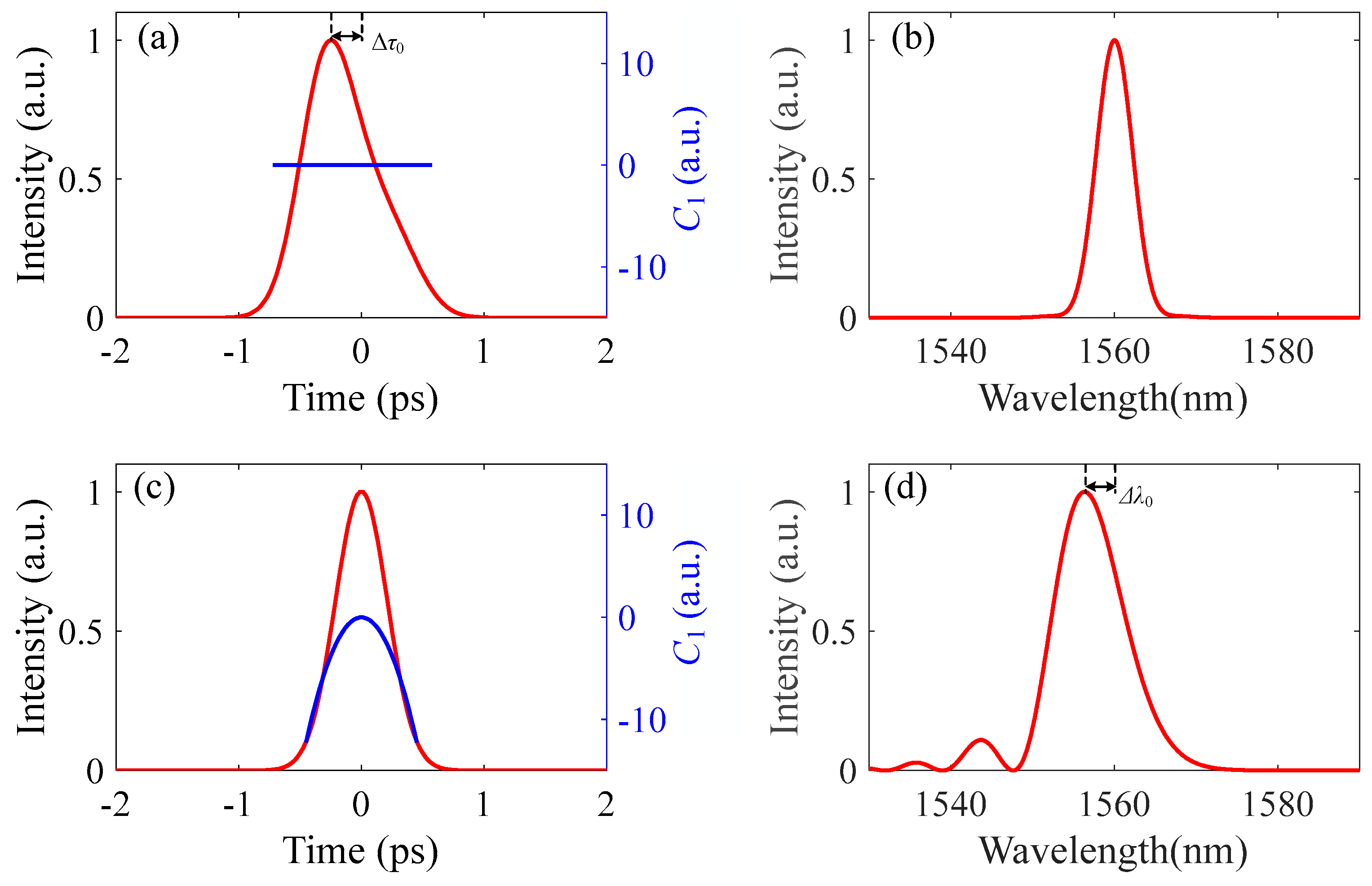
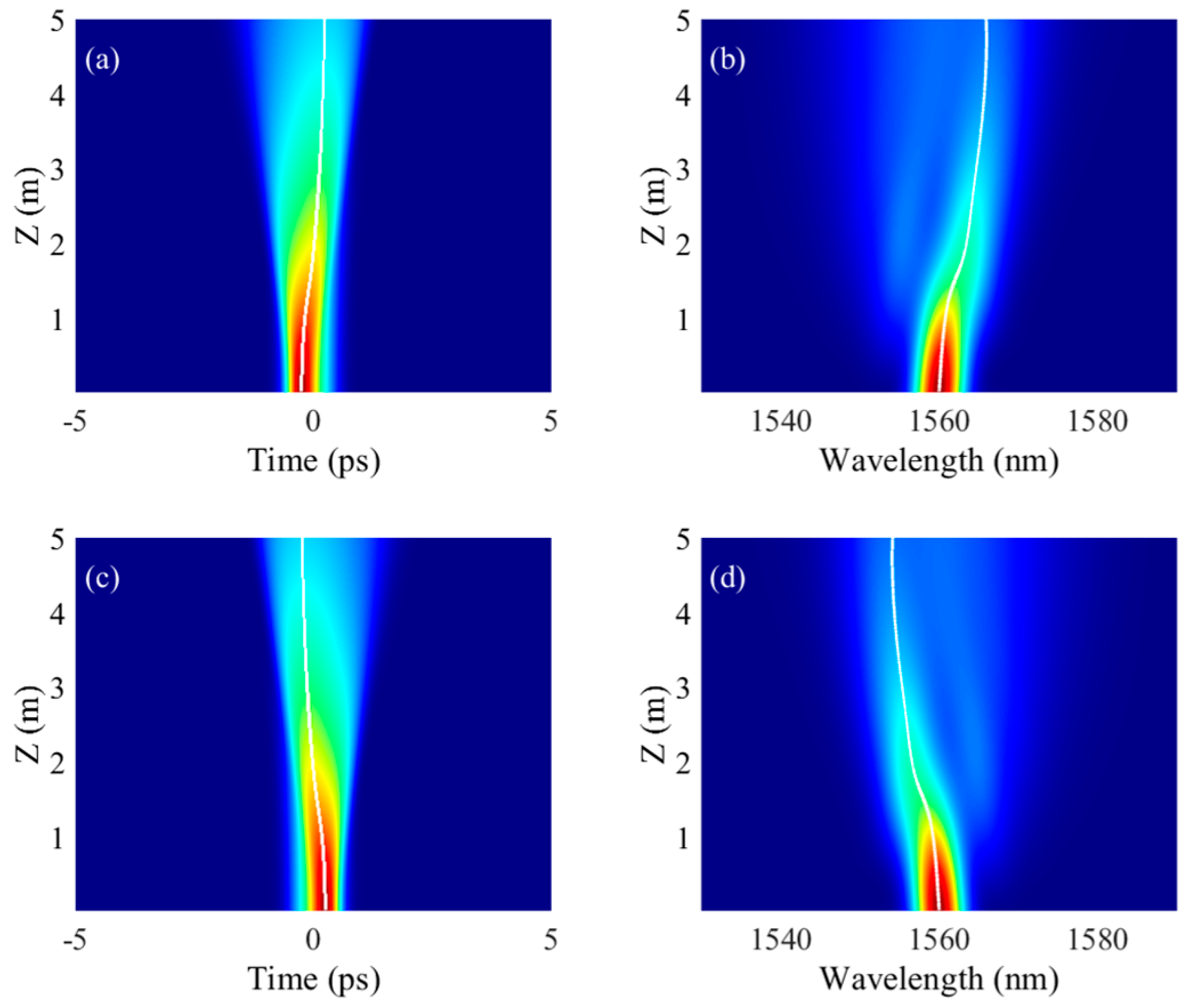
3.1. Propagation Dynamics of Temporal-Asymmetric Pulse

Figure 2 shows the temporal and spectral evolution dynamics of the TAP in the normal dispersion regime with the intensity-dependent parameter a = 2. In Figure 2a,b, the temporal profile and spectrum of the initial input pulse are the same as that in Figure 1a,b. As the initial time offset is negative, we denote it as the temporal left-asymmetric pulse (TLAP). On the contrary, we denote it as the temporal right-asymmetric pulse (TRAP) when the initial time offset is positive. As shown in Figure 2, the temporal and spectral evolution dynamics are apparently different from those of a traditional symmetric pulse. For simplification, the propagation distance, Z, here is set as 5 m. In general, optical soliton with a sech2-shaped or Gaussian profile remains highly symmetric when propagating along with normal or negative dispersion of the optical medium without considering the high-order effects. Figure 2a shows that, when the temporal-asymmetric pulse propagates along with the optical medium, the pulse width gradually increases. Meanwhile, it displays a bending trajectory in the time domain, as depicted by the white line in Figure 2a. The trajectory is directly related to the propagating speed of the pulse. As the bending trajectory tends to the positive time direction, the group velocity of LAP gradually slows down.
In the frequency domain as shown in Figure 2b, a similar bending trajectory of the spectrum can be seen as well, indicating that the spectrum displays a redshift. The final frequency shift here is about 5.86 nm. Moreover, the temporal deceleration rate and spectral redshift rate are directly proportional to the intensity-dependent parameter a. The larger the value of intensity-dependent a, the more evident the time delay and wavelength redshift become, if assuming a fixed propagation distance. The reason for this behavior can be understood as follows. Spectral variation depends on the fact that a positive chirped pulse undergoes spectral broadening through self-phase modulation (SPM) [29]. Under the action of SPM, the TAP can introduce the asymmetric nonlinear phase shift. It appears as the enhancement of the spectral asymmetry that the peak wavelength departs from the center wavelength with spectral broadening. It was found that the process is dependent on the pulse intensity determining the nonlinear effect [29]. Therefore, the spectrum shifts significantly towards a longer wavelength due to the contribution of the nonlinear phase shift. For the TRAP, the evolution dynamics are opposite to those of TLAP. The asymmetric pulse speeds up in the temporal domain and exhibits a spectral blueshift in the frequency domain, as shown in Figure 2c,d. As a result, we can conclude that the asymmetric shape of the pulse plays a major role for the frequency shift direction, which is largely different from that of a Raman-induced frequency shift. More importantly, the redshift and blueshift can both be achieved, which provides a flexible tool to adjust the laser wavelength.

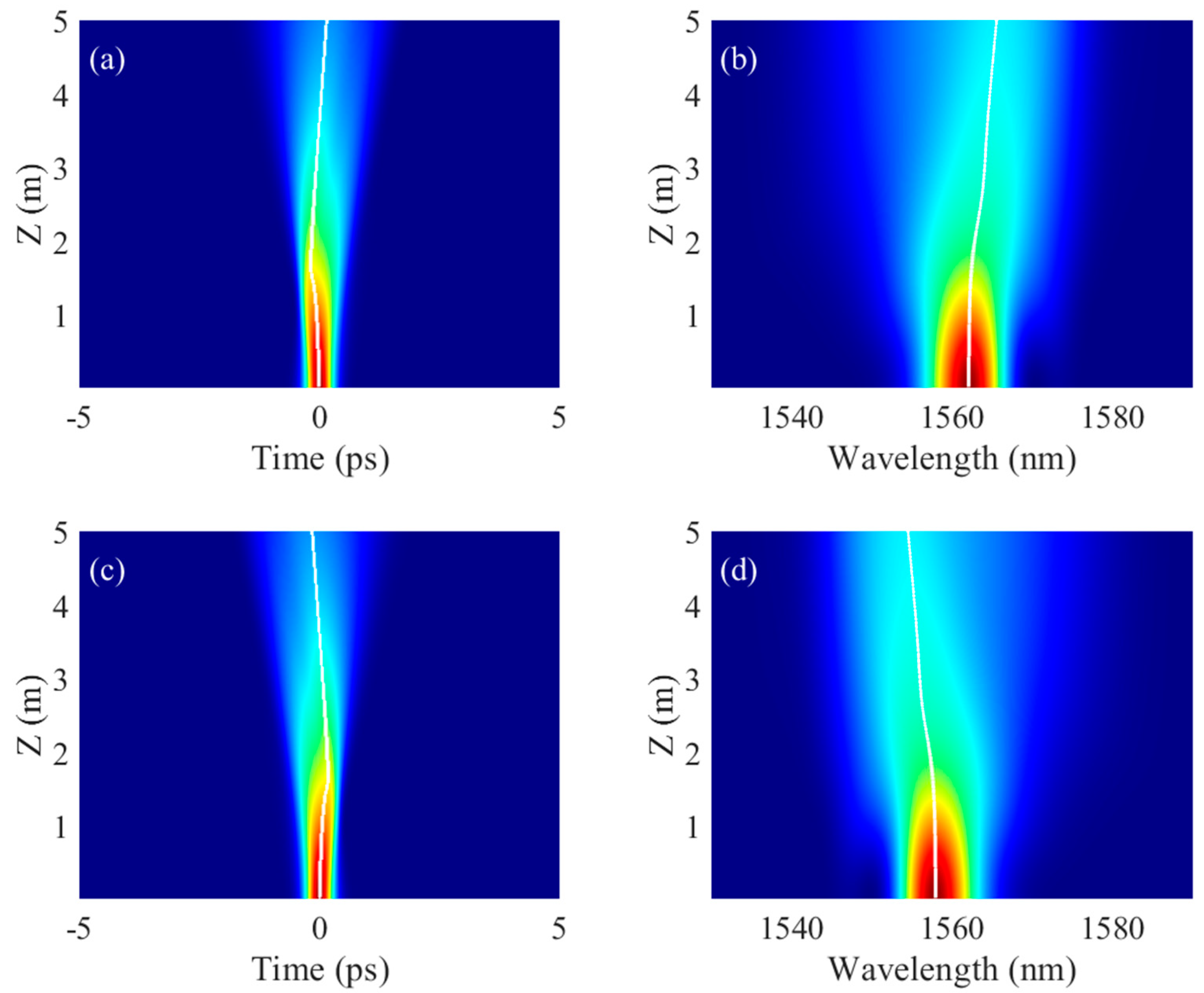
3.2. Propagation Dynamics of Spectral-Asymmetric Pulse

For another case, the symmetric pulse with nonlinear chirp results in a spectral-asymmetric pulse in the frequency domain, as shown in Figure 1d. Figure 3 shows the temporal and spectral evolution dynamics of the SAP with a fixed intensity-dependent parameter (a = 2). When the assumed nonlinear chirp is positive parabolic-like, we describe it as the spectral right-asymmetric pulse (SRAP). On the contrary, we denote it as the spectral left-asymmetric pulse (SLAP) with the negative parabolic-like nonlinear chirp. As shown in Figure 3a, the propagation speed of SRAP becomes faster first and then slows down gradually at the distance of Z = 1.64 m in the time domain. Meanwhile, the spectrum exhibits a redshift in the frequency domain, as shown in Figure 3b. The pulse width and spectrum bandwidth increase as well. This can be obviously manifested as the bending trajectory in the temporal domain and the spectral blueshift in the frequency domain. The bending trajectory can be attributed to the initial chirp. For SRAP, the initial chirp is positive parabolic-like. Therefore, it will be compensated by a linear and generated nonlinear phase shift. When the symmetric parabolic-like nonlinear chirp is decreasing, the asymmetric nonlinear phase shift plays a major role during the propagation in the medium. Similarly, the temporal acceleration rate and spectral blueshift rate are directly proportional to the intensity-dependent parameter a. The larger the value of intensity-dependent a, the more evident the time delay and peak wavelength blueshift become, if assuming a fixed propagation distance. It is easy to find that the SLAP shows the opposite propagation dynamics both in the temporal and the frequency domain, which are similar to those of TAP.
Compared with the propagation dynamics of these two types of asymmetric pulses, we can find that the temporal shifts are all not very prominent, while the peak wavelength shifts are obvious. Here, temporal shifts are all within 1 ps, while the maximum frequency shifts for SRAS and SLAS are 3.46 and −3.43 nm, respectively. It should be noted that the initial frequency shift of the spectral-asymmetric pulse is about −3.6 nm. The frequency shifts of TAP are much larger than those of SAP for a fixed intensity-dependent parameter. With further increment of the propagation distance, they are quite sensitive to the intensity-dependent parameter, with its value in the range from 1 to 2.5, which is discussed in the following section. This is very useful for spectral tuning based on the self-induced frequency shift of the asymmetric pulse.
It should be noted that the SPM-induced self-frequency shift is generally accompanied with the spectral broadening, which means that the frequency shift can only be realized for part of the original pulse. With the larger frequency shift, the spectral width is also larger, and less energy is transferred. Therefore, the intensity-dependent parameter is limited to 2.5 or below to avoid the too-low conversion efficiency. However, the self-frequency shift is still a meaningful method to control the pulse wavelength within tens of nanometers.

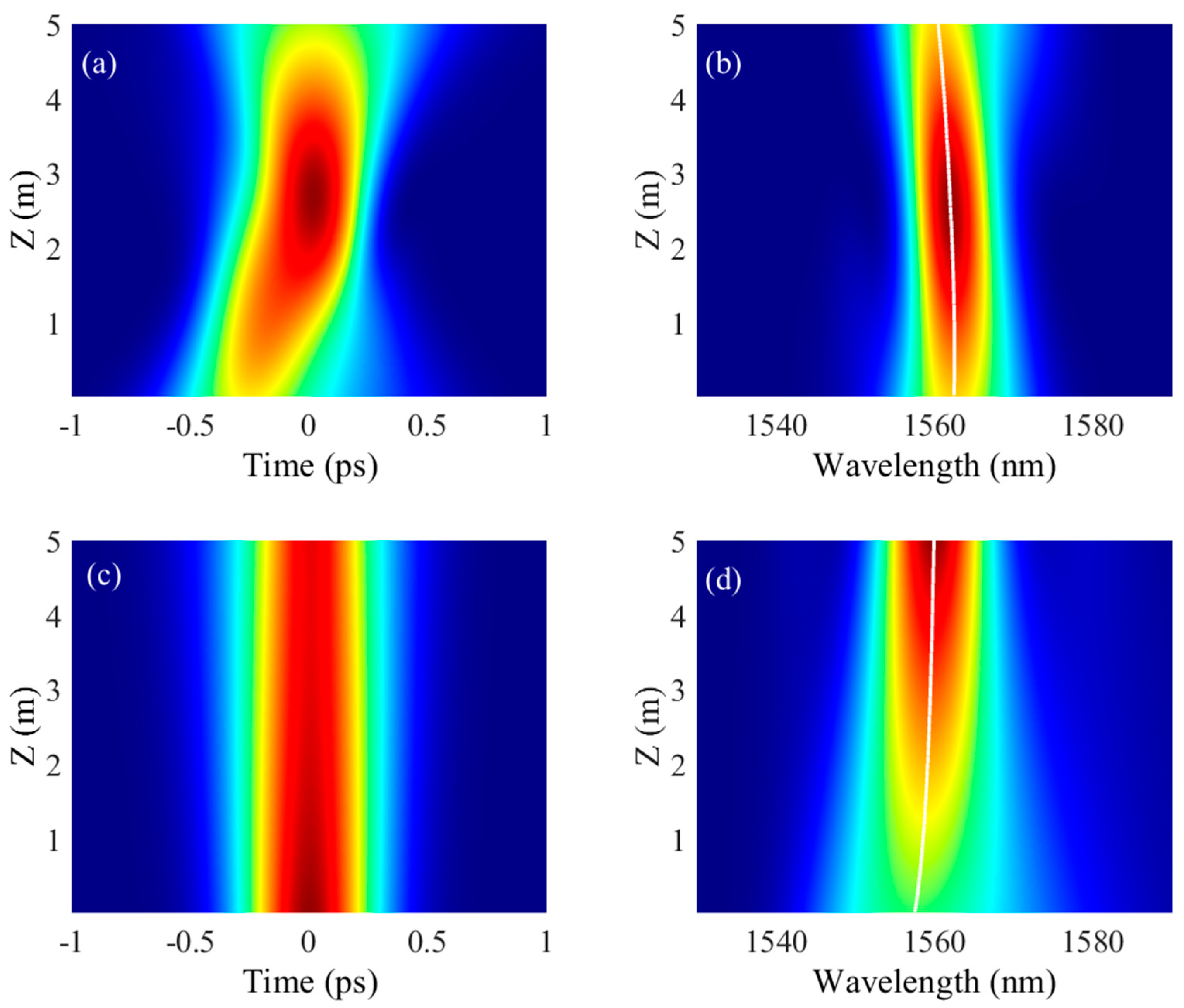
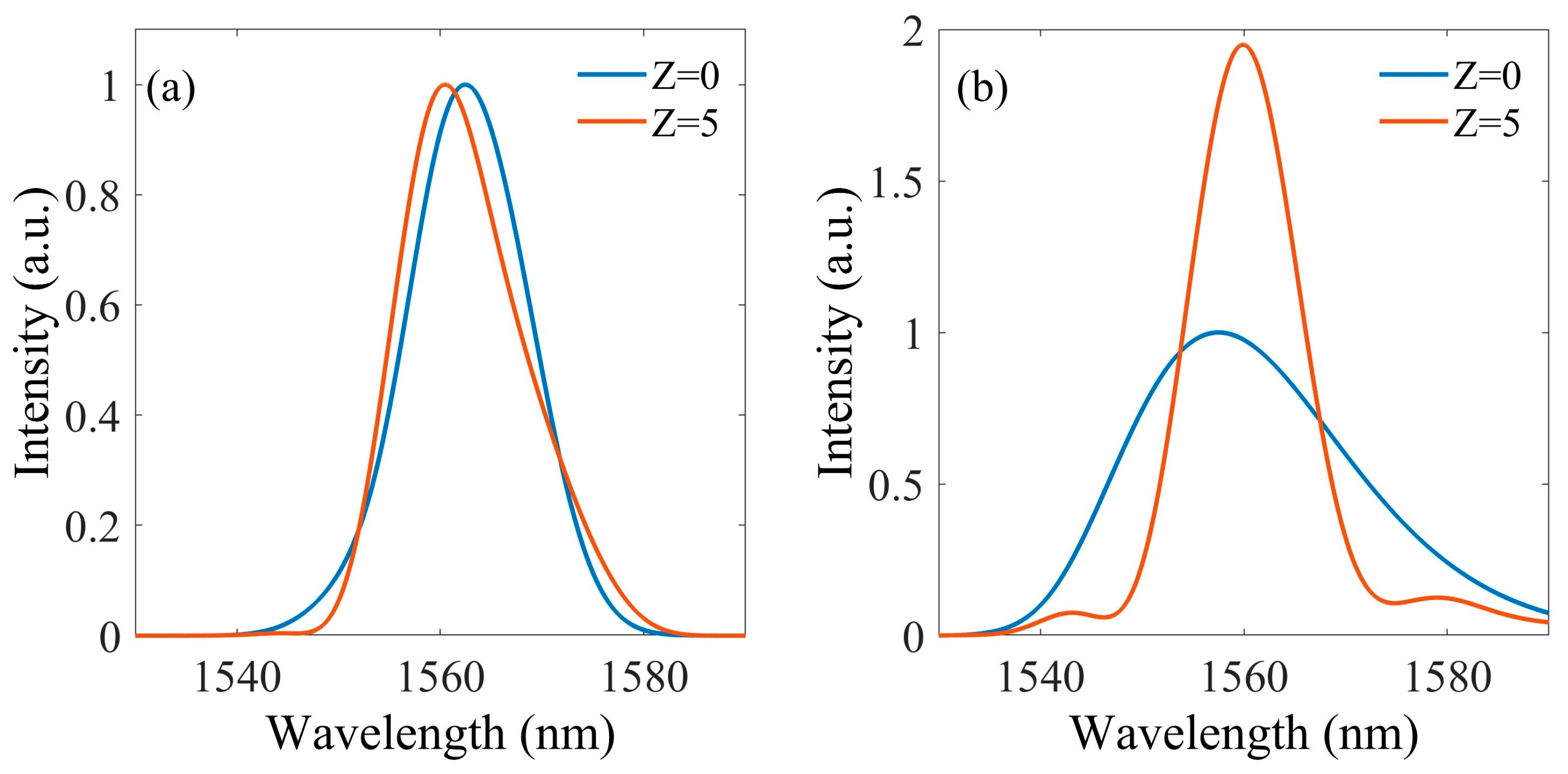
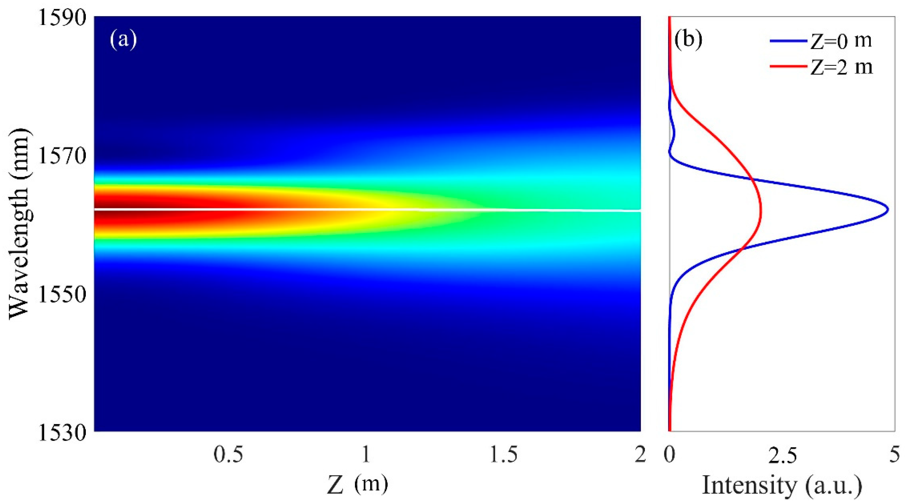
3.3. Influence of Propagation Distance on the Frequency Shift of Asymmetric Pulse

From the evolution dynamics of TAP and SAP, as shown in Figure 2 and Figure 3, it is not hard to find that the frequency shifts are related to the propagation dynamics. As a result, we set the propagation distance as the variation. Here, the maximum propagation distance is set to be 10 m. As the propagation distance is longer, the pulse will exhibit unregular spectral broadening, which displays a multi-peak asymmetric spectrum. This might result from the strong nonlinear phase shift. As a result, it is difficult to mark the peak wavelength. As shown in Figure 4a, for TLAP, the peak wavelength shifts are related to the propagation distance. For an intensity-dependent parameter lower than 1.05, the peak wavelength shift is limited. For an intensity-dependent parameter higher than 1.05, the peak wavelength shift range increases obviously during the propagation. The maximum peak wavelength shift is about 8.4 nm, with Z = 4.2 m and a = 2.5. Although, if the intensity-dependent parameter is much higher than 2.5, the frequency shift might be bigger. The spectrum displays multi-peaks with excessive nonlinear phase shifts. Meanwhile, the peak wavelength might not be a center wavelength. As a result, the maximum intensity-dependent parameter here is limited to 2.5. Therefore, we can infer that if we select the TLAP as the input pulse, the propagation distance should be carefully optimized. Note that there exists some discontinuity if the intensity-dependent parameter and propagation distance are all large enough. For instance, if the propagation distance is about 4.2 m and the intensity-dependent parameter is about 2.5, the spectrum displays multi-peaks, indicating that the excessive nonlinear phase shifts are beyond the restraint of the asymmetry phase.
As shown in Figure 4b, for SRAP, the peak wavelength shift shows the different characteristics in comparison with TLAP. With increasing the launched pulse intensity and propagation distance, the peak wavelength can be shifted to the longer wavelength. Here, the maximum peak wavelength shift is about 6.78 nm when Z = 10 m and a = 2.5. Compared with these two situations, it is easy to find here that the frequency shifts for SRAP are always larger than those of TLAP, indicating that the application for SRAP has more advantages in the terms of the spectral continuous tuning range. It should be noted that the dispersion of the optical medium here is normal. If the dispersion is negative, the propagation dynamics are different, which is discussed in the following section.
Under certain suitable conditions, an interesting phenomenon can be observed. The peak wavelength shift can show the blueshift or remain nearly unchanged within a certain distance, as shown in the region marked by the white line in Figure 4b for SRAP. To clearly exhibit the propagation dynamics of these special situations, we set the propagation distance as Z = 2 m and a = 2.2. As shown in Figure 5a, although the spectrum undergoes broadening, the peak wavelength remains unchanged. The initial and final spectrum can be seen in Figure 5b. We can easily find that the propagation dynamics of the peak wavelength are similar to those of the symmetric pulse. This evolution process resulted from the balance between the initial nonlinear chirp, nonlinearity, and SPM-induced nonlinear phase shift. As the initial chirp is a positive parabolic-like nonlinear chirp, as shown in Figure 1c, it cannot be compensated by the nonlinear phase shift. As a result, it appears as the weakness of the spectral asymmetry that the peak wavelength approaches the center wavelength with spectral narrowing. Therefore, the spectrum displays a blueshift.

3.4. Influence of Dispersion on the Propagation of Asymmetric Pulse

As shown in Figure 6, the influence of dispersion of the optical medium on the propagation of the asymmetric pulse can be found. Here, the propagation distance is set to be 5 m. For TLAS, as depicted in Figure 6a, with the increase of normal dispersion, the frequency shift process would be weakened, as the larger dispersion can lower the peak power by stretching the pulse. When the intensity-dependent parameter is lower than 1.1, the peak wavelength shift always maintains a low level. As the intensity-dependent parameter is increasing, the spectra show a stronger redshift. The maximum peak wavelength shift is about 14.8 nm, while a = 2 and dispersion of the optical medium as zero. Note that here, the dispersion is set as normal. When dispersion is negative, the asymmetric pulse suffers from the pulse splitting under a low peak power due to an uncompensated nonlinear phase shift. As a result, the obvious self-frequency shift cannot be achieved because the peak wavelength is uncertain.
For SRAP, as shown in Figure 6b, the spectra will exhibit the blueshift or redshift under the distinct dispersion condition as well as the peak intensity. A clear boundary can be seen as the white line in Figure 6b, and the boundary means that the peak wavelength remains unchanged. At the right side of the boundary, the frequency shift always remains positive, indicating that the spectra display a redshift. With a = 2 and β2 = 5 ps2/km, the maximum wavelength shift is ~4.28 nm. At the left side of the boundary, the blueshift can be achieved. With a = 0.5 and β2 = 25 ps2/km, the maximum wavelength shift is ~−7.53 nm. The formation mechanism of the evolution can be explained with the process shown in Figure 3. As we noted before, the asymmetric nonlinear phase shift is dependent on the pulse intensity. For the situation of the left boundary, the nonlinear phase shift generated from the SPM effect is stronger than that of the linear shift from optical medium dispersion. However, the initial chirp is a positive parabolic-like nonlinear chirp, as shown in Figure 1c, and it cannot be compensated by the nonlinear phase shift. As a result, it appears as the weakness of the spectral asymmetry that the peak wavelength approaches the center wavelength with spectral narrowing. Therefore, the spectrum displays a blueshift. On the contrary, for the situation of the left boundary, the spectrum displays a redshift. While the asymmetric nonlinear phase is balanced with initial chirp and linear shift, the peak wavelength remains unchanged.

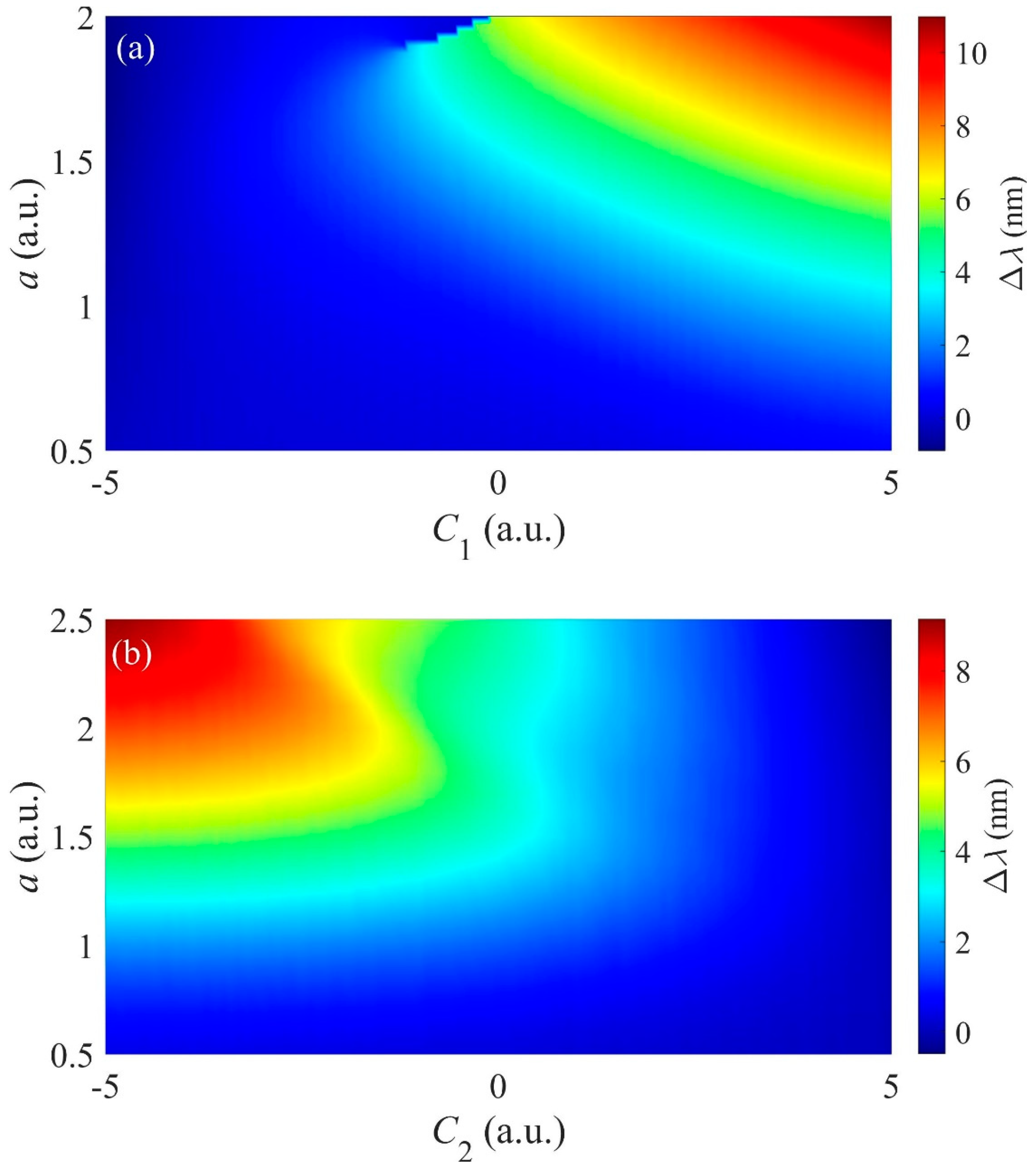
3.5. Influence of Initial Chirp on the Propagation of Asymmetric Pulse

As the propagation dynamics of the asymmetric pulse are quite sensitive to the nonlinear phase shift, the initial chirp of the asymmetric pulse plays an important role for the peak wavelength shift as well. Therefore, we changed the initial chirp without changing other parameters. It should be noted that we changed the initial chirp by additional chirps (C1 or C2). Here, C1 or C2 are normalized chirp parameters [13]. As the initial chirp is changed, the compensable nonlinear phase shift is varied as well. As the initial chirp of TLAP is zero, the corresponding spectrum shows Gaussian-like symmetry. However, if the initial chirp is nonzero, the corresponding spectrum is asymmetric. As shown in Figure 7a, it is easy to find that as C1 is negative, the peak wavelength shifts maintain a low level, while the intensity-dependent parameter increases. However, if C1 is positive, it shows a strong redshift. Meanwhile, with increasing the intensity-dependent parameter and initial chirp, the peak wavelength shift increases as well. The maximum peak wavelength shift is about 11 nm, while a = 2 and C1 = 5. Note that when the initial chirp is near zero, there exists some discontinuity if the intensity-dependent parameter is large enough, which corresponds to a multi-peak spectrum as well. This can be attributed to the strong nonlinear phase shift generated from the SPM effect. If the peak wavelength is strong enough, the SPM effect will induce a multi-peak, which is similar to that of SPM-enabled spectral selection [21].
For the SRAP, the propagation dynamics are opposite to those of TLAP, as shown in Figure 7b. As the additional chirp (C2) is positive, SRAP exhibits a redshift while the peak frequency shift is unsensitive to the launched pulse intensity. However, the peak wavelength shift is largely enhanced as the initial chirp and intensity-dependent parameter decrease. The maximum peak wavelength shift is about 9.2 nm, while a = 2 and C1 = 5. Meanwhile, the peak wavelength shift is directly nonlinear proportional to the initial chirp. This result is different from the effect of optical medium dispersion and propagation distance. For the temporal-asymmetric pulse, as shown in Figure 7a, the frequency shift is almost linear proportional to the initial chirp and peak power. However, for the spectral-asymmetric pulse, the frequency shift displays a nonlinear pattern while the C1 is negative, as shown in Figure 7b. This might be originated from the initial positive parabolic-like nonlinear chirp. Although the additional negative chirp, C1, is linearly varying, the total chirp is changed nonlinearly.

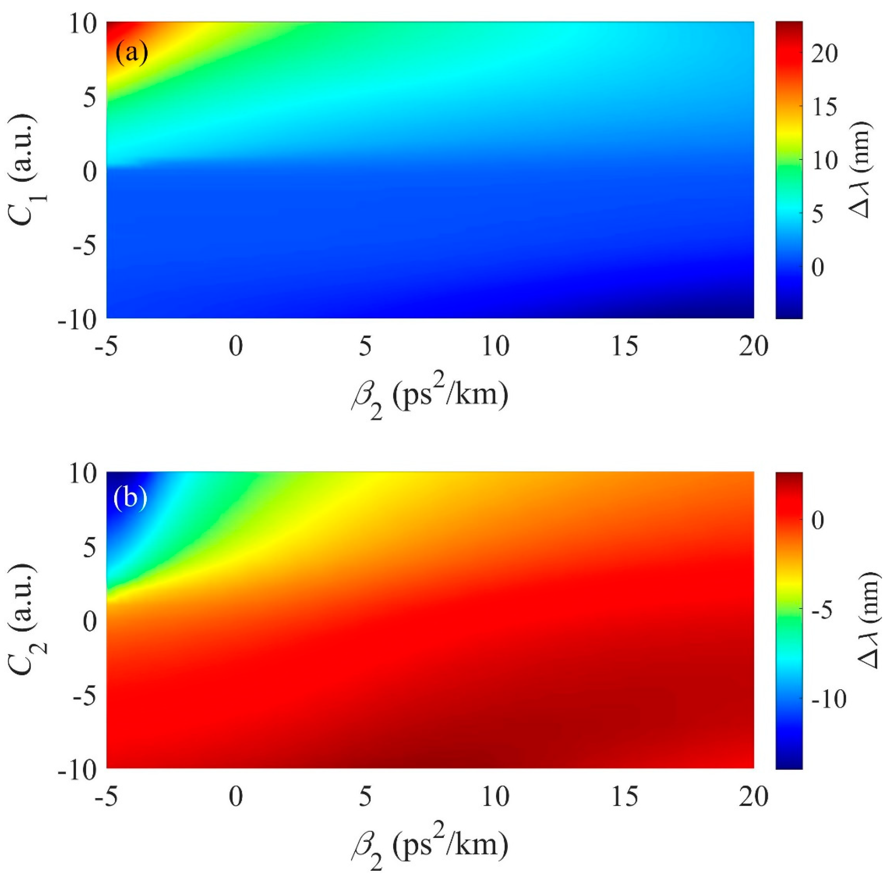
3.6. Influence of Dispersion and Initial Chirp on the Propagation of Asymmetric Pulse

As we discussed before, both initial chirp and dispersion of optical medium can effectively affect the frequency shift of the asymmetric pulse. Therefore, if we take those two factors into account, the phenomena of frequency shift might be enhanced. The propagation distance is set to be 5 m, while the intensity-dependent parameter is set to be 1. As depicted in Figure 8a, for TLAP, when the initial chirp is negative, the peak wavelength displays a slight blueshift, which is determined by the chirp shaping the pulse profile and frequency distribution. This can be attributed to spectral narrowing induced by the inverse four-wave mixing [36].
As shown in Figure 9a,b, when the initial chirp is about −7, the temporal profiles and spectra of the temporal-asymmetric pulse undergo narrowing and broadening, while the spectrum bandwidth has no significant change. Due to the balance between the dispersion of optical medium and initial chirp, the spectrum bandwidth can remain almost unchanged with an obvious frequency shift. The peak wavelength shifts about −1.9911 nm, which is limited by the spectral width of the initial pulse. Moreover, if the initial chirp is positive, the peak wavelength shift has a nearly linear relation to the optical medium dispersion. It is not hard to find that the maximum peak wavelength shift is about 22 nm when the optical medium dispersion is −5 ps2/km and the initial chirp is 10. As the optical medium dispersion is negative, the pulse undergoes pulse compression, leading to a stronger pulse intensity. Moreover, as the initial chirp is positive, the generated nonlinear phase shift can induce the asymmetrical spectral broadening as well. As a result, the frequency shift is enhanced.
For SRAP, as shown in Figure 8b, the spectra exhibit a blueshift and a redshift as well, with appropriate initial chirp and optical medium dispersion. It is easy to find that if the initial chirp is negative, the frequency shift always remains positive, indicating that the spectra display a redshift. This result is similar to that of the temporal-asymmetric pulse, which maintains a slight blueshift. The detailed propagation dynamics can be seen in Figure 9c,d, while the optical medium dispersion is −1 ps2/km and the initial chirp is −20. The bandwidth of the final spectrum decreases into almost half of the initial bandwidth. Meanwhile, the peak wavelength shifts about 2.39 nm, as shown in Figure 10b. If the initial chirp is positive, the peak wavelength shift has to do with the initial chirp and dispersion of optical medium. Meanwhile, as the dispersion of optical medium is gradually moving towards the region of negative dispersion, the spectrum also gradually shifts from a redshift to a blueshift.

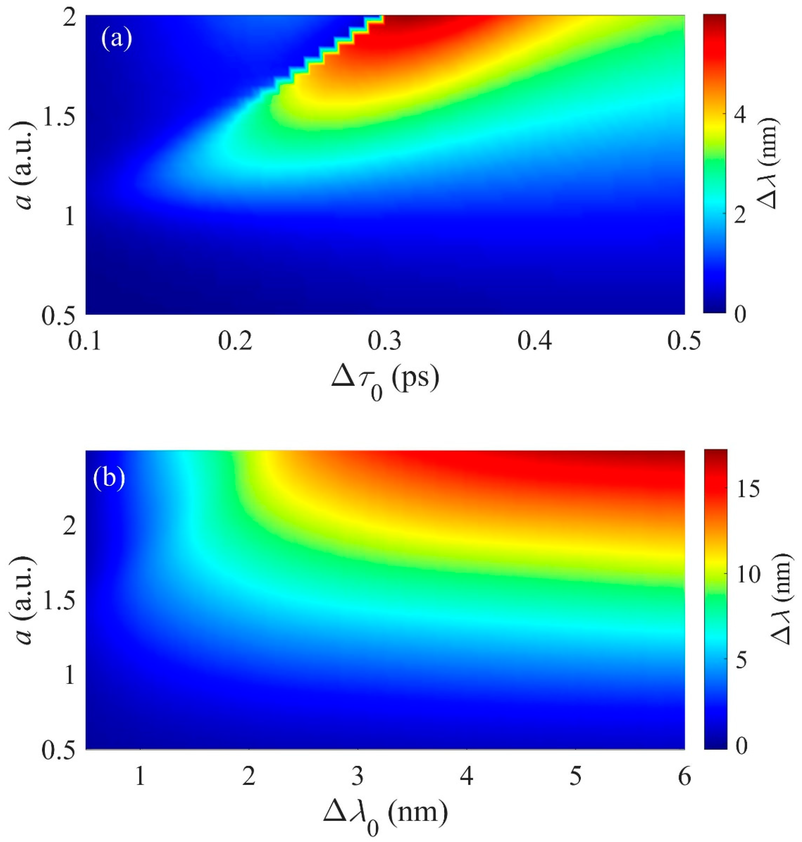
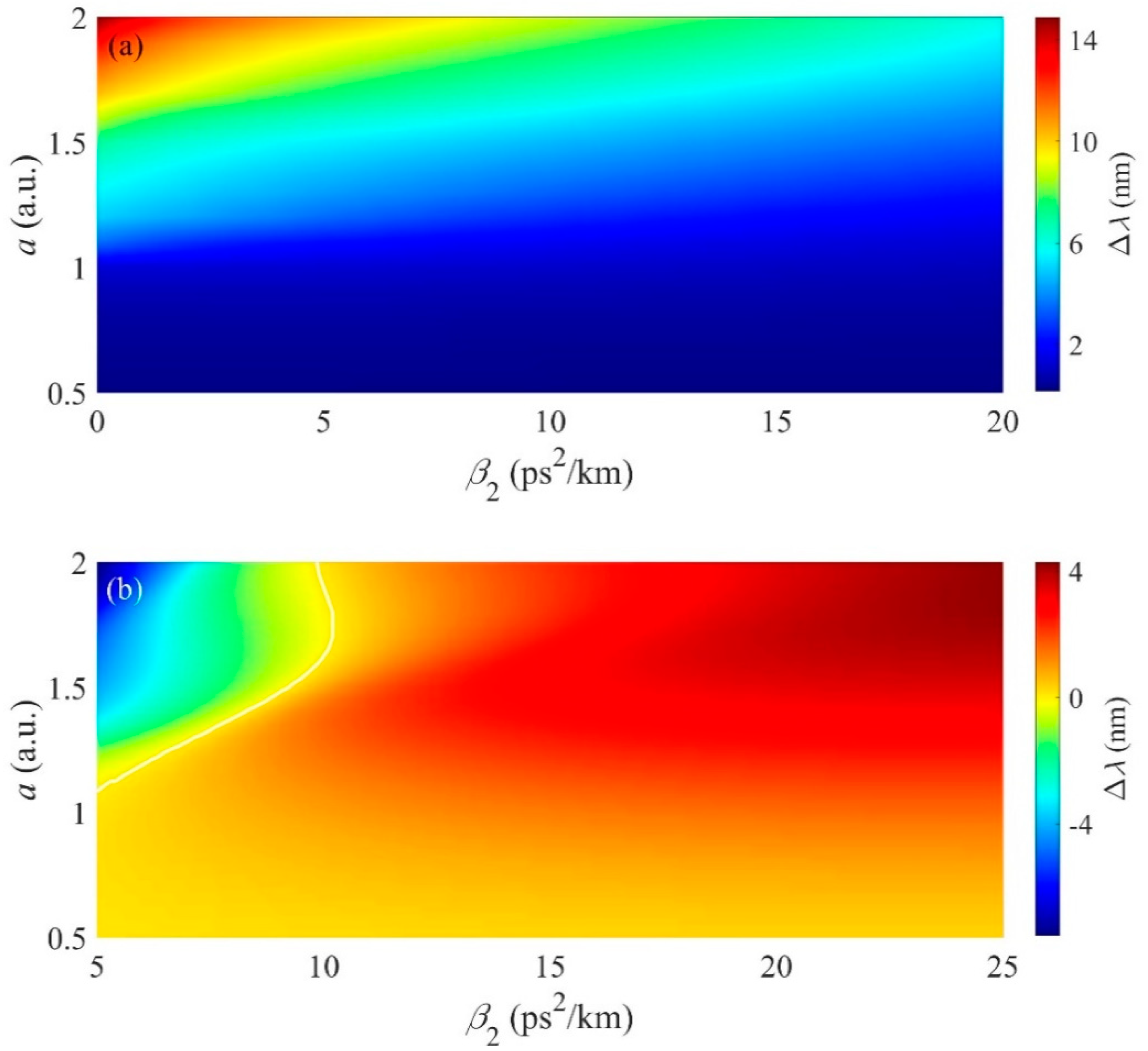
3.7. Influence of Asymmetry Ratio on the Propagation of Asymmetric Pulse

For the asymmetric pulse, the influence of the asymmetry ratio on the propagation dynamics should also be considered. For a simple description of the asymmetry ratio, we defined the initial temporal offset (Δτ0) and peak wavelength offset (Δλ0) as the temporal and spectral asymmetry ratio, respectively. The propagation dynamics between the asymmetry ratio and the intensity-dependent parameter can be seen in Figure 11. As shown in Figure 11a, for TLAP, the influence of the initial temporal offset on the spectral shift is not obvious, which is similar to that of the propagation distance. The maximum peak wavelength shift is about 6 nm when Δτ0 = 0.3 ps and a = 2. The initial peak wavelength offset has a big impact on the spectral shift, as shown in Figure 11b. For SRAP, the peak wavelength shift is directly proportional to the initial peak wavelength offset.
In general, the nonlinear transmission of the optical pulse is always an important research area and provides several methods to control the pulse feature, such as self-parameter amplification, self-similar evolution, modulation instability, and supercontinuum generation [36,37]. Our finding of the propagation dynamics for asymmetric pulses originates from the ubiquity of asymmetric pulses in nonlinear optics and might change the general conception and method in pulse characterization, transmission, and regulation. In fact, the pulse intensity, initial chirp, dispersion of optical medium, and asymmetry ratio can work in combination for the frequency shift, which is more efficient for practical application. Meanwhile, these factors also interact with each other. For an intensity-dependent parameter of 1.05, initial chirp of 10, dispersion of optical medium of −5 ps2/km, and asymmetry ratio of 0.3 ps, the maximum peak wavelength shift can be 24.53 nm for the temporal-asymmetric pulse. The spectral-asymmetric pulse displays no such peak wavelength shift. The simulated results indicate that input nonlinear pulses with properly tailored chirp or intensity can produce self-frequency shift pulses with high conversion efficiency as well as a large tuning range. Since these frequency shift curves are predicted by numerical simulation, one might raise the question of whether they are feasible experimentally. Compared with the traditional Raman frequency shift, the asymmetric pulse can achieve a redshift or a blueshift. Unlike the SPM-enabled spectral selection technique, the nonlinear wavelength conversion might be improved. Considered for the possible experimental implementation, the input asymmetric pulse and suitable propagation fiber or optical medium should be carefully chosen. For generating the asymmetric pulse, a Mach–Zehnder fiber structure composed of a time delay line or liquid crystal phase modulator can be employed to program the initial pulse shape and chirp. Moreover, chirped fiber Bragg grating has been widely used for adjusting the chirp of the pump pulses in chirped pulse oscillation or chirped pulse amplification systems [38,39]. Besides optical fibers, on-chip waveguides might be another choice for nonlinear frequency shifts [40]. The waveguide structure can be precisely engineered to achieve a varied waveguide dispersion along with the direction of propagation to produce a desired spectrum.

4. Conclusions

In summary, we have numerically investigated the nonlinear propagation of an asymmetric pulse in optical medium without emphasis on the role of high-order linear or nonlinear effects. The asymmetry was studied in both the time domain and the frequency domain. It was shown that the peak wavelength of the asymmetric pulse exhibited a redshift or a blueshift in the spectral domain, while it slowed down or sped up in the temporal domain with an obvious bending trajectory. Our results demonstrate that the self-induced frequency shift initiated by a temporal or spectral asymmetric pulse depends not only on the intensity-dependent parameter, but also on the initial pulse chirp. In addition, we also presented the influence of dispersion of optical medium and the asymmetric ratio on the nonlinear propagation of the asymmetric pulse, showing that the spectral-asymmetric pulse has more advantages in terms of the spectral continuous tuning range. These excellent numerical results obtained here may lead to the realization of a frequency shift-based tunable light source by launching the asymmetric pulse into an optical medium, and will find important applications in multiphoton microscopy and the generation of high-power, long-wave, mid-infrared femtosecond pulses.

Author Contributions

Data curation and visualization, Y.Z.; formal analysis and investigation, Y.Z. and Y.C.; investigation and discussion, L.H., B.Z. and D.C.; methodology and writing—original draft, Y.Z. and Y.C.; project administration and funding acquisition, Y.C. All authors have read and agreed to the published version of the manuscript.

Funding

This research was partially supported by National Natural Science Foundation of China under Grant No. 61705193, the Natural Science Foundation of Zhejiang Province under Grant Nos. LY19F050014 and LGG20F050002, the Open Project Program of Wuhan National Laboratory for Optoelectronics under Grant No. 2020WNLOKF008, and the Independent Project by Zhejiang Normal University under Grant No. 2021ZS05.

Institutional Review Board Statement

Not applicable.

Informed Consent Statement

Not applicable.

Data Availability Statement

Not applicable.

Conflicts of Interest

The authors declare no conflict of interest. The funders had no role in the design of the study; in the collection, analyses, or interpretation of data; in the writing of the manuscript, or in the decision to publish the results.

References

  1. Ankiewicz, A.; Akhmediev, N. Dissipative Solitons: From Optics to Biology and Medicine; Springer: Berlin/Heidelberg, Germany, 2008; ISBN 978-3-540-78216-2. [Google Scholar]
  2. Haus, H.A.; Wong, W.S. Solitons in optical communications. Rev. Mod. Phys. 1996, 68, 423. [Google Scholar] [CrossRef]
  3. Keller, U. Recent developments in compact ultrafast lasers. Nature 2003, 424, 831–838. [Google Scholar] [CrossRef] [PubMed]
  4. Kerse, C.; Kalaycloĝ Lu, H.; Elahi, P.; Çetin, B.; Kesim, D.K.; Akçaalan, Ö.; Yavaş, S.; Aşlk, M.D.; Öktem, B.; Hoogland, H.; et al. Ablation-cooled material removal with ultrafast bursts of pulses. Nature 2016, 537, 84–88. [Google Scholar] [CrossRef] [PubMed]
  5. Mollenauer, L.F.; Stolen, R.H.; Gordon, J.P. Experimental observation of picosecond pulse narrowing and solitons in optical fibers. Phys. Rev. Lett. 1980, 45, 1095–1098. [Google Scholar] [CrossRef]
  6. Fermann, M.E.; Hartl, I. Ultrafast fibre lasers. Nat. Photon. 2013, 7, 868–874. [Google Scholar] [CrossRef]
  7. Malomed, B.A. Bound solitons in the nonlinear Schrödinger-Ginzburg-Landau equation. Phys. Rev. A 1991, 44, 6954–6957. [Google Scholar] [CrossRef]
  8. Akhmediev, N.; Soto-Crespo, J.M.; Town, G. Pulsating solitons, chaotic solitons, period doubling, and pulse coexistence in mode-locked lasers: Complex Ginzburg-Landau equation approach. Phys. Rev. E 2001, 63, 056602. [Google Scholar] [CrossRef] [Green Version]
  9. Anderson, D.; Lisak, M. Nonlinear asymmetric pulse distortion in long optical fibers. Opt. Lett. 1982, 7, 394–396. [Google Scholar] [CrossRef]
  10. Yang, G.; Shen, Y.R. Spectral broadening of ultrashort pulses in a nonlinear medium. Opt. Lett. 1984, 9, 510–512. [Google Scholar] [CrossRef]
  11. Anderson, D.; Lisak, M. Nonlinear asymmetric self-phase modulation and self-steepening of pulses in long optical waveguides. Phys. Rev. A 1983, 27, 1393. [Google Scholar] [CrossRef]
  12. Gomes, A.S.L.; Hickmann, J.M.; de Oliveira, J.R.; de Moura, M.A. Self-steepening of optical pulses in dispersive media. J. Opt. Soc. Am. B 1992, 9, 2025–2027. [Google Scholar] [CrossRef]
  13. Agrawal, G.P. Nonlinear Fiber Optics; Academic Press: New York, NY, USA, 2007; ISBN 9780123695161. [Google Scholar]
  14. Radhakrishnan, R.; Lakshmanan, M. Exact soliton solutions to coupled nonlinear Schrödinger equations with higher-order effects. Phys. Rev. E 1996, 54, 2949. [Google Scholar] [CrossRef] [PubMed]
  15. Dudley, J.M.; Genty, G.; Coen, S. Supercontinuum generation in photonic crystal fiber. Rev. Mod. Phys. 2006, 78, 1135–1184. [Google Scholar] [CrossRef]
  16. Nishizawa, N.; Goto, T. Compact System of Wavelength-Tunable Femtosecond Soliton Pulse Generation Using Optical Fibers. IEEE Photonics Technol. Lett. 1999, 11, 325–327. [Google Scholar] [CrossRef]
  17. Blow, K.J.; Wood, D. Theoretical Description of Transient Stimulated Raman Scattering in Optical Fibers. IEEE J. Quantum Electron. 1989, 25, 2665–2673. [Google Scholar] [CrossRef]
  18. Stolen, R.H.; Tomlinson, W.J. Effect of the Raman part of the nonlinear refractive index on propagation of ultrashort optical pulses in fibers. J. Opt. Soc. Am. B 1992, 9, 565–573. [Google Scholar] [CrossRef]
  19. Bugay, A.N.; Khalyapin, V.A. Analytic description of Raman-induced frequency shift in the case of non-soliton ultrashort pulses. Phys. Lett. A 2017, 381, 399–403. [Google Scholar] [CrossRef]
  20. Agrawal, G.P. Modulation instability induced by cross-phase modulation. Phys. Rev. Lett. 1987, 59, 880. [Google Scholar] [CrossRef]
  21. Diao, X.; Diao, X.; Chen, R.; Chen, R.; Chang, G.; Chang, G.; Chang, G. Particle swarm optimization of SPM-enabled spectral selection to achieve an octave-spanning wavelength-shift. Opt. Express 2021, 29, 39766–39776. [Google Scholar] [CrossRef]
  22. Hua, Y.; Hua, Y.; Zhou, G.; Zhou, G.; Liu, W.; Liu, W.; Xin, M.; Kärtner, F.X.; Kärtner, F.X.; Chang, G. Femtosecond two-color source synchronized at 100-as-precision based on SPM-enabled spectral selection. Opt. Lett. 2020, 45, 3410–3413. [Google Scholar] [CrossRef]
  23. Xiang, Y.; Dai, X.; Wen, S.; Guo, J.; Fan, D. Controllable Raman soliton self-frequency shift in nonlinear metamaterials. Phys. Rev. A 2011, 84, 033815. [Google Scholar] [CrossRef] [Green Version]
  24. Bendahmane, A.; Kudlinski, A.; Mussot, A.; Vanvincq, O. Control of the soliton self-frequency shift dynamics using topographic optical fibers. Opt. Lett. Vol. 2013, 38, 3390–3393. [Google Scholar] [CrossRef] [PubMed]
  25. Saleh, M.F.; Chang, W.; Hölzer, P.; Nazarkin, A.; Travers, J.C.; Joly, N.Y.; Russell, P.S.J.; Biancalana, F. Theory of photoionization-induced blueshift of ultrashort solitons in gas-filled hollow-core photonic crystal fibers. Phys. Rev. Lett. 2011, 107, 203902. [Google Scholar] [CrossRef]
  26. Facão, M.; Carvalho, M.I.; Almeida, P. Accelerating solitons in gas-filled hollow-core photonic crystal fibers. Phys. Rev. A 2013, 87, 063803. [Google Scholar] [CrossRef] [Green Version]
  27. Bugay, A.N.; Khalyapin, V.A. Analytic description of pulse frequency self-shift in nonlinear photonic crystal fibers. Commun. Nonlinear Sci. Numer. Simul. 2019, 75, 270–279. [Google Scholar] [CrossRef]
  28. Zhang, L.; Zhong, H.; Li, Y.; Fan, D. Manipulation of Raman-induced frequency shift by use of asymmetric self-accelerating Airy pulse. Opt. Express 2014, 22, 22598–22607. [Google Scholar] [CrossRef]
  29. Cui, Y.; Zhang, Y.; Song, Y.; Huang, L.; Tong, L.; Qiu, J.; Liu, X. XPM-Induced Vector Asymmetrical Soliton with Spectral Period Doubling in Mode-Locked Fiber Laser. Laser Photon. Rev. 2021, 15, 2000216. [Google Scholar] [CrossRef]
  30. Guo-Yan, Y.; Jiang-Bo, Z.; Xiao-Yu, Y.; Liang-Wei, D. Asymmetrical surface soliton trains. Chin. Phys. B 2010, 19, 044206. [Google Scholar] [CrossRef]
  31. Guan, W.Y.; Li, B.Q. Asymmetrical and self-similar structures of optical breathers for the Manakov system in photorefractive crystals and randomly birefringent fibers. Optik 2019, 194, 162882. [Google Scholar] [CrossRef]
  32. Chen, S.-C.; Liu, C.; Yao, X.; Zhao, L.-C.; Akhmediev, N. Extreme spectral asymmetry of Akhmediev breathers and Fermi-Pasta-Ulam recurrence in a Manakov system. Phys. Rev. E 2021, 104, 024215. [Google Scholar] [CrossRef]
  33. Akhmediev, N.; Soto-Crespo, J.M. Strongly asymmetric soliton explosions. Phys. Rev. E 2004, 70, 036613. [Google Scholar] [CrossRef] [PubMed] [Green Version]
  34. Pakarzadeh, H.; Delirian, Z.; Taghizadeh, M. Simulation of Chirped Pulse Propagation in Silicon Nanowires: Shape and Spectrum Analysis. Opt. Photonics J. 2016, 06, 53–61. [Google Scholar] [CrossRef] [Green Version]
  35. Bourkoff, E.; Zhao, W.; Joseph, R.I.; Christodoulides, D.N. Intensity-dependent spectra of pulses propagating in optical fibers. Opt. Commun. 1987, 62, 284–288. [Google Scholar] [CrossRef]
  36. Turitsyn, S.K.; Bednyakova, A.E.; Fedoruk, M.P.; Papernyi, S.B.; Clements, W.R.L. Inverse four-wave mixing and self-parametric amplification in optical fibre. Nat. Photon. 2015, 9, 608–614. [Google Scholar] [CrossRef] [Green Version]
  37. Dudley, J.M.; Finot, C.; Richardson, D.J.; Millot, G. Self-similarity in ultrafast nonlinear optics. Nat. Phys. 2007, 3, 597–603. [Google Scholar] [CrossRef]
  38. Želudevičius, J.; Regelskis, K.; Danilevičius, R. Optimization of pulse compression in a fiber chirped pulse amplification system by adjusting dispersion parameters of a temperature-tuned chirped fiber Bragg grating stretcher. J. Opt. Soc. Am. B 2015, 32, 812–817. [Google Scholar] [CrossRef]
  39. Brinkmann, M.; Hellwig, T.; Fallnich, C. Optical parametric chirped pulse oscillation. Opt. Express 2017, 25, 12884–12895. [Google Scholar] [CrossRef]
  40. Ciret, C.; Gorza, S.-P. Generation of ultra-broadband coherent supercontinua in tapered and dispersion-managed silicon nanophotonic waveguides. J. Opt. Soc. Am. B 2017, 34, 1156–1162. [Google Scholar] [CrossRef] [Green Version]
Figure 1. Temporal−spectral properties of the input pulse. (a) Temporal intensity profile and chirp of initial TAP. (b) Corresponding symmetric spectrum of initial pulse. (c) Temporal symmetric intensity profile and chirp of initial SAP. (d) Corresponding asymmetric spectrum of initial pulse.
Symmetry 14 00834 g001
Figure 2. Temporal and spectral evolution dynamics of the TAP in the normal dispersion regime (a = 2): (a,b) left−asymmetric pulse and (c,d) right−asymmetric pulse. The white line in (a,c) indicates the temporal shift, and the white line in (b,d) shows the frequency shift.
Symmetry 14 00834 g002
Figure 3. Temporal and spectral evolution dynamics of the spectral−asymmetric pulse in the normal dispersion regime (a = 2): (a,b) spectral right−asymmetric pulse and (c,d) spectral left−asymmetric pulse. The white line in (a,c) indicates the temporal shift, and the white line in (b,d) shows the frequency shift.
Symmetry 14 00834 g003
Figure 4. (a) Frequency shifts (Δλ) of TLAP with different intensity−dependent parameters as a function of propagation distance (Z). (b) Frequency shifts (Δλ) of SRAP with different intensity−dependent parameters as a function of propagation distance (Z). The white line denotes that the frequency offset is zero.
Symmetry 14 00834 g004
Figure 5. (a) Spectral evolution dynamics of the SRAS with propagation distance as 2 and a = 2.2. (b) Initial spectrum and final spectrum. The white line denotes the peak wavelength.
Symmetry 14 00834 g005
Figure 6. (a) Frequency shifts (Δλ) of TLAP with different intensity−dependent parameters as a function of dispersion (β2). (b) Frequency shifts (Δλ) of SRAP with different intensity−dependent parameters as a function of dispersion (β2). The white line denotes that the frequency offset is zero.
Symmetry 14 00834 g006
Figure 7. (a) Frequency shift (Δλ) of TLAP with different intensity−dependent parameters as a function of additional chirp (C1). (b) Frequency shift (Δλ) of SRAP with different intensity−dependent parameters as a function of additional chirp (C2).
Symmetry 14 00834 g007
Figure 8. (a) Frequency shift (Δλ) dynamics of TLAP as a function of additional chirp (C1) and dispersion (β2). (b) Frequency shift (Δλ) dynamics of SRAP as a function of additional chirp (C2) and dispersion (β2).
Symmetry 14 00834 g008
Figure 9. Temporal and spectral evolution dynamics of the asymmetric pulse in the normal dispersion regime: (a,b) temporal-asymmetric pulse and (c,d) spectral−asymmetric pulse. The white line denotes the peak wavelength.
Symmetry 14 00834 g009
Figure 10. Final spectra and initial spectra for (a) temporal-asymmetric pulse and (b) spectral-asymmetric pulse.
Symmetry 14 00834 g010
Figure 11. (a) Frequency shifts (Δλ) of the temporal−asymmetric pulse with different intensity−dependent parameters as a function of initial temporal offset. (b) Frequency shifts (Δλ) of the spectral−asymmetric pulse with different intensity-dependent parameters as a function of initial peak wavelength offset.
Symmetry 14 00834 g011
Publisher’s Note: MDPI stays neutral with regard to jurisdictional claims in published maps and institutional affiliations.

