Article

Magnetic Circuit Analysis of Halbach Array and Improvement of Permanent Magnetic Adsorption Device for Wall-Climbing Robot

School of Mechanical Engineering, Hebei University of Technology, Tianjin 300130, China
*
Author to whom correspondence should be addressed.
Symmetry 2022, 14(2), 429; https://doi.org/10.3390/sym14020429
Submission received: 4 February 2022 / Revised: 15 February 2022 / Accepted: 19 February 2022 / Published: 21 February 2022

Abstract

:
To solve the problems that the theoretical analysis of Halbach array magnetic circuit is insufficient and that calculating the magnetic adsorption force of a permanent magnet by using the magnetic node method is complex, the magnetic flux density of a Halbach array magnetic circuit composed of multiple permanent magnets with perpendicular magnetization directions is calculated. On the basis of the concentrated magnetic phenomenon of the ferromagnetic material and the end effect of the permanent magnet, a method for calculating the magnetic adsorption force of the Halbach array magnetic circuit by using the equivalent magnetic flux density is proposed, and the variation trend of magnetic adsorption force after changing the parameters of the magnetic circuit is obtained. ANSYS software is used to analyze several magnetic circuits that produce large magnetic adsorption force, a magnetic circuit structure that produces the largest magnetic adsorption force is determined, and the permanent magnetic adsorption device of the wall-climbing robot is improved. The magnetic adsorption force of the wall-climbing robot before and after the improvement of the permanent magnetic adsorption device is measured through experiments. The experimental results show that the magnetic adsorption force after the improvement is increased by 24.63% compared to before the improvement.

1. Introduction

Compared to other adsorption wall-climbing robots (such as negative pressure, thrust, bionic, and electromagnetic adsorption wall-climbing robots), permanent magnetic adsorption wall-climbing robots have the advantages of being safer and more reliable and having a high load–weight ratio [1,2,3,4]. Permanent magnetic adsorption wall-climbing robots can be divided into fixed and adjustable magnetic gap types in accordance with whether the magnetic gap changes when the robot works. A fixed magnetic gap wall-climbing robot can generate large magnetic adsorption force via a small amount of permanent magnets because the permanent magnetic adsorption device is attached to the wall [5,6,7,8,9]. An adjustable magnetic gap wall-climbing robot generally uses a screw to install the permanent magnetic adsorption device on the side of the wall-climbing robot body close to the working surface; the servo motor drives the screw to rotate so as to adjust the distance between the permanent magnetic adsorption device and the working surface to realize the adjustment of the magnetic adsorption force [10]. Compared to a fixed magnetic gap wall-climbing robot, an adjustable magnetic gap wall-climbing robot is easier to be installed and disassembled on the working surface. When the external force changes, dynamic adjustment of the magnetic adsorption force can be realized to ensure that the wall-climbing robot is reliably adsorbed on the working surface and can move flexibly. Wu et al. [11] designed a wall-climbing welding robot with adjustable magnetic adsorption force. The permanent magnetic adsorption device of the wall-climbing welding robot is composed of ten Nd-Fe-B permanent magnets with opposite magnetization directions. Given that the magnetic circuit should be equipped with many magnetic isolation aluminum blocks, the space for installing permanent magnets in the permanent magnetic adsorption device is not fully and reasonably utilized. Hence, the ratio of the adsorption force generated by the magnetic circuit to the self-weight is lower than that in a Halbach array magnetic circuit.
The rudiment of a Halbach array magnetic circuit was first proposed by Professor Mallinson, who studied a one-sided flux magnetic circuit when a single permanent magnet is magnetized in different directions continuously in an ideal state [12]. As it is impossible to magnetize a permanent magnet continuously in different directions in practical engineering, the one-sided flux magnetic circuit cannot be applied to engineering equipment. The Halbach array magnetic circuit, which can be used in engineering, was first discovered by Professor Halbach, and its magnetic field distribution was studied in detail [13]. Currently, the Halbach array magnetic circuit is mainly used in magnetic levitation systems and motor equipment [14,15,16,17] but rarely used in the permanent magnetic adsorption device of wall-climbing robots. Hoburg et al. [18] studied the magnetic field distribution of a Halbach array magnetic levitation system with 45° magnetization direction and obtained the calculation equation of magnetic flux density. However, due to the difficulty in manufacturing magnets with 45° magnetization direction, Halbach array magnetic circuits with 45° magnetization direction are rare in magnetic levitation systems. The magnetic field results are inapplicable to the Halbach array magnetic circuits with perpendicular magnetization directions. Meessen et al. [19] studied a cylindrical Halbach array magnetic circuit applied to a rotary electric machine and obtained an analytical solution for magnetic flux density. At present, the magnetic scalar potential method and the magnetic node method are mainly used to calculate the magnetic flux density of the Halbach array magnetic circuits. Professor Mallinson [12] used the magnetic scalar potential method to analyze a one-sided flux magnetic circuit, but he only analyzed the magnetic field distribution of a single permanent magnet in the ideal state of continuous magnetization in different directions. He did not study a Halbach array magnetic circuit composed of multiple permanent magnets with perpendicular magnetization directions. Qu et al. [20] used the magnetic node method to study two cuboid permanent magnets with parallel magnetization directions and proposed a method to calculate the magnetic force rapidly by combining an analytical model with numerical calculation. Nonetheless, this method still needs to calculate the quadruple integral, and the calculation process is complex. Presently, the most popular method for calculating a Halbach array magnetic circuit is to use finite element software to simulate the designed magnetic circuit [21,22]. It has the advantages of fast calculation speed and high accuracy of the results, but the finite element software cannot independently determine the best magnetic circuit structure. Thus, designers should compare various magnetic circuit results and select the one that is most ideal.
To solve the above problems in the calculation of Halbach array magnetic circuits, the main contents of this paper are as follows: (1) The magnetic scalar potential method combined with Fourier transform is used to study the Halbach array permanent magnet adsorption device of the wall-climbing robot as shown in Figure 1, and the expression of magnetic flux density is obtained. On this basis, the equivalent magnetic flux density is proposed, the end effect of the magnet is considered, and the variation trend of magnetic adsorption force and magnetic circuit parameters is obtained. In the Halbach array magnetic circuit, as shown in Figure 1c, when the number of permanent magnet blocks is odd, the permanent magnet adsorption device has symmetry; when the number of permanent magnet blocks is even, the permanent magnet adsorption device has asymmetry. (2) ANSYS software is used to analyze several magnetic circuits that produce a large magnetic adsorption force, and the Halbach array magnetic circuit that produces the largest magnetic adsorption force is determined. (3) In accordance with the analysis results, the permanent magnetic adsorption device of the wall-climbing robot is improved. The relationship between the adsorption force and the magnetic gap of the permanent magnetic adsorption device before and after improvement is evaluated through experiments.

2. Theoretical Analysis of Halbach Array Magnetic Circuit

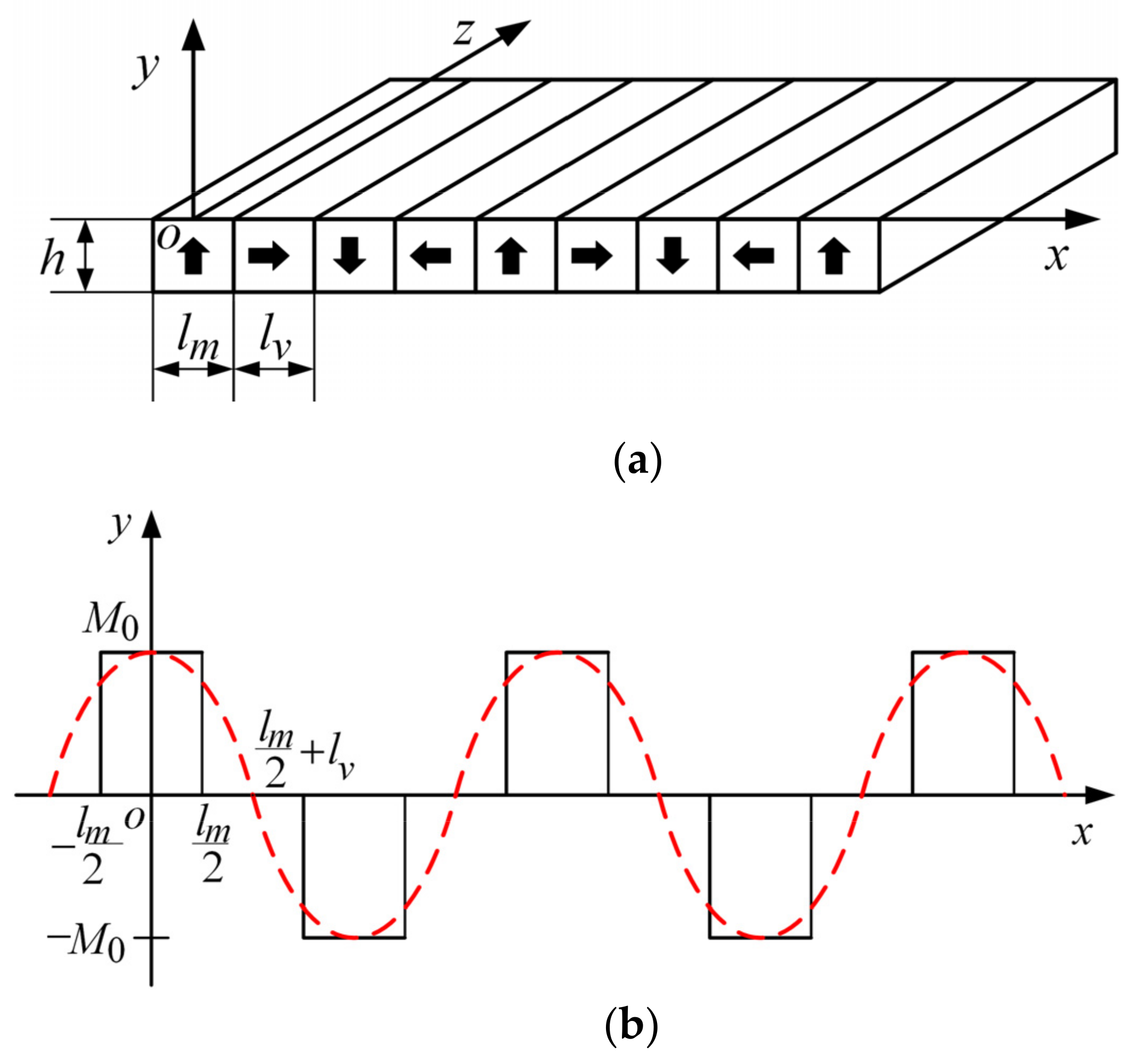
2.1. Establishment of the Mathematical Model of the Magnetic Circuit

The permanent magnetic adsorption device of the wall-climbing robot adopts a Halbach array magnetic circuit, as shown in Figure 2a. In this paper, the magnet whose magnetization direction is parallel to the y-axis is defined as the main magnet, and the magnet whose magnetization direction is parallel to the x-axis is defined as the vice magnet. In the x–y plane, the relationship between the magnetization of the main magnet and the vice magnet and the length of the magnet is shown in Figure 2b,c, respectively. The red dotted line represents the ideal magnetization function.
Referring to Figure 2b,c together, we can express the magnetization intensity functions of the main and vice magnets by Equations (1) and (2), based on the magnetization directions of the main and vice magnets in the Halbach array magnetic circuit.
M Y ( x ) = M 0 ( l m + l v ) x < ( l v + l m 2 ) 0 ( l v + l m 2 ) x < l m 2 M 0 l m 2 x < l m 2 0 l m 2 x < l m 2 + l v M 0 l m 2 + l v x < l m + l v
M X ( x ) = 0 0 x < l m 2 M 0 l m 2 x < l v + l m 2 0 l v + l m 2 x < l v + 3 l m 2 - M 0 l v + 3 l m 2 x < 2 l v + 3 l m 2 0 2 l v + 3 l m 2 x < 2 ( l m + l v )
where M Y ( x ) and M X ( x ) are the magnetization intensity functions of the main magnet and the vice magnet, respectively; M 0 is the magnetization of the permanent magnet; l m and l v are the lengths of the single main magnet and the vice magnet in the x-axis, respectively; and h is the height of the permanent magnet in the y-axis.
As shown in Figure 2a, the magnetization of the permanent magnet in the z-axis is 0, such that M Z ( x ) = 0 . If Equations (1) and (2) are expanded into Fourier series, then
M Y ( x ) = M 0 n = 1 4 n π sin ( n π 2 ) cos [ n l v π 2 ( l m + l v ) ] × cos ( n π x l m + l v )
M X ( x ) = M 0 n = 1 4 n π sin ( n π 2 ) sin [ n l v π 2 ( l m + l v ) ] × sin ( n π x l m + l v )
where n is the harmonic order.
Then, the magnetization M of the Halbach array magnetic circuit can be expressed as
M = M X M Y M Z = n = 1 4 M 0 n π sin n π 2 sin n π l v 2 ( l m + l v ) sin n π x l m + l v n = 1 4 M 0 n π sin n π 2 cos n π l v 2 ( l m + l v ) cos n π x l m + l v 0
For ease of analysis, let
A ( n ) = 4 M 0 n π sin n π 2 sin n π l v 2 ( l m + l v )
B ( n ) = 4 M 0 n π sin n π 2 cos n π l v 2 ( l m + l v )
k ( n ) = n π l m + l v
Then, Equation (5) can be simplified to
M = n = 1 M ( n ) = n = 1 M X ( n ) M Y ( n ) M Z ( n ) = n = 1 A ( n ) sin k ( n ) x B ( n ) cos k ( n ) x 0
In accordance with Maxwell’s equations [23],
× H = J + t ε 0 E
· B = 0
where H is the magnetic field intensity, J is the current density, E is the electric field strength, is the nabla operator, and B is the magnetic flux density.
Given that the Halbach array magnetic circuit is a constant magnetic field problem, no electric field and current density exist, that is, Equation (10) is
× H = 0
Following the relationship between the magnetic field intensity and the magnetic scalar potential in the magnetic field space, we have
H = - φ
where φ is the magnetic scalar potential.
Assuming that the relative permeability of the permanent magnet used in the adsorption device of the wall-climbing robot is 1 and that the relative permeability of Nd-Fe-B is approximately 1.05 [24], then we obtain
B = μ 0 ( H + M )
where μ 0 is the permeability of vacuum, and M is the magnetization of the material.
From Equations (14) and (11), we can obtain
· H = · M
Equation (15) is substituted into Equation (13) to obtain
2 φ p ( n ) = · M = A ( n ) k ( n ) cos k ( n ) x
where φ p is the magnetic scalar potential of the permanent magnet.
Given that the air magnetization is 0, for a weak magnetic field and the strong magnetic side region, one has
2 φ w ( n ) = 0
2 φ s ( n ) = 0
where φ w is the magnetic scalar potential of the weak magnetic field, and φ s is the magnetic scalar potential of the strong magnetic field.
Equations (16)–(18) are Poisson and Laplace equations, and their general solutions are
φ w ( n ) = C 1 e k ( n ) y + C 2 e k ( n ) y cos k ( n ) x φ p ( n ) = C 3 e k ( n ) y + C 4 e k ( n ) y A ( n ) k ( n ) cos k ( n ) x φ s ( n ) = C 5 e k ( n ) y + C 6 e k ( n ) y cos k ( n ) x
where C 1 ~ C 6 are the coefficients to be solved.
The magnetic field boundary condition is given by [25]
φ w ( n ) = φ s ( n ) = 0 y = + φ w ( n ) = φ s ( n ) = 0 y = φ w ( n ) = φ p ( n ) y = 0 φ p ( n ) = φ s ( n ) y = h - φ w ( n ) y = p ( n ) y + B ( n ) cos k ( n ) x y = 0 - φ s ( n ) y = φ p ( n ) y + B ( n ) cos k ( n ) x y = h
The special solutions of Equations (16)–(18) can be obtained from Equation (20) as follows:
φ w = ( A ( n ) B ( n ) ) ( 1 e k ( n ) h ) 2 k ( n ) e k ( n ) h e k ( n ) y cos k ( n ) x φ p = ( A ( n ) B ( n ) ) ( 1 e k ( n ) h ) 2 k ( n ) e k ( n ) h + ( A ( n ) + B ( n ) ) e k ( n ) y 2 k ( n ) - A ( n ) k ( n ) cos k ( n ) x φ s = ( A ( n ) + B ( n ) ) ( 1 e k ( n ) h ) 2 k ( n ) e k ( n ) y cos k ( n ) x

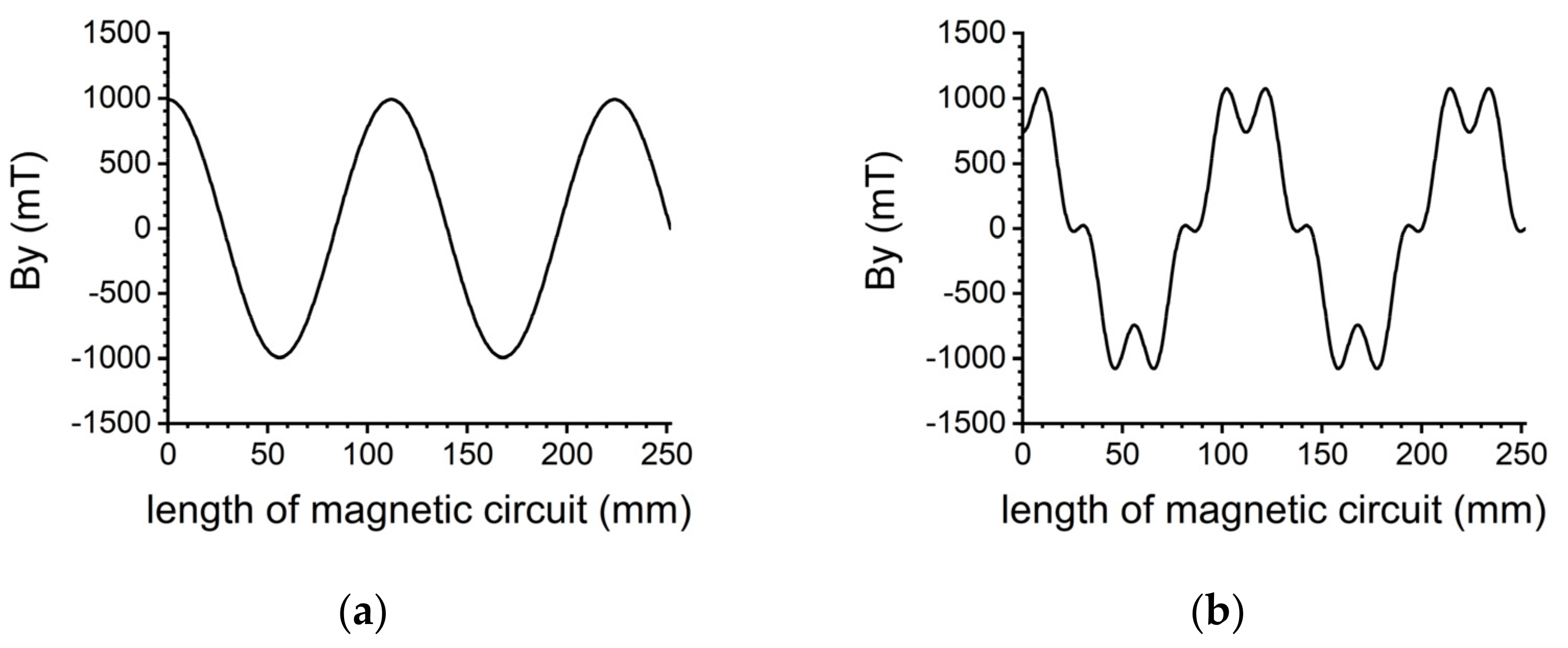
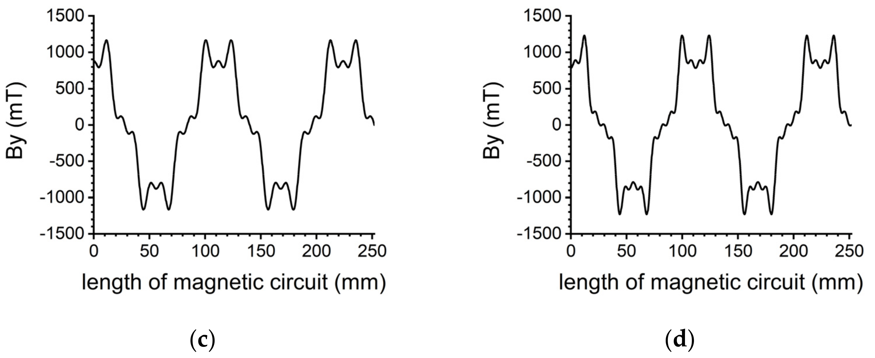
2.2. Calculation of Magnetic Flux Density

To ensure the safety of the wall-climbing robot working on the wall, the magnetic field intensity and magnetic flux density of the strong magnetic field should be calculated. The magnetic field intensity of the strong magnetic field can be obtained from Equations (13) and (21) as
H s = ( A ( n ) + B ( n ) ) ( e k ( n ) h 1 ) e k ( n ) y 2 × [ i · sin k ( n ) x + j · cos k ( n ) x ]
where i represents the component on the x-axis and j represents the component on the y-axis.
The magnetic flux density on the strong magnetic field side can be obtained from Equations (14) and (22). The magnetic flux density in the x-axis of the strong magnetic field is
B x ( n ) = - μ 0 ( A ( n ) + B ( n ) ) ( e k ( n ) h 1 ) e k ( n ) y 2 × sin k ( n ) x
The magnetic flux density in the y-axis of the strong magnetic side is
B y ( n ) = μ 0 ( A ( n ) + B ( n ) ) ( e k ( n ) h 1 ) e k ( n ) y 2 × cos k ( n ) x
From the analysis of Equations (23) and (24), given that
A ( n ) + B ( n ) = 4 M 0 n π sin n π 2 × [ sin n π l v 2 ( l m + l v ) + cos n π l v 2 ( l m + l v ) ]
let m be a non-negative integer; when n = 2 m , sin ( n π 2 ) = 0 , that is, regardless of whether l m and l v are equal or not, the magnetic flux density on the strong magnetic side does not contain 2 m harmonic components. If l m = l v , when n = ( 3 + 4 m ) , because
sin n π l v 2 ( l m + l v ) + cos n π l v 2 ( l m + l v ) = 0
at this time, the magnetic flux density on the strong magnetic side only contains ( 1 + 4 m ) subharmonic components.
The permanent magnetic adsorption device of the wall-climbing robot is composed of nine permanent magnets with the same size, their magnetization direction is perpendicular to one another, and the size of each permanent magnet in the x–y plane is l m = l v = h = 28 mm. When l m = l v = h = 28 mm and the total length of the permanent magnet is 252 mm, the magnetic flux density of the strong magnetic field of the Halbach array permanent magnetic adsorption device of the wall-climbing robot in the y-axis is solved in accordance with Equation (24). From the theoretical analysis, the magnetic flux density of the strong magnetic field in the y-axis is formed by the superposition of harmonics with different orders and only contains 1 + 4 m harmonics. Here, only the first four harmonics of the strong magnetic field at y = h are calculated. The curve of the magnetic flux density of the strong magnetic field with magnet length is obtained by superimposing them, as shown in Figure 3.
ANSYS software is used for numerical simulation of the Halbach array permanent magnet. The three-dimensional magnetic flux density distribution is shown in Figure 4a, and the magnetic flux density distribution of the strong magnetic side surface in the length direction of the permanent magnet is shown in Figure 4b.
The theoretically calculated magnetic flux density is compared to the result obtained by the ANSYS software, as shown in Figure 5. To facilitate the theoretical calculation, when establishing the coordinate system, the zero point of the x-axis is set at the middle position of the main magnet at the starting end. Hence, a phase lag of l m / 2 in the x-axis exists between the theoretical analysis and the finite element calculation, as shown in Figure 5a. Therefore, the phase of the theoretical calculation result in the x-axis should be moved forward, as shown in Figure 5b. The end effect of the magnet is not considered in the theoretical analysis, such that the results of the theoretical analysis and finite element calculation are relatively different at the two ends of the magnet. In addition, because the higher harmonics above the thirteenth order are not considered in the theoretical analysis, the lower harmonic order will also lead to the difference between the theoretical analysis results and the finite element results.
In accordance with the above analysis process, when the volume of the permanent magnet in the magnetic adsorption device is the same and the number of main magnets is divided into 2, 3, 4, 5, 6, 7, and 8, the magnetic flux density of the strong magnetic field magnet surface in the y-axis is calculated, as shown in Figure 6. Since Figure 5 has already analyzed the distribution of magnetic flux density on the surface of the strong magnetic field of the Halbach array magnetic circuit when the number of main magnets is 5, Figure 6 only includes the distribution of magnetic flux density on the surface of the strong magnetic field of the Halbach array magnetic circuit when the number of main magnets is 2, 3, 4, 6, 7, and 8.
Figure 6 compares the theoretical calculation results of the magnetic flux density of various Halbach array magnetic circuits with the finite element analysis results. With the increase in the number of main magnets, the coincidence degree of the two results is higher. The reason is that with the increase in the number of main magnets, the width of a single main magnet in the x-axis and the end effect region of a permanent magnet becomes smaller. Similar to Figure 5, since only a limited number of harmonic orders are considered, a low harmonic order still leads to a discrepancy between the theoretical analysis results and the finite element results.

3. Magnetic Force Calculation of Adsorption Device

3.1. Equivalent Magnetic Flux Density

In accordance with the calculation method of magnetic flux density and the calculation equation of magnetic adsorption force, the adsorption force generated by the permanent magnetic adsorption device when the wall-climbing robot works can be obtained. When using finite element software to calculate the magnetic adsorption force accurately, the magnetic field intensity acting on the surface of the steel plate should be calculated first. The B-H curve of the steel plate should then be interpolated to obtain the magnetic flux density acting on the plate surface. Owing to the heavy workload of interpolation calculation, interpolation calculation is extremely difficult to use in theoretical analysis. To simplify the work of theoretical calculation, in accordance with the concentrated magnetic phenomenon of ferromagnetic materials in the magnetic field, the magnetic flux density without steel plate at the corresponding space position is equivalent to the magnetic flux density acting on the working surface of the steel plate by setting the magnetic concentration coefficient λ , which is mainly related to the material. Here, we set the magnetic concentration coefficient of carbon steel to be 2. Figure 7 shows the magnetic flux density on the surface of the steel plate calculated using the finite element method at the corresponding position in the magnetic field space, the magnetic flux density at the corresponding position without the steel plate obtained using the theoretical method, and the equivalent magnetic flux density.
The analysis of Figure 7 indicates that in the middle section of the permanent magnet of the Halbach array magnetic circuit, the magnetic flux density, after equivalent magnetic flux density, is close to the result solved using the finite element method. A considerable difference exists at both ends of the permanent magnet. The main reason for the large difference between the results at the two ends is that the magnetization function does not form a good periodicity when only two main magnets exist in the Halbach array magnetic circuit and the end effect of the main magnets. To reduce the error caused by the end effect of the main magnet when the equivalent magnetic flux density is used to solve the magnetic adsorption force, a point is taken from the middle of each main magnet at both ends of the equivalent magnetic flux density curve. The actual magnetic flux density curve at both ends of the magnetic circuit is replaced with a line connecting the zero magnetic flux density at both ends, as shown in Figure 8.
Figure 8 demonstrates that after the two ends of the equivalent magnetic flux density are simplified in consideration of the end effect of the permanent magnet, the result is closer to the result calculated using the finite element software. To verify the accuracy of the above method, when the number of main magnets is 3, 4, 5, 6, 7, and 8, the equivalent magnetic flux density in consideration of the end effect of a permanent magnet is compared to the result calculated using the finite element software, as shown in Figure 9.
Figure 9 presents that with the increase in the number of main magnets, the periodicity of the Halbach array magnetic circuit is more evident. The coincidence degree between the equivalent magnetic flux density in consideration of the end effect and the result calculated using the finite element method is also higher.

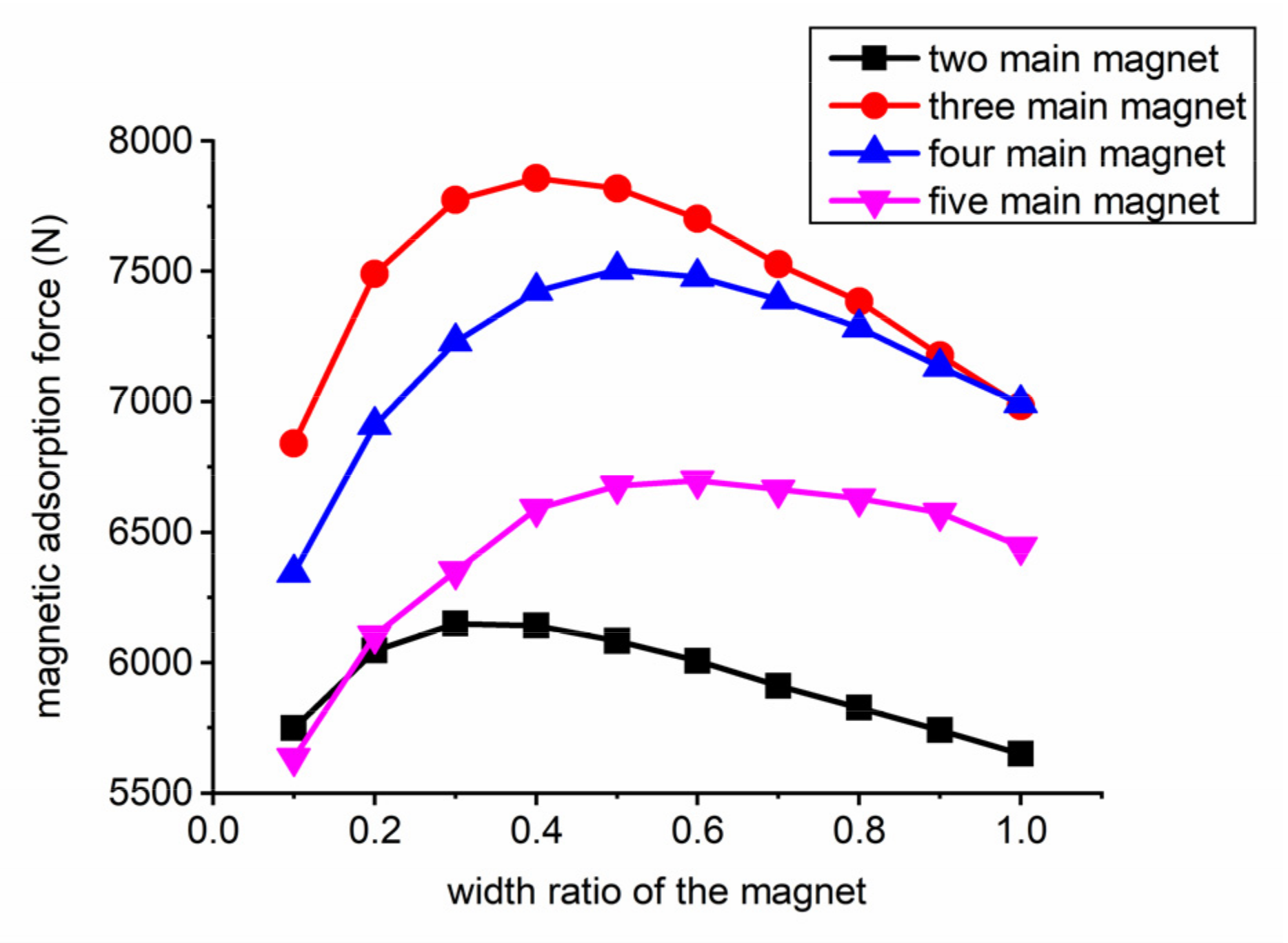
3.2. Calculation of Magnetic Adsorption Force

According to Equation (27), i.e., the calculation formula of magnetic adsorption force [26], the relationship between the magnetic adsorption force generated by the Halbach array permanent magnetic adsorption device of the wall-climbing robot, and the number of main magnets during the working magnetic gap can be determined, as shown in Figure 10.
F = n = 1 B i 2 S cos α 2 μ 0
where F is the magnetic adsorption force generated by the permanent magnetic adsorption device, B i is the magnetic flux density in the magnetic field, S is the effective adsorption area, α is the angle between the magnetic flux density and the vertical direction of the working surface, and μ 0 is the vacuum permeability.
Figure 10 illustrates that after the size of the permanent magnetic adsorption device is determined, the magnetic adsorption force shows a changing trend of first increasing and then decreasing by changing the number of main magnets.
In consideration of the deviation between the theoretical analysis results and the actual results, ANSYS software is used to analyze the permanent magnetic adsorption device when the number of main magnets is 2, 3, 4, and 5 and the width ratio of the vice magnet to the main magnet in the x-axis is changed. The aim is to calculate the magnetic adsorption force generated by the permanent magnetic adsorption device of the wall-climbing robot accurately. The analysis is in accordance with the variation trend of magnetic adsorption force and the number of main magnets in the theoretical analysis. The results are shown in Figure 11.
From Figure 11, when the width in the x-axis of the vice magnet is equal to that of the main magnet, the magnetic adsorption force is minimum for two main magnets, approximately equal for three and four main magnets, and small for five main magnets. The variation trend of the magnetic adsorption force and the number of main magnets of the permanent magnetic adsorption device calculated using the finite element software is consistent with the theoretical analysis. When the number of main magnets is determined, the magnetic adsorption force first increases and then decreases by changing the width ratio of the vice magnet to the main magnet in the x-axis. Following the magnetic adsorption force of the Halbach array permanent magnetic adsorption device of the wall-climbing robot calculated using the finite element software, when three main magnets exist, the magnetic adsorption force is the largest when the width ratio of the vice magnet to the main magnet in the x-axis is 0.4.
The analysis results of the Halbach array magnetic circuit indicate that the Halbach array permanent magnetic adsorption device of the wall-climbing robot is improved. The improved device is shown in Figure 12.

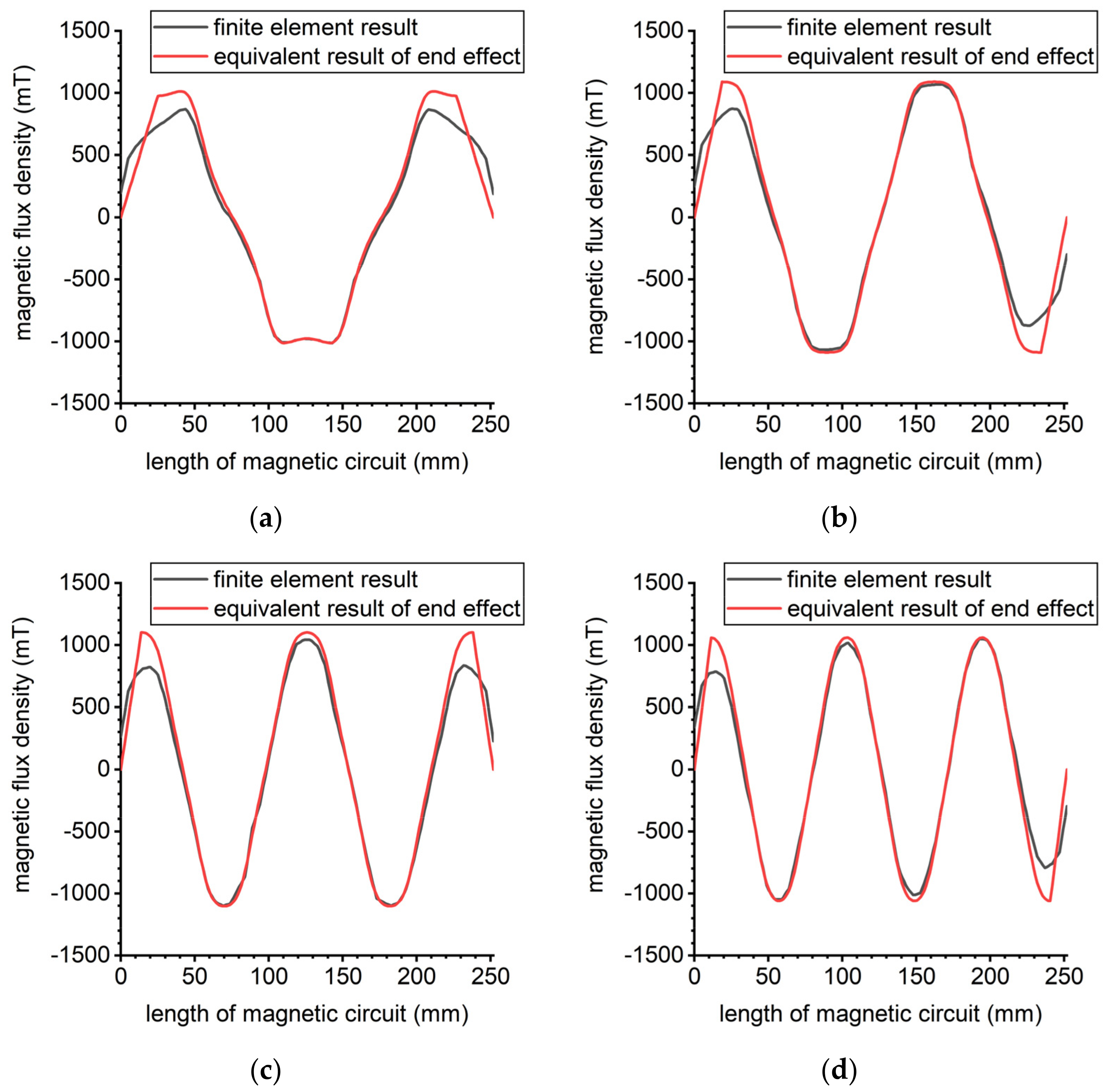
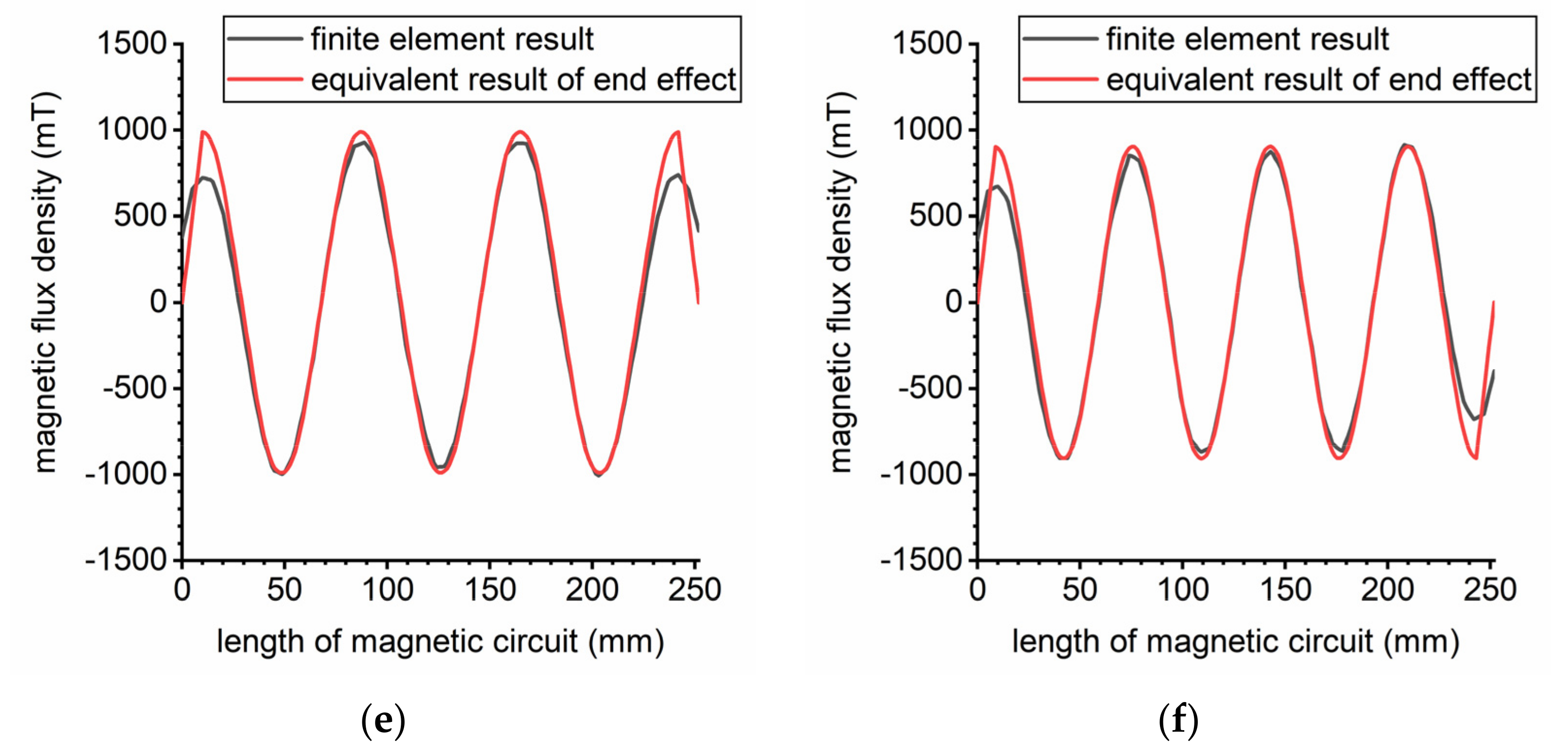
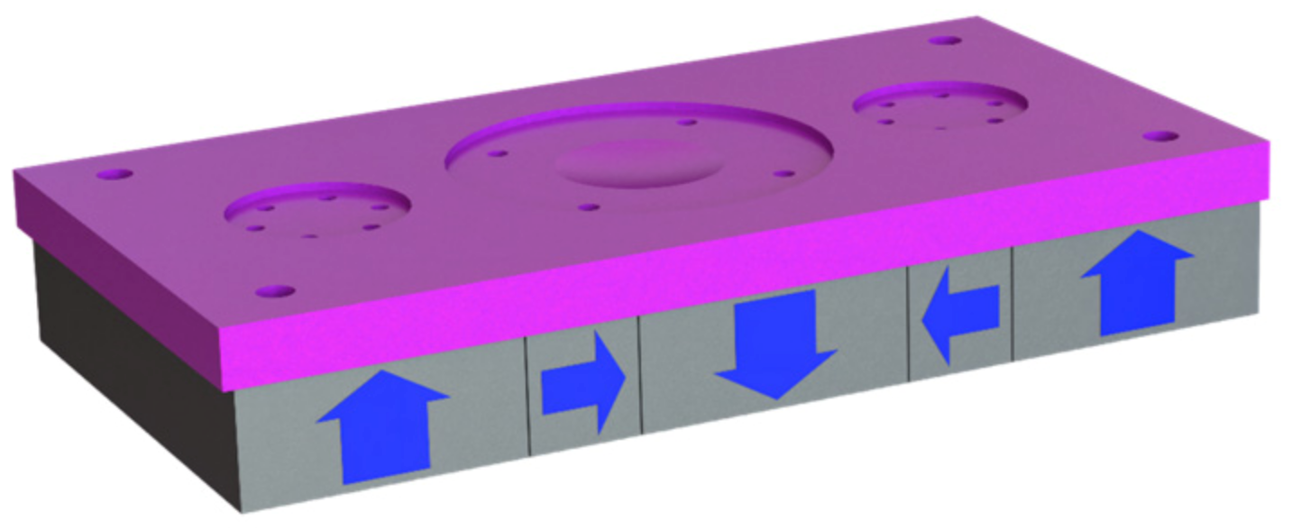
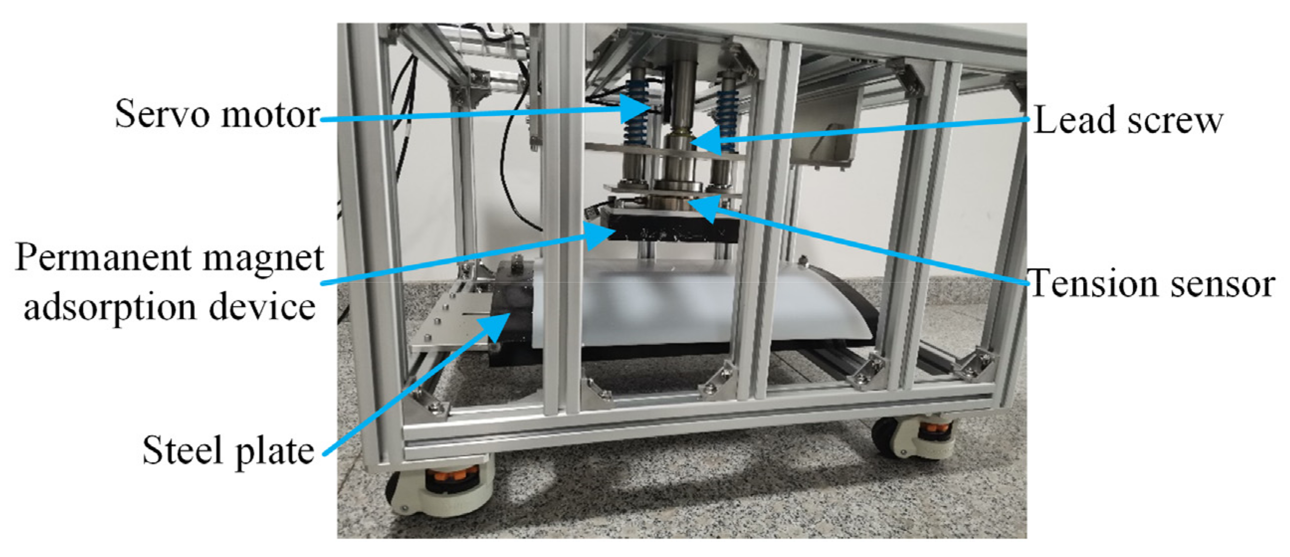
4. Experimental Verification

To ensure the safe operation of the wall-climbing robot on the wall and verify the accuracy of the above theoretical method, the magnetic adsorption force generated by the Halbach array permanent magnetic adsorption device of the wall-climbing robot should be measured. In the experiment, the magnetic adsorption force generated by the Halbach array permanent magnetic adsorption device of the wall-climbing robot before the improvement (the number of the main magnets is 5, and the width ratio of the vice magnet to the main magnet is 1) and after the improvement (the number of the main magnets is 3, and the width ratio of the vice magnet to the main magnet is 0.4) is measured with the change in the magnetic gap. The measured magnetic gap range is 5–35 mm, a sampling point is determined every 1 mm near the working magnetic gap of 10 mm, a sampling point is determined every 2 mm in other magnetic gap ranges, each sampling point is measured 5 times, and the average value is regarded as the magnetic adsorption force generated by the permanent magnetic adsorption device in the magnetic gap. The experimental platform is shown in Figure 13. The steel plate used to simulate the working wall is fixed at the bottom of the experimental platform. The experimental platform uses the servo motor to drive the lead screw to rotate to achieve precise adjustment of the distance between the permanent magnetic adsorption device and the steel plate. At the same time, a tension sensor is installed between the permanent magnetic adsorption device and the lead screw nut to measure the magnetic adsorption force generated by the permanent magnetic adsorption device. Figure 14 illustrates the experiment of the wall-climbing robot moving on the wall. The magnetic adsorption force generated by the Halbach array permanent magnetic adsorption device can ensure the reliable adsorption and safe operation of the wall-climbing robot on the wall.
The experimental results of magnetic adsorption force and magnetic gap are shown in Figure 15. At the working magnetic gap of 10 mm, the finite element calculation result of the magnetic adsorption force generated by the Halbach array permanent magnetic adsorption device of the wall-climbing robot before improvement is 6446 N, and the experimental measurement result is 5734 N. The magnetic adsorption force generated by the improved permanent magnetic adsorption device is 7857 N via finite element calculation and 7146 N via experimental measurement. The experimental results show that when the same volume of a permanent magnet is used in the Halbach array permanent magnetic adsorption device of the wall-climbing robot, the magnetic adsorption force generated by the improved permanent magnetic adsorption device is increased by 24.63% compared to before the improvement.

5. Discussion

Based on the Halbach array magnetic circuit analysis of ideal magnetization direction by Professor Mallinson [12], we analyze the Halbach array magnetic circuit with multiple perpendicular magnetization directions, which improves the relevant theory of the Halbach array magnetic circuit analysis. It is simpler to use “equivalent magnetic flux density” to analyze the magnetic adsorption force generated by the permanent magnet adsorption device than to use the quadruple integral to calculate the magnetic adsorption force [20]. By improving the Halbach array permanent magnet adsorption device, the magnetic adsorption force can be increased by about 14.74% compared to the permanent magnet adsorption device with the opposite magnetization direction under the condition of using the same permanent magnet [11].
In this paper, the magnetic adsorption force produced by the different Halbach array magnetic circuits is calculated by analyzing the magnetic flux density distribution of the Halbach array magnetic circuit and combining with the calculation equation of magnetic adsorption force. According to the analysis results, the permanent magnet adsorption de-vice of the wall-climbing robot is improved, and the utilization rate of magnets in the permanent magnet adsorption device is improved. Finally, the lightweight design of the permanent magnet adsorption device of the wall-climbing robot is realized. Wall-climbing robots and permanent magnet devices can be widely used in smart industries, ubiquitous environments, Industry 4.0 and medical devices, etc. [27,28]. We believe that the achievements of this work also have potential application value in other interdisciplinary fields.

6. Conclusions

In this paper, a method to calculate magnetic adsorption force by using the equivalent magnetic flux density is proposed for the Halbach array permanent magnetic adsorption device of a wall-climbing robot. The magnetic adsorption force generated by the permanent magnetic adsorption device of the wall-climbing robot composed of different Halbach array magnetic circuits is calculated using this method, and the accuracy of the method is verified by comparing its result with the finite element analysis results. In accordance with the calculation results, the permanent magnetic adsorption device of the wall-climbing robot is improved. The experimental results also show that the magnetic adsorption force generated by the improved permanent magnetic adsorption device is increased by 24.63% compared to before the improvement in the working magnetic gap.

Author Contributions

Conceptualization, M.Z.; Formal analysis, S.J. and J.J.; Resources, X.Z. (Xuan Zhang); Funding acquisition, X.Z. (Xiaojun Zhang); Writing—original draft, S.J. and X.Z. (Xiaojun Zhang); Writing—review and editing, M.Z. and X.Z. (Xuan Zhang). All authors have read and agreed to the published version of the manuscript.

Funding

This research was funded by National Key Research and Development Program (2018YFB1309401), Special Project for Civil-Military Integration Development in Hebei Province.

Institutional Review Board Statement

Not applicable.

Informed Consent Statement

Not applicable.

Data Availability Statement

The data presented in this study are available in the article.

Conflicts of Interest

The authors declare no conflict of interest.

References

  1. Song, C.; Cui, W. Review of Underwater Ship Hull Cleaning Technologies. J. Mar. Sci. Appl. 2020, 19, 415–429. [Google Scholar] [CrossRef]
  2. Wang, S. Research status and future development of wall-climbing robot. In Proceedings of the 2021 International Conference on Electronics, Circuits and Information Engineering (ECIE), Zhengzhou, China, 22–24 January 2021; pp. 122–130. [Google Scholar] [CrossRef]
  3. Schmidt, D.; Berns, K. Climbing robots for maintenance and inspections of vertical structures—A survey of design aspects and technologies. Rob. Auton. Syst. 2013, 61, 1288–1305. [Google Scholar] [CrossRef]
  4. Liang, P.; Gao, X.; Zhang, Q.; Gao, R.; Li, M.; Xu, Y.; Zhu, W. Design and stability analysis of a wall-climbing robot using propulsive force of propeller. Symmetry 2021, 13, 37. [Google Scholar] [CrossRef]
  5. Kindl, V.; Hruska, K.; Pechanek, R.; Skala, B. Redesign of an Undercarriage Wheel for a Self-Acting Robot. IEEE Trans. Magn. 2016, 52, 1–5. [Google Scholar] [CrossRef]
  6. Huang, H.; Li, D.; Xue, Z.; Chen, X.L.; Liu, S.; Leng, J.; Wei, Y. Design and performance analysis of a tracked wall-climbing robot for ship inspection in shipbuilding. Ocean Eng. 2017, 131, 224–230. [Google Scholar] [CrossRef]
  7. Hu, J.; Han, X.; Tao, Y.; Feng, S. A magnetic crawler wall-climbing robot with capacity of high payload on the convex surface. Rob. Auton. Syst. 2021, 148, 103907. [Google Scholar] [CrossRef]
  8. Gao, S.; Hou, R.; Li, J.; Pan, Y.; He, S.; Li, H. Magnetic Field Analysis and Structure Design of a New Magnetic Wheel for Wall-Climbing Robot. J. Supercond. Nov. Magn. 2021, 35, 529–537. [Google Scholar] [CrossRef]
  9. Zhao, Z.; Tao, Y.; Wang, J.; Hu, J. The multi-objective optimization design for the magnetic adsorption unit of wall-climbing robot. J. Mech. Sci. Technol. 2022, 36, 305–316. [Google Scholar] [CrossRef]
  10. Wu, M.; Pan, G.; Zhang, T.; Chen, S.; Zhuang, F.; Yan-Zheng, Z. Design and optimal research of a non-contact adjustable magnetic adhesion mechanism for a wall-climbing welding robot. Int. J. Adv. Robot. Syst. 2013, 10, 63. [Google Scholar] [CrossRef] [Green Version]
  11. Wu, M.; Gao, X.; Fu, Z.; Zhao, Y.; Chen, S. The mechanism design of a wheeled climbing welding robot with passing obstacles capability. Lect. Notes Electr. Eng. 2011, 88, 401–409. [Google Scholar] [CrossRef]
  12. Mallinson, J.C. One-Sided Fluxes—A Magnetic Curiosity? IEEE Trans. Magn. 1973, 9, 678–682. [Google Scholar] [CrossRef] [Green Version]
  13. Halbach, K. Strong rare earth cobalt quadrupoles. IEEE Trans. Nucl. Sci. 1979, 26, 3882–3884. [Google Scholar] [CrossRef]
  14. Yu, J.; Deng, Z.; Li, H.; Ma, S.; Zhao, J.; Wang, L. Vibration Suppression of High-Temperature Superconducting Maglev System via Electromagnetic Shunt Damper. J. Supercond. Nov. Magn. 2019, 32, 2819–2828. [Google Scholar] [CrossRef]
  15. Luo, C.; Zhang, K.; Duan, J.; Jing, Y. Study of Permanent Magnet Electrodynamic Suspension System with a Novel Halbach Array. J. Electr. Eng. Technol. 2020, 15, 969–977. [Google Scholar] [CrossRef]
  16. Golovanov, D.; Gerada, C. An Analytical Subdomain Model for Dual-Rotor Permanent Magnet Motor with Halbach Array. IEEE Trans. Magn. 2019, 55, 1–16. [Google Scholar] [CrossRef]
  17. Jing, L.; Pan, Y.; Wang, T.; Qu, R.; Cheng, P.T. Transient Analysis and Verification of a Magnetic Gear Integrated Permanent Magnet Brushless Machine with Halbach Arrays. IEEE J. Emerg. Sel. Top. Power Electron. 2021, 6777, 1–10. [Google Scholar] [CrossRef]
  18. Hoburg, J.F. Modeling Maglev Passenger Compartment Static Magnetic Fields From Linear Halbach Permanent-Magnet Arrays. IEEE Trans. Magn. 2004, 40, 59–64. [Google Scholar] [CrossRef]
  19. Meessen, K.J.; Gysen, B.L.J.; Paulides, J.J.H.; Lomonova, E.A. Three-dimensional magnetic field modeling of a cylindrical halbach array. IEEE Trans. Magn. 2010, 46, 1733–1736. [Google Scholar] [CrossRef]
  20. Qu, C.; Chen, Y.; Zhen, P.; Li, X. A Study on Magnetic Force Characteristics Between Two Cuboidal Permanent Magnets. J. Supercond. Nov. Magn. 2021, 34, 2441–2454. [Google Scholar] [CrossRef]
  21. Huang, R.; Liu, C.; Song, Z.; Zhao, H. Design and analysis of a novel axial-radial flux permanent magnet machine with Halbach-Array permanent magnets. Energies 2021, 14, 3639. [Google Scholar] [CrossRef]
  22. Wei, L.; Nakamura, T. A Novel Dual-Stator Hybrid Excited Permanent Magnet Vernier Machine with Halbach-Array PMs. IEEE Trans. Magn. 2021, 57, 1–5. [Google Scholar] [CrossRef]
  23. Tumanski, S. Handbook of Magnetic Measurements; CRC Press: Boca Raton, FL, USA, 2016; pp. 47–79. [Google Scholar]
  24. Prashanth, N.A. Flux maximization in wind turbine permanent magnet synchronous generator made of NdFeB permanent magnets. Mater. Today Proc. 2021, 49, 731–737. [Google Scholar] [CrossRef]
  25. Zhang, H.; Shen, Y.; Han, Y. Electromagnetic Fields and Waves, 2nd ed.; Tsinghua University Press: Beijing, China, 2016; pp. 87–90. [Google Scholar]
  26. Furlani, E.P. Permanent Magnet and Electromechanical Devices: Materials, Analysis, and Applications; Academic Press: New York, NY, USA, 2001; pp. 107–116. [Google Scholar]
  27. Thakur, N.; Han, C.Y. An ambient intelligence-based human behavior monitoring framework for ubiquitous environments. Information 2021, 12, 81. [Google Scholar] [CrossRef]
  28. Dziob, D.; Ramian, J.; Ramian, J.; Lisowski, B.; Laska, J. Design and construction of a chamber enabling the observation of living cells in the field of a constant magnetic force. Cells 2021, 10, 3339. [Google Scholar] [CrossRef]
Figure 1. (a) Axial motion posture of the wall-climbing robot; (b) Wall-climbing robot circular motion attitudes; (c) Wall-climbing robot permanent magnetic adsorption device.
Symmetry 14 00429 g001
Figure 2. (a) Three-dimensional coordinate system of the Halbach array; (b) Magnetization intensity function of the main magnet; (c) Magnetization intensity function of the vice magnet.
Symmetry 14 00429 g002aSymmetry 14 00429 g002b
Figure 3. (a) Magnetic flux density when the base wave is included; (b) Magnetic flux density of the base wave and fifth harmonic; (c) Magnetic flux density of the base wave, fifth harmonic, and ninth harmonic; (d) Magnetic flux density of the base wave, fifth harmonic, ninth harmonic, and thirteenth harmonic.
Symmetry 14 00429 g003aSymmetry 14 00429 g003b
Figure 4. Magnetic flux density distribution of Halbach array permanent magnet: (a) magnetic flux density distribution on that three-dimensional surface of the permanent magnet; (b) magnetic flux density distribution on the surface of the strong magnetic side in the length direction of the permanent magnet.
Symmetry 14 00429 g004
Figure 5. (a) Results without phase correction; (b) Results after phase correction.
Symmetry 14 00429 g005
Figure 6. (a) When the number of main magnets is 2; (b) When the number of main magnets is 3; (c) When the number of main magnets is 4; (d) When the number of main magnets is 6; (e) When the number of main magnets is 7; (f) When the number of main magnets is 8.
Symmetry 14 00429 g006
Figure 7. Magnetic flux density calculated using different methods.
Symmetry 14 00429 g007
Figure 8. Equivalent magnetic flux density considering end effect.
Symmetry 14 00429 g008
Figure 9. (a) Equivalent magnetic flux density of three main magnets; (b) Equivalent magnetic flux density of four main magnets; (c) Equivalent magnetic flux density of five main magnets; (d) Equivalent magnetic flux density of six main magnets; (e) Equivalent magnetic flux density of seven main magnets; (f) Equivalent magnetic flux density of eight main magnets.
Symmetry 14 00429 g009aSymmetry 14 00429 g009b
Figure 10. Magnetic adsorption force with different numbers of main magnets.
Symmetry 14 00429 g010
Figure 11. Relationship between adsorption force and the number of main magnets and the width of vice/main magnets.
Symmetry 14 00429 g011
Figure 12. Improved permanent magnetic adsorption device.
Symmetry 14 00429 g012
Figure 13. Magnetic adsorption force measurement experiment.
Symmetry 14 00429 g013
Figure 14. Wall motion experiment of the wall-climbing robot.
Symmetry 14 00429 g014
Figure 15. Experimental results of magnetic adsorption force.
Symmetry 14 00429 g015
Publisher’s Note: MDPI stays neutral with regard to jurisdictional claims in published maps and institutional affiliations.

