Abstract
The step-up power electronic converter, which is easily implemented with two symmetric parallel-boost stages, has recently been proposed in the literature, showing considerable voltage gains with no excessive duty cycle, thus minimizing heat and other adverse effects. Its other advantages are floating-output voltage and increased power density because of the diminution of the capacitors’ voltage rating. In this paper, the Lyapunov-based robust stability of a converter operating in both closed- and open-loop is proved, showing its versatility even during the variation of parameters, which nullifies the symmetry of the converter. Simulation and experimental data allow the corroboration of the analysis.
1. Introduction
In the transition from traditional power systems to smart grids, symmetry is a term connected with power system modeling and analysis. Modern electronics widely use electronic converters, allowing impedance coupling in electric source and load connections. Frequently, symmetry in the electronic design enhances singular characteristics for the benefit of an improved operation. For instance, voltage step-up or boost converters are commonly used in the generation of green energy from various homogeneous power harvesting sources to match the voltage levels of loads such as batteries, supercapacitors, grids, and smart grids, among many others [1]. Increasing the power-per-size relationship (power density) and lowering the building cost are also relevant characteristics of these step-up converters. State-of-the-art symmetric circuit configurations (topologies) provide these characteristics, as well as bi-directionality and high voltage gain [2,3,4].
Still, there is a need to enhance the power density of electronic converters and, for instance, increase the voltage gain of boost-type converters, which is a trade-off between size and voltage amplification. A classic boost converter with a single capacitor gains up to five times the input voltage with moderate efficiency. Still, the output capacitor must be at least of such an output voltage rating [5] and, hence, of a relatively big size, and other series or cascaded configurations have this drawback. On the other hand, gains that are more significant than five can be obtained with different topologies at the cost of an increased component number, including those with magnetic coupling [6,7,8].
The topology studied in this paper and shown in Figure 1 effectively reduces the volume and cost of having a (big) single-output capacitor (see, for example, [9,10,11]); this is achieved by lowering the voltage rating because of a symmetric connection of two capacitors. Although other double-series unidirectional capacitor topologies were presented in [12], the configuration used in this paper requires only two switches, can be expanded for bidirectional usage (adding two more switches), and provides significant voltage gain from moderate duty cycles, thus reducing conduction losses. Related topologies and their characteristics were also presented in a review [13] and in the literary works of [14,15,16,17]; however, none of the above include the dynamic analysis of the topology used in this paper, and, nowadays, knowing power converters’ properties—such as their controllability and stability in closed- and open-loop conditions—is indispensable.
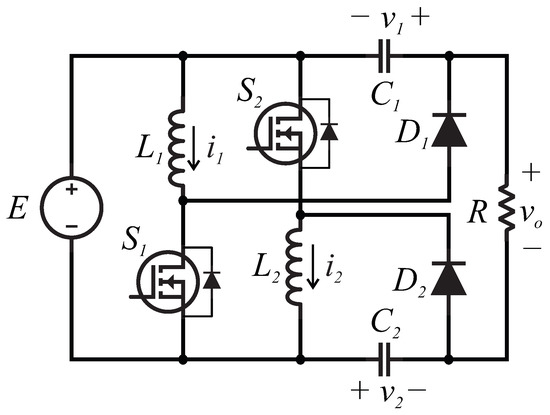
Figure 1.
Dual-capacitor boost converter topology used in this paper.
To the author’s knowledge, the presented topology is novel and has not been studied for its dynamic and control behavior. Hence, the contributions of this paper to the state of the art are the following:
- A novel symmetric dual-capacitor boost converter topology.
- The (polytopic) model of the topology in which dynamic and linear parameters are varied, in addition to numerical and experimental validations.
- An asymptotic stability analysis against bounded parameter uncertainty in both closed and open loops, including asymmetric and symmetric stances.
- Numerical and experimental corroboration of stability and performance using a PI control scheme.
2. Preliminaries
From the topology shown in Figure 1, equal PWM pulses in both switches allow the energy charge in both inductors and the discharge in both capacitors, respectively, whose voltages and increase, which also augments the output voltage in the load R by:
If the duty cycle d of the PWM remains zero, the output voltage will be , as in a regular one-stage boost converter. Duty-cycle values near unity are avoided because of the high switch conduction losses, which induce overheating and possible device damage. Note that the voltage rating of is less than that of a regular single-capacitor boost converter (in a boost converter, the voltage of the output capacitor must be at least ), and that serialized stages allow more considerable voltage gains.
A standard average technique in a CCM (see [5], for instance) allows one to obtain the expressions that model the converter:
In addition, a simple analysis for smart ripple consideration allows one to obtain the ideal output voltage gain:
In Figure 2 is shown a simple validation of the above model in which is used to obtain V. The adequate values for obtaining a CCM with a 100 W load are calculated (Table 1). A 3% error in the steady state and a maximum of 9% error in the transient stage due to some non-ideal characteristics were included in the simulation software as the forward diode voltage and diode resistance of the switches. Nonetheless, the above model is qualitatively accurate and tractable for control purposes.
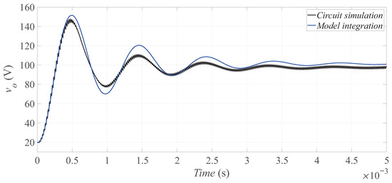
Figure 2.
Comparative data obtained from the integration and simulation of the mathematical model; the circuit was implemented in the PSIM software with some non-ideal characteristics that could not be omitted, such as some of the MOSFETs’ diodes. The maximum error in the steady state is 3%, and in the transient stage, it is approximately 9%; the duty cycle is , and the parameters of the circuit are shown in Table 1.

Table 1.
Parameters for the converter.
3. Results
The state-space representation of (5) can be written as:
where
and the time dependence of A (recall that ) and the states is omitted for readability. Since A is invertible, the variable change allows for the shifting of the operating point to the origin; hence:
An LPV representation of the above model is:
where are numbers such that , (simplex), and ; that is, the matrix A is represented as a polytopic sum of the vertexes multiplied by the corresponding variation . Recall that the vertexes are built with the combinations of the maximum and minimum values of each nonzero entry of A, since one considers that all of the converter parameters are time-varying within bounded values; for instance, one knows that and ; hence, the first row of the third column of has the lowest possible value . Repeating that for the rest of entries results in:
which represents the first vertex of the polytopic representation. For the second vertex, the first row of the third column of is the greatest possible value , while the rest of the entries remain with their minimum values (underlined). For the third vertex, the second row of the fourth column of is built by finding the minimum () and maximum () values of the entry, and the rest of the entries remain in their minimal values. Once vertexes with a single maximum entry are found (eight), those with combinations of two or more overlined entries are found to obtain the 64 vertexes. That is, the rest of the vertexes are built with a binary combination of the minimum and maximum entries of A:
where all . The vertexes are constant in the above polytopic representation, and the values represent the variations in the parameter. The advantage of such a representation is that the robust control theory demonstrates global asymptotic stability if all of the vertexes are individually Lyapunov-stable using a common Lyapunov function.
Theorem 1.
Proof.
Consider the common Lyapunov candidate function
where all values of eta are positive constants; hence, and is positive for any other argument values. The time derivative along the system trajectories for some vertex of (10) is:
Since all state variables are positive (the configuration of diodes only allows positive values), the only conditions for negativeness of are:
As all parameters are considered to be time-varying but bounded within known positive limits, one can always find constants and such that . By the theory of robust control [18], all of the conditions for global stability are met. □
4. Numerical Simulation
Consider the nominal parameters of Table 1, a classic PI voltage controller set to a 100 V reference with variation ranges of H, H, F, and F, and similar bounds for and . Figure 3 shows the behavior of the output voltage for representative parameter variations; the different combinations of other parameters do not affect the dynamics considerably with respect to the nominal values and are not shown in such a plot. However, the most important characteristic is the asymptotic stability in the closed loop.
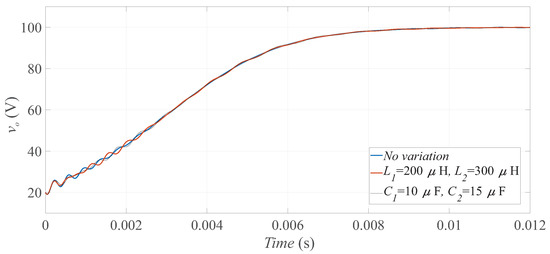
Figure 3.
Comparison of the converter operating in a closed loop with a classic PI controller and different parameter-varying scenarios.
5. Experimental Results
A converter prototype was built to corroborate the analytic and numerical results (Figure 4). The first test was performed with an abrupt load change from 100 to 50 with a 600 W programmable DC electronic load (Model 8510 from BK PRECISION). This is shown at s of Figure 5. The experimental data were captured with a four-channel oscilloscope and plotted in Matlab; hence, the time shown is used only for reference.
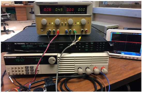
Figure 4.
Experimental test platform.
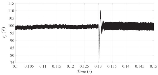
Figure 5.
Output voltage during an abrupt load change to half of the nominal value. The converter showed acceptable dynamic behavior.
The second test consisted of the modification of the values H and F with the expectation of preserving the stability for a reference change from 20 to 100 V. Figure 6 shows the output voltage behavior; it can be easily noted that the stability was preserved even for such parametric changes. Figure 7 shows that these parametric changes only affected the ripple in a capacitor, but the dynamic behavior remained acceptable.
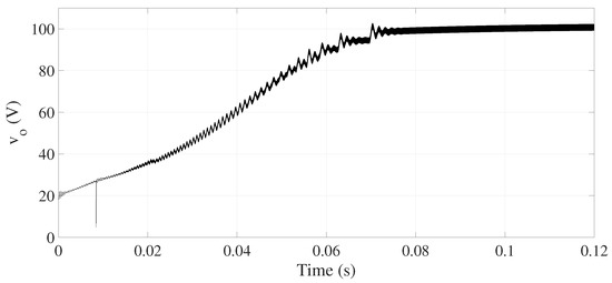
Figure 6.
Output voltage during an abrupt reference change and with asymmetric parameters. The converter showed acceptable dynamic behavior.
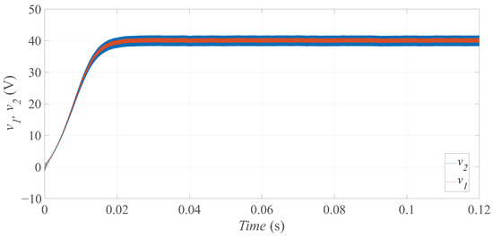
Figure 7.
Capacitors’ voltages during an abrupt reference change and with asymmetric parameters. The converter showed acceptable dynamic behavior.
6. Conclusions
This paper reports a study of robust stability against parametrically bounded and arbitrary variations for a double-capacitor boost converter. This topology showed excellent stability properties, and the tuning of a simple controller was easy to perform without a destabilization risk. Additionally, the significant voltage gain, high power density, high efficiency (about 95% for the proposed parameters), and the non-pulsating voltage between the input and output made the converter versatile. An analysis of parasitic components in electronic devices for high-resilience systems will be performed in future work. In addition, cascaded configurations and the dynamic behavior with a constant power load must be further analyzed.
Funding
This research received no external funding.
Data Availability Statement
Not applicable.
Conflicts of Interest
The author declares no conflict of interest.
Abbreviations
The following abbreviations are used in this manuscript:
| CCM | Continuous Conduction Mode |
| LPV | Linear Parameter Variation |
| PI | Proportional–Integral |
| PWM | Pulse-Width Modulation |
References
- Ouahada, K.; Longe, O.M. Smart Energy Management for Smart Grids; MDPI—Multidisciplinary Digital Publishing Institute: Basel, Switzerland, 2020. [Google Scholar]
- Mukhtar, N.M.; Lu, D.D.C. A bidirectional flyback converter with cross-coupled non-dissipative snubber circuits. In Proceedings of the 2017 IEEE International Telecommunications Energy Conference (INTELEC), Broadbeach, QLD, Australia, 22–26 October 2017; pp. 476–481. [Google Scholar]
- Zhang, H.; Chen, Y.; Park, S.J.; Kim, D.H. A Family of Bidirectional DC–DC Converters for Battery Storage System with High Voltage Gain. Energies 2019, 12, 1289. [Google Scholar] [CrossRef]
- Lin, X.; Wang, F.; Iu, H.H. A New Bridgeless High Step-up Voltage Gain PFC Converter with Reduced Conduction Losses and Low Voltage Stress. Energies 2018, 11, 2640. [Google Scholar] [CrossRef]
- Sira-Ramirez, H.J.; Silva-Ortigoza, R. Control Design Techniques in Power Electronics Devices; Springer Science & Business Media: Berlin/Heidelberg, Germany, 2006. [Google Scholar]
- Rosas-Caro, J.C.; Mancilla-David, F.; Mayo-Maldonado, J.C.; Gonzalez-Lopez, J.M.; Torres-Espinosa, H.L.; Valdez-Resendiz, J.E. A transformer-less high-gain boost converter with input current ripple cancelation at a selectable duty cycle. IEEE Trans. Ind. Electron. 2012, 60, 4492–4499. [Google Scholar] [CrossRef]
- Amir, A.; Che, H.S.; Amir, A.; El Khateb, A.; Abd Rahim, N. Transformerless high gain boost and buck-boost DC-DC converters based on extendable switched capacitor (SC) cell for stand-alone photovoltaic system. Sol. Energy 2018, 171, 212–222. [Google Scholar] [CrossRef]
- Yao, T.; Nan, C.; Ayyanar, R. A new soft-switching topology for switched inductor high gain boost. IEEE Trans. Ind. Appl. 2018, 54, 2449–2458. [Google Scholar] [CrossRef]
- Yang, L.S.; Liang, T.J.; Chen, J.F. Transformerless DC–DC converters with high step-up voltage gain. IEEE Trans. Ind. Electron. 2009, 56, 3144–3152. [Google Scholar] [CrossRef]
- Yang, L.S.; Liang, T.J. Analysis and implementation of a novel bidirectional DC–DC converter. IEEE Trans. Ind. Electron. 2011, 59, 422–434. [Google Scholar] [CrossRef]
- Liao, H.; Chen, Y.T.; Chen, L.; Chen, J.F. Development of a Bidirectional DC–DC Converter with Rapid Energy Bidirectional Transition Technology. Energies 2022, 15, 4583. [Google Scholar] [CrossRef]
- Suciu, V.M.; Salcu, S.I.; Pacuraru, A.M.; Pintilie, L.N.; Szekely, N.C.; Teodosescu, P.D. Independent Double-Boost Interleaved Converter with Three-Level Output. Appl. Sci. 2021, 11, 5993. [Google Scholar] [CrossRef]
- Ortiz-Castrillón, J.R.; Mejía-Ruíz, G.E.; Muñoz-Galeano, N.; López-Lezama, J.M.; Saldarriaga-Zuluaga, S.D. PFC Single-Phase AC/DC Boost Converters: Bridge, Semi-Bridgeless, and Bridgeless Topologies. Appl. Sci. 2021, 11, 7651. [Google Scholar] [CrossRef]
- Do, N.N.; Huang, B.S.; Nguyen, T.T.; Wu, J.H.; Liu, Y.C.; Chiu, H.J. An Efficiency-Optimized Totem-pole Bridgeless Power Factor Correction Regulator using GaN HEMTs. In Proceedings of the 2020 International Symposium on Computer, Consumer and Control (IS3C), Taichung City, Taiwan, 13–16 November 2020; pp. 351–355. [Google Scholar]
- López-Santos, O.; Aldana-Rodríguez, Y.A.; Garcia, G.; Martínez-Salamero, L. A unified multimode control of a DC–DC interlinking converter integrated into a hybrid microgrid. Electronics 2019, 8, 1314. [Google Scholar] [CrossRef]
- Sethuraman, S.S.; Santha, K.; Mihet-Popa, L.; Bharatiraja, C. A modified topology of a high efficiency bidirectional type DC–DC converter by synchronous rectification. Electronics 2020, 9, 1555. [Google Scholar] [CrossRef]
- Azad, F.S. Development of a Novel Single Phase Non-Isolated AC-DC Zeta Converter for Improved Power Quality. Ph.D. Thesis, Department of Electrical and Electronic Engineering, Islamic University of Technology, Dhaka, Bangladesh, 2021. [Google Scholar]
- Liu, K.Z.; Yao, Y. Robust Control: Theory and Applications; John Wiley & Sons: Hoboken, NJ, USA, 2016. [Google Scholar]
Publisher’s Note: MDPI stays neutral with regard to jurisdictional claims in published maps and institutional affiliations. |
© 2022 by the author. Licensee MDPI, Basel, Switzerland. This article is an open access article distributed under the terms and conditions of the Creative Commons Attribution (CC BY) license (https://creativecommons.org/licenses/by/4.0/).