Article

Memristive Structure-Based Chaotic System for PRNG

1
Department of Radioengineering and Information Security, Yuriy Fedkovych Chernivtsi National University, 58012 Chernivtsi, Ukraine
2
Faculty of Electrical Engineering and Computer Science, Stefan cel Mare University of Suceava, 720229 Suceava, Romania
3
Department of Electronics and Telecommunications, Politecnico di Torino, 10129 Torino, Italy
*
Author to whom correspondence should be addressed.
Symmetry 2022, 14(1), 68; https://doi.org/10.3390/sym14010068
Submission received: 1 December 2021 / Revised: 24 December 2021 / Accepted: 26 December 2021 / Published: 4 January 2022
(This article belongs to the Special Issue Chaotic Systems and Nonlinear Dynamics)

Abstract

:
This paper suggests an approach to generate pseudo-random sequences based on the discrete-time model of the simple memristive chaotic system. We show that implementing Euler’s and Runge–Kutta’s methods for the simulation solutions gives the possibility of obtaining chaotic sequences that maintain general properties of the original chaotic system. A preliminary criterion based on the binary sequence balance estimation is proposed and applied to separate any binary representation of the chaotic time sequences into random and non-random parts. This gives us the possibility to delete obviously non-random sequences prior to the post-processing. The investigations were performed for arithmetic with both fixed and floating points. In both cases, the obtained sequences successfully passed the NIST SP 800-22 statistical tests. The utilization of the unidirectional asymmetric coupling of chaotic systems without full synchronization between them was suggested to increase the performance of the chaotic pseudo-random number generator (CPRNG) and avoid identical sequences on different outputs of the coupled systems. The proposed CPRNG was also implemented and tested on FPGA using Euler’s method and fixed-point arithmetic for possible usage in different applications. The FPGA implementation of CPRNG supports a generation speed up to 1.2 Gbits/s for a clock frequency of 50 MHz. In addition, we presented an example of the application of CPRNG to symmetric image encryption, but nevertheless, one is suitable for the encryption of any binary source.

1. Introduction

A chaotic system generates signals that combine the properties of deterministic and random processes. Contrary to the deterministic nature, a chaotic system is a source of information that provides the average value of Shannon entropy over zero, which distinguishes it from periodic sources that characterize zero entropy. Chaotic signals are generated by determined nonlinear systems, but they are unpredictable at long time intervals and very sensitive to the initial conditions. The random character of signals generated by dynamical systems makes it possible to use these systems as a base for creating the generator of pseudo-random numbers (PRNG) for many applications in circuit theory and communication systems [1,2,3,4,5].
There are two types of chaotic systems: discrete and continuous. The first type is described by maps, and the second one is described by nonlinear differential equations. To obtain a digital realization of continuous chaotic systems, we applied one of the well-known ODE modeling methods to a mathematical model of the system. The modeling methods and precision of calculation should be chosen correctly to ensure the original dynamics of systems [4].
A Random Number Generator (RNG) is a basic element of cryptographic applications and is widely used to generate keys, keystreams for Vernam cipher, digital signatures, etc. There are two types of generators—truly random number generator (TRNG) and PRNG—which differ by the reproducibility of the previously generated sequence and its repeatability. To build an RNG, physical processes with unpredictable behavior are usually used, such as amplified thermal noise; the state of a deterministic system that is very sensitive to thermal noise; the timing of radioactive decay; or pauses between key switching.
The application of chaotic systems for an RNG has been proposed in many articles [6,7,8,9,10]. The classification, main structures, and a comparison of chaotic TRNGs can be found in [11]. In [8], the one-dimensional map was utilized to obtain a sequence that was previously digitized by a one-bit ADC influenced by noise and perturbation equal to half of the quantization step. This technique provides a random sequence generation speed over 10 Mbit/s, and the output sequence successfully passed the NIST tests. Nonlinear post-processing or feedback correction was used in [9] to increase the randomness of a TRNG. Integral implementation is also proposed and simulated in [10].
In contrast to TRNG, PRNG can be only implemented digitally. The pseudorandom sequence depends on the value of a secret key. The secret key can be used many times to reproduce the same sequence. PRNG has to ensure a sufficiently long repetition period and statistical characteristics close to TRNG according to the requirements for cryptographic security. Many papers have focused on the design of PRNGs in software or FPGA implementations for encryption [7,12,13,14,15,16,17,18].
The most known continuous-time chaotic systems do not describe real electric circuits but rather other physical processes, such as atmospheric phenomena [19], chemical reaction [20], and artificial mathematical constructions [21], modeled by Lorentz, Rösler and Sprott systems, respectively. The integral implementation of such systems is realizable but more complicated in comparison with the original electrical circuits; for example, Chua and Colpitts oscillators. It should be noted that for any dynamical system, nonlinearity is the main reason for chaotic behavior. The usage of new nonlinear elements allows the number of simple chaotic circles to be increased. An adequate element is the memristor, foreseen in 1971 by Chua as a result of searching the symmetry between fundamental elements [22] and then developed by HP [23]. The memristor is the fourth fundamental element of electrical circuits, next to the resistor, capacitor, and inductance. This is a resistor with memory that can form a major part of computing devices instead of transistors [24,25].
Currently, the properties of the memristor are being extensively investigated [26,27,28]. The analysis of the direct and alternating currents of the nonlinear dynamics of a tantalum oxide memristor is presented in [29,30].
Many periodic and chaotic oscillators based on memristors or memristive devices with different models of their nonlinear characteristics were proposed and studied in [31,32,33,34,35,36,37,38]. Besides the above-mentioned works, four fractional-order memristive chaotic systems have been proposed recently. These circuits provide a variety of dynamic states, such as the coexistence of hidden, chaotic, and hyperchaotic attractors, and other complex phenomena [39].
The development of algorithms for image encryption using chaotic dynamics is a key field of the current state-of-the-art research. One of the main challenges is a generalization of approaches to the realization of complex high-order chaotic systems or their combinations, algorithms of transformation of chaotic sequences in encryption keys, and increasing encryption efficiency [40,41,42].
In this paper, the utilization of an electrical oscillator model is offered based on a memristive device for creating PRNG [35]. This circuit consists of three elements—a capacitor, inductance, and nonideal memristor—which were implemented experimentally.
To obtain a pseudorandom sequence, we use a binary representation of chaotic numbers in the computing device memory. The bits balance is proposed and substantiated as a preliminary criterion to separate non-random (most significant) bits, which are discarded, and random (least significant) bits, which can be exposed for post-processing to conceal a generator state. In contradistinction to [14,15,17,40,43,44,45,46], the bit balance allows us to clearly distinguish and discard bits that cause a correlation between two sequential chaotic iterations, avoiding intuitive or empirical decisions.
One of the ways to improve the quality of CPRNG, namely the repetition period, is to increase the dimension of the basic chaotic system that is reached by coupling low-dimensional systems. The variety of coupling methods includes the ring, cross-section, and star structure, ultra-weakly coupled interaction, and others [47,48,49,50]. In this paper, we propose to use a unidirectional connection of systems to increase the number of output variables; thus, the performance of the CPRNG can be increased. In order to ensure that there is not complete synchronization between systems with arbitrary coupling strength, we propose to connect them via an asymmetric connection, such as the inertial or dissipative coupling of different circuit points, allowing us to optimize the productivity of CPRNG considering the available resources and making our method differ from others [47,49,50].
The organization of the paper is as follows. In Section 2, the model description and solution simulation are presented. Simulation results and the practical implementation of numerical methods by FPGA and NIST tests are given in Section 3. Coupling methods of low-dimensional chaotic systems to increase the output number and performance of PRNG are described in Section 4. The example of the application of CPRNG to image encryption is presented in Section 5. Finally, in Section 6 the main results are concluded.

2. Description of Mathematical Model and Solutions Simulation

2.1. Memristive Structure-Based Chaotic System

One of the simplest generators of chaotic oscillations based on a memristive structure was described and realized in [35]. The circuit consists of three series-connected elements: inductance, a capacitor, and a nonideal memristor (Figure 1). The used memristor model is a model of a generalized memristive device [51] whose characteristics do not correspond to characteristics of the ideal memristor introduced in [23]. The memristive structure is a non-linear active element that replaces the third reactive element that is needed to provide chaotic oscillations in a circuit.
The nonlinear characteristic of the memristive structure is described by the next equations:
V M = β ( z 2 1 ) i M d z d t = i M α z i M z
where V M is the voltage drop across the memristive structure, i M is the current through the memristive structure, z is the internal variable responsible for the memory effect, and α , β are the memristive structure parameters.
The circuit dynamic (Figure 1) is described by the following equations [35]:
d x d t = y C d y d t = 1 L [ x + β ( z 2 1 ) y ] d z d t = y α z + y z
where x , y , z are the state variables, and x = u C , y = i M , C = 1 F , L = 3 H , α = 0.6 , and β = 1.6 are the system parameters.
The positive value of the largest Lyapunov exponent indicates the chaotic behavior in the system. For the equations system (2), the corresponding diagram of Lyapunov exponents that is obtained by Benettin’s method is given in Figure 2.
The periodic λ 1 = 0 and chaotic λ 1 > 0 modes appear in the system for the values of β 1 , 1.7 .
Figure 2a indicates that when C = 1 F , L = 3 H , β = 1.52 , and α = 0.6 , the Lyapunov exponents are λ 1 = 0.0335 , λ 2 = 0.0008 , and λ 3 = 0.596 . The largest exponent is greater than zero, and the sum of exponents is negative λ 1 + λ 2 + λ 3 = 0.563 , which shows the chaotic behavior of the system [52].
The changing of other system parameters (L and C) for α = 0.6 (see Figure 2b,c) leads to the occurrence of different chaotic and periodic modes in the system (2) in a wide range of values of its parameters.

2.2. Solutions Simulation

The numerical simulation methods of differential equations differ according to their approximation degree of the exact system solutions. Among them, the most used methods are the Euler and the Runge–Kutta methods. Widely used methods of numerical simulation imply the transformation of the continuous system into a discrete map. Due to the sensitivity to arbitrarily small deviations of the initial conditions, the exact solutions of chaotic systems models cannot be obtained with any methods. Nevertheless, a discrete model can be used to study the original system when the outputs of both have the same statistical properties.
The essence of numerical methods is to present a system of differential equations in the form of a recurrent dependence and calculate sequence points on the trajectory in discrete moments with timestep Δ t .
The least computational complexity is achieved with Euler’s method, where the ratio between adjacent points of the system trajectories (2) is described by the following equations:
x n + 1 = f 1 ( t n , y n ) Δ t + x n y n + 1 = f 2 ( t n , x n , y n , z n ) Δ t + y n z n + 1 = f 3 ( t n , y n , z n ) Δ t + z n
where f 1 = y n C , f 2 = 1 L x n + β ( z n 2 1 ) y n , f 3 = y n α z n + y n z n .
The Runge–Kutta fourth-order method is characterized by a higher precision of calculations. According to this method, the ratio between the system states in successive time points is as follows:
x n + 1 = x n + 1 6 ( k 1 + 2 k 2 + 2 k 3 + k 4 ) Δ t y n + 1 = y n + 1 6 ( m 1 + 2 m 2 + 2 m 3 + m 4 ) Δ t z n + 1 = z n + 1 6 ( l 1 + 2 l 2 + 2 l 3 + l 4 ) Δ t
where k 1 = f 1 ( t n , y n ) ,   m 1 = f 2 ( t n , x n , y n , z n ) ,   l 1 = f 3 ( t n , y n , z n ) ,   k 2 = f 1 ( t n + Δ t 2 , y n + m 1 2 ) ,   m 2 = f 2 ( t n + Δ t 2 , x n + k 1 2 , y n + m 1 2 , z n + l 1 2 ) ,   l 2 = f 3 ( t n + Δ t 2 , y n + m 1 2 , z n + l 1 2 ) ,   k 3 = f 1 ( t n + Δ t 2 , y n + m 2 2 ) ,   m 3 = f 2 ( t n + Δ t 2 , x n + k 2 2 , y n + m 2 2 , z n + l 2 2 ) ,   l 3 = f 3 ( t n + Δ t 2 , y n + m 2 2 , z n + l 2 2 ) ,   k 4 = f 1 ( t n + Δ t , y n + m 3 ) ,   m 4 = f 2 ( t n + Δ t , x n + k 3 , y n + m 3 , z n + l 3 ) ,   l 4 = f 3 ( t n + Δ t , y n + m 3 , z n + l 3 ) .
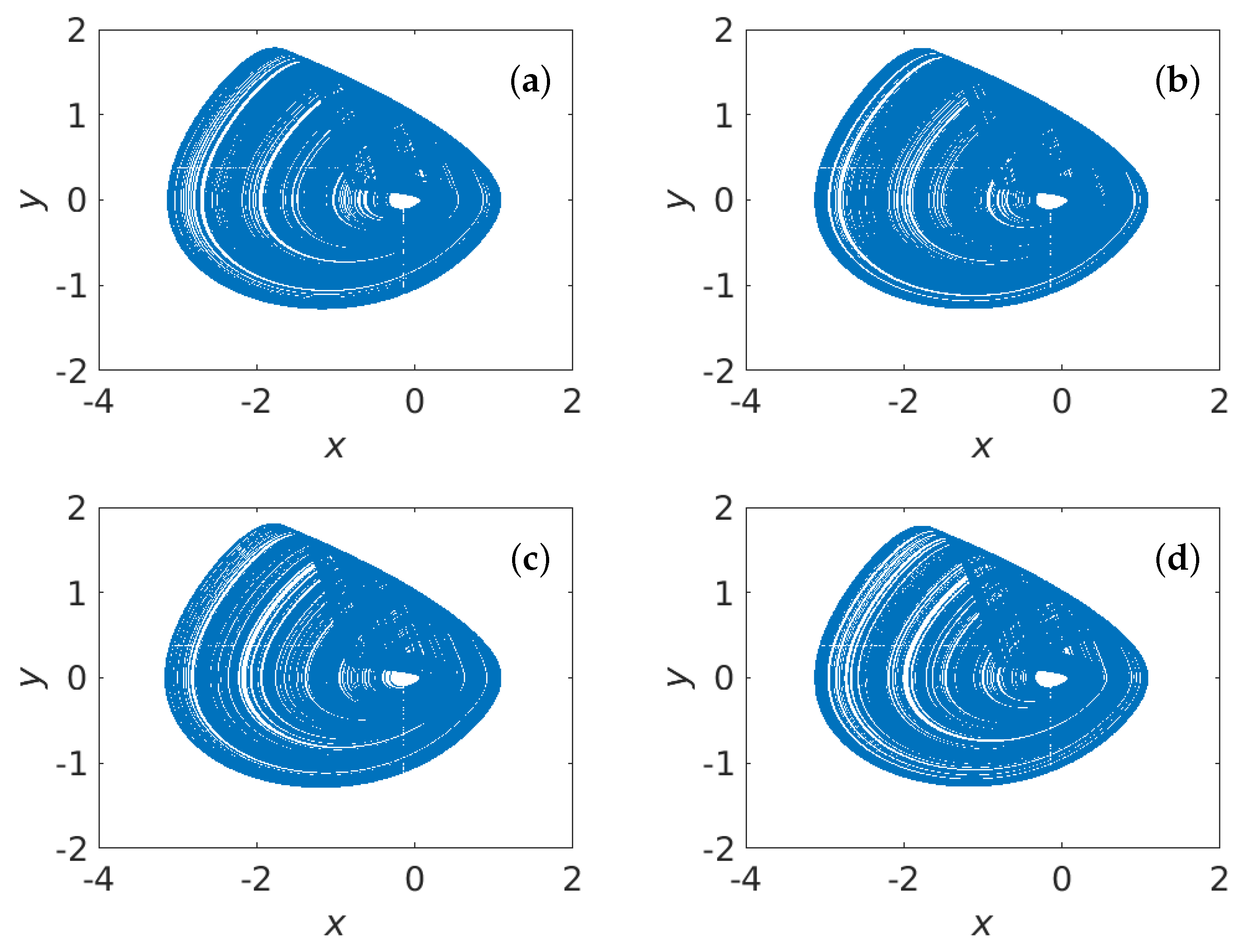
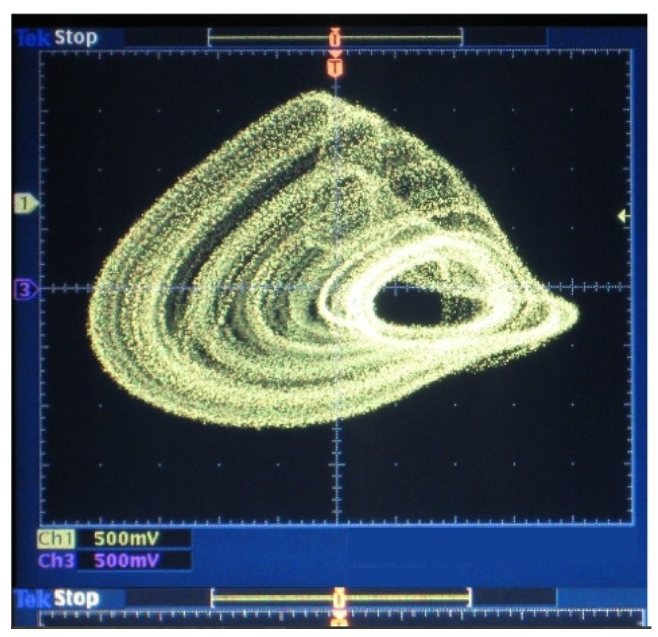
The phase portraits obtained by Euler’s and Runge–Kutta’s fourth-order methods when C = 1 F , L = 3 H , β = 1.52 , and α = 0.6 are shown in Figure 3. All attractors are characterized by the same structure, which is similar to the one acquired for the system emulator in [35] and shown in Figure 4.
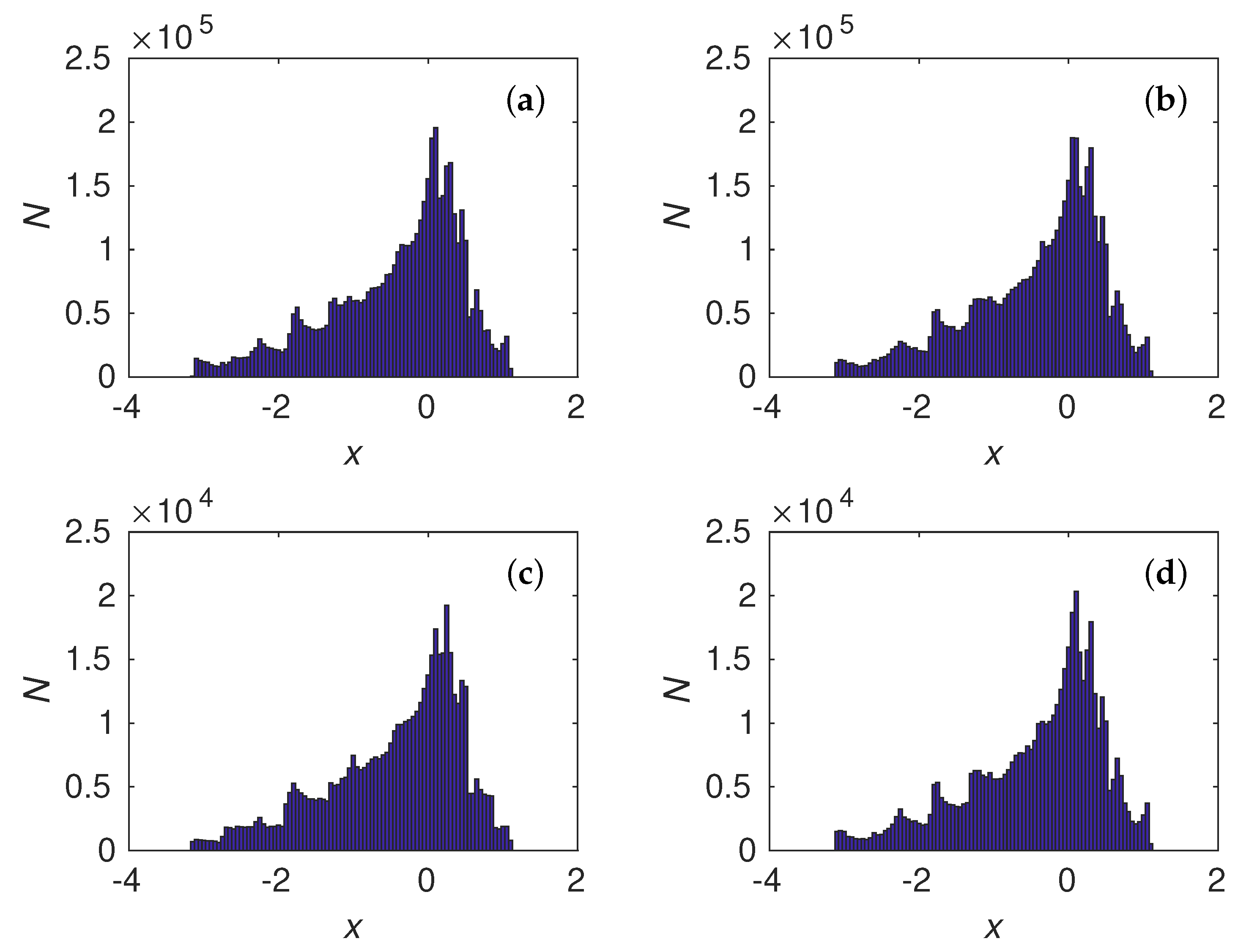
The histogram analyses of state variable x for different time steps and calculation methods are similar, as shown in Figure 5, indicating a saving of chaotic time series properties and the fractal dimension of the system.

3. Generating of Pseudorandom Sequences

3.1. Time Series Balance Property

Original time series of chaotic systems usually have an uneven distribution, as can be seen in Figure 5, and a strong correlation between adjacent points. Therefore, such sequences are not random. The balance property is one of the basic requirements of any periodic binary sequences that are used as a test for randomness [53].
The system (2) produces three output variables (i.e., signals): x, y, and z. All of them separately or together can be used to obtain a pseudo-random sequence. Each number in x, y, and z is a binary sequence of length M. In order to reach a uniform distribution, it is first necessary to discard several of the most significant bits. To determine the number of bits K that should be rejected, the balance property was used for a sequence of bits at the same position in the binary code of numbers. Dropping a part of the bits eliminates possible synchronization attacks, similar to that described in [54], the purpose of which is to determine generator parameters.
The matrix type (5) of size K × M was formed with elements x i , j , y i , j , and z i , j , i = 1 M , j = 1 K in order to pick up the bits with a better balance property:
a 1 , 1 , a 1 , 2 , , a 1 , j , , a 1 , M 1 , a 1 , M a 2 , 1 , a 2 , 2 , , a 2 , j , , a 2 , M 1 , a 2 , M a i , 1 , a i , 2 , , a i , j , , a i , M 1 , a i , M a K , 1 , a K , 2 , , a K , j , , a K , M 1 , a K , M
where K is the iteration numbers of variables x, y, or z, and M is the length of the bit string containing the chaotic number.
The binary matrix (5) is transformed into a new matrix with elements b i , j = a i , j a i + 1 , j . This transformation allows the detection of the correlation between the adjacent elements of the matrix columns (5).
For each column, the number of “0” symbols is N 0 and that of “1” symbols is N 1 ; thus, N 0 + N 1 = N is computed. The sequence can be random only if the quotient N 0 / N or N 1 / N is close to 0.5.
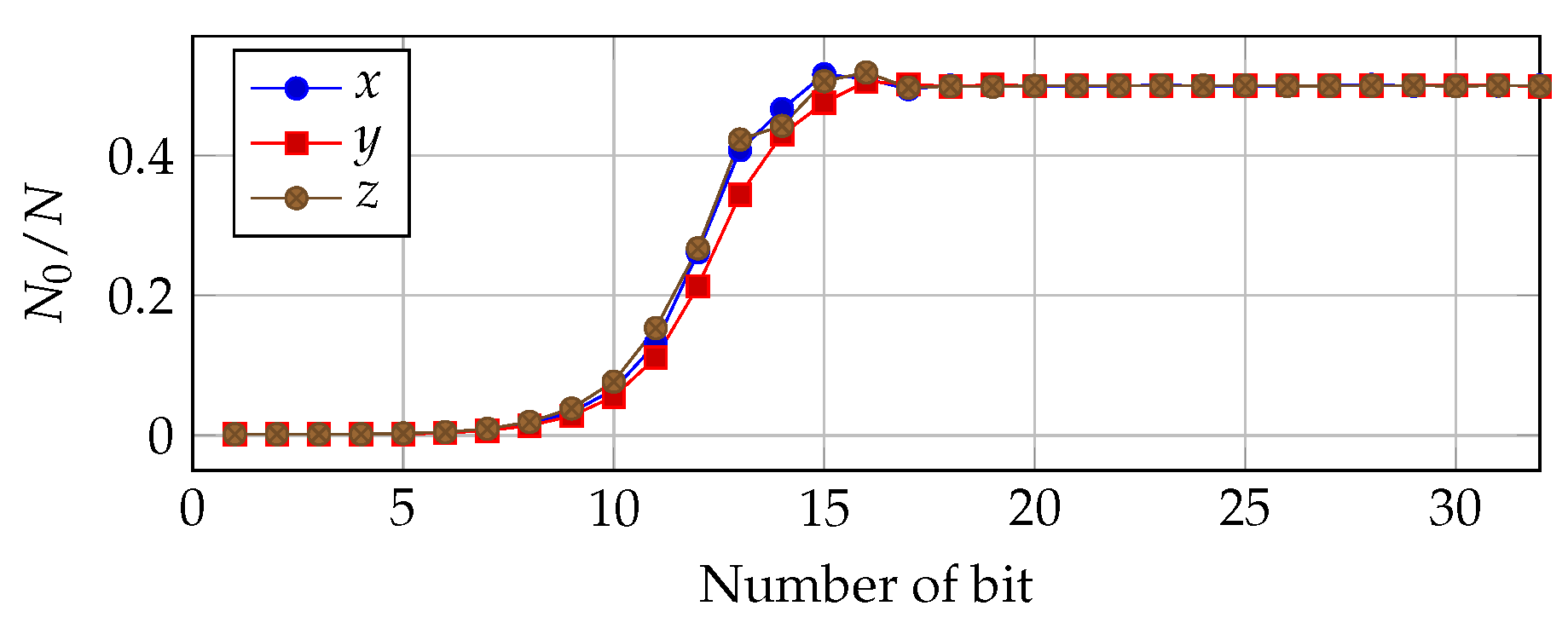
The balance of bits generated by (3) when Δ t = 0.001 using Q6.26 fixed-point arithmetic for variables x i , j , y i , j , and z i , j is shown in Figure 6. One bit is used to define the sign and 26 bits are used for the fractional part. As shown in Figure 6, only the bits from 17 to 32 have approximately the same number of “0”s and “1”s in a sequence. We must reject at least 16 of the most significant bits for each output to obtain a balanced sequence.
In the case of double-precision floating-point arithmetic and Runge–Kutta’s fourth-order method (4) and Δ t = 0.001 , it is necessary to remove at least the 22 most significant bits (Figure 7).
It is worth noting that bit balance depends not only on arithmetic precision, but also timestep Δ t is important. An increase of Δ t leads to a decreasing correlation between two sequential iterations and requires the rejection of a smaller number of most significant bits; however, this can lead to the collapse of chaotic dynamics [55].
The actions described above can be considered as a preliminary criterion for selecting pseudorandom bits from chaotic time sequences.

3.2. Design of CPRNG

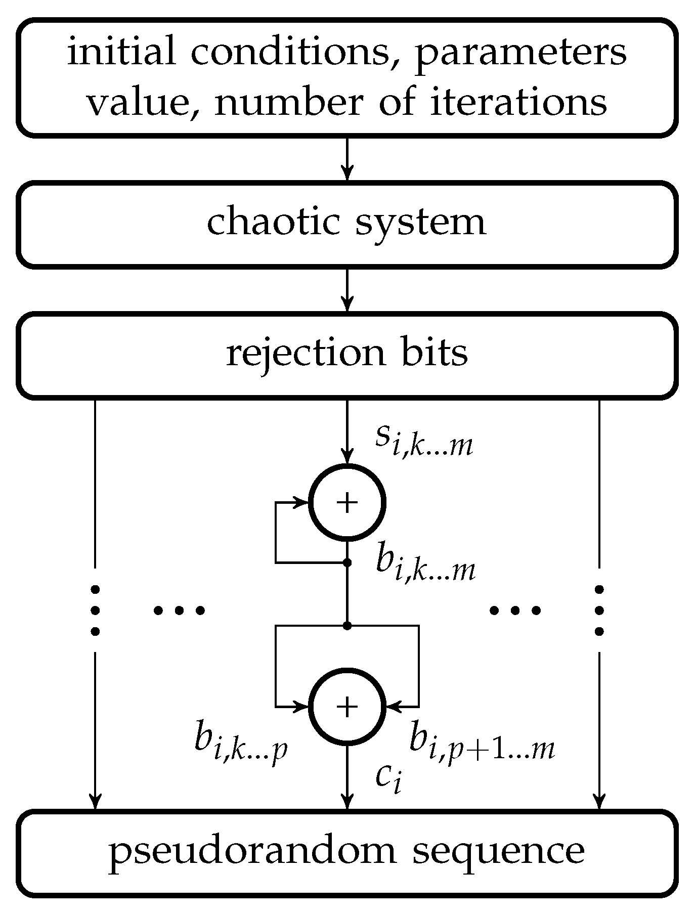
The general diagram for CPRNG from the output time series of chaotic systems is shown in Figure 8.
The initial conditions and parameter values are the keys of CPRNG, and they have to be chosen to provide the chaotic behavior of the system. Lyapunov exponents diagrams are useful for giving suitable parameter values. Iterations of the discretized chaotic system are performed K times to reach the required sequence length. The bit balance criterion is used to select the appropriate part from M bits for each time series. The XOR operation with feedback is applied to the selected bits s i , k m , which improves the statistical properties of the sequence b i , k m . The bit sequence b i , k m is divided into two identical-length subsequences b i , k p and b i , p + 1 m , which are added by modulo 2 such that c i = b i , k p b i , p + 1 m . The last operation due to XOR properties is non-invertible and makes it impossible to retrieve sequences b i , k m by the output pseudorandom sequence c i , thus hiding the state of the chaotic system at each iteration.
The applicability of the algorithm does not depend on the number of output system variables; therefore, it is possible to use an array of chaotic systems.

3.3. FPGA-Implementation

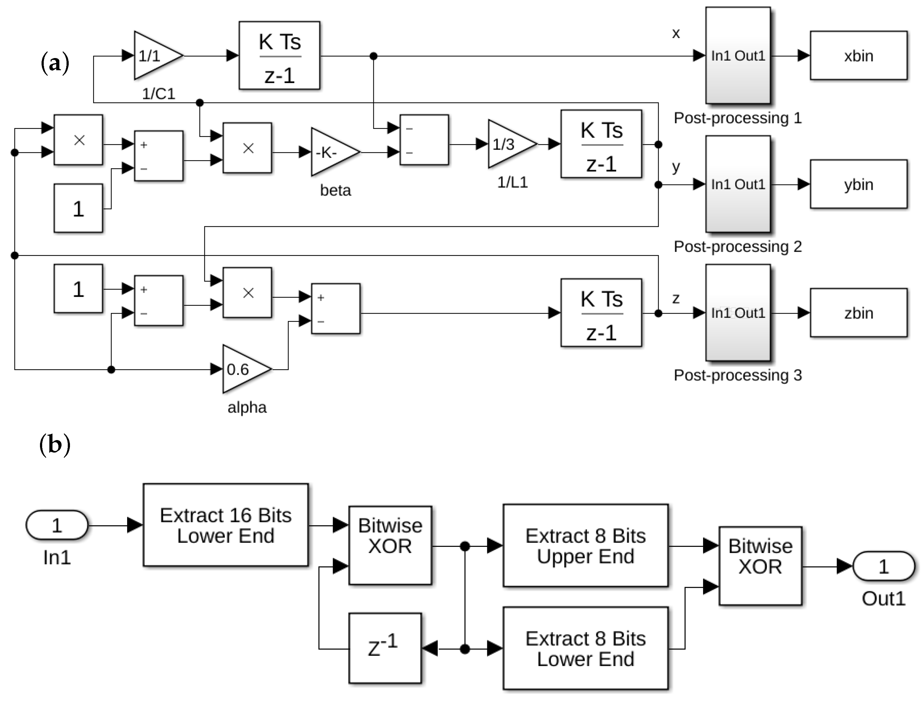
Figure 9 shows the Simulink model of the suggested algorithm developed for the Euler method. The pseudorandom binary sequences x b i n , y b i n , and z b i n occur after the post-processing of chaotic time series x, y, and z, respectively.
The Simulink-model based on system (2) and (3) was implemented on FPGA Cyclone IV EP4CE115 using an HDL-coder to generate Verilog code and FPGA-in-the-loop MATLAB tools for data capture from the target board. The target board DE2-115 with FPGA chip EP4CE115 was connected to a PC by an Ethernet interface.
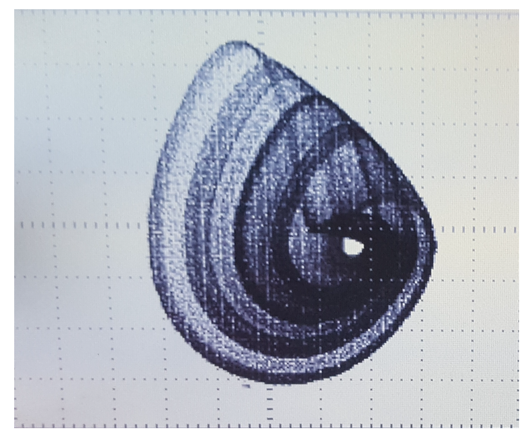
The chaotic attractor of the system (3) that was implemented on FPGA and transmitted through the VGA output on the DE2-115 board is shown in Figure 10. It is similar to the attractor in Figure 4.
If the developed generator is used as a separate module on FPGA with Q6.26 fixed-point arithmetic and the Euler method is used to solve ODEs, the speed of pseudorandom sequence generation can reach 1.2 Gbps at a clock frequency of 50 MHz.

3.4. Testing of CPRNG Based on One System

One of the most common statistical tests is the suite of statistical tests provided by the National Institute of Standards and Technology (NIST SP 800-2). This suite consists of 15 tests. A binary sequence is marked as statistically safe if all the tests are successfully passed [56].
Two test sequences were obtained for the Euler and fourth-order Runge–Kutta methods of numerical integration using the discrete model of the chaotic system.
We used the Euler method for ODEs (3), fixed-point calculation with rounding to zero, and an accuracy of 32 bits to implement the proposed CPRNG by FPGA. The format of a number was as follows:
  • 1 bit defined the sign;
  • 5 bits were used for the integer part;
  • 26 bits were used for the fractional part.
This partition was made to avoid overflow and distortion of the calculations.
According to the balance criterion (Figure 6), the bits from k = 17 to m = 32 of each output time series were selected for the following application. The pseudorandom sequence was formed by following the above-described algorithm (Figure 8). The last bitwise operation was performed with p = 24 between b 17 . . . 24 and b 25 . . . 32 . Accordingly, a sequence of 8 bits in length was obtained from each state variable, including 24 bits for one iteration of the chaotic system.
In the case of using the Runge–Kutta fourth-order method with double-precision binary floating-point precision, each chaotic system output yields a sequence of 64-bit lengths in format IEEE 764. The bits from k = 24 to m = 64 are picked up based on the balance (see Figure 7) for further post-processing. At the next stage, the result of the XOR operation between b i , 24 44 and b i , 45 64 forms a sequence of 20 bits. The 60 bit sequence for one iteration is obtained for the whole system. The Matlab-Simulink software was used in order to obtain pseudorandom sequences by Runge–Kutta’s fourth-order method.
To generate pseudorandom sequences, the following parameters were used: C = 1 F , L = 3.0 H , α = 0.6 , β = 1.52 , and Δ t = 0.01 . The NIST tests were performed on a binary sequence with a length of 10 9 bits, which was divided into 1000 subsequences (with 1 million bits each).
The results of testing pseudorandom sequences are shown in Table 1.
For both types of arithmetic, all tests were successfully passed. This confirms the feasibility of obtaining pseudorandom sequences through the application of the given method.

4. Coupled Memristive Structure-Based Chaotic Circuits for PRNG

4.1. Coupled Chaotic Systems without Synchronization

The enhancement of the CPRNG performance can be realized by combining two or more simple chaotic systems in a certain way. This results in a system with more complex behavior, numerous different variables, and control parameters.
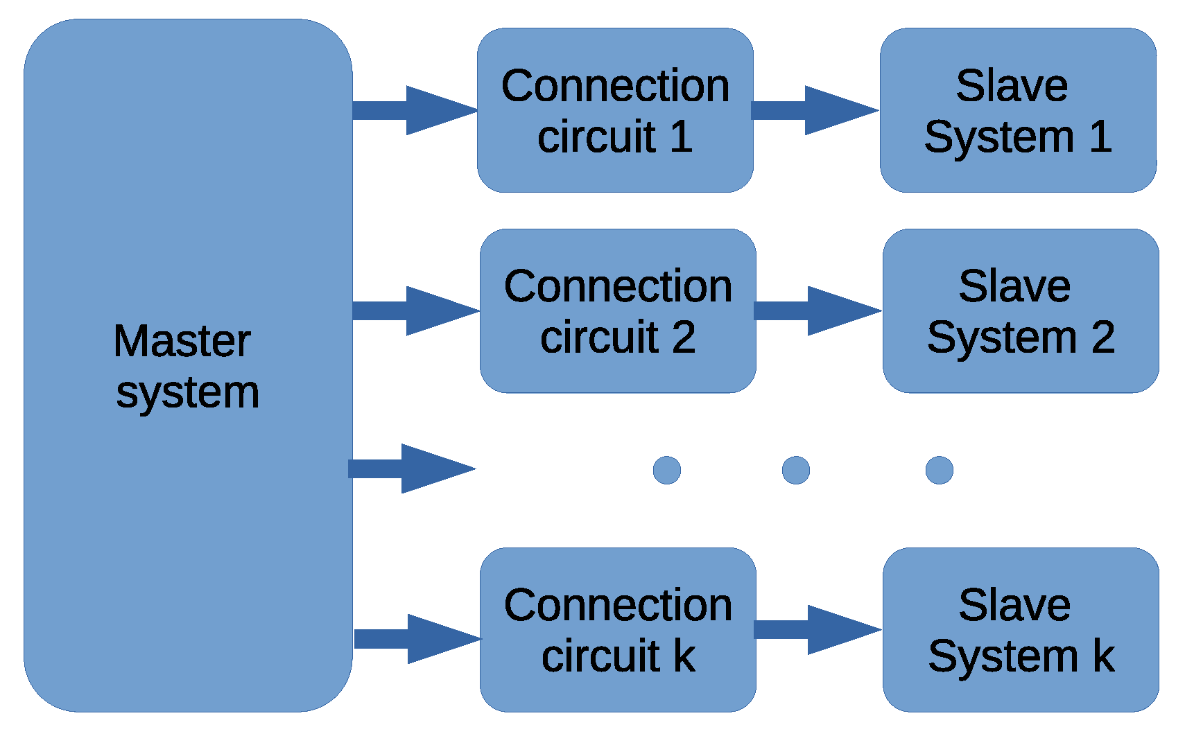
There are several approaches to coupling systems; in particular, unidirectional, bidirectional, ring, mixed, and so on [57,58]. All such coupling methods allow the occurrence of complete synchronization between systems when their outputs become identical. This situation is unacceptable for “good” CPRNG and should be avoided. We propose to use the master–slave configuration to increase the number of control parameters and output variables, as shown in Figure 11. The connection circuit is needed to ensure a unidirectional influence on the slave system. Several slave systems with different parameters and/or initial conditions can be used to achieve better performance in terms of the speed of pseudo-random sequence generation.
To define the absence or presence of complete synchronization, we use the theory of the conditional Lyapunov exponent as the test for stability [57,59]. The negative value of the largest conditional Lyapunov exponents is the required condition for the asymptotically stable behavior of the slave system.
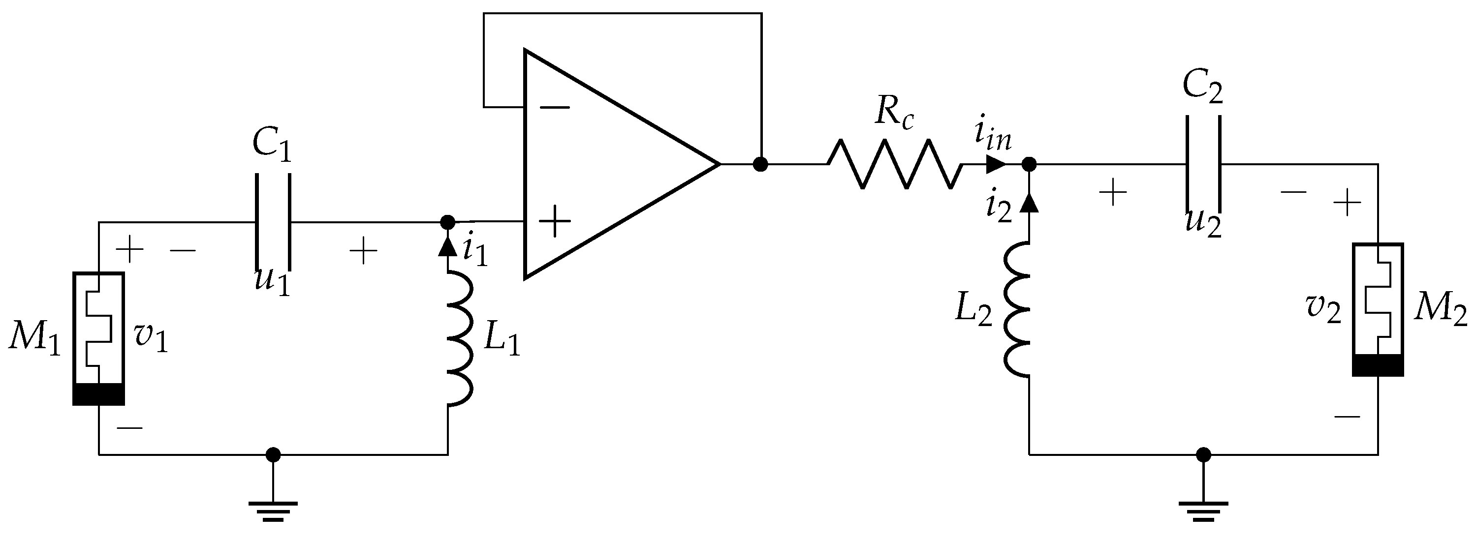
Let us consider two chaotic memristive systems that are unidirectionally coupled through a voltage buffer and resistor R c , as shown in Figure 12. The slave system does not affect the master system. The influence level of the master system on the slave system is determined by the resistor R c (R-coupling) and, depending on its value, the two systems can be synchronized. Using the Kirchhoff laws and Equation (1), we obtain the system of six differential equations:
d u 1 d t = i 1 C 1 d i 1 d t = u 1 + v 1 L 1 d z 1 d t = i 1 ( 1 z 1 ) α 1 z 1 d u 2 d t = i 2 + i i n C 2 d i 2 d t = u 2 + v 2 L 2 d z 2 d t = ( i 2 + i i n ) ( 1 z 2 ) α 2 z 2
where u 1 , 2 , i 1 , 2 , z 1 , 2 are the state variables, C 1 , 2 = 1 F , L 1 , 2 = 3 H , α 1 , 2 = 0.6 , β 1 , 2 = 1.52 are the system parameters, v 1 = β 1 ( z 1 2 1 ) i 1 , v 2 = β 2 ( z 2 2 1 ) ( i 2 + i i n ) , and i i n = u 1 + v 1 u 2 v 2 R c .
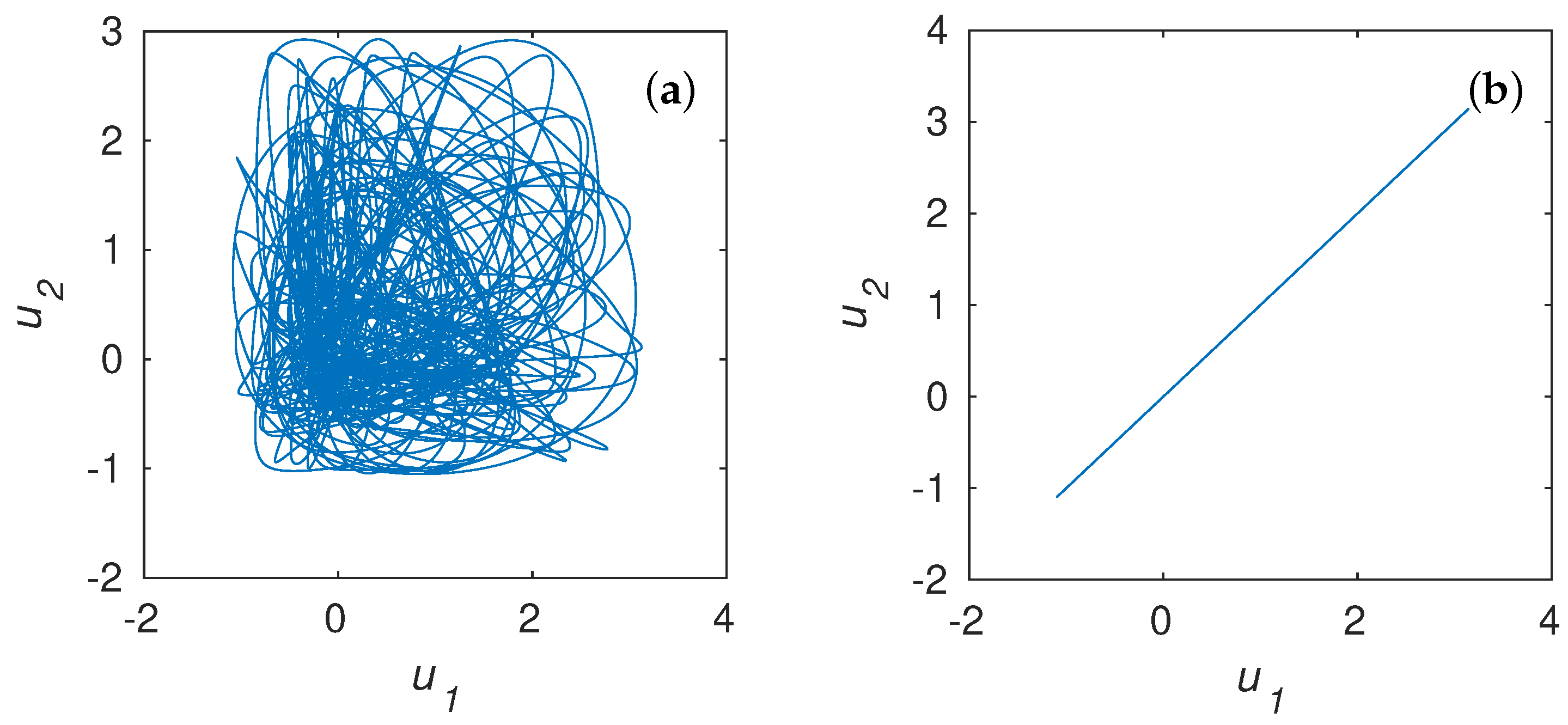
In Equation (6), the first three equations describe the master system and the last three describe the slave system. The relation between the dynamics of the master and the slave systems is illustrated in Figure 13. When R c = 40 Ohm, the conditional Lyapunov exponents of the slave system are λ 1 = 0.035 , λ 2 = 0.017 , and λ 3 = 0.581 ; the largest one is greater than zero, confirming the preservation of the chaotic behavior of coupled systems. The chaotic systems are not synchronized; their outputs differ from each other and can be applied to form PRNG.
It is worthwhile to notice that the second Lyapunov exponent of the driven system λ 2 = 0.017 is less than zero, which is non-conventional for a chaotic system. However, this can be explained as follows. The driven system is modified due to the presence of the connection circuit. This means that it is not identical to the drive system [60]. The resistor R c impacts on the dynamics of the driven system even when the input signal is absent. If a chaotic system exhibits chaotic behavior, the input signal can lead to the changing of Lyapunov exponents, as is shown in [60,61,62].
If R c = 3 Ohm, all of the conditional Lyapunov exponents are negative ( λ 1 = 0.018 , λ 2 = 0.228 , λ 3 = 0.745 ), proving the possibility of synchronization. The dependence of u 1 ( u 2 ) after the transient process is a straight line, and the output time series are the same and statistically compromised.
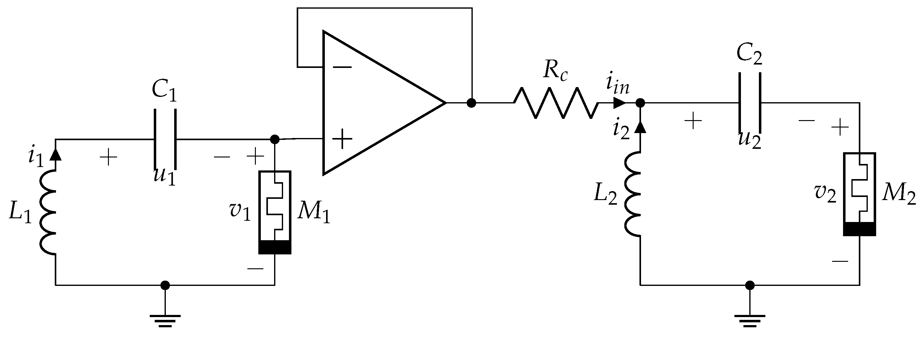
To avoid complete synchronization at an arbitrary value of R c , it is possible to modify the coupling as shown in Figure 14, where unequal points of the schemes are coupled. Then, at a nonzero value of the resistance R c , the state variables of the master and the slave system will be different. Consequently, it is possible to obtain more output state variables and increase the efficiency of the PRNG by combining several systems.
The mathematical model describing the two coupled systems in Figure 14 is identical to (6) except that i i n = v 1 u 2 v 2 R c . When R = 3 Ohm, the values of the conditional Lyapunov exponents are λ 1 = 0.114 , λ 2 = 0.199 , λ 3 = 0.564 . Although the largest conditional exponent is negative, the complete synchronization cannot be established due to the special connection.
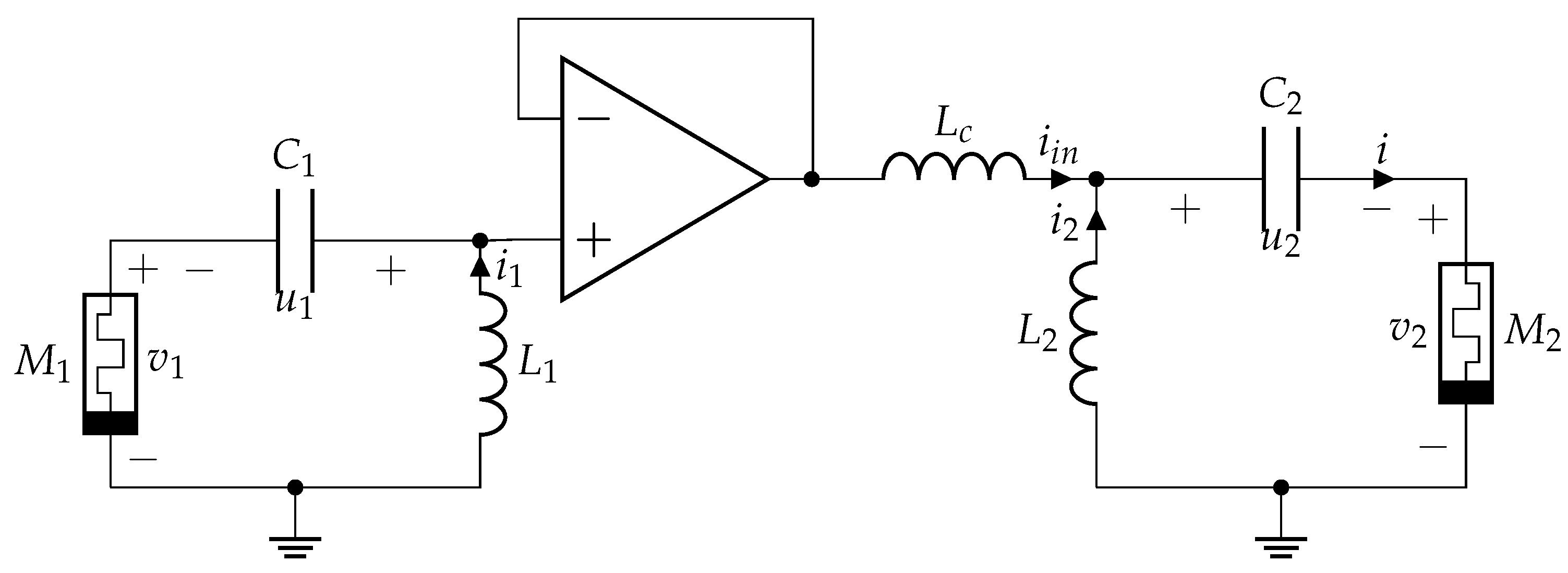
Another way to avoid complete synchronization is to use electric filters to connect the systems. In the simplest case, those are reactive elements (inductor or capacitor) instead of a dissipative connection through a resistor. The reactive element causes frequency-dependent distortions of the input signal of the slave system, and full synchronization cannot be possible. When two systems (2) are connected via an inductor (Figure 15), the coupled systems model is as shown in (7).
d u 1 d t = i 1 C 1 d i 1 d t = u 1 + v 1 L 1 d z 1 d t = i 1 ( 1 z 1 ) α 1 z 1 d u 2 d t = i 2 + i i n C 2 d i 2 d t = u 2 + v 2 L 2 d z 2 d t = ( i 2 + i i n ) ( 1 z 2 ) α 2 z 2 d i i n d t = u 1 + v 1 u 2 v 2 L c
where u 1 , 2 , i 1 , 2 , z 1 , 2 , i i n are state variables; C 1 , 2 = 1 F , L 1 , 2 = 3 H , α 1 , 2 = 0.6 and β 1 , 2 = 1.52 are the system parameters, v 1 = β ( z 1 2 1 ) i 1 , v 2 = β ( z 2 2 1 ) ( i 2 + i i n ) .
The last equation in (7) describes the connection via the inductor L c (L-coupling). The slave system is described by the last four equations in (7) and has four conditional Lyapunov exponents that are equal— λ 1 = 0 , λ 2 = 0.014 , λ 3 = 0.622 , and λ 4 = 1.4786 —when L c = 3 H . The largest exponent is zero, which indicates a limit cycle that represents the dynamics of the slave system.
The use of reactive elements for the coupling leads to the further complication of the system. Note that a dissipative coupling of non-equivalent points, or an inertial coupling, ensures the absence of only complete synchronization. A more complex type of chaotic synchronization, such as generalized synchronization, can be established between systems, and their states will be bound by a complex nonlinear dependence [58].

4.2. Testing of CPRNG Based on Coupled System

In order to demonstrate the effectivity of the models of coupled systems, two approaches were performed, including the coupling of non-equivalent points for R = 1 Ohm (Figure 14) and the inertial coupling via an inductive element for L c = 3 H (Figure 15). Euler’s method with a fixed point of 32 bits was utilized for the models of differential equations corresponding to the algorithm shown in Figure 8.
The bits from 17 to 32 were picked up from all of the output sequences of chaotic numbers for the post-processing. The sequences with a length of 10 9 were obtained for the testing, which was carried out using NIST. The testing results are shown in Table 2. One can see that all statistical tests were successfully passed for both cases.
Finally, the described approach of CPRNG modeling can be applicable for other continuous chaotic systems, but it is necessary to perform extra investigations.

5. Application

5.1. Image Encryption

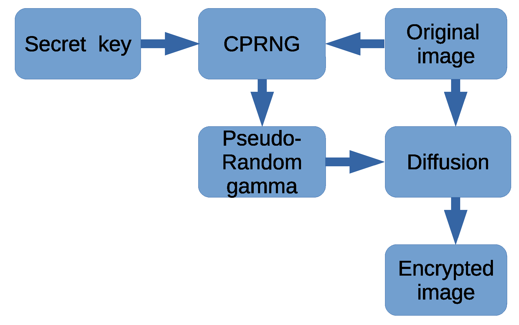
The proposed method of generating pseudorandom sequences can be used to encrypt any information that is transformable to a bitstream such as digital audio and video, text, image, etc. Here, we show the application of CPRNG to image encryption. The typical way to encrypt information by a symmetric stream cipher is shown in Figure 16. When PRNG is based only on one chaotic system, the process of generating a keystream starts with a secret key, which is the initial condition, and parameters for (2). Diffusion will continue a typical classical scheme by adding a modulo 2 binary keystream and information stream.
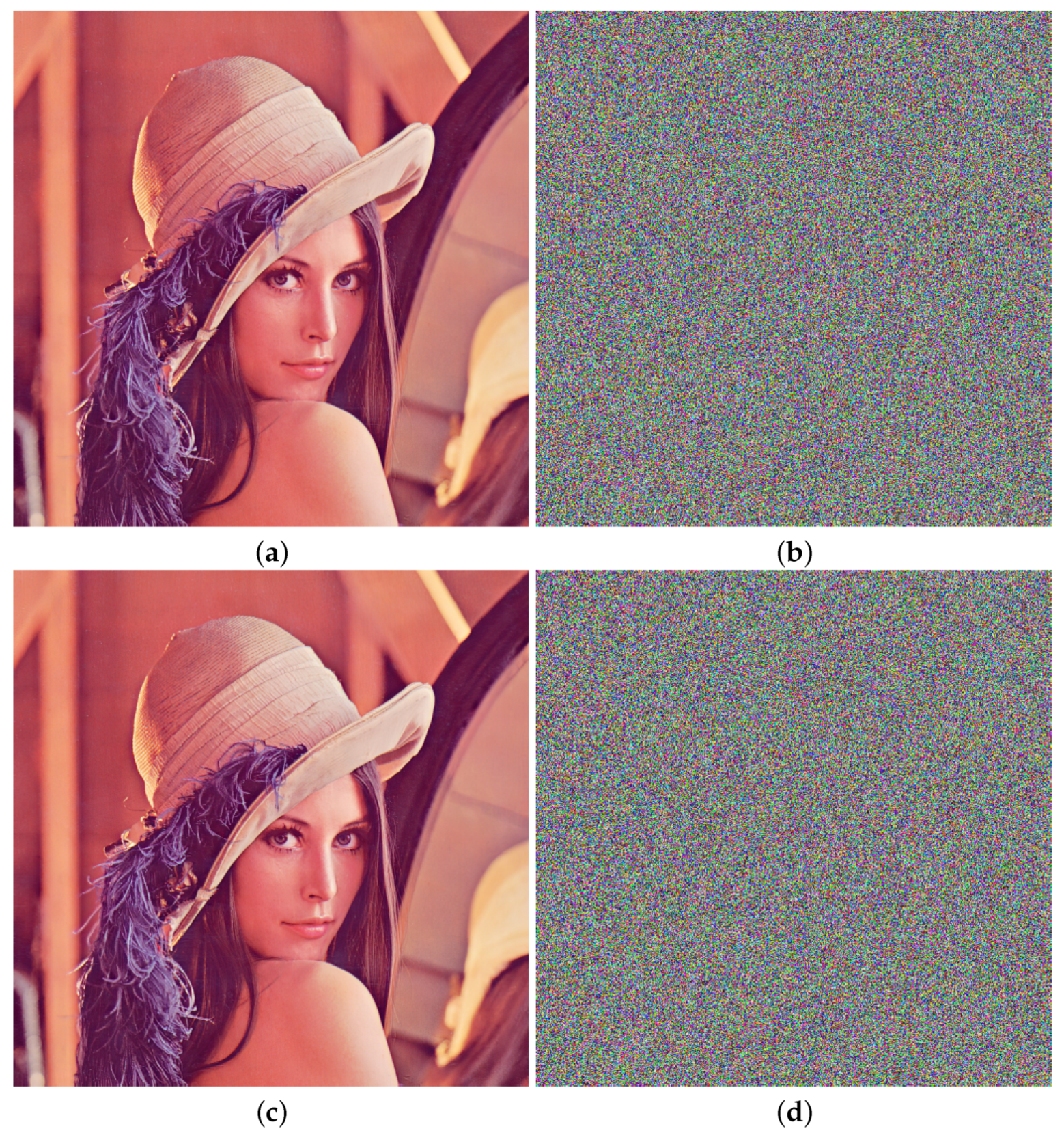
To obtain the pseudorandom sequence for image encryption, we used the following parameters: C = 1 F , L = 3.0 H , β = 1.5 , α = 0.5 , and a double-precision floating-point format performed according to the procedure described in Section 3.2 with k = 24 , m = 64 , and p = 44 . The size of test image Lena is 512 × 512 pixels (see Figure 17a).
In Figure 17b, the encrypted test image is shown. The comparison of histograms of the original and encrypted image (see Figure 18 and Figure 19) shows the transformation from nonuniform to nearly uniform distributions. Figure 19 confirms that the histogram analysis cannot provide any clue to break the algorithm by statistical attacks on the encrypted image as all the statistical information of the original image is lost after the encryption.
The correlation between components of color for the test image and encrypted image is 0.0030 for component R, −0.0011 for G, and 0.0018 for B. The average pixel color value of the original image is equal to 94.6445, and it changes to 127.5359 for the encrypted image, which confirms an even distribution of colors. Moreover, there are no observed color image contours as diffusion applies independently for each pixel, as shown in Figure 17b.
Sensitivity to the initial condition suggests that any key from the keyspace is equal and valid. The smallest change of the key (initial condition and parameters) should make correct encryption impossible. Figure 17d and Figure 20 show the failure of encryption when there is a difference in the x ( 0 ) equal to 2 35 . The correlation between components of color in the original image (Figure 17a) and decrypted image in Figure 17d are equal to 0.0169 for red, −0.0007 for green, and −0.0005 for blue components. The average pixel color value of the encrypted image is 127.5897, and this confirms that the proposed method is sensitive to initial conditions.

5.2. Security Analysis

The security of the suggested encryption algorithm is guaranteed by the security of a generator due to the stream method being utilized. The inefficiency of the static approach to non-authorized decryption is approved by the successfully passed NIST STS tests. The analysis of the histograms and pixel correlation is an extra confirmation of the security of the image encryption.
Key space estimation. When only one chaotic system is used, the encryption key consists of five sub keys: three initial conditions— ( x ( 0 ) , y ( 0 ) , z ( 0 ) ) —and four parameters—L, C, α , and β —of the chaotic system (2). The size of the keyspace is defined by a number of valid different values of these sub-keys. The values of the initial conditions are restricted with regard to the sensitivity of the encryption algorithm to their changeability and is ( 2 35 ) n , where n = 3 , for a three-dimensional system. The system’s parameter values impact its dynamics for each iteration, providing, in this case, minimal sensitivity to the parameter changes. The computational precision following the IEEE 754 binary floating-point format includes 52 explicitly stored bits [63]. Henceforth, there are ( 2 52 ) 4 different values for four parameters. For a three-dimensional memristive structure-based chaotic system, the number of secret keys is ( 2 35 ) 3 ( 2 52 ) 4 = 2 313 .
In the case of a few chaotic systems being used, as shown in Figure 11, which are connected by one of the methods proposed in Section 4, the number of sub-keys increases because of the connection parameter R c or L c and state variable i i n for an inductive coupling. For the connection via a resistor, the five parameters L 2 , C 2 , α 2 , β 2 , and R c and three initial conditions ( u 2 ( 0 ) , i 2 ( 0 ) , z 2 ( 0 ) ) are the additional sub-keys; for the connection via an inductor, the five parameters L 2 , C 2 , α 2 , β 2 , and L c and four initial ( u 2 ( 0 ) , i 2 ( 0 ) , z 2 ( 0 ) , i i n ( 0 ) ) conditions are the additional factors. Thus, the connection scheme of a one drive-one driven system provides the keyspace 2 313 ( 2 35 ) 3 ( 2 52 ) 5 = 2 313 2 365 = 2 678 for a six-dimensional R-coupled system and 2 313 ( 2 35 ) 4 ( 2 52 ) 5 = 2 313 2 400 = 2 713 for a seven-dimensional L-coupled system.
For k additional slave systems and R-coupling, the keyspace is increased to 2 313 ( 2 365 ) k . In case of L-coupling, the number of keys is equal to 2 313 ( 2 400 ) k . This result shows a larger keyspace than that obtained for the fractional-order hyperchaotic system (FOHS) [41]. A FOHS supports the key space of ( 2 52 ) 7 + n , where n is the dimension of the system. In the proposed method, the number of keys of FOHS is ( 2 52 ) 7 + 6 = 2 676 for n = 6 , which means k = 1 . This is less than provided within our method for the six-dimensional system. It can be seen that the difference becomes more significant with the increase of the system dimension. Such a larger keyspace enhances protection against brute-force attacks.
In addition, it is evident from histogram analysis that the distribution of colors in the encrypted image is closer to uniform than in [41,42].

6. Conclusions

In the paper, the model of a memristive structure-based chaotic system is used to create CPRNG. Two methods of numerical simulation—Euler’s and Runge–Kutta’s—were applied and investigated to transform the model of differential equations into a discrete system. This transformation was conducted to find a timestep that does not lead to the collapsing of chaotic time series.
The bit balance criterion for separating random and non-random parts of the binary representation of chaotic time series was suggested. After applying bit balance to chaotic time series, the simple post-processing technique based on two XOR operations allows all the NIST SP 800-22 statistical tests to be passed. Nevertheless, we admit the possibility of using more complex post-processing algorithms.
The special connections of simple chaotic systems to arrays that exclude the complete synchronization are proposed in order to improve the quality of CPRNG and make it scalable taking into account the available resources. This is the practical methodology to design a high-dimensional chaotic system for CPRNG.
The keyspace of CPRNG with one memristive structure-based system is equal to 2 313 . Increasing the dimension of the chaotic system by the special connections of k slave subsystems enlarges the number of keys up to 2 313 ( 2 365 ) k for R-coupling and 2 313 ( 2 400 ) k for L-coupling.
The FPGA implementation of the proposed method for the creation of pseudo-random sequences confirmed the possibility of using it in real-time applications. The symmetric image encryption is presented as an illustrative example of the practical use of the proposed method of generating pseudorandom sequences.

Author Contributions

Conceptualization, S.H.; Investigation, S.H., O.K. and D.V.; Methodology, O.K.; Supervision, F.C.; Writing—original draft, S.H. and D.V. All authors have read and agreed to the published version of the manuscript.

Funding

This work was supported by the Ministero dell’Istruzione, dell’Universitá e della Ricerca (MIUR) under Contract 2017LSCR4K-003.

Data Availability Statement

Data is available upon request.

Conflicts of Interest

The authors declare no conflict of interest.

References

  1. Kocamaz, U.E.; Çiçek, S.; Uyaroǧlu, Y. Secure Communication with Chaos and Electronic Circuit Design Using Passivity-Based Synchronization. J. Circuits Syst. Comput. 2018, 27, 1850057. [Google Scholar] [CrossRef]
  2. Uchida, A. Optical Communication with Chaotic Lasers: Applications of Nonlinear Dynamics and Synchronization; John Wiley & Sons: Hoboken, NJ, USA, 2012. [Google Scholar]
  3. Eisencraft, M.; Attux, R.; Suyama, R. Chaotic Signals in Digital Communications; CRC Press: Boca Raton, FL, USA, 2018. [Google Scholar]
  4. Kocarev, L.; Lian, S. Chaos-Based Cryptography: Theory, Algorithms and Applications; Springer Science & Business Media: Berlin/Heidelberg, Germany, 2011; Volume 354. [Google Scholar]
  5. James, A. An overview of memristive cryptography. Eur. Phys. J. Spec. Top. 2019, 228, 2301–2312. [Google Scholar] [CrossRef]
  6. Ergün, S.; Özoguz, S. Truly random number generators based on non-autonomous continuous-time chaos. Int. J. Circuit Theory Appl. 2010, 38, 1–24. [Google Scholar] [CrossRef]
  7. Rodriguez-Vazquez, A.; Delgado-Restituto, M. CMOS design of chaotic oscillators using state variables: A monolithic Chua’s circuit. IEEE Trans. Circuits Syst. II Analog Digit. Signal Process. 1993, 40, 596–613. [Google Scholar] [CrossRef]
  8. Callegari, S.; Rovatti, R.; Setti, G. Embeddable ADC-based true random number generator for cryptographic applications exploiting nonlinear signal processing and chaos. IEEE Trans. Signal Process. 2005, 53, 793–805. [Google Scholar] [CrossRef]
  9. Valtierra, J.L.; Tlelo-Cuautle, E.; Rodríguez-Vázquez, A. A switched-capacitor skew-tent map implementation for random number generation. Int. J. Circuit Theory Appl. 2017, 45, 305–315. [Google Scholar] [CrossRef]
  10. Addabbo, T.; Alioto, M.; Fort, A.; Rocchi, S.; Vignoli, V. A feedback strategy to improve the entropy of a chaos-based random bit generator. IEEE Trans. Circuits Syst. I Regul. Pap. 2006, 53, 326–337. [Google Scholar] [CrossRef]
  11. Yu, F.; Li, L.; Tang, Q.; Cai, S.; Song, Y.; Xu, Q. A Survey on True Random Number Generators Based on Chaos. Discret. Dyn. Nat. Soc. 2019, 2019, 25451237. [Google Scholar] [CrossRef]
  12. Gao, Y.; Hua, S.H.; Du, X.L. FPGA-Based Logistic Chaotic Pseudo-Random Sequence Generator Design. In Proceedings of the 2020 5th International Conference on Mechanical, Control and Computer Engineering (ICMCCE), Harbin, China, 25–27 December 2020; pp. 834–837. [Google Scholar]
  13. Cang, S.; Kang, Z.; Wang, Z. Pseudo-random number generator based on a generalized conservative Sprott-A system. Nonlinear Dyn. 2021, 104, 827–844. [Google Scholar] [CrossRef]
  14. Rezk, A.A.; Madian, A.H.; Radwan, A.G.; Soliman, A.M. Multiplierless chaotic Pseudo random number generators. AEU—Int. J. Electron. Commun. 2020, 113, 152947. [Google Scholar] [CrossRef]
  15. François, M.; Defour, D.; Negre, C. A Fast Chaos-Based Pseudo-Random Bit Generator Using Binary64 Floating-Point Arithmetic. Informatica 2014, 38, 115–124. [Google Scholar]
  16. Erdem, E.; Garipcan, A.M. Hardware Implementation of Chaotic Zigzag Map Based Bitwise Dynamical Pseudo Random Number Generator on Field-Programmable Gate Array. J. Microelectron. Electron. Components Mater. 2020, 50, 243–253. [Google Scholar]
  17. Hobincu, R.; Datcu, O. A Novel Chaos Based PRNG Targeting Secret Communication. In Proceedings of the 2018 International Conference on Communications (COMM), Singapore, 24–26 February 2018; pp. 459–462. [Google Scholar]
  18. Moysis, L.; Tutueva, A.; Volos, C.K.; Butusov, D. A Chaos Based Pseudo-Random Bit Generator Using Multiple Digits Comparison. Chaos Theory Appl. 2020, 2, 58–68. [Google Scholar]
  19. Lorenz, E.N. Deterministic nonperiodic flow. J. Atmos. Sci. 1963, 20, 130–141. [Google Scholar] [CrossRef] [Green Version]
  20. Rössler, O.E. An equation for continuous chaos. Phys. Lett. A 1976, 57, 397–398. [Google Scholar] [CrossRef]
  21. Sprott, J.C. Some simple chaotic flows. Phys. Rev. E 1994, 50, R647. [Google Scholar] [CrossRef]
  22. Chua, L. Memristor-The missing circuit element. IEEE Trans. Circuit Theory 1971, 18, 507–519. [Google Scholar] [CrossRef]
  23. Strukov, D.; Snider, G.; Stewart, D.; Williams, R.S. The missing memristor found. Nature 2008, 453, 80–83. [Google Scholar] [CrossRef]
  24. Tetzlaff, R. Memristors and Memristive Systems; Springer: New York, NY, USA, 2014. [Google Scholar]
  25. Soell, C.; Reichenbach, M.; Roeber, J.; Hagelauer, A.; Weigel, R.; Fey, D. Case study on memristor-based multilevel memories. Int. J. Circuit Theory Appl. 2018, 46, 99–112. [Google Scholar] [CrossRef]
  26. Corinto, F.; Ascoli, A.; Gilli, M. Nonlinear Dynamics of Memristor Oscillators. IEEE Trans. Circuits Syst. I Regul. Pap. 2011, 58, 1323–1336. [Google Scholar] [CrossRef]
  27. Corinto, F.; Forti, M. Nonlinear dynamics of memristor oscillators via the flux-charge analysis method. In Proceedings of the 2017 IEEE International Symposium on Circuits and Systems (ISCAS), Baltimore, MD, USA, 28–31 May 2017; pp. 1–4. [Google Scholar]
  28. Brenna, A.; Corinto, F.; Noori, S.; Ormellese, M.; Pedeferri, M.; Diamanti, M.V. Memristive Anodic Oxides: Production, Properties and Applications in Neuromorphic Computing. In Advances in Memristor Neural Networks; Ciufudean, C., Ed.; IntechOpen: Rijeka, Croatia, 2018; Chapter 3. [Google Scholar]
  29. Ascoli, A.; Slesazeck, S.; Mähne, H.; Tetzlaff, R.; Mikolajick, T. Nonlinear Dynamics of a Locally-Active Memristor. IEEE Trans. Circuits Syst. I Regul. Pap. 2015, 62, 1165–1174. [Google Scholar] [CrossRef]
  30. Ascoli, A.; Tetzlaff, R.; Chua, L.O.; Strachan, J.P.; Williams, R.S. History Erase Effect in a Non-Volatile Memristor. IEEE Trans. Circuits Syst. I Regul. Pap. 2016, 63, 389–400. [Google Scholar] [CrossRef]
  31. Muthuswamy, B.; Kokate, P.P. Memristor-Based Chaotic Circuits. IETE Tech. Rev. 2009, 26, 417–429. [Google Scholar] [CrossRef] [Green Version]
  32. Kyriakides, E.; Georgiou, J. A Compact, Low-frequency, Memristor-based Oscillator. Int. J. Circuit Theory Appl. 2015, 43, 1801–1806. [Google Scholar] [CrossRef]
  33. Rajagopal, K.; Karthikeyan, A.; Duraisamy, P. Difference equations of a memristor higher order hyperchaotic oscillator. Afr. J. Sci. Technol. Innov. Dev. 2018, 10, 279–285. [Google Scholar] [CrossRef]
  34. Hezayyin, H.G.; Ahmed, G.M.; Fouda, M.E.; Said, L.A.; Madian, A.H.; Radwan, A.G. A generalized family of memristor-based voltage controlled relaxation oscillator. Int. J. Circuit Theory Appl. 2018, 46, 1311–1327. [Google Scholar] [CrossRef]
  35. Muthuswamy, B.; Chua, L.O. Simplest chaotic circuit. Int. J. Bifurc. Chaos 2010, 20, 1567–1580. [Google Scholar] [CrossRef]
  36. Wu, R.; Wang, C. A New Simple Chaotic Circuit Based on Memristor. Int. J. Bifurc. Chaos 2016, 26, 1650145. [Google Scholar] [CrossRef]
  37. Volos, C.K.; Pham, V.T.; Nistazakis, H.E.; Stouboulos, I.N. A Dream that has Come True: Chaos from a Nonlinear Circuit with a Real Memristor. Int. J. Bifurc. Chaos 2020, 30, 2030036. [Google Scholar] [CrossRef]
  38. Ren, X.; Chen, B.; Xu, Q.; Wu, H.; Chen, M. Parameter and initial offset boosting dynamics in two-memristor-based Colpitts system. Eur. Phys. J. Spec. Top. 2021, 230, 1709–1721. [Google Scholar] [CrossRef]
  39. Borah, M.; Roy, B.K. Hidden multistability in four fractional-order memristive, meminductive and memcapacitive chaotic systems with bursting and boosting phenomena. Eur. Phys. J. Spec. Top. 2021, 230, 1773–1783. [Google Scholar] [CrossRef]
  40. Ontañón-García, L.J.; García-Martínez, M.; Campos-Cantón, E.; Čelikovský, S. Grayscale image encryption using a hyperchaotic unstable dissipative system. In Proceedings of the 8th International Conference for Internet Technology and Secured Transactions (ICITST-2013), London, UK, 9–12 December 2013; pp. 503–507. [Google Scholar]
  41. Borah, M.; Roy, B.K. Systematic construction of high dimensional fractional-order hyperchaotic systems. Chaos Solitons Fractals 2020, 131, 109539. [Google Scholar] [CrossRef]
  42. Asgari-Chenaghlu, M.; Balafar, M.A.; Feizi-Derakhshi, M.R. A novel image encryption algorithm based on polynomial combination of chaotic maps and dynamic function generation. Signal Process. 2019, 157, 1–13. [Google Scholar] [CrossRef]
  43. Lynnyk, V.; Sakamoto, N.; Čelikovský, S. Pseudo random number generator based on the generalized Lorenz chaotic system. IFAC-PapersOnLine 2015, 48, 257–261. [Google Scholar] [CrossRef]
  44. Machicao, J.; Bruno, O.M. Improving the pseudo-randomness properties of chaotic maps using deep-zoom. Chaos Interdiscip. J. Nonlinear Sci. 2017, 27, 053116. [Google Scholar] [CrossRef]
  45. Zhou, Y.; Hua, Z.; Pun, C.M.; Chen, C.L. Cascade Chaotic System with Applications. IEEE Trans. Cybern. 2015, 45, 2001–2012. [Google Scholar] [CrossRef]
  46. Yu, F.; Li, L.; He, B.; Liu, L.; Qian, S.; Zhang, Z.; Shen, H.; Cai, S.; Li, Y. Pseudorandom number generator based on a 5D hyperchaotic four-wing memristive system and its FPGA implementation. Eur. Phys. J. Spec. Top. 2021, 230, 1763–1772. [Google Scholar] [CrossRef]
  47. Lozi, R. Cryptography-Based Chaos via Geometric Undersampling of Ring-Coupled Attractors. In Mathematical Models, Methods and Applications; Siddiqi, A.H., Manchanda, P., Bhardwaj, R., Eds.; Springer: Berlin/Heidelberg, Germany, 2015; pp. 1–30. [Google Scholar]
  48. Garasym, O.; Taralova, I.; Lozi, R. Key requirements for the design of robust chaotic PRNG. In Proceedings of the 2016 11th International Conference for Internet Technology and Secured Transactions (ICITST), Barcelona, Spain, 5–7 December 2016; pp. 33–38. [Google Scholar]
  49. Cho, K.; Miyano, T. Design and Test of Pseudorandom Number Generator Using a Star Network of Lorenz Oscillators. Int. J. Bifurc. Chaos 2017, 27, 1750184. [Google Scholar] [CrossRef] [Green Version]
  50. Wu, Q. A Dependent Variable Exclusively Coupled Chaotic System for a Pseudorandom Bit Generator. In Proceedings of the 2018 4th Annual International Conference on Network and Information Systems for Computers (ICNISC), Wuhan, China, 19–21 April 2018; pp. 317–320. [Google Scholar]
  51. Chua, L.O.; Kang, S.M. Memristive devices and systems. Proc. IEEE 1976, 64, 209–223. [Google Scholar] [CrossRef]
  52. Wolf, A.; Swift, J.B.; Swinney, H.L.; Vastano, J.A. Determining Lyapunov exponents from a time series. Phys. D Nonlinear Phenom. 1985, 16, 285–317. [Google Scholar] [CrossRef] [Green Version]
  53. Sklar, B. Digital Communications: Fundamentals and Applications; Prentice Hall: Upper Saddle River, NJ, USA, 2001. [Google Scholar]
  54. Ergun, S. Analysis and Simulation of a Chaos-Based Random Number Generator for Applications in Security. In Proceedings of the 2017 International Symposium on Nonlinear Theory and Its Applications, NOLTA2017, Cancun, Mexico, 4–7 December 2017. [Google Scholar]
  55. Yuan, G.; Yorke, J. Collapsing of chaos in one dimensional maps. Phys. D Nonlinear Phenom. 2000, 136, 18–30. [Google Scholar] [CrossRef]
  56. Rukhin, A.; Soto, J.; Nechvatal, J.; Smid, M.; Barker, E. A Statistical Test Suite for Random and Pseudorandom Number Generators for Cryptographic Applications; Technical report; Booz-Allen and Hamilton Inc.: Mclean, VA, USA, 2001. [Google Scholar]
  57. Pecora, L.M.; Carroll, T.L.; Johnson, G.A.; Mar, D.J.; Heagy, J.F. Fundamentals of synchronization in chaotic systems, concepts, and applications. Chaos Interdiscip. J. Nonlinear Sci. 1997, 7, 520–543. [Google Scholar] [CrossRef] [Green Version]
  58. Boccaletti, S.; Kurths, J.; Osipov, G.; Valladares, D.; Zhou, C. The synchronization of chaotic systems. Phys. Rep. 2002, 366, 1–101. [Google Scholar] [CrossRef]
  59. Pecora, L.M.; Carroll, T.L. Driving systems with chaotic signals. Phys. Rev. A 1991, 44, 2374. [Google Scholar] [CrossRef] [PubMed]
  60. Hramov, A.E.; Koronovskii, A.A. Generalized synchronization: A modified system approach. Phys. Rev. E 2005, 71, 067201. [Google Scholar] [CrossRef] [PubMed] [Green Version]
  61. Balcerzak, M.; Chudzik, A.; Stefanski, A. Properties of generalized synchronization in smooth and non-smooth identical oscillators. Eur. Phys. J. Spec. Top. 2020, 229, 2151–2165. [Google Scholar] [CrossRef]
  62. Fazanaro, F.I.; Suyama, R.; Soriano, D.C. Conditional lyapunov exponents for izhikevich neuronal model: Preliminary results. In Proceedings of the 2016 6th International Conference on Nonlinear Science and Complexity (NSC—2016), Niigata, Japan, 18–20 May 2016. [Google Scholar]
  63. Kahan, W. Lecture Notes on the Status of IEEE Standard 754 for Binary Floating-Point Arithmetic. 1996. Available online: http://http.cs.berkeley.edu/~wkahan/ieee754status/ieee.ps (accessed on 30 November 2021).
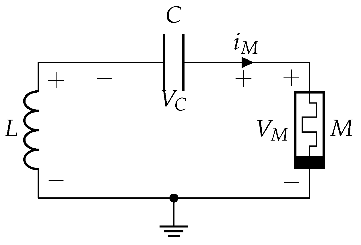
Figure 1. Electric scheme of simple memristive structure-based chaotic circuit.
Symmetry 14 00068 g001
Figure 2. The dependence of the Lyapunov exponents for (a) C = 1 F , β = 1.52 , α = 0.6 ; (b) L = 3 H , β = 1.52 , α = 0.6 ; (c) C = 1 F , L = 3 H , α = 0.6 .
Symmetry 14 00068 g002
Figure 3. Chaotic attractor of ( x , y ) -plane for system (2). (a,c) for Euler’s method; (b,d) for Runge–Kutta’s method. (a,b) are obtained for Δ t = 0.001 ; (c,d) are obtained for Δ t = 0.01 .
Symmetry 14 00068 g003
Figure 4. Chaotic attractor obtained by emulator in [35].
Symmetry 14 00068 g004
Figure 5. Histograms of distribution of ( x , y ) -plane for system (2). (a,c) for Euler’s method; (b,d) for Runge–Kutta’s method. (a,b) are obtained for Δ t = 0.001 ; (c,d) are obtained for Δ t = 0.01 .
Symmetry 14 00068 g005
Figure 6. The balance of bits generated by system (3) that is implemented by a Simulink-model using fixed-point arithmetic Q6.26.
Symmetry 14 00068 g006
Figure 7. The balance of bits in the binary representation of x, y, and z, which are generated by the system (4) implemented as the Simulink model with floating-point double-precision arithmetic.
Symmetry 14 00068 g007
Figure 8. The general scheme of CPRNG.
Symmetry 14 00068 g008
Figure 9. Simulink model of PRNG: (a) memristive chaotic circuit (2); (b) post-processing block.
Symmetry 14 00068 g009
Figure 10. Captured phase portrait of (2) obtained on FPGA.
Symmetry 14 00068 g010
Figure 11. Block scheme of unidirectional coupled chaotic system.
Symmetry 14 00068 g011
Figure 12. The scheme of two unidirectionally coupled systems.
Symmetry 14 00068 g012
Figure 13. Desynchronization when (a) R = 40 Ohm and (b) synchronization when R = 3 Ohm.
Symmetry 14 00068 g013
Figure 14. Schematic of systems with modified coupling.
Symmetry 14 00068 g014
Figure 15. Schematic of systems coupled through inductance.
Symmetry 14 00068 g015
Figure 16. Block scheme of the example of image encryption.
Symmetry 14 00068 g016
Figure 17. Image encryption: (a) original image, (b) encrypted image, (c) decrypted image, (d) decrypted image by changing the sub key x 0 on 2 35 .
Symmetry 14 00068 g017
Figure 18. Histogram of original image of (a) red, (b) green, and (c) blue components.
Symmetry 14 00068 g018
Figure 19. Histogram of encrypted image of (a) red, (b) green, and (c) blue components.
Symmetry 14 00068 g019
Figure 20. Histogram of encrypted image by changing sub key x ( 0 ) on 2 35 of (a) red, (b) green, and (c) blue components.
Symmetry 14 00068 g020
Table 1. NIST statistical tests results of PRNG.
Euler’s Method,
FPGA Implementation,
32-bits Fixed-Point
Arithmetic
Runge–Kutta Fourth Order
Method, Matlab-Simulink
Implementation, Double-Precision
Floating-Point Arithmetic
Testp-Value/ProportionStatusp-Value/ProportionStatus
FT0.504219/0.993Pass0.733899/0.986Pass
BFT0.922855/0.990Pass0.975644/0.987Pass
CST0.514124/0.993Pass0.305599/0.986Pass
CST0.811080/0.992Pass0.610070/0.987Pass
RuT0.757790/0.988Pass0.723804/0.988Pass
LRuT0.128132/0.990Pass0.969588/0.984Pass
RaT0.591409/0.991Pass0.713641/0.992Pass
FFT0.317565/0.990Pass0.494392/0.988Pass
NOTTAll 148 tests passedAll 148 tests are passed
OTT0.589341/0.984Pass0.142062/0.989Pass
UT0.118812/0.986Pass0.524101/0.991Pass
AET0.684890/0.986Pass0.508172/0.989Pass
RETAll 8 tests passedAll 8 tests are passed
REVTAll 18 tests passedAll 18 tests are passed
ST0.192724/0.987Pass0.686955/0.988Pass
ST0.182550/0.984Pass0.478839/0.993Pass
LCT0.522100/0.988Pass0.729870/0.987Pass
Table 2. NIST statistical tests results of PRNG.
Euler’s Method,
FPGA 32-bits Fixed-
Point Arithmetic
Implementation, Systems
with Modified Coupling (14)
Euler’s Method,
FPGA 32-bits Fixed-
Point Arithmetic
Implementation,
Systems Coupled
through Inductance (15)
Testp-Value/ProportionStatusp-Value/ProportionStatus
FT0.385543/0.991Pass0.946308/0.987Pass
BFT0.846338/0.990Pass0.016037/0.995Pass
CST0.473064/0.993Pass0.377007/0.989Pass
CST0.136499/0.991Pass0.904708/0.988Pass
RuT0.522100/0.986Pass0.244236/0.990Pass
LRuT0.014961/0.994Pass0.538182/0.990Pass
RaT0.141256/0.989Pass0.044508/0.989Pass
FFT0.486588/0.994Pass0.603841/0.987Pass
NOTTAll 148 tests are passedAll 148 tests passed
OTT0.146982/0.984Pass0.820143/0.990Pass
UT0.266235/0.986Pass0.257004/0.985Pass
AET0.662091/0.991Pass0.729870/0.985Pass
RETAll 8 tests passedAll 8 tests are passed
REVTAll 18 tests passedAll 18 tests are passed
ST0.028244/0.998Pass0.943242/0.993Pass
ST0.358641/0.990Pass0.607993/0.989Pass
LCT0.422638/0.992Pass0.834308/0.997Pass
Publisher’s Note: MDPI stays neutral with regard to jurisdictional claims in published maps and institutional affiliations.