Abstract
This paper presents an efficiency optimization controller for a permanent magnet synchronous motor (PMSM) of an electric vehicle. A new loss model is obtained based on the permanent magnet synchronous motor’s energy balance equation utilizing the theory of the port-controlled Hamiltonian system. Since the energy balance equation is just the power loss of the PMSM, which provides great convenience for us to use the energy method for efficiency optimization. Then, a new loss minimization algorithm (LMA) is designed based on the new loss model by adjusting the ratio of the excitation current in the d–q axis. Moreover, the proposed algorithm is achieved by the principle of the energy shape method of the Hamiltonian system. Simulations are finally presented to verify effectiveness. The main results of these simulations indicate that the dynamic performance of the drive is maintained and the efficiency increase is up to about 7% compared with the control algorithm, and about 4.5% compared with the conventional LMA at a steady operation of a PMSM.
1. Introduction
Electric vehicles, a significant part of sustainable transport, have attracted increasing attention [1,2,3]. An electric vehicle is a complex system that includes a wide range of technologies involving materials, machinery, power electronics, computer technology and other disciplines [4]. Unfortunately, there are many bottlenecks in the development of electric vehicles. EVs have low energy density and long charging times given present batteries. In addition, the optimum design of the motor, selection of a proper drive style and optimal control strategy are the other major factors [5,6]. The motor drive system is the key unit of energy conversion of electric vehicle. A. Haddoun utilized the stator flux as a control variable and proposed a strategy to minimize the losses of an induction motor propelling an electric vehicle [7]. Compared with induction motors, permanent-magnet synchronous motors (PMSMs) have many merits, such as high efficiency and high power density [8,9]. Many of the existing commercial electric vehicles are propelled by PMSMs [10,11]. Efficiency is an important index for EV traction systems. Therefore, developing an efficiency optimization strategy of the PMSMs for EVs is very significant [12].
The study of efficiency optimization control of permanent magnet synchronous motor began in the 1980s and has achieved rapid development. In an effort to improve the efficiency of the PMSM, there have been improvements in the materials, design and construction techniques to reduce the mechanical loss and stray loss [13,14,15]. However, the controllable losses including copper loss and iron loss are still greatly dependent on control strategies [16]. There are mainly three methods of improving motor efficiency, including minimum input power strategies [17], maximum torque per ampere control (MTPA) [18] and loss minimization algorithms (LMA) [19].
B. K. Bose had described for the first time a fully operational high-performance drive system using an interior permanent magnet synchronous machine [20]. However, this method requires accurate estimation of the flux linkage and has great dependence on motor parameters. S. Morimotoet et al. proposed a formula calculation method to optimize the efficiency of PMSMs [21]. However, this method is based on the mathematical model of the motor, and relatively complex in its calculation. R. U. Lenke presented a table lookup method [22] that is simple to implement but needs to prepare tables through many experiments in advance and has poor portability. J. M. Kim and S. K. Sul established a current compensation method [23], and, later, researchers achieved desirable results by applying it to different kinds of permanent magnet synchronous motors [24,25,26]. However, if the current trajectory planning in this method is not reasonable, the actual current cannot track the given current and thus the current is out of control. Above all, in order to simplify the calculation, most minimum input power strategies and the MTPA control method only consider copper loss and ignoring iron loss. Therefore, such research cannot guarantee optimal efficiency in a motor. The loss minimization control method, based on a mathematical model, can achieve global optimal efficiency and has the advantages of a smooth control and fast response; it is widely used for the efficiency optimization control of PMSMs [27,28]. Morimoto S et al. established a loss-model control strategy with consideration of iron loss in a PMSM [29]. J. Hang proposed an improved loss minimization control for IPMSMs using an equivalent conversion method [30]. Unfortunately, their method could not minimize copper loss and iron loss at the same time—only a compromise of minimum loss could be obtained.
This paper puts forward a new loss model utilizing the energy balance equation of the port-controlled Hamiltonian (PCH) theory [31,32]. Due to its nice structural properties with clear physical meaning, the PCH system has been widely used in practical control problems, and many effective controllers have been designed [33,34]. The loss model can be deduced from the energy balance equation of the PMSM. Moreover, the PMSM’s energy function, the sum of potential energy and kinetic energy, is a good Lyapunov function candidate for this system. Finally, the proposed algorithm is realized using the methods of interconnection and damping assignment. Compared with traditional control, the proposed Hamilton control in this paper has the advantage of high efficiency, which provides a new method for achieving good performance and high efficiency from PMSM drive systems for electric vehicles.
This paper is organized as follows. Firstly, we give an overview of the optimization control of the PMSMs for EVs. Secondly, we built a PCH model for the PMSM system. The loss model of is deduced based on the energy balance equation of the PCH model. We then proceed to develop the LMA strategy in Section 3. The optimization controller is achieved by the principle of the energy shape method of the PCH system in Section 4. The simulation tests on PMSMs are offered in Section 5. Finally, Section 6 gives some concluding remarks.
2. PMSM Model and Loss Model
The model of the PMSM considering iron loss in a d\q frame can be described as follow [29], and the parameters nomenclature in this article is shown in Table 1:

Table 1.
Nomenclature.
With reference to Figure 1a, the state equations of the dynamic model of a PMSM, also taking into account the iron losses, the d axes can be described as follows:
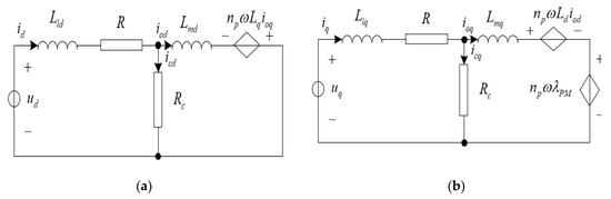
Figure 1.
Dynamic d–q axes equivalent circuits of a PMSM. (a) d axes, (b) q axes.
Similarly, is q axes can be expressed by
The mechanical equation is given by:
The following equation is derived due to the above
Define variable quantities,
where, .
Then, we choose the energy function as follows:
For a surface-mounted PMSM, we have , then model (4) can be converted to a standard Hamiltonian system
where is a skew-symmetric matrix, R(x) is a positive semi-definite matrix, and is the Hamiltonian function. The output is given in the standard form of the Hamiltonian system.
Evaluating the change rate of the Hamiltonian function, we can obtain the following energy balance equation
From Equation (7), we have
When the EV works in a steady state, the electromagnetic torque of the driving motor is equal to the load torque , and the energy balance equation has an equilibrium point, the left side of Equation (9) equals to zero, hence the loss model of the PMSM can be written as
where Ploss is the power loss of the PMSM.
When ignoring the mechanical and stray loss, the efficiency of the PMSM can be expressed as follow
In this paper, we suppose the PMSM works in a steady state, and denote the steady-state current values. Therefore, we can obtain a loss model in a steady state as follows:
3. Efficiency Optimization Strategy
Suppose that , where, is the ratio of direct and quadrature axes excitation current components, then, from Equation (4), we can conclude that
Then, the motor’s steady currents can be expressed by speed, resistances, magnetic flux and the ratio as follows
Substituting (15) into the loss model (13), we have
If Equation (16) reaches its minimum, it implies that .
Differentiating the loss expression (16) with respect to , yields:
From (17), we can conclude that
This result implies that the motor losses reach a minimum when the ratio of excitation current components of the direct axes and quadrature axes satisfies the Equation (18), and is not only related to the parameters of the motor itself, but also to the speed and torque of the motor when it works.
4. Algorithm Realization
According to the above calculation, an energy optimal controller can be designed when the PMSM system runs at a steady state. In order to stabilize the PMSM system in electric vehicle at the minimum loss equilibrium point, a closed-loop expected energy function can be constructed as follows:
By the feedback control, the energy of the original motor system is shaped energy on , and the original system (4) can be written as
where is the interconnection matrix of a closed-loop system, which is a skew-symmetric matrix, and is a positive semidefinite matrix for the closed-loop system. Hence, we can suppose:
And from Equations (7) and (20), we have
Substituting and into (22) we can obtain,
where, are adjustable parameters, which can ensure that is a positive semidefinite matrix.
5. Simulation Results
The efficiency optimization strategy control scheme presented in the previous sections was implemented using Matlab 2019. The main characteristics of the PMSM are listed in Table 2.
Table 2.
Parameters of the PMSM.
The simulations are carried out in the following three conditions:
(1) one condition is that the PMSM runs at a constant speed (with rad/s) and torque (with N·m). This condition shows the control algorithm, where the Hamilton control strategy is employed.
The simulation results are shown in Figure 2a–d. Figure 2a–c shows the direct-axis and quadrature-axis currents, the excitation currents, and the iron loss currents respectively. Notice that the currents can reach the expected values quickly within 0.2 s. Figure 2d shows the rotor speeds with varying parameters (with , , ). The rotor speed is an asymptotic convergence to the expected value. Meanwhile, we can see that the greater the value of r1 and r2, the faster the speed of convergence.
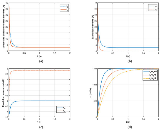
Figure 2.
The simulation results: (a) the direct-axis and quadrature-axis currents ( rad/s, N·m); (b) the excitation currents ( rad/s, N·m); (c) the excitation currents ( rad/s, N·m); (d) the rotor speeds with (, , ).
(2) The second condition is that the PMSM runs at varying speed and a constant Torque ( N·m), and in the constant torque region, the maximum speed is 4000 rad/s. In this condition, we made some comparisons of the following three algorithms: the proposed LMA, the conventional LMA and the control algorithm. The simulation results are shown in Figure 3. Figure 3a reports the different ratio K variations as a function of the rotor speed with the three algorithms at the rated torque of 5 N·m. As seen from Figure 3a, the relationship between parameter K and motor loss is nonlinear. Figure 3b plots the efficiency variations in the above case. Apparently, the proposed control scheme has the highest efficiency.
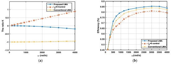
Figure 3.
The simulation results: (a) Comparison of the ratio K of rated torque ( N·m) versus the rotor speed with the three algorithms; (b) Comparison of the motor efficiencies at rated load ( N·m) versus the angular speed.
(3) The last condition is that the PMSM runs at a constant speed ( rad/s) and varies torque, and in the constant speed region, the maximum torque is N·m. The simulation results are shown in Figure 4. Figure 4a shows the ratio K variations as a function of the mechanical load torque at the rated speed ( rad/s) with the three algorithms. Figure 4b presents the efficiency variations. Figure 4b indicates that the effectiveness of the proposed LMA grows with increasing load, and the proposed control scheme has the highest efficiency compared with the other two algorithms.
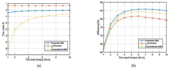
Figure 4.
The simulation results: (a) Comparison of the ratio K at rated rotor speed ( rad/s) versus the load torque; (b) Comparison of the efficiency at rated rotor speed ( rad/s) versus the load torque.
Figure 5 shows the percentage efficiency improvement of the proposed LMA compared with the conventional LMA and the control algorithm. The red dotted curve is the percentage efficiency improvement compared with control algorithm, and the star blue curve is compared with the conventional LMA, and the continuous lines are the fitted curves. These figures indicate that a significant efficiency improvement is reached at high speed, high load as expected. Figure 5a shows the percentage efficiency improvements study as a function of the rotor speed, at a rated load torque ( N·m). These results prove the good performance of the proposed LMA for a low speed range up to high speed. Figure 5b shows the percentage efficiency improvements variation as a function of the mechanical load torque at the rated speed ( rad/s). By inspection of Figure 5b it is possible to realize that the effectiveness of the proposed LMA grows with increasing load.
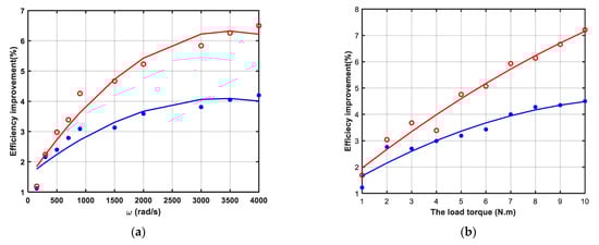
Figure 5.
The simulation results: (a) Efficiency improvement of the proposed LMA at rated load torque ( N·m) versus the rotor speed; (b) Efficiency improvement of the proposed LMA at rated rotor speed ( rad/s) versus the load torque.
In order to illustrate the effectiveness of the proposed algorithm more clearly, the efficiency improvement percentage is measured compared to the other two algorithms under different working conditions, the results are shown in the tables below:
Table 3 shows the percentage efficiency improvements of the proposed LMA with respect to the conventional control and the proposed LMA with respect to the control algorithm , at a rated load torque ( N·m). The efficiency increase is up to 6.26% compared with the control algorithm, and 4.05% compared with the conventional LMA. These results prove the good performance of the proposed LMA for a low speed range up to high speed. Table 4 shows the percentage efficiency improvements at the rated speed ( rad/s). By inspection of Table 2 it is possible to realize that the efficiency increase reaches about 7.12% compared with the control algorithm, and about 4.49% compared with the conventional LMA. A significant efficiency improvement is reached at high load and at high speed, as expected.
Table 3.
Efficiency improvement percentage under various load torques.
Table 4.
Efficiency improvement percentage under various speeds.
6. Conclusions
A new efficiency optimization strategy of a PMSM propelling electric vehicles has been presented in this paper. A PCH model for the PMSM driving system, taking into account iron loss, has been established. Based on the energy balance equation of the PCH model by adjusting the ratio of the excitation current in the d–q axis, the proposed LMA is developed. The optimal controller is achieved by the principle of the energy shape method of the PCH system. Simulation results in different operating conditions verify the effectiveness of the proposed LMA. Compared to the conventional LMA and the control algorithm, the efficiency of the PMSM with the proposed LMA has been improved by about 4% and 7%, respectively, which is well matched to electric vehicle systems running in complicated and changeable circumstances. Thus, the main contribution of this study lies in offering an energy-based efficiency optimization strategy for the PMSM of an electric vehicle. When the electric vehicle runs smoothly, the driving motor works in a steady state, since the energy balance equation is just the power loss of the PMSM, which is very convenient, in that it allows using the energy method for efficiency optimization. Furthermore, it provides a more fundamental understanding of PCH theory. It should be pointed out that this article supposes that motor parameters are constants. In fact, some motor parameters, such as resistance and inductance vary with temperature. In the future, we will study the efficiency optimization strategy of a PMSM with time-varying parameters. In order to further illustrate the effectiveness of our method, the actual experimental verification is also the keynote of our future work.
Author Contributions
Conceptualization, W.P. and Q.Z.; Data curation, W.P.; Formal analysis, W.P., Q.Z. and Y.L.; Funding acquisition, W.P. and Q.Z.; Investigation, W.P., Q.Z. and Y.L.; Methodology, Y.L.; Project administration, W.P., Q.Z. and Y.L.; Resources, Y.L.; Software, W.P. and Q.Z.; Supervision, W.P., Q.Z. and Y.L.; Validation, W.P., Q.Z. and Y.L.; Visualization, W.P., Q.Z. and Y.L.; Writing—original draft, W.P., Q.Z. and Y.L.; Writing—review & editing, W.P. and Q.Z. All authors have read and agreed to the published version of the manuscript.
Funding
This research was funded by National Natural Science Foundation of China, grant number 61803230; Projects of Shandong Province Higher Educational Science and Technology Program, grant number J18KA348, J18KA330 and J18KB144; University outstanding youth innovation team development plan of Shandong Province, grant number 2019KJN023; Key R & D project of Shandong Province, grant number 2019GSF109076, and Shandong Provincial Natural Science Foundation No. ZR2020QF059.
Institutional Review Board Statement
Not applicable.
Informed Consent Statement
Not applicable.
Data Availability Statement
The data in the paper can be requested by email to the corresponding.
Conflicts of Interest
The authors declare no conflict of interest.
References
- Zhang, W.; Wang, Z.; Drugge, L.; Nybacka, M. Evaluating Model Predictive Path Following and Yaw Stability Controllers for Over-Actuated Autonomous Electric Vehicles. IEEE Trans. Veh. Technol. 2020, 69, 12807–12821. [Google Scholar] [CrossRef]
- Chau, K.T.; Chan, C.C.; Liu, C. Overview of Permanent-Magnet Brushless Drives for Electric and Hybrid Electric Vehicles. IEEE Trans. Ind. Electron. 2008, 55, 2246–2257. [Google Scholar] [CrossRef] [Green Version]
- Rezaei, A.; Burl, J.B.; Rezaei, M.; Zhou, B. Catch Energy Saving Opportunity in Charge-Depletion Mode, a Real-Time Controller for Plug-In Hybrid Electric Vehicles. IEEE Trans. Veh. Technol. 2018, 67, 11234–11237. [Google Scholar] [CrossRef]
- Xu, L.; Li, J.; Ouyang, M. Multi-mode control strategy for fuel cell electric vehicles regarding fuel economy and durability. Int. J. Hydrog. Energy 2014, 39, 2374–2389. [Google Scholar] [CrossRef]
- Emadi, A.; Lee, Y.J.; Rajashekara, K. Power electronics and motor drives in electric, hybrid electric, and plug-in hybrid electric vehicles. IEEE Trans. Ind. Electron. 2008, 55, 2237–2245. [Google Scholar] [CrossRef]
- Haddoun, A.; Mohamed, B.H.E.; Demba, D.; Rachid, A.; Jamel, G.; Kamel, S. A Loss-Minimization DTC Scheme for EV Induction Motors. IEEE Trans. Veh. Technol. 2007, 56, 81–88. [Google Scholar] [CrossRef] [Green Version]
- Uddin, M.; Rebeiro, R. Comparison of Efficiency for a PI and a FLC Based IPMSM Drive Incorporating Loss Minimization Algorithm over Wide Speed Range; Energy Conversion Congress & Expositions: San Jose, CA, USA, 2009. [Google Scholar]
- Zhu, Z.Q.; Howe, D. Electrical machines and drives for electric, hybrid, and fuel cell vehicles. Proc. IEEE 2007, 95, 746–765. [Google Scholar] [CrossRef]
- Rubino, S.; Dordevic, O.; Bojoi, R.; Levi, E. Modular Vector Control of Multi-Three-Phase Permanent Magnet Synchronous Motors. IEEE Trans. Ind. Electron. 2021, 68, 9136–9147. [Google Scholar] [CrossRef]
- Boldea, I.; Tutelea, L.; Parsa, L.; Dorrell, D. Automotive electric propulsion systems with reduced or no permanent magnets: An overview. IEEE Trans. Ind. Electron. 2014, 61, 5696–5711. [Google Scholar] [CrossRef]
- Morimoto, S.; Ooi, S.; Inoue, Y.; Sanada, M. Experimental evaluation of a rare-earth-free PMSM with ferrite magnets for automotive applications. IEEE Trans. Ind. Electron. 2014, 61, 5749–5756. [Google Scholar] [CrossRef]
- Hu, X.; Jiang, J.; Egardt, B.; Cao, D. Advanced power-source integration in hybrid electric vehicles: Multicriteria optimization approach. IEEE Trans. Ind. Electron. 2015, 62, 7847–7858. [Google Scholar] [CrossRef]
- Carpiuc, S.-C. Rotor temperature detection in permanent magnet synchronous machine-based automotive electric traction drives. IEEE Trans. Power Electron. 2017, 32, 2090–2097. [Google Scholar] [CrossRef]
- Mun, J.-M.; Park, G.-J.; Seo, S.; Kim, D.-W.; Kim, Y.-J.; Jung, S.-Y. Design characteristics of IPMSM with wide constant power speed range for EV traction. IEEE Trans. Magn. 2017, 53, 1–4. [Google Scholar] [CrossRef]
- Lim, M.-S.; Chai, S.-H.; Hong, J.-P. Design of saliency-based sensorless-controlled IPMSM with concentrated winding for EV traction. IEEE Trans. Magn. 2016, 52, 8200504-1–8200504-4. [Google Scholar] [CrossRef]
- Liu, T.; Hu, X.; Li, S.E.; Cao, D. Reinforcement learning optimized look-ahead energy management of a parallel hybrid electric vehicle. IEEE/ASME Trans. Mechatron. 2017, 22, 1497–1507. [Google Scholar] [CrossRef]
- Wei, D.; He, H.; Cao, J. Hybrid electric vehicle electric motors for optimum energy efficiency: A computationally efficient design. Energy 2020, 203, 117779. [Google Scholar] [CrossRef]
- Malekpour, M.; Abarghooee, R.; Terzija, V. Maximum torque per ampere control with direct voltage control for IPMSM drive systems. Int. J. Electr. Power Energy Syst. 2020, 116, 105509. [Google Scholar] [CrossRef]
- Vaez, S. Loss Minimization Control of Interior Permanent Magnet Motor Drives. Ph.D. Dissertation, Queen’s University at Kingston, Kingston, ON, Canada, 1997. [Google Scholar]
- Bose, B.K. A high-performance inverter-fed drive system of an interior permanent magnet synchronous machine. IEEE Trans. Ind. Appl. 1988, 24, 987–997. [Google Scholar] [CrossRef]
- Morimoto, S.; Sanada, M.; Takeda, Y. Wide-speed operation of interior permanent magnet synchronous motors with high-performance current regulato. IEEE Trans. Ind. Appl. 1994, 30, 920–926. [Google Scholar] [CrossRef]
- Lenke, R.U.; Doncker, R.W.D.; Mu-Shin, K. Field weakening control of interior permanent magnet machine using improved current interpolation technique. In Proceedings of the 37th IEEE Power Electronics Specialists Conference, Jeju, Korea, 18–22 June 2016; pp. 1–5. [Google Scholar]
- Kim, J.M.; Sul, S.K. Speed control of interior permanent magnet synchronous motor drive for the flux weakening operation. IEEE Trans. Ind. Appl. 1997, 33, 43–48. [Google Scholar]
- Pan, C.T.; Liaw, J.H. A robust field-weakening control strategy for surface-mounted permanent-magnet motor drives. IEEE Trans. Energy Convers. 2005, 20, 701–709. [Google Scholar] [CrossRef]
- Cheng, N.; Zhang, Y.; Gui, W. Flux weakening control of embedded permanent magnet synchronous motor drive system. Control. Theory Appl. 2013, 28, 717–723. [Google Scholar]
- Bai, Y.; Tang, X.; Wu, G. Flux-weakening speed control of the Interior permanent magnet synchronous motor. Trans. China Electro Tech. Soc. 2011, 26, 54–59. [Google Scholar]
- Cavallaro, C.; Di Tommaso, A.O.; Miceli, R.; Raciti, A.; Galluzzo, G.R.; Trapanese, M. Efficiency enhancement of permanent-magnet synchronous motor drives by online loss minimization approaches. IEEE Trans. Ind. Electron. 2005, 52, 1153–1160. [Google Scholar] [CrossRef] [Green Version]
- Guo, Q.; Zhang, C.; Li, L.; Zhang, J.; Liu, J.; Wang, T. Efficiency optimization control of permanent magnet synchronous motor for electric vehicle. Micromotors 2014, 47, 142–146. [Google Scholar]
- Morimoto, S.; Tong, Y.; Takeda, Y.; Hirasa, T. Loss minimization control of permanent magnet synchronous motor drives. IEEE Trans. Ind. Electron. 2002, 41, 511–517. [Google Scholar] [CrossRef]
- Hang, J.; Wu, H.; Ding, S.; Huang, Y.; Wei, H. Improved Loss Minimization Control for IPMSM Using Equivalent Conversion Method. IEEE Trans. Power Electron. 2021, 36, 1931–1940. [Google Scholar] [CrossRef]
- Pei, W.; Li, C.Z.K.; Cui, N. Hamilton system modeling and passive control for induction motor of electric vehicles by considering iron losses. Control. Theory Appl. 2011, 28, 869–873. [Google Scholar]
- Gonz’alez, H. Development of Control Schemes Based on Energy Shaping for a Class of Nonlinear Systems and Design of a Triphase Inverter Open Prototype for Online Applications in Induction Motors; University of Chile: Santiago, Chile, 2005. (In Spanish) [Google Scholar]
- Yu, J.; Pei, W.; Zhang, C. A Loss-Minimization Port-Controlled Hamilton Scheme of Induction Motor for Electric Vehicles. IEEE/ASME Trans. Mechatron. 2015, 20, 2645–2653. [Google Scholar] [CrossRef]
- Batlle, C.; Cerezo, A.D. Energy based modelling and simulation of the interconnection of a back-to-back converter and a doubly-fed induction machine. In Proceedings of the 2006 American Control Conference Minneapolis, Minneapolis, MN, USA, 14 June 2016; pp. 1851–1856. [Google Scholar]
Publisher’s Note: MDPI stays neutral with regard to jurisdictional claims in published maps and institutional affiliations. |
© 2022 by the authors. Licensee MDPI, Basel, Switzerland. This article is an open access article distributed under the terms and conditions of the Creative Commons Attribution (CC BY) license (https://creativecommons.org/licenses/by/4.0/).