1. Introduction
Articulated wagons are used to increase the volume of freights transported by rail. A feature of such wagons is that their design consists of two sections, which are supported on three bogies. The sections interact with each other through an articulated coupling.
At present, flat wagons are the most widespread among such wagons. The variety of articulated wagons is very large [
1], which is due to a number of advantages over other types:
Savings in manufacturing costs;
Reduction of vertical loading on a frame;
Savings in cargo transportation, especially for long-haul traffic;
Reduction of required wagon fleet;
Decrease in the cost of the wagon life cycle, etc.
The main distinguishing features of articulated wagons are their design, method of loading, types of bogies, articulated coupling, etc. The articulated parts of the frame and the wagon are symmetrical about the center bogie axis.
To increase the volume of transportation of goods requiring protection from atmospheric precipitation, it is necessary to create innovative articulated covered wagon designs. Such a technical solution will reduce the wagon manufacturing cost at the design stage, as well as increase the efficiency of railway transport operation (reduction of maintenance and repair costs).
In this context, it is urgent to undertake research on the creation of an algorithm for the design and calculation of articulated wagons using technical solutions that are non-trivial for car building while meeting the strength and operational reliability conditions.
Mathematical simulation of the interaction between a railway wagon and rails has been carried out in a previous study [
2]. The motion equations were compiled by linking the linear and nonlinear dynamic characteristics of the system. The equilibrium method was used to derive the load vectors. The results were confirmed by experimental studies.
It is important to note that attention was not paid to the determination of the longitudinal loading of articulated wagons under operational loading conditions in this work.
The basic requirements for the supporting structures of modern rolling stock are described in [
3]. These requirements are applicable for modernized rolling stock, as well as for the designed rolling stock in the conditions of car-building facilities.
However, this study did not present the requirements applicable for articulated wagons.
The determination of the wagon dynamic loading under operational loading conditions was carried out in [
4]. The calculation was carried out for the most unfavorable conditions, namely a shunting collision.
Studies of vehicle dynamic loading have been carried out in [
5,
6,
7]. The mathematical models were confirmed by computer simulations.
However, an examination of the longitudinal dynamics of articulated wagons was not conducted in the study.
The procedure for designing and manufacturing a scalable railway wagon was described in [
8]. In this case, modern software tools were used. The structural concepts used in the wagon’s design ensured compliance with dynamic indexes when interacting with the rail track within the acceptable range.
Measures to improve the stability of the rolling stock under operational loading conditions are given in [
9]. The research results were confirmed by experimental data.
However, this study did not pay attention to the articulated wagon dynamics.
The determination of wagon shock-loading was carried out in [
10]. In the quality of the studied parameter, accelerations were considered as dynamic loading components.
The calculation of the dynamic characteristics of freight wagons with various bogies is provided in [
11]. It was found that the indicators of movement dynamic qualities were almost the same when using the designs of freight wagon bogies under consideration.
The determination of the dynamic characteristics of articulated wagons was not carried out in this work.
Numerical simulation and experimental studies of the rolling stock structural components strength are described in [
12]. In this case, the normative values of operational loads were taken into account. The results of the theoretical studies were confirmed by the method of electrical strain measurement.
Strength analysis of the articulated wagons’ supporting structures was not carried out in this study.
Features of multi-objective crashworthiness optimization are described in [
13]. The optimal parameters of the pipes’ cross-sections, ensuring their strength under the influence of shock load, were determined.
It is important to note that the determination of the rolling stock body strength using pipes as bearing elements is not given in the study.
The purpose of the present article is to cover issues in the dynamics and strength analysis of a circular pipe design for an articulated covered wagon. To achieve this goal, the following tasks were defined:
Creation of an articulated covered wagon design, the body-supporting elements of which are made of circular pipes. The model was symmetrical with regard to the longitudinal axis;
Conduction of a mathematical simulation of the dynamic loading of the articulated covered wagon supporting structure;
Conduction of a computer simulation of the dynamic loading of the articulated covered wagon supporting structure;
Checking the adequacy of the developed dynamic loading models of the articulated covered wagon supporting structure;
Carrying out of the strength analysis of the articulated covered wagon supporting structure;
Calculation of the fatigue strength of the articulated covered wagon body-supporting structure and determination of its design life;
Calculation of the strength of the weld in the interaction zone of the center sill and the bolster beam.
2. Materials and Methods
In order to reduce the material consumption of the bearing structure of the covered wagon, it was optimized according to the criterion of minimum material consumption. When doing this, the method of optimization for strength reserves was used. To determine the strength reserves of a typical bearing structure of a covered wagon, a 3D model was built in the SolidWorks Simulation software package (Vélizy-Villacoublay, France). Strength calculation was carried out using the finite element method.
Isoparametric tetrahedrons were taken into account when compiling the finite element model of the covered wagon supporting structure. The optimal number of model elements was determined by the graphical–analytical method. Based on the results of the calculations, the optimal geometric parameters of circular pipes were determined, taking into account the minimum material consumption. It was proposed to manufacture the supporting structure of a covered wagon from the circular pipes. On the basis of the proposed supporting structure for a covered wagon, an articulated wagon was created.
To determine the dynamic loading of the supporting structure of a covered wagon, mathematical simulation was carried out. The calculation was carried out in the MathCad software package. The articulated coupling was simulated by using a rigid connection. The magnitude of the longitudinal force that acts on the wagon bearing structure was assumed to be 2.5 MN [
14,
15]. Bogies 18–100 were used as running gears. Differential equations were solved in MathCad software. The Runge–Kutta method [
16,
17] was used as a calculation method. In order to use the standard function rkfixed in MathCad, a transition was made from second-order equations to first-order equations. The initial velocities and displacements were taken to be equal to zero.
To determine the acceleration fields in relation to the improved supporting structure for a covered wagon, a computer simulation of its dynamic loading was carried out. The calculation was carried out in CosmosWorks software [
18,
19]. This computational software was chosen because it is currently widely used in the calculations of wagon structures. For example, Uralvagonzavod has designed and put into operation a series of tank wagons, which are designed specifically in this software product. The finite element method [
20,
21] was used for the calculation.
While compiling the finite element model, isoparametric tetrahedrons were used. The graphoanalytical method was used to determine the optimal number of model elements. The number of model nodes was 822,453 and the number of elements was 2,487,734. The maximum element size was 35 mm and the minimum one was 7 mm. The percentage of elements with an aspect ratio of less than three was 72.5 and the percentage of elements with an aspect ratio of more than 10 was 1.43. The minimum number of elements in the circle was 22 and the ratio of the increase in the elements size was 1.8.
To test the adequacy of the developed dynamic loading models of the articulated covered wagon bearing structure, the calculation was carried out according to the F-criterion [
22,
23,
24].
A calculation was performed to test the strength of the improved supporting structure of the covered wagon. The finite element method was used as a calculation method, implemented in the SolidWorks Simulation software package.
The developed supporting structure of the articulated covered wagon body was calculated for the fatigue strength. The calculation was carried out with CosmosWorks software. The test base amounted to 10
7 cycles [
25,
26] in this case. The fatigue curve was obtained by dividing each numerical stress value of the reference curve SN by the elasticity modulus of the reference material ASME and then multiplying the obtained value by the elasticity modulus of the current material.
To determine the design service life of the supporting structure of a covered wagon, the method devised by Ustich was used.
To ensure the strength of the supporting structure of the covered wagon in the zones where the individual components interact with each other, the calculation of the welds in the most loaded nodes was carried out.
3. Creation of an Articulated Covered Wagon Design, the Body-Supporting Elements of Which Are Made of Circular Pipes
The use of circular pipes in the covered wagon supporting structure was proposed to reduce its empty weight. We have already carried out work on the introduction of circular pipes as elements of wagon supporting structures. When doing so, the main types of wagons were taken into account: open wagons, flat wagons, covered wagons and hopper wagons. On the basis of the created designs, articulated wagons were proposed and patented. However, in previous publications, open wagons were taken into account. In this regard, in this article, we describe the features involved in creating and calculating the bearing structure of an articulated covered wagon, designed for the hauling of goods requiring protection from atmospheric precipitation.
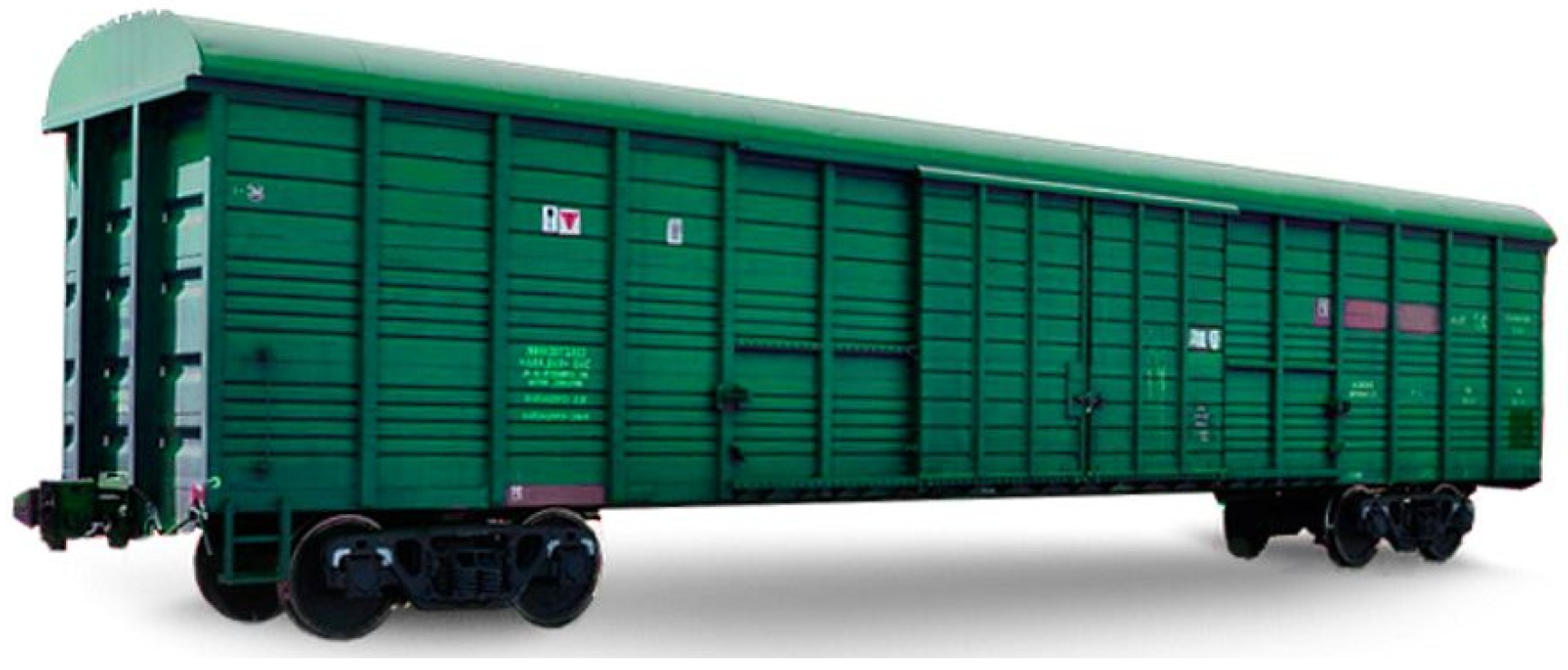
A covered wagon model 11-217 (
Figure 1), built by PJSC Altaivagonzavod (Novoaltaisk, Russia), was considered as a prototype.
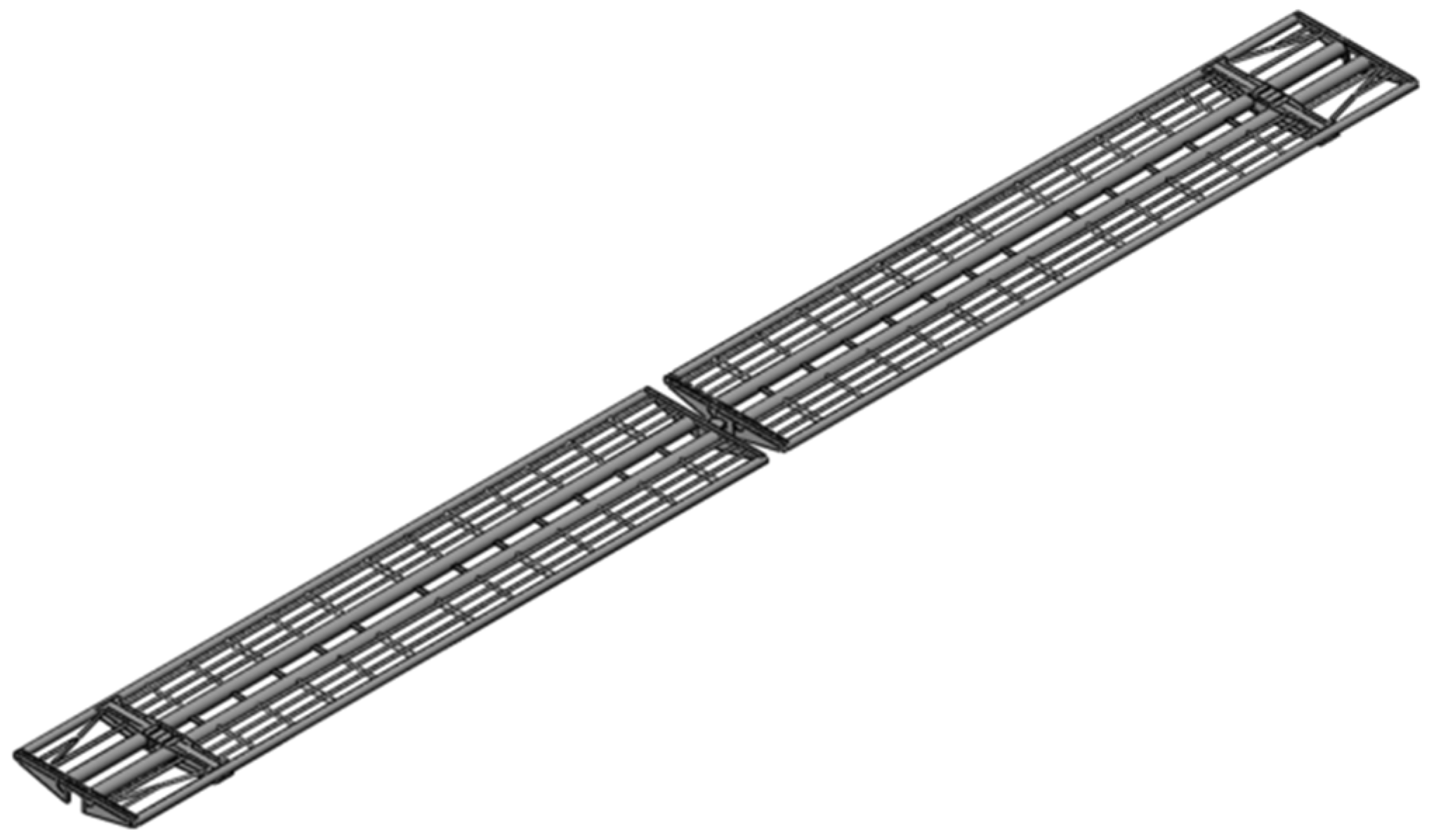
Optimization was carried out on the strength reserves of typical elements of the covered wagon body bearing structure. The spatial model of the covered wagon body made of round pipes is shown in
Figure 2. When creating the model, structural elements that rigidly interact with each other were taken into account.
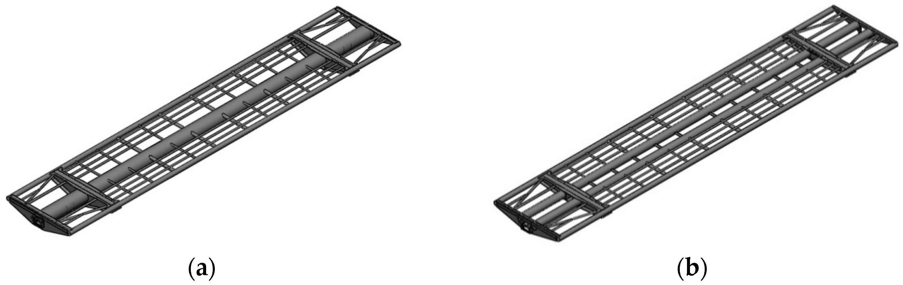
The center sill of such a wagon can be made either of one pipe (
Figure 3a) or two pipes (
Figure 3b). It is possible to see that the created structures are symmetrical to the longitudinal axis.
The proposed technical solution made it possible to reduce the mass of the covered wagon body-supporting structure compared to the prototype wagon by 4% (one pipe) and 4.84% (two pipes). In other words, this wagon design can reduce the manufacturing cost during production in the car-building facilities.
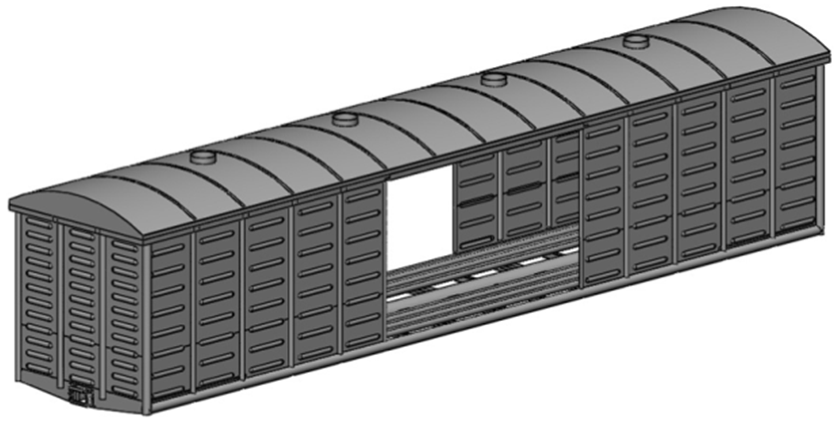
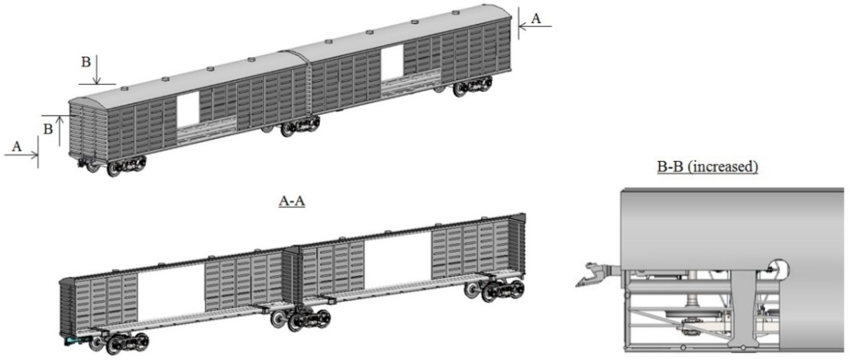
To increase the volume of cargo transportation, an articulated wagon was developed on the basis of the proposed covered wagon design (
Figure 4).
The section frame had a modified design, in contrast to the designs shown in
Figure 3. On the side of the section support on the middle bogie, the bolster beam was replaced by a beam made of a round pipe (
Figure 5).
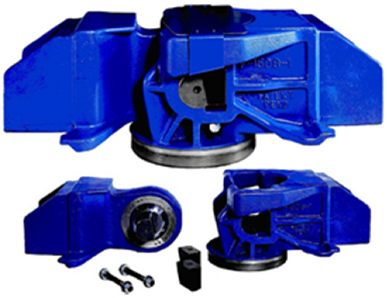
For the interaction between the sections, a typical articulated coupling type SAC-1 was used from the company WABTAC (
Figure 6) [
27,
28].
However, it is possible to use articulated couplings from other manufacturers.
4. Mathematical Simulation of Dynamic Loading of the Articulated Covered Wagon Supporting Structure
To determine the dynamic loading of an articulated covered wagon under one of the most loaded operating conditions—that is, a jerk—a mathematical model was created, which is represented by Equations (1)–(6):
where
;
,
is the gross weight of the
i-th section;
is the weight of the bearing structure of the
i-th section;
is an inertia moment of the
i-th section;
is a value of the longitudinal force acting on the automatic coupling;
is an absolute value of the dry friction force in the coil spring group;
is the stiffness of connection between sections;
are the springs stiffness of the bogies spring groups; and
are coordinates that determine the section movements relative to the corresponding axes.
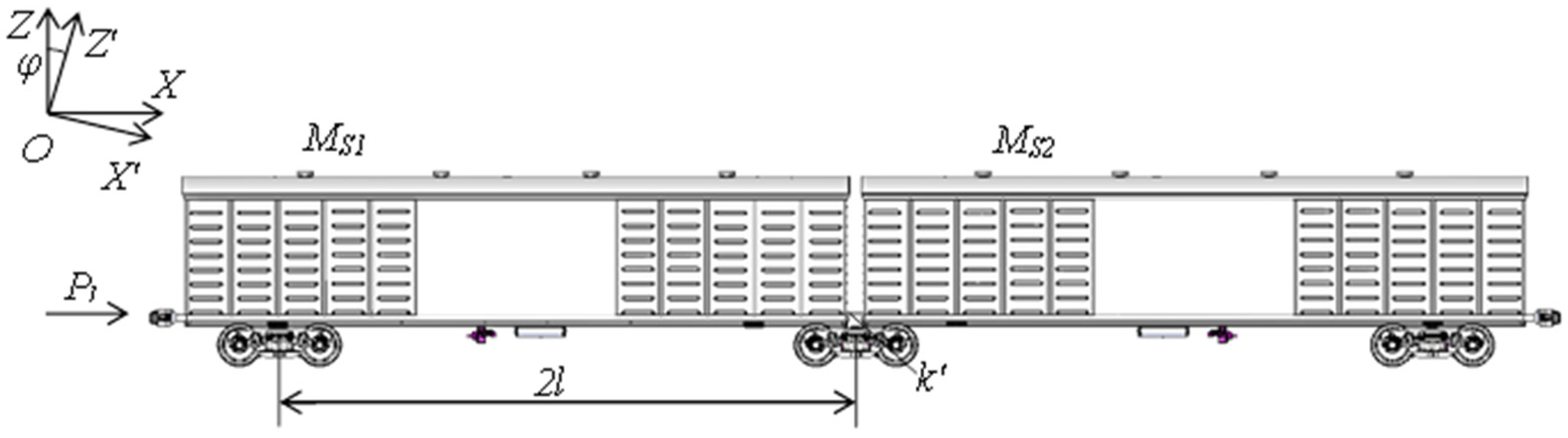
The study of the oscillatory process was carried out in a flat coordinate system. At the same time, it was taken into consideration that the wagon had three degrees of freedom: vibrations of jerking, chattering and pitching [
29]. The design scheme is presented in
Figure 7.
Due to the fact that the wheelsets had an axial load of 23.5 t/axle (230.535 kN/axle), the gross weight of the wagon was intended to not exceed 1383.21 kN. It is also possible to use bogies with increased axial load under such a wagon.
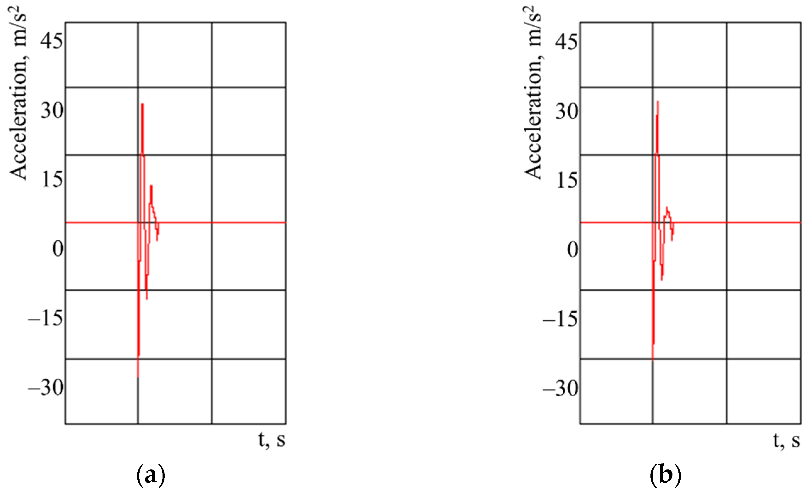
The accelerations acting on the articulated covered wagon are shown in
Figure 8.
The research results made it possible to conclude that the accelerations acting on the bearing structure of the first wagon section from the side of the longitudinal force action were 28.4 m/s², and the accelerations acting on the second wagon section were 27.9 m/s² (
Figure 8).
5. The Dynamic Loading Computer Simulation of the Articulated Covered Wagon Supporting Structure
As the frame is the most loaded wagon unit, its frame calculation is given below for a better visualization of the obtained results.
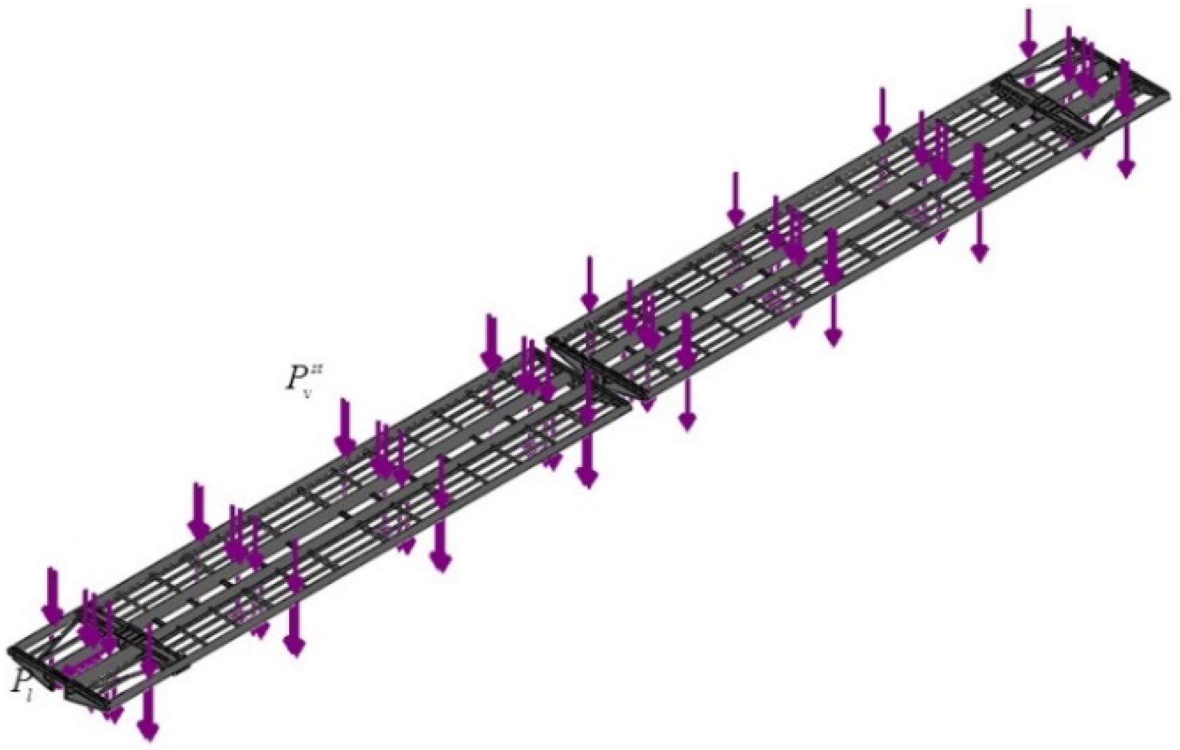
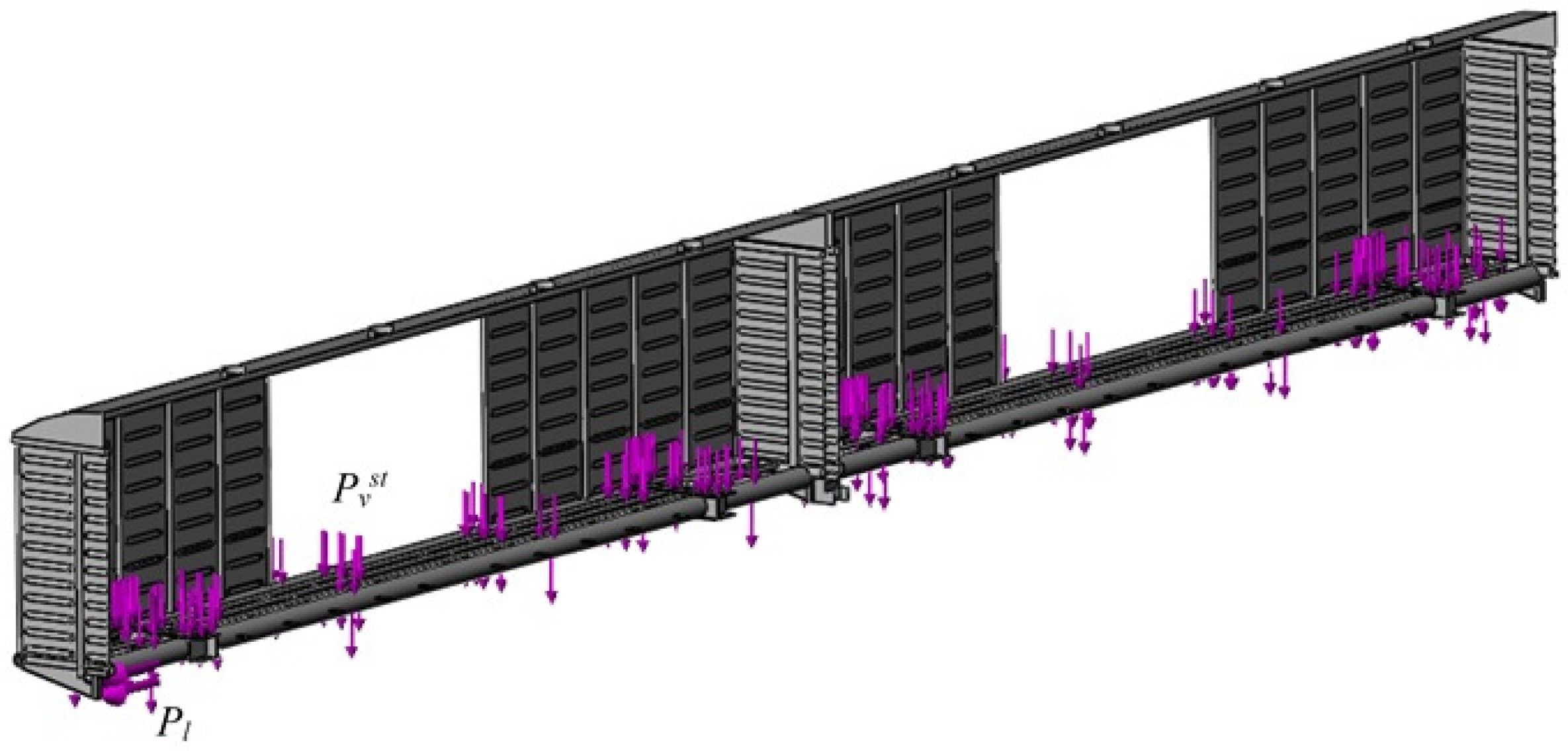
When creating the strength model, it was taken into account that the vertical static load
Pvst, which is caused by the wagon dead weight and by its loading level, acts on the wagon bearing structure (
Figure 9). This load is distributed symmetrically to the longitudinal axis, which is depicted by violet arrows in
Figure 9. It was also taken into account that the longitudinal force
Pl acts on the front coupler horns. It was assumed that the wagon would be loaded with a conditional load using the maximum permissible load capacity. The possible movements of the load in the body were not taken into account for the action of the longitudinal load on the wagon.
The model was fixed in the areas of support on the chassis. The steel 09G2S was used as a construction material.
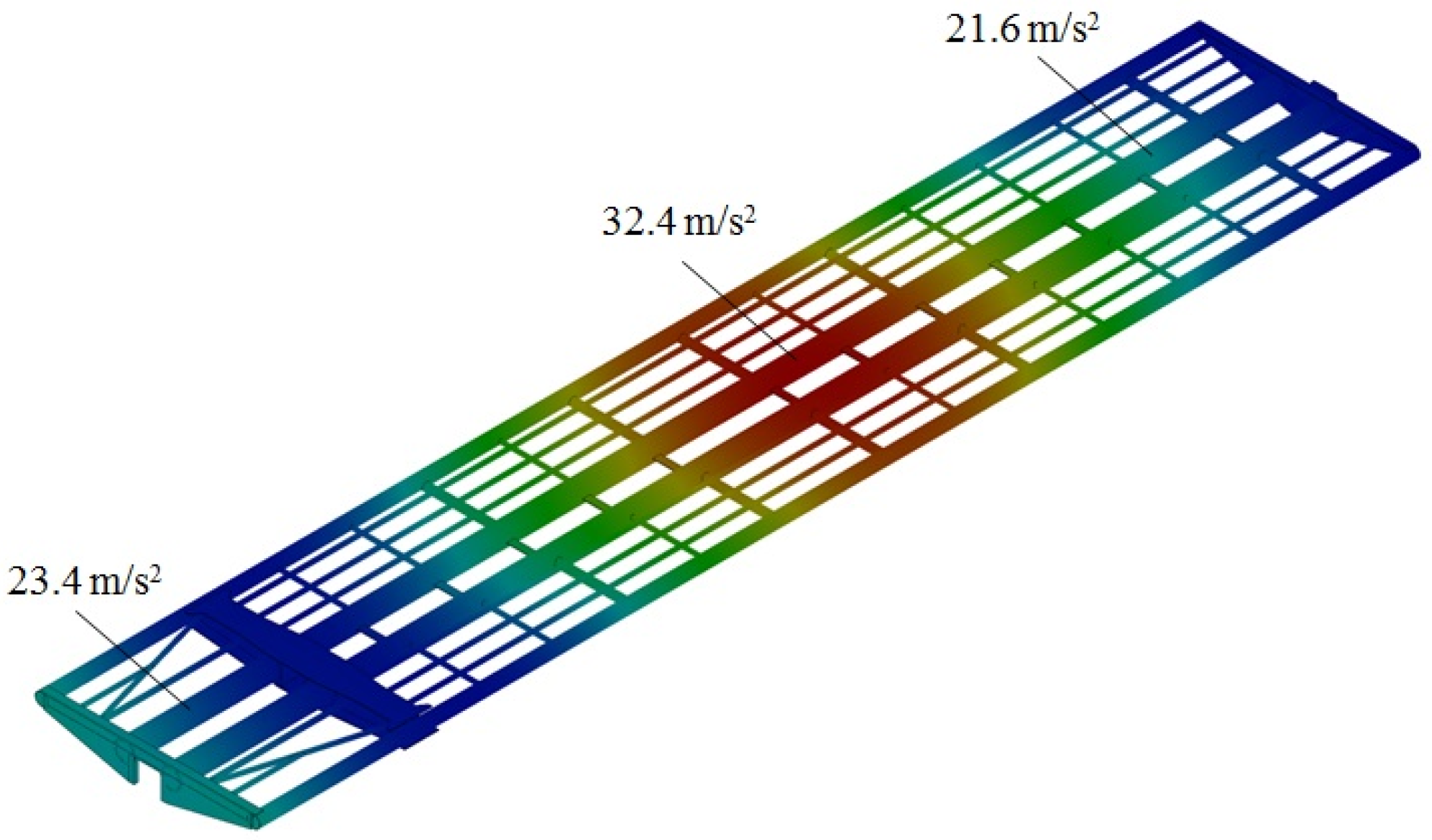
Based on the calculations, it was found that the maximum acceleration acting on the first section from the side of the longitudinal force action was about 32.4 m/s
2, and the maximum acceleration acting on the second section was 31.7 m/s
2 (
Figure 10).
The maximum accelerations were concentrated in the middle parts of the sections. Near the console parts of the sections, the accelerations decreased and amounted to 23.4 m/s2 (first section) and 22.6 m/s2 (second section). It could be observed that the structure was loaded symmetrically to the longitudinal axis.
A modal analysis was carried out to determine the limiting frequencies and vibration modes of the articulated covered wagon frame. The numerical values of the limiting vibration frequencies are given in
Table 1.
The calculations showed that the critical frequencies were within acceptable limits.
6. Validation of the Developed Dynamic Loading Models of the Articulated Covered Wagon Supporting Structure for Adequacy
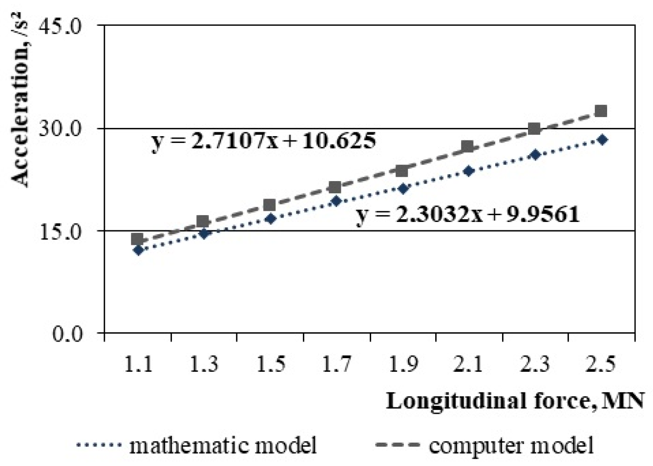
The input parameter of the model was the longitudinal force acting on the front coupler horn, and the output was the acceleration acting on the supporting structure (
Table 2).
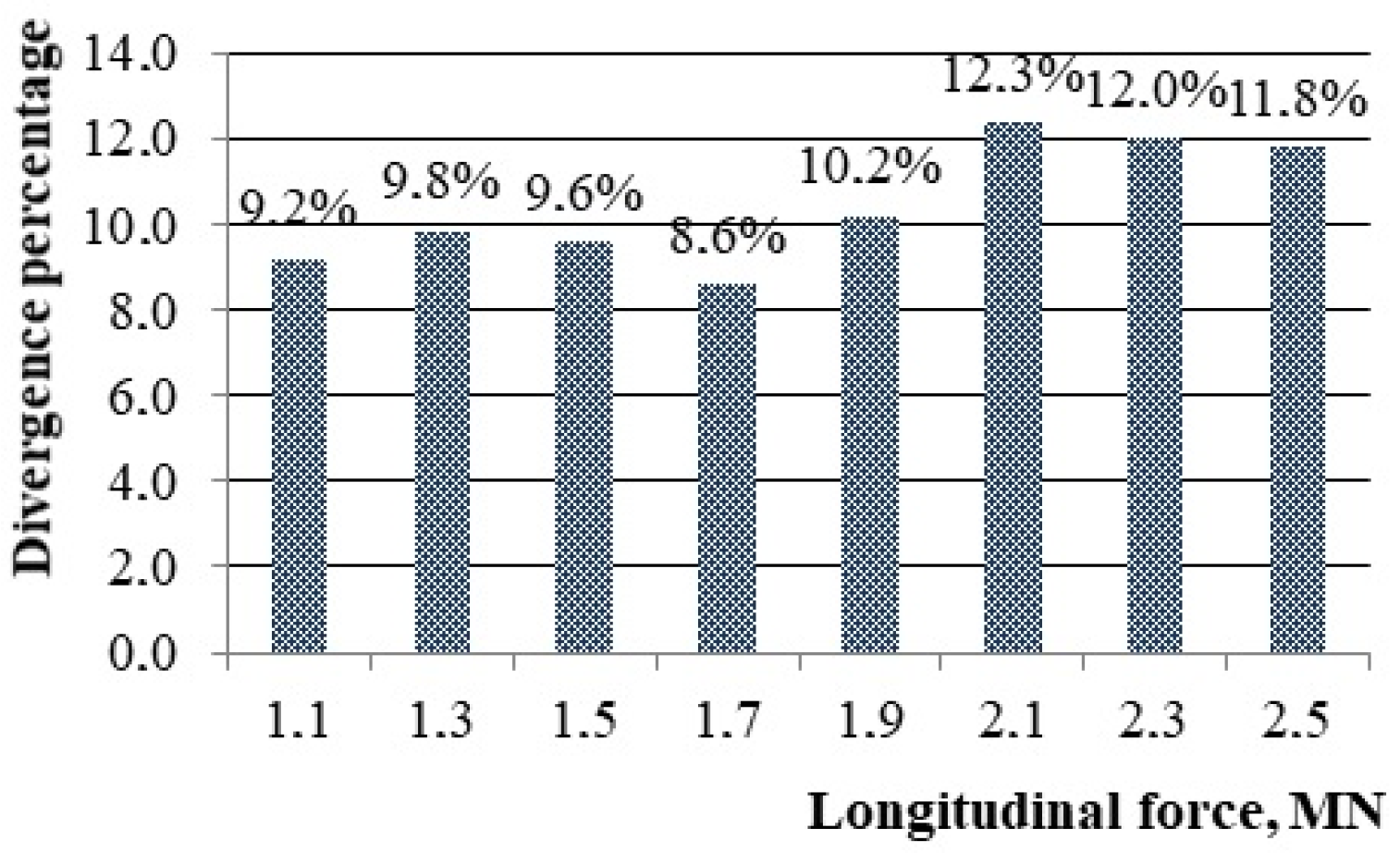
The calculation results are shown in
Figure 11. The percentage difference between the results of the mathematical and computer simulation is shown in
Figure 12. In this case, the maximum divergence was about 12%.
The calculations showed that for the adequacy variance of Sa = 44.2 and the repeatability variance Sr = 31.8, the calculated value of the criterion was Fc = 1.4. Moreover, the tabular value of the criterion was Ft = 3.07. So the hypothesis of adequacy was not rejected.
7. Strength Analysis of an Articulated Covered Wagon Bearing Structure
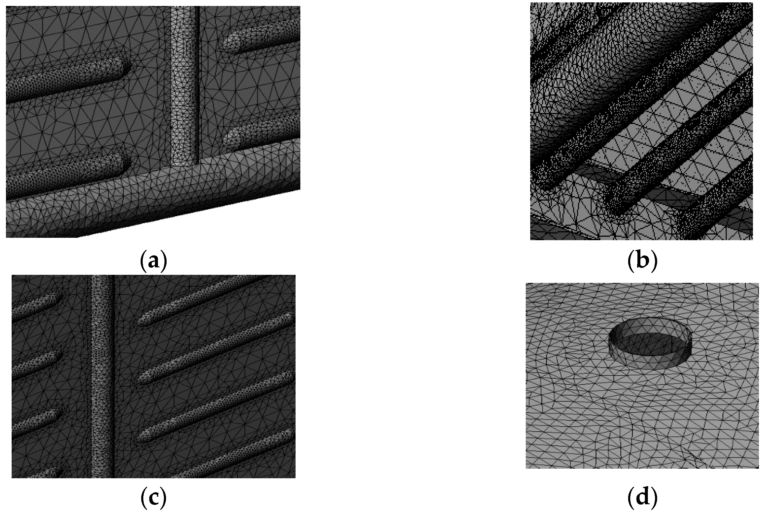
A calculation was performed using the finite element method to determine the strength indexes of the articulated covered wagon bearing structure. Fragments of the finite element model are shown in
Figure 13.
The calculated loads acting on the articulated covered wagon bearing structure were identical to the loads that were taken into account for the study of dynamic loading (
Figure 14).
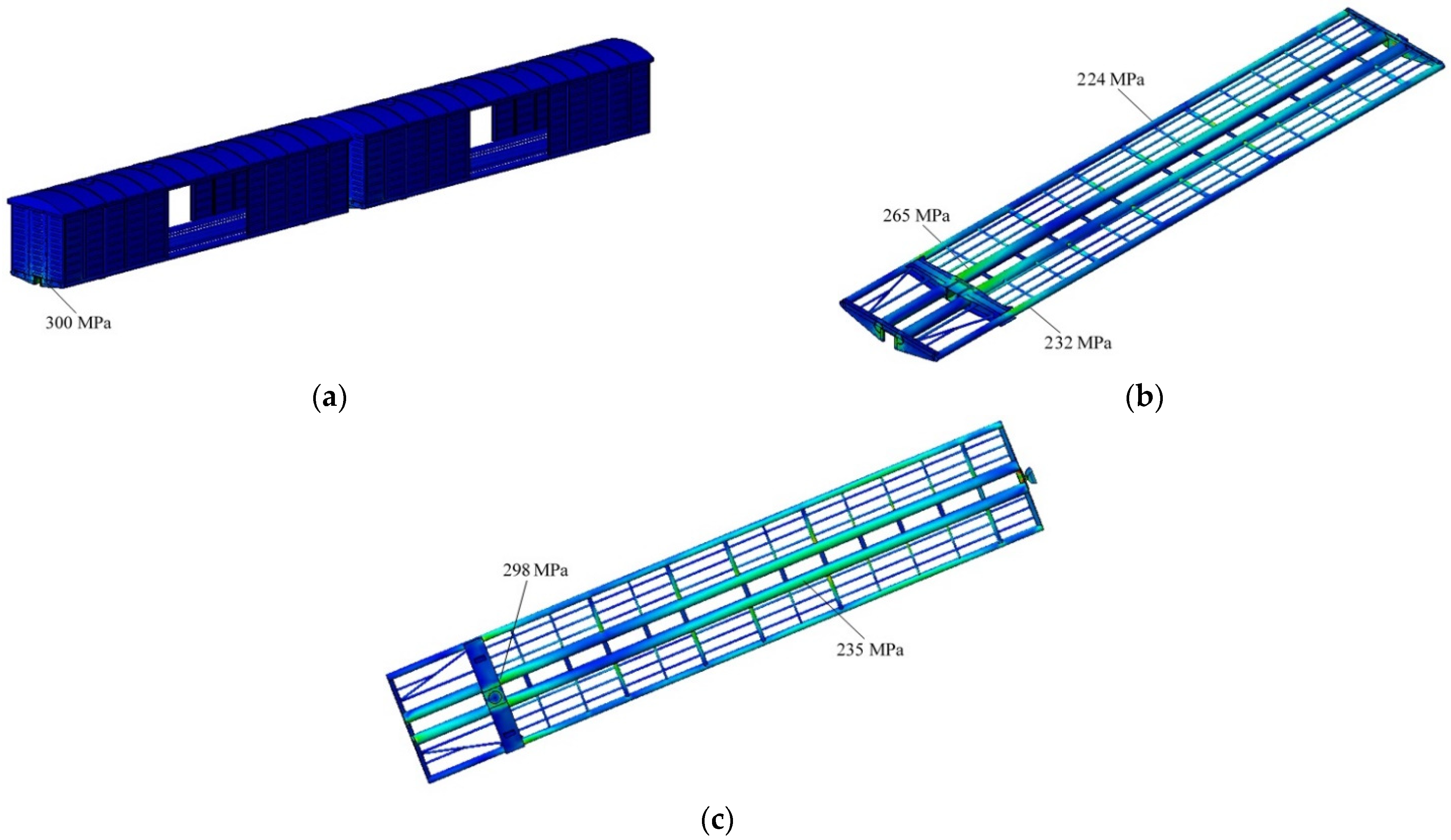
The calculation results are shown in
Figure 15.
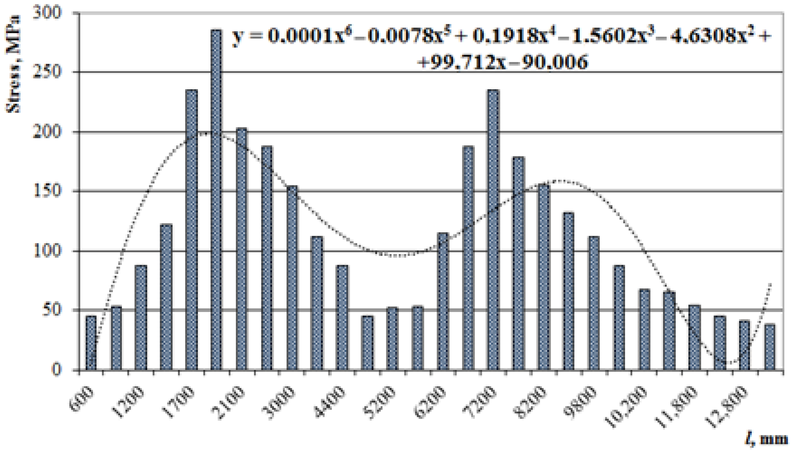
The maximum equivalent stress arose in the zone of interaction between the center sill and the bolster beam and was about 300 MPa; that is, it did not exceed the allowed limits for the steel grade of a metal structure [
14,
15,
25,
26]. The distribution of the maximum equivalent stresses along the length of the center sill of the first wagon section from the side of the longitudinal force action is shown in
Figure 16.
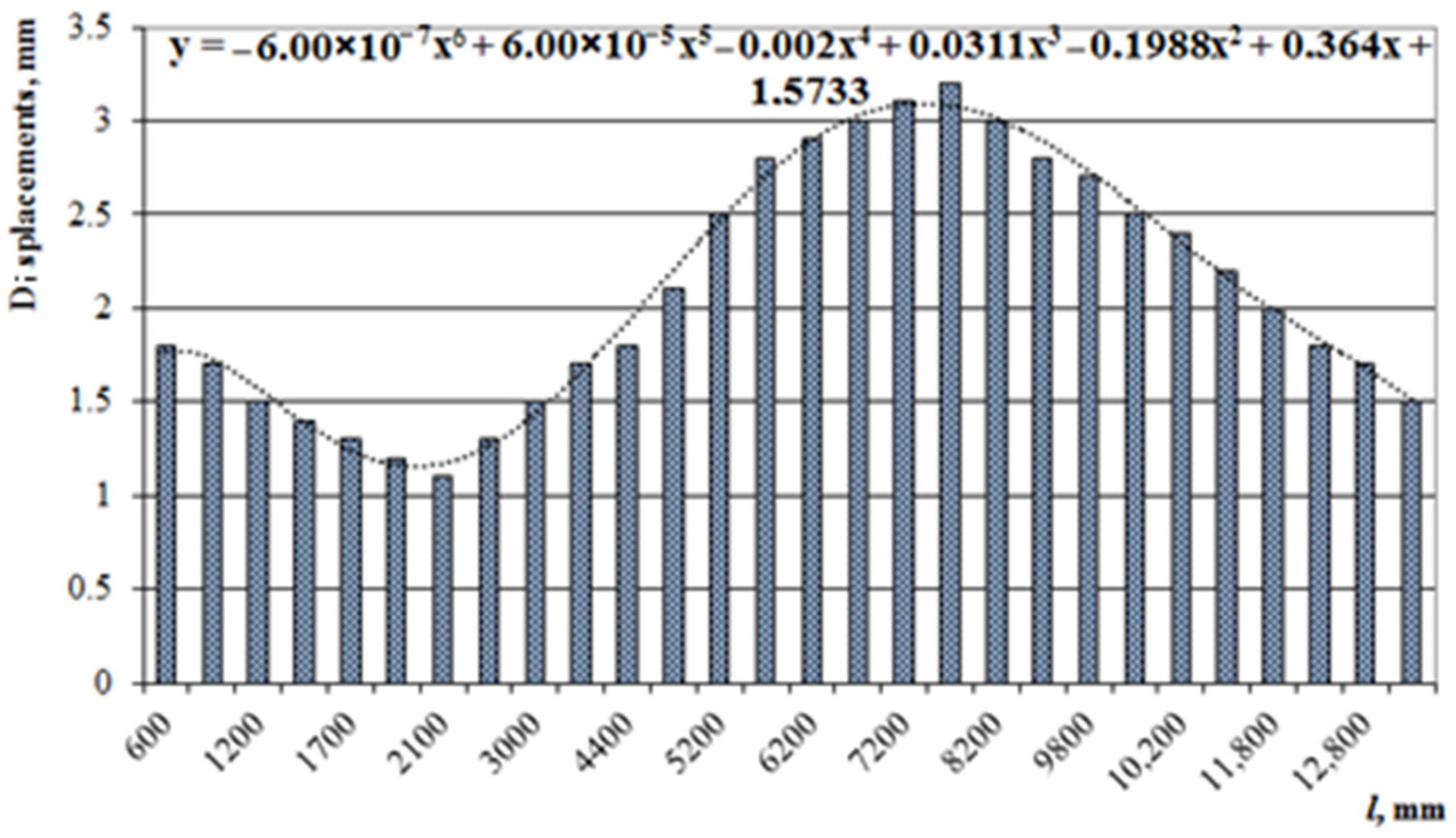
It was thus established that the stress distribution occurred according to the polynomial law.
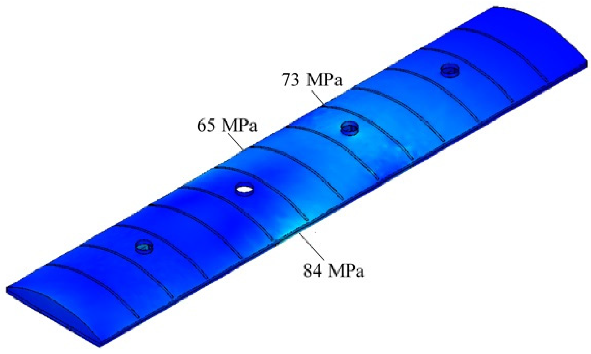
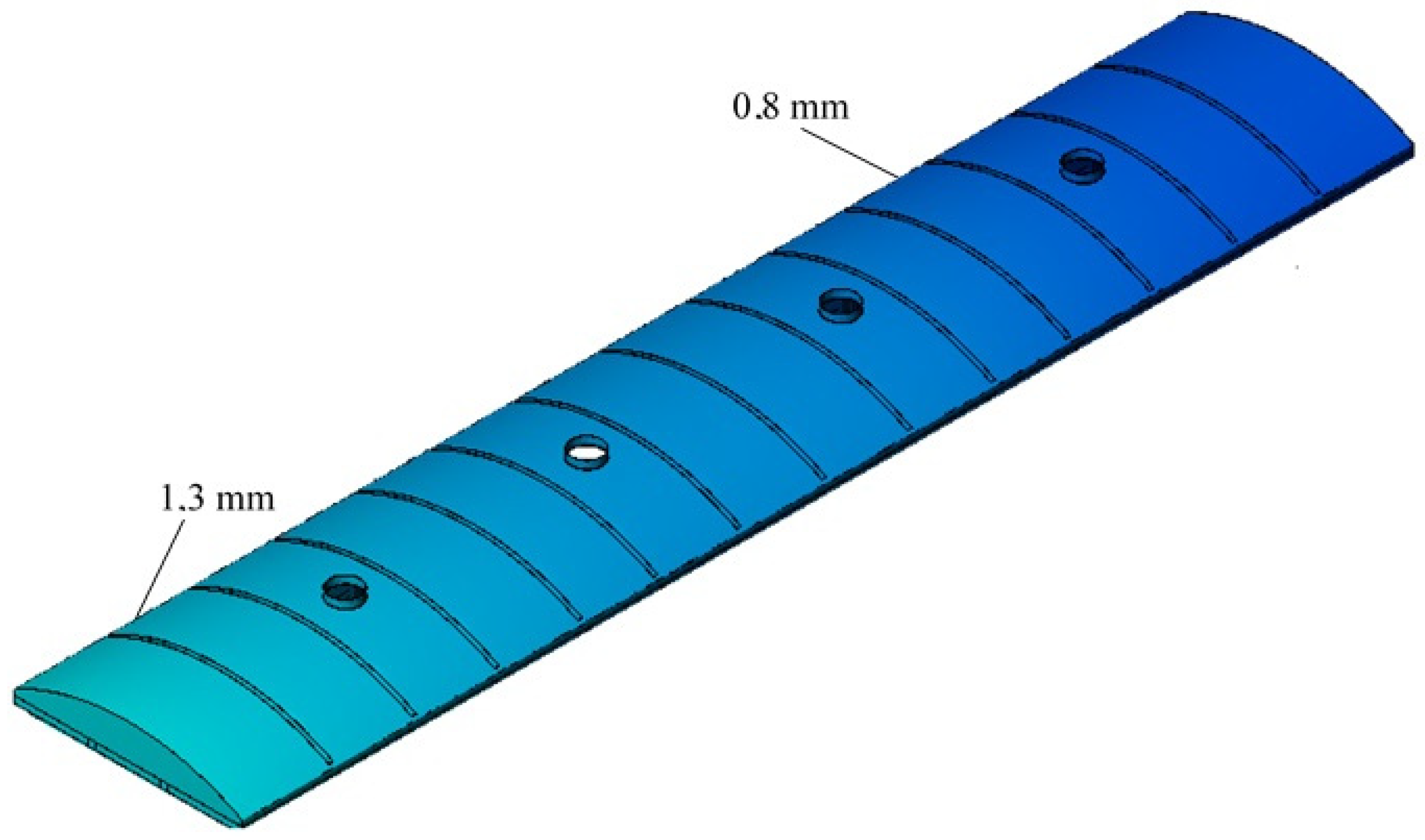
In the roof of the section, the maximum equivalent stresses amounted to 84 MPa (
Figure 17).
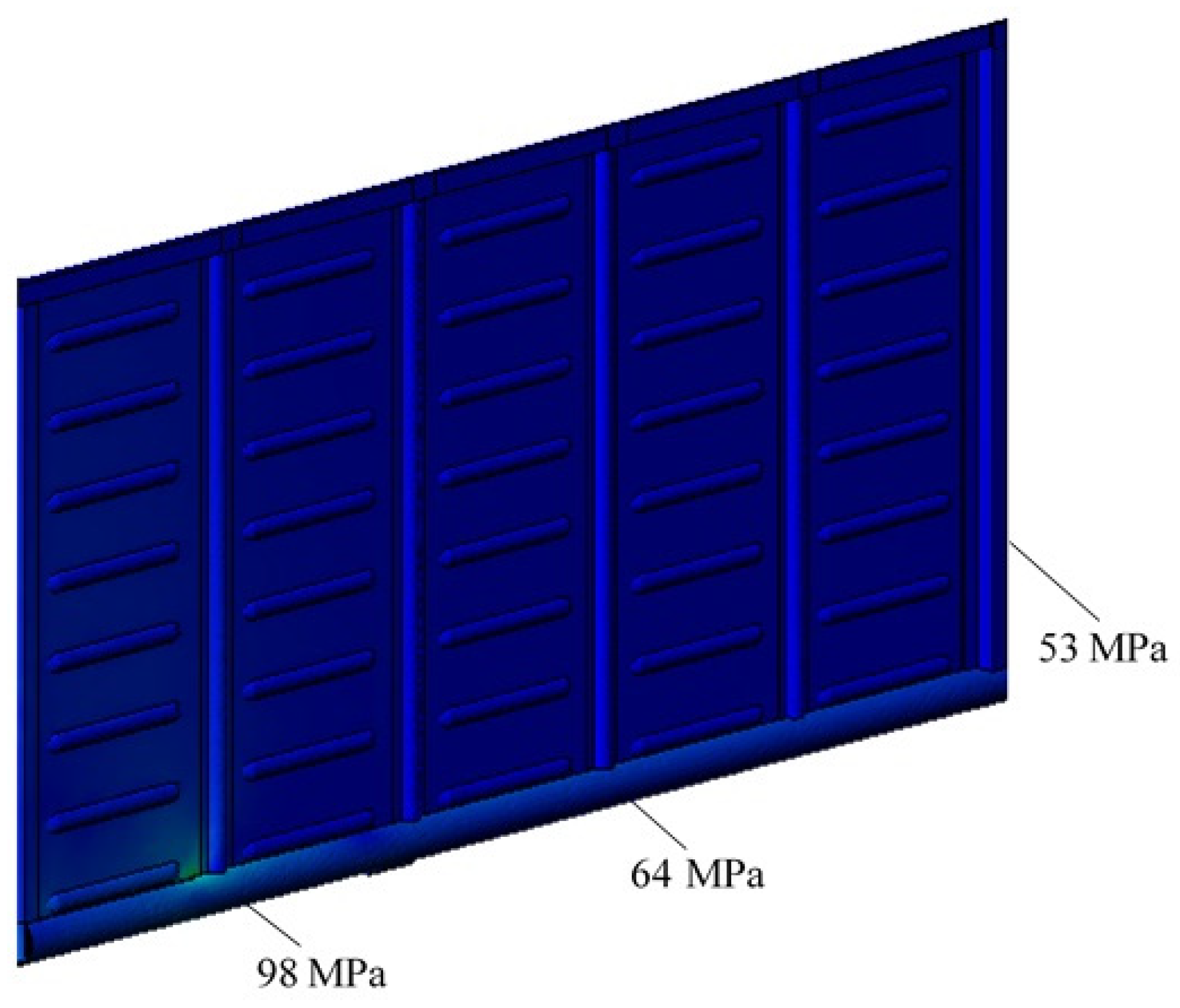
In the side wall of the section the maximum equivalent stress was 98 MPa and was concentrated in the zone of interaction of the bottom chord with the bolster post (
Figure 18).
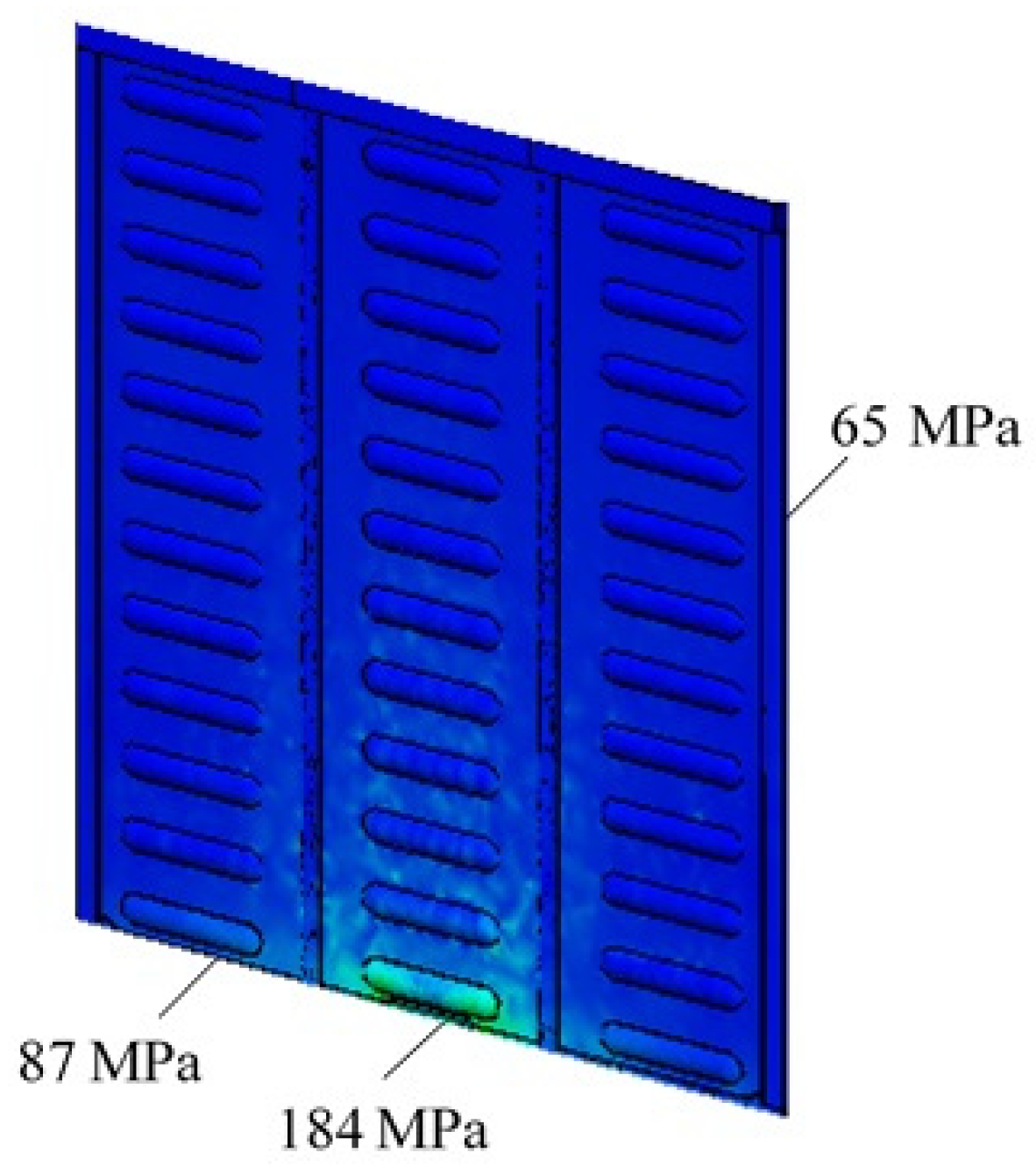
In the section end wall the maximum equivalent stress was concentrated in the bottom part and amounted to 184 MPa (
Figure 19). The stress decreased towards the top of the wall.
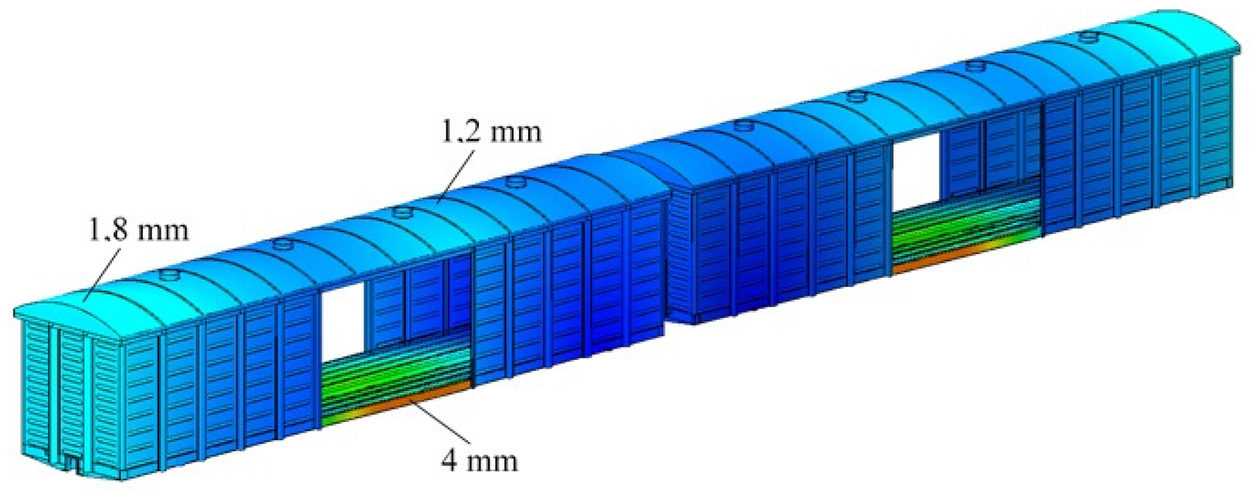
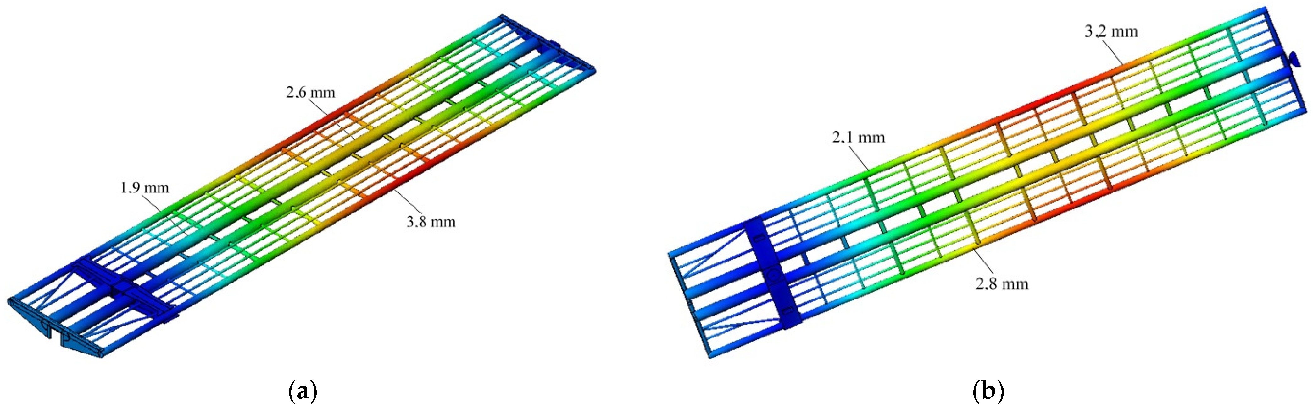
The maximum displacement was found for the main longitudinal beams of the sections and was about 4 mm (
Figure 20 and
Figure 21).
The maximum displacement was 2.6 mm in the middle parts of the sections’ center sills and 1.5 mm in the cantilever parts.
The distribution of maximum displacements along the length of the center sill of the first wagon section from the side of the longitudinal force action is shown in
Figure 22.
In the roof nodes the maximum displacement was 1.3 mm (
Figure 23).
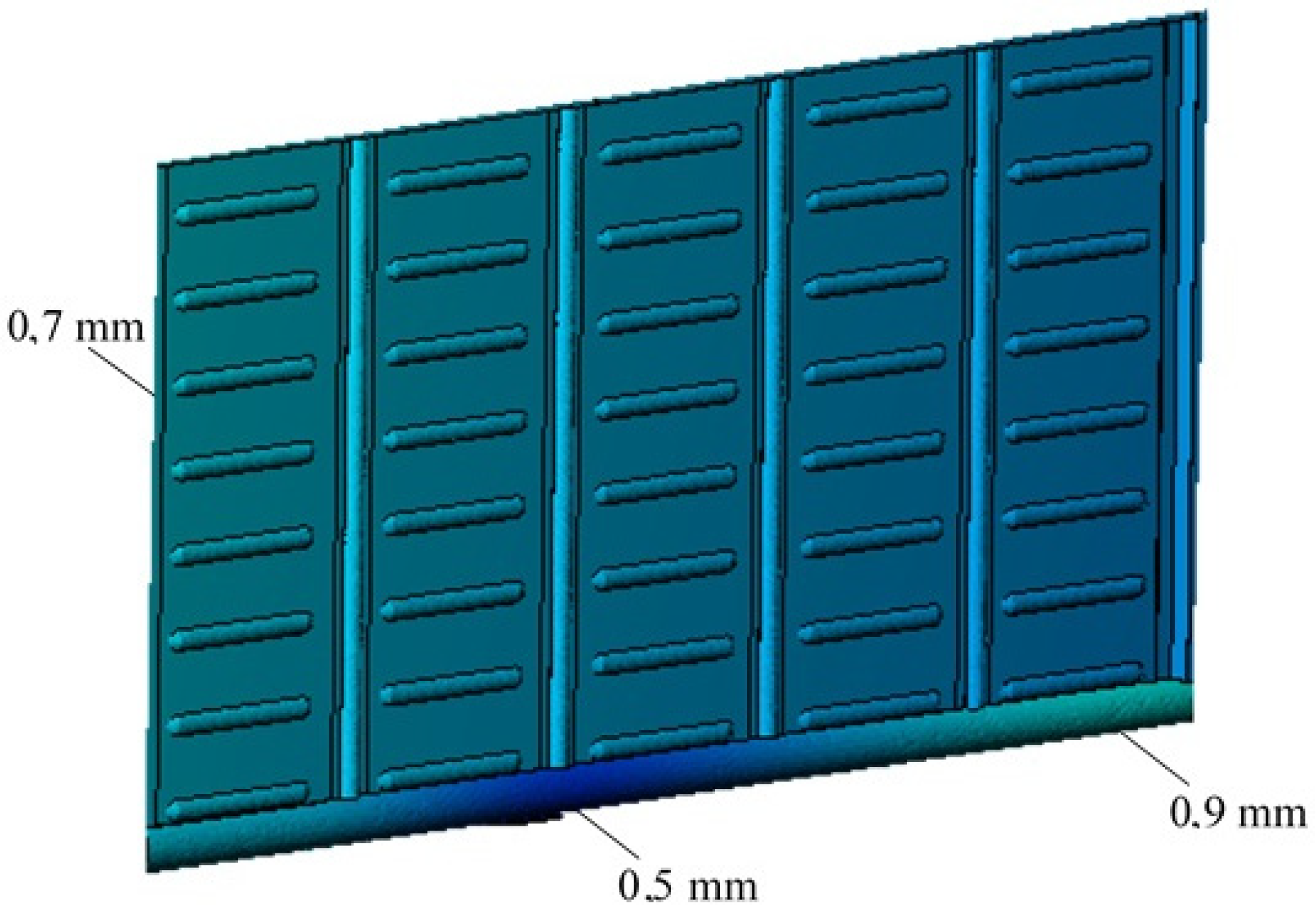
In the side wall the maximum displacement was 0.9 mm (
Figure 24). The displacement was 0.5 mm in the area of interaction between the bolster post and the main longitudinal beam of the section frame.
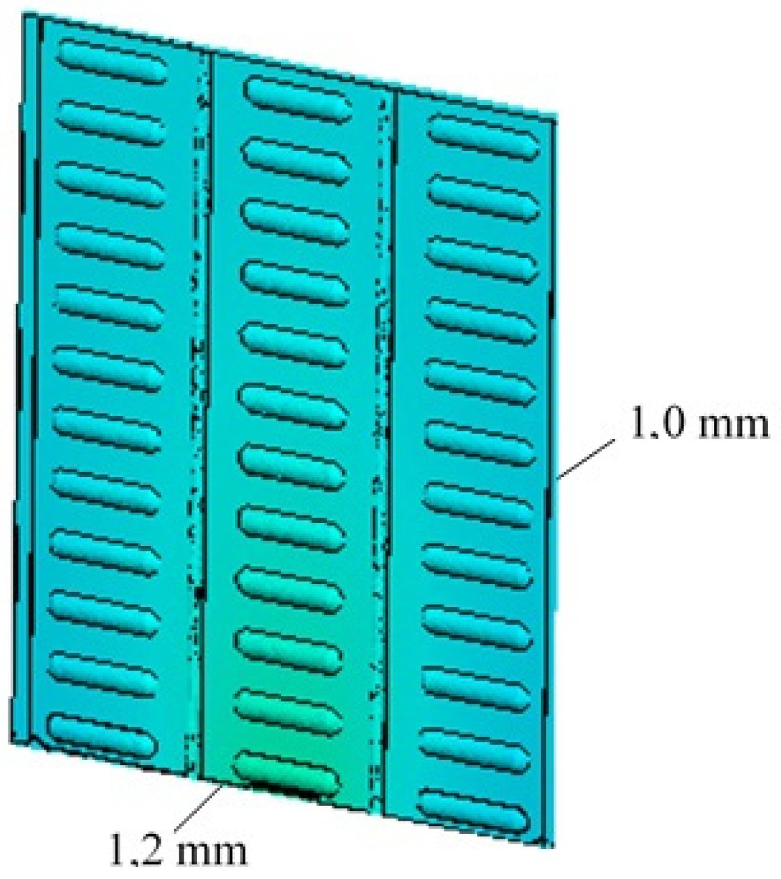
In the end wall the maximum displacement was 1.2 mm and the displacements were concentrated in the bottom part of the wall (
Figure 25).
Towards the top of the wall, the displacements were reduced to about 1 mm.
8. The Fatigue Strength Analysis of the Articulated Covered Wagon Body-Supporting Structure. Determination of the Design Life
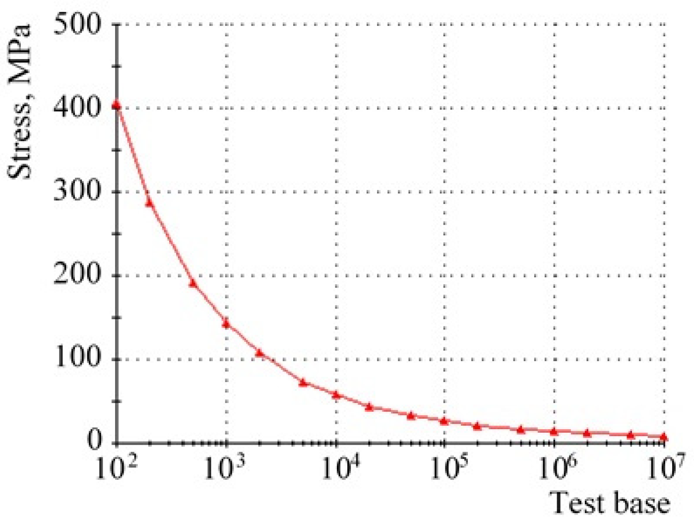
The fatigue curve of the covered wagon supporting structure material is shown in
Figure 26.
The calculations made it possible to conclude that the fatigue strength of the articulated covered wagon body-supporting structure could be determined from a given test base.
The technique described in [
30,
31] was used to determine the design life of the articulated covered wagon body-supporting structure. In this case, the design life of the wagon was determined by Equation (7):
where
is the average value of the endurance limit, MPa;
n is the permissible assurance factor;
m is a fatigue curve exponent;
N0 is a test base;
B is a coefficient that characterizes the time of continuous object operation expressed in seconds;
fe is an effective frequency of dynamic stresses, s
−1; and
σae is an amplitude of equivalent dynamic stresses.
The coefficient that characterized the time of continuous object operation was determined using Equation (8):
where
La is the average daily wagon mileage, km (≈250 km [
30]);
ϑa is the average wagon speed, m/s; and 0.34 is the empty run ratio.
The effective frequency of dynamic stresses was calculated with Equation (9):
where
fst is the static spring deflection, mm.
In the calculations, the following input parameters were used: the average value of the endurance limit was determined as 0.5·σE of a material (steels 09G2D and 09G2S) and amounted to 245 MPa; the test base was taken as 107 cycles (recommended test base for steel); continuous operation time at ϑa = 33.3 m/s was taken to be 6514.37 s; the effective frequency of dynamic stresses was determined by taking into account the parameters of the spring suspension of bogies 18–100 and amounted to 2.7 Hz; the allowable safety factor was taken to be equal to 2; the fatigue curve exponent for a welded construction was taken to be equal to 4; and the amplitude of equivalent stresses was determined on the basis of strength analysis and amounted to 51.6 MPa.
Based on the calculations, it was found that the wagon design life is at least 32 years.
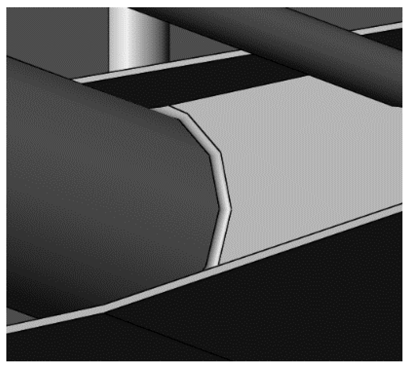
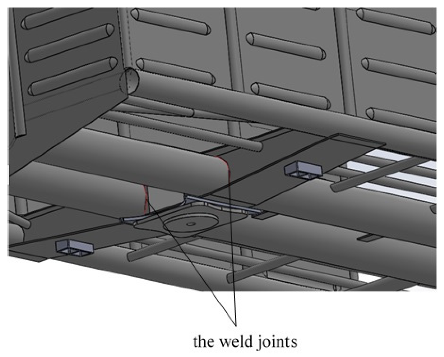
9. The Strength Analysis of the Weld Joint in the Interaction Area of the Center Sill and the Bolster Beam
The strength analysis of the articulated covered wagon body-supporting structure showed that one of the most loaded nodes was the interaction node of the center sill and the bolster beam. The joining of these structural elements with each other was carried out by welding (
Figure 27 and
Figure 28).
To ensure the strength of the articulated covered wagon body-supporting structure, a strength analysis of the weld joint in the interaction area of the center sill and the bolster beam was carried out.
This node underwent the following strains during operation: tension–compression, bending and torsion [
32,
33]. In light of this, we used the method for calculating welds presented in [
34,
35,
36]. Based on our practical experience of carrying out such calculations, the proposed method is simple and sufficiently reliable.
The stress from the longitudinal force action was determined by using Equation (10) [
34,
35,
36]:
where
F is a longitudinal force acting on the weld;
k is a weld leg; and
d is a pipe diameter.
The stress from the bending moment action was calculated with Equation (11):
where
M is the bending moment acting on the weld.
The stress from the torque strength action was calculated with Equation (12):
where
T is the torque strength acting on the weld.
The total stress was calculated with Equation (13):
Permissible stresses for the parent metal can be determined using Equation (14):
where
is the yield stress, MPa.
Then, at
σY = 345 MPa, we have
Taking into account the geometric parameters of the pipe section and the bolster beam web plate, τΣ = 192.78 MN was obtained, which was lower than the permissible value; that is, the strength condition of the weld fulfilled.
10. Discussion
To reduce the material consumption of the supporting structure of a covered wagon, it was proposed to construct it from round pipes. On the basis of the proposed structure, the supporting structure of an articulated covered wagon was created. The proposed technical solution made it possible to reduce the weight of the bearing structure of the covered wagon body in comparison to the prototype wagon by 4% (one pipe) and 4.84% (two pipes). In other words, this wagon design can reduce the cost of manufacturing in the conditions of car-building enterprises. In addition, the creation of articulated wagons makes it possible to reduce the cost of the trucks, since the use of three bogies can be considered for two sections.
The dynamic loading of the covered wagon bearing structure was determined by mathematical modeling. In this case, the presence of three degrees of freedom for each section was taken into account. In further research in this direction, we plan to analyses the dynamic loading of the wagon supporting structure in the vertical plane.
The results obtained by means of mathematical modeling were confirmed and verified by computer modeling. When carrying out the calculations, the rigid fastening of the supporting structure was assumed; that is, possible clearances between the nodes of interaction between the supporting structure and the bogies were not taken into account.
The main indicators of the strength of the proposed covered wagon bearing structure were determined. The strength of the bearing structure of the covered wagon was ensured. However, at this stage, the calculation was performed in quasi-statics.
The fatigue strength and design life of the covered wagon bearing structure were investigated. It was found that with a test base of 107, the fatigue strength of the supporting structure was ensured. The design service life of the covered wagon supporting structure was judged to be at least 32 years. We also determined the strength of the welded joints at the most loaded elements of the supporting structure.
The results of the analyses of the dynamic loading, strength, fatigue strength and design service life allow us to conclude that the use of circular pipes as elements of an articulated covered wagon supporting structure is expedient.
In further research in this direction, it is important to experimentally determine the dynamic loading and strength of the covered wagon bearing structure. This can be done through the method of similarity using an electric strain gauging. Also, the issues that arise in researching the running characteristics of articulated wagons made of round pipes generate interest.
The proposed research direction will be developed in a study of the expediency of using fillers for the round pipes from which the supporting structure is made. This will reduce the load on the wagon in operation, as well as improve the anti-corrosion properties.
The research carried out will contribute to improving the efficiency of railway transport operations.
11. Conclusions
Based on the calculations, we can make the following conclusions:
The design of an articulated covered wagon was created, the body-supporting elements of which were made of round pipes. The proposed solution made it possible to reduce the weight of the covered wagon body-supporting structure compared to the prototype wagon by 4% (one pipe) and 4.84% (two pipes). To increase the volume of cargo transportation, an articulated wagon was developed on the basis of the proposed covered wagon design. When using bogies 18–100, its gross weight should not exceed 1383.21 kN. Alternatively, it is possible to use bogies with increased axial load under such a wagon.
Mathematical simulation of the dynamic loading of the articulated covered wagon supporting structure was carried out. The calculation was carried out according to the Runge–Kutta method in MathCad software. The study results led to the conclusion that the acceleration acting on the first section of the supporting structure from the longitudinal force action side was 28.4 m/s², and the acceleration acting on the second section of the supporting structure was 27.9 m/s².
Computer simulation of the dynamic loading of the articulated covered wagon supporting structure was carried out. It was found that the maximum acceleration acting on the first section from the side of the longitudinal force action was about 32.4 m/s2, and the maximum acceleration acting on the second section was 31.7 m/s2. At the same time, the maximum acceleration was concentrated in the sections’ middle parts. Towards the sections’ console parts, the acceleration decreased and amounted to 23.4 m/s2 (first section) and 22.6 m/s2 (second section).
The validity of the developed models of the dynamic loading of the articulated covered wagon bearing structure was checked. The F-criterion was used for the calculations. It was determined that with an adequacy variance of Sa = 33.6 and repeatability variance of Sr = 25.8, the criterion design value did not exceed that from the table. Therefore, the adequacy hypothesis was not rejected.
A strength analysis of the articulated covered wagon supporting structure was carried out. The finite element method, implemented in CosmosWorks software, was used in the calculation. The maximum equivalent stress arose in the zone of interaction between the center sill and the bolster beam and was about 300 MPa; that is, it did not exceed the allowed values. The maximum displacement arose in the sections’ main longitudinal beams and was about 4 mm. It can be seen that the loads of the structure were distributed symmetrically with respect to the longitudinal structure.
The fatigue strength of the articulated covered wagon body-supporting structure was calculated. The fatigue curve was obtained by dividing each numerical stress value of the SN reference curve by the elasticity modulus of the ASME reference material and multiplying the obtained value by the elasticity modulus of the current material. It was established that, for a given test base (N = 107), the strength of the articulated covered wagon body-supporting structure was ensured. The design life of the articulated covered wagon was calculated. The calculation results showed that the wagon design life would be at least 32 years.
A strength analysis of the weld joint in the interaction area between the center sill and the bolster beam was carried out. Tension–compression, bending and torsion strains were taken into account. Taking into account the geometric parameters of the pipe section of the center sill and the bolster beam web plate, the total stress value τΣ = 192.78 MN was obtained, which was within the permissible limits.
It is important to say that the theoretical studies carried out made it possible to verify the expediency of using circular pipes as bearing structural elements, as well as to form an algorithm for the calculation of the supporting structure of an articulated covered wagon made of circular pipes under the most unfavorable loading mode in operation, which has not been previously covered in scientific publications.
The conducted studies will contribute to reducing the cost of manufacturing wagons at the design stage, as well as increasing the efficiency of railway transport operations.
12. Patents
Fomin, O.V.; Lovska A.O. Covered wagon: pat. 111572 Ukraine: IPC (2016.01) B61D 3/00 B61F 1/00 B61F 1/02 (2006.01) B61F 1/08 (2006.01) B61D 17/04 (2006.01) B61D 17/08 (2006.01) B61D 17/12 (2006.01); application 18 September 2015; publ. 10 May 2016. Bull. №9. (In Ukrainian)
Panchenko, S.V.; Fomin O.V.; Lovska A.O. Covered wagon of articulated type: pat. 145219 Ukraine: IPC (2020.01) B61D 3/00 B61D 17/00 B61F 1/00 B61F 1/02 (2006.01) B61F 1/08 (2006.01); application 07 July 2020; publ. 25 November 2020, Bull. №22. (In Ukrainian)


 ,
, 


