Abstract
The paper discusses a method for obtaining a matrix of individual and group composition of a hydrotreated heavy gasoline fraction in industrial conditions based on the fractional composition obtained by the distillation method according to the ASTM D86 (the Russian analogue of such a standard is GOST 2177). A method for bounds estimation of the retention index (RI) change is considered on the basis of the symmetry of the RI change range relative to its arithmetic mean. Implementation of this method is performed by simulation of individual composition of C6–C12 feedstock of the catalytic reforming unit in the software package. For this purpose, the boiling curve of individual composition of hydrocarbon mixture is converted into the corresponding curve of fractional composition. The presented technique of creating a virtual soft sensor makes it possible to establish a correct relationship between the fractional composition and the individual hydrocarbon composition obtained according to the IFP 9301 (GOST R 52714) (Russian GOST R 52714 and international IFP 9301 standards for the determination of individual and group composition of hydrocarbon mixtures by capillary gas chromatography). The virtual soft sensor is based on chemical and mathematical principles. The application of this technique on the data of a real oil refinery is shown. Obtaining accurate data by means of a virtual soft sensor on the individual composition of feedstock will make it possible to optimize the catalytic reforming process and thus indirectly improve its environmental friendliness and enrichment efficiency.
1. Introduction
Digitalization of the economy in general [1] and industry in particular [2] is a top national priority of the Russian Federation. Digitalization of technological processes in this case is associated with their advancement [3]. Currently, development of technological processes of oil refining is carried out with the help of improvement of technology [4,5] and control systems and control principles of these technological processes [6]. In this case, technological development means everything that is related to technology: advancement of apparatus design, replacement of equipment, reagents, etc. Improvement of control systems and principles means creation of new control algorithms and principally new by structure and functionality automated control systems. The development of primary oil refining processes is mainly due to the introduction of so-called advanced control systems (APC), which have already been proven to bring substantial profits to oil refineries [3].
However, secondary oil refining processes are directly related to improvements in technology [7,8]. For example, moving bed catalyst reactors are used instead of a fixed bed reactor or development of new types of catalysts that increase conversion and efficiency of processes in chemical reactors [5]. Meanwhile, improving the control systems and control principles of secondary oil refining processes is not considered a priority task. This is due to several reasons: (1) Significant profit from technological advances overshadows the profit from system advances. (2) New techniques do not allow the formation of significant experience in the automation of these processes, and therefore decisions concerning advancements of systems can be considered hasty and lacking adequate substantiation. (3) Low flexibility of the process, most parts of which can rather be perceived as a black box with no chance to change the contents. (This is due to the peculiarity of reactor processes. As a rule, the controls are made in such a way that those control actions that are applied to the reactor input give their result at the output of the apparatus. We can only change something with a loss of quality for a period of time. The change occurs intuitively, because there are no control actions while the substance is in the apparatus; however, there are many influencing factors: coke formation, reduction of the reactivity of the catalyst, etc. Therefore, from the point of view of control, the apparatus is a black box, since it is impossible to monitor the state of the substances inside the unit.) (4) The complexity of chemical processes that are difficult to determine. (5) High cost of equipment for the study of these processes, etc. However, taking into account these issues, the use of APC algorithms along with technological developments will certainly increase the efficiency of secondary oil refining processes, as well as bring additional profit to oil refineries [9,10]. Although advanced control systems are based upon mathematical models, it is difficult to obtain accurate mathematical models describing a process in petroleum or a related field [11]. This applies to both mathematical kinetic and empirical models. For kinetic models, it is difficult to obtain a complete list of reactions of the process. For empirical models, it is insufficient information about the process, which makes it complicated to accumulate data to build empirical models. In this regard, the work aimed at improving the information component of the system is relevant.
Data about the hydrocarbon components contained in naphtha is used to monitor the catalytic reforming process, assess product quality, and control composition. Extended hydrocarbon composition can be obtained by chromatography. If chromatography is used to identify compounds, the retention time should be independent of the amount of sample and the chromatographic peaks should be symmetrical to ensure correct identification of the compounds. The extended hydrocarbon composition is also used as input for mathematical modeling of the process. It should be kept in mind that data obtained by chromatography cannot be extracted in real time. Usually, they are received in the laboratory over a period of at least two hours with human participation. Soft-sensing technology is used in various industries and technological facilities. The application, algorithmic and mathematical bases for these sensors are very diverse and are mainly based on neural networks, regression methods, and composition prediction. The paper by Tian et al. (2021) [12] presents soft sensor applied in the monitoring system of a typical 330 MW CHP plant. This approach uses the turbine’s Flugel formula as a static model, the turbine’s heat balance characteristic to correct the coefficient in the model and the butterfly valve characteristic to realize dynamic compensation to realize the soft sensor. The work Niño-Adan and colleagues (2021) [13] discusses soft-sensor for class prediction of the percentage of pentanes in butane at a debutanizer column. It includes the autoML approach that selects among different normalization and feature weighting preprocessing techniques and various well-known machine learning (ML) algorithms. The article by Winkler et al. (2021) [14] presents soft sensor for real-time process monitoring of multidimensional fractionation in tubular centrifuges. Reference [15] describes Soft sensor for industrial distillation column. The authors Hsiao et al. (2021) propose soft sensor development methodology combining first-principle simulations, and transfer learning was used to address these problems.
One of the elements of advanced control systems is the virtual sensor [16]. Virtual sensors calculate parameter values using statistical dependencies (a polynomial), a neural network, or other mathematical tools to determine correlation between variables [17,18]. This method involves the accumulation of a large volume of data and its further processing using various approaches [19] including those mentioned earlier. For a catalytic reformer, various variables can act as deterministic parameters for the virtual sensor. However, in some cases, the creation and implementation of virtual sensors for some variable process is highly difficult and even impossible. This is due to the fact that the large sample of data history for this segment does not exist, or their synchronization is troublesome. In particular, to be more specific, the process of creating a virtual soft sensor of the feedstock composition is a challenging task. The reason for this is the mismatch between the company’s capabilities to measure individual hydrocarbon composition in a number of industrial processes and the data requirements of the virtual sensor. In this case, data obtained on the individual hydrocarbon composition of the feedstock in real time is an effective tool for optimizing technological processes that take place in a catalytic reforming unit. The need to optimize technological processes in this matter is caused by tough requirements for environment protection [20] and the influence of the modern trends in the development of the global energy sector [21,22].
It is important to reduce the uncertainty arising from infrequent composition control in processes such as catalytic reforming where the individual and group composition of the feedstock determines the target performance of the unit and the catalyst lifespan. Such uncertainty in the feedstock composition can complicate the application of mathematical models in the loop of an advanced control system or as an advisor to the operator [23], which can result to fluctuations in product target performance over the specification limits in the absence of the advanced control system. Studies of naphtha catalytic reforming process have been carried out for a long period of time [24]. During this period, a large number of [25] complex, highly precise, and detailed mathematical models of the catalytic reforming process, simulating different naphthas with various amount of detail, have been developed. The following steps were highlighted in the study of research and work: the effect of changes in feedstock composition at the naphtha catalytic reforming unit is considered [26]; consider the parameters of the working process of coke combustion, comparing the results with industrial data [27]; conduct a comprehensive sensitivity analysis of the quality and quantity of the product [28] without taking into account the impact of changes in the composition of raw materials of the process; the influence of the design parameters of a catalytic reforming reactor, the molar flow rate on the hydrodealkylation side, the molar ratio of hydrogen to hydrocarbons, the impact of catalyst deactivation on the system performance are subjected to the research [29]; the modes of incoming and outgoing flows in reactors with thermal coupling are analyzed [30].
A certain technological level of the unit that meets the requirement of the mathematical model for the size of the input matrix is needed to introduce the developed mathematical models in the existing production facilities. The model input matrix can be obtained from the results of analytical control of the individual hydrocarbon composition of raw materials, but inline control is not applied at all refineries. This raises the question of how to provide the mathematical model with up-to-date input information about changes in the composition of the workflow under operating production conditions, and whether this control of the feedstock composition of a catalytic reforming unit can be performed more frequently at an operating production facility.
A review Ren and colleagues (2019) [31] of methods for converting individual composition into fractional composition and vice versa showed several approaches. Most of the approaches are formed on a multidimensional base for controlling several parameters besides composition, which implies a preparatory stage of model development. Incomplete data and checking their correctness results in the use of data processing and recovery methods. The researchers consider the dependences of the mixture properties on the compound identification parameters [32,33,34], individual constants, and characteristics of the compound [35], which is an important and necessary basis for this study.
The paper discusses a method for obtaining a matrix of the carbon number and group composition of the feedstock of a catalytic reforming unit in industrial conditions. A group composition of petroleum fractions during an oil refining processes is the most important factor influencing in the yield and composition of products, as well as an efficiency of the catalysts. The fuels ASTM D86 distillation temperature distribution is divided into equal-volume pseudo-component cuts, each of which is assigned a property volume blending index the aggregation of which provides an accurate estimation of the global property of the whole petroleum fuel, or portions thereof. The list of these pseudo-components is the group composition of petroleum fractions [36]. It is envisaged that it is possible to find a matrix of carbon number and group composition of hydrotreated catalytic reforming naphtha close to the experimental one by expressing [37] the desired composition through close fractions of known individual hydrocarbon compositions. The evaluation of the fraction proximity is determined by the associated boiling points. This is known due to the fact that the heavier in molecular weight individual components that make up the fractions have higher boiling points than the lighter ones.
The retention index is a common type of data used to identify chemical compounds by gas chromatography. The retention index system is a widely used and recognized system in gas chromatography for the identification of compounds. The paper by Yan et al. (2015) [38] describes that the database retention indices of over 300 aroma compounds that were determined on three capillary columns of different polarity can be used for qualitative identification. The work [39] shows that retention indices of 28 polychlorinated biphenyls in capillary gas chromatography referred to 2,4,6-trichlorophenyl alkyl ethers as RI-standards. The paper by Morosini and Ballschmiter (1994) [39] presents that on the basis of the TCPE, the retention indices of 28 polychlorinated biphenyls were determined using the ECD, a 95% dimethyl 5% phenyl polysiloxane phase and six different temperature programs. In addition, there are a number of studies in practice that have generated a system of retention indices in different ways [40,41,42].
2. Materials and Methods
The development of a model for a virtual soft sensor of the feedstock composition can be divided into two stages: preparatory and computational. The preparatory stage includes the analysis and processing of the obtained data, determination of the method of obtaining fractions from the individual composition, and the formation of a database of individual components and associated boiling points of fractions. The description of the preparatory stage is formed on the lack of information on the chromatographic system and the fractional composition control system based only on the available measurement data. A chromatographic system is defined as a set of hardware and methods that allow chromatography to be performed. The need of these operations at each stage will be discussed further.
According to the technological regulations of the enterprise, the individual and group composition is controlled according to the IFP 9301 standard, which recommends the use of gas chromatography with a 100 m long fused-silica capillary column with an inner diameter of 0.25 mm. According to the standard, the capillary column is coated with methylsilicone elastomer or dimethylsiloxane, 0.5 μm thick, and has to be equivalent to at least 6000 theoretical plates/m; a linear retention index (n-alkane) is used to identify the components. The fractional composition is controlled according to the ASTM D86 method.
2.1. Preparatory Stage
Check the presence and repeatability of the distribution law in the IFPi homologous series. If the data obey the distribution law, then composition models based on these laws can be used. Determine the retention time of non-absorbent substance and possible parameters of the chromatographic system for the identification of compounds [37]. However, reference sources on retention indices provide single values for individual substances and there are no confidence interval limits of their measurement, which leads to uncertainty in identification [43]. If the report on the control of individual and group composition of raw materials records the given time, then calculate the matrix of minimum ΔRI from all reports for each homologous group by carbon number by Equation (1):
where ΔRI is the difference in the retention indices of adjacent compounds in the report, RIi is the retention index of the i-th compound, and RIi-1 is the retention index of the previous compound to the i-th. The chromatographic system identifies a component by its retention index, and therefore it is important that the maximum deviation from the mean in the retention index of each compound in different reports does not exceed the ΔRI value for the corresponding homologous group of a matrix of minimum ΔRI. If the value of deviation of the retention index exceeds the corresponding ΔRI, then this indicates that the data are incorrect, and that compound cannot be correctly identified. Moreover, the matrix of minimum ΔRI and average values of the retention indices can be used as an indicator of the chromatographic system performance, automatically checking the deviations of the new composition measurement, since visual assessment of the chromatogram allows for human error.
ΔRI = RIi − RIi-1,
For identified compounds with unknown boiling point the experimental values of the parameter are taken from the reference sources [35]. Construct the function between the normal boiling point of a compound and its retention index within one homologous series [33,44]. For unidentified compounds, determine its boiling point according to the constructed mathematical relation.
Determine actual ASTM boiling point intervals (min and max) for a given period of unit operation. In this case, the period of operation of the unit should be representative (historical data should cover the entire range of variation in the feedstock composition). This will allow for assessment of the range of change in the fractional feedstock composition.
Construct theoretical curves [45] corresponding to the mixture distillation simulated curves. The obtained simulated distillation curves are set in the Hysys/Pro II simulation program, specifying the composition of the mixture, which is the beginning of its boiling. Calculate the D86 boiling curve and enter the obtained values into the database as an associated fractional composition with an individual and group composition.
Theoretical curves are derived from the characteristic boiling points of the mixture from the individual hydrocarbon composition of the feedstock. The characteristic boiling points of a mixture are close values to the boiling points of the mixture at the corresponding cumulative fractions of the mixture. They uniquely characterize the entire mixture fraction taken in the interval of the corresponding cumulative fractions of the mixture by considering the boiling point of each compound of the fraction in accordance with the fraction occupied by this component in the given fraction of the given hydrocarbon com-position. Cumulative fractions are calculated in accordance with the principle of additivity of fractions of mixture components. The fraction taken from the individual hydrocarbon composition is considered separated from the rest of the mixture, and equated to 100%, the fractions of individual components in it are recalculated and used as weight coefficients when adding temperatures of each compound in the taken fraction. Thus, we obtain a unique temperature characterizing the fraction through the temperatures of the compounds of its constituents and close to the experimental boiling point of the mixture at the corresponding cumulative fraction of the mixture. The beginning of boiling of the mixture is determined on the basis of the algorithm of finding the experimental boiling points of the mixture. The obtained characteristic boiling points of a mixture of individual hydrocarbon composition are taken as a simulated distillation curve (SD) and, using the procedure 3A.3.2 API-TDB 1997 [46], convert them to an ASTM fractional boiling curve. We estimate the belonging of the obtained ASTM boiling curve according to the available actual boiling point ranges according to ASTM.
The prepared IFPi and their corresponding boiling points of the fractional composition are recorded in the non-relational database as the key value. The key in this case is the date of chromatography, associating the data of the two compositions, and the values are the report of the individual hydrocarbon composition and the corresponding boiling curve.
2.2. Computational Stage
Compare each point of the measured D86 boiling curve with the corresponding point by volume fraction point of the boiling curve from the prepared database. For comparison, we use the module of the difference between the measured and associated boiling point from the prepared database. A reference book with the keys of delta temperatures and values of chromatography dates with a length equal to the number of keys in the prepared database is created in the operating memory of the computer.
In the temperature delta reference book, search for the minimum temperature delta for each boiling point of the hydrocarbon mixture. As a result, one obtains a list consisting of an ordered sequence of dates and the corresponding boundary cumulative fraction of the hydrocarbon mixture.
The IFPi fractions sequence is determined from the list of dates. To obtain a sequence of fractions, we use the algorithm for obtaining a fraction from IFPi by cumulative fractions of the mixture by referring by date to the IFPi in the prepared IFPi database and the boundary cumulative fraction of the hydrocarbon mixture. We obtain a list of sequences of individual mixture components expressed from the nearest IFPi fractions. The resulting sequence is recorded in the database of estimated compositions for the possibility of performing analysis and statistical assessment of changes in the composition over time.
Obtaining the MTHS matrix (MTHS—molecular type and homologous series). We find the scoring matrix of the carbon number and group composition of the mixture. The method used to assess the proximity of the sought individual composition and the experimentally obtained composition requires reducing the IFPi to a matrix form. This covers the cases of repeating the dates at step 2 and possible duplicates of the names of the boundary components of the IFPi fractions. In this case, the values of the fractions of the components, for which the individual composition was incremented, are not repeated for the duplicate names, and do not violate the additivity principle of the mixture.
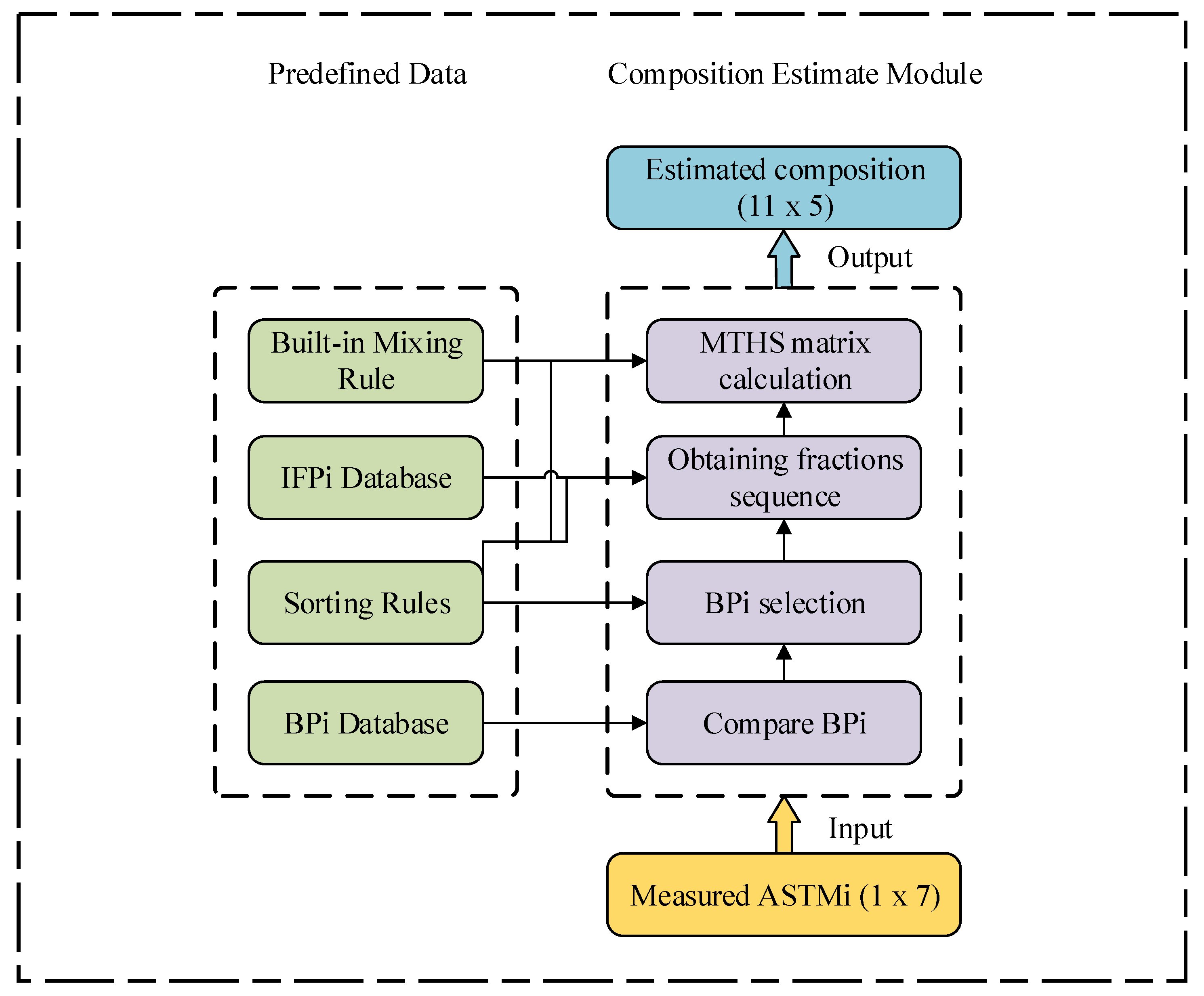
The Figure 1 shows the block diagram of the model for assessing MTHS composition by the ASTMi boiling.
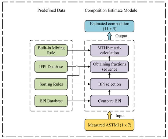
Figure 1.
Block diagram of the model for assessing MTHS composition by the ASTMi boiling curve. BPi Database is a list of associated boiling curves; sorting rules—sorting rules used to obtain the desired elements; IFPi Database—list of associated reports on the individual hydrocarbon composition of the mixture; built-in-mixing rule—incrementing the fractions of individual components is performed only with the corresponding fractions according to the principle of additivity of the mixture fractions; measured ASTMi (1 × 7)—boiling points (minimum 7 boiling points of a mixture), obtained during the in-process control of the fractional composition of the hydrocarbon mixture; compare BPi—calculation of deltas of measured and prepared boiling points of the hydrocarbon mixture; BPi selection—determination of the minimum deltas for each boundary value of the cumulative fraction of the mixture; obtaining fractions sequence—generation of a sequence of fractions of individual components; MTHS matrix calculation—calculation of the estimated MTHS matrix; estimated composition (11 × 5)—the resulting estimated MTHS matrix.
The measured ASTMi boiling curve of size 1 × 7 is fed to the input to the model. On the basis of the minimum temperature difference, the model determines the closest associated boiling point for each ASTMi boiling point fed to the input. According to the mixing rule, the MTHS matrix of the hydrocarbon mixture composition is calculated on the basis of the nearest boiling points of fractions found in the BPi virtual soft sensor database.
The presented virtual model of the soft sensor can be verified using four available reports of individual and group composition of the hydrocarbon mixture. These reports were created by monitoring the composition of the hydrotreated heavy gasoline fraction of a catalytic reforming unit (CCR) in different months of different years according to IFP 9301.
Let us conduct an experiment with the model, taking one of the four IFPi as unknown, and feeding the associated ASTMi boiling curve, taken as unknown associated IFPi, to the input to the model. As a result of the experiment with the model, we obtain the estimated MTHS matrix of the unit feedstock composition, taken as unknown. The estimated matrix is compared with the experimental matrix via reducing to the PIONA (paraffins, iso-paraffins, olefins, naphthenes, aromatics) vector, obtained by adding the respective fractions of compounds belonging to one of the five types of compound groups.
IFPi are represented by adsorption sequences of various lengths without repeating names, consisting of a list of individual components with diverse fractions of compounds in the mixture, with different boiling points. The various lengths of the reports and the difference in the positions of the same compound complicate assessing the proximity of the compositions in this form. However, the report on the considered raw materials can be reduced to an 11 × 5 matrix. The columns are the homological series, while the rows are the carbon numbers of the compound or several compounds of the same group. This approach will allow us to quantitatively assess the proximity of compositions by the components of the vector PIONA.
The accuracy of the data taken is determined by the accuracy of the DCS (distributed control system) and LIMS (laboratory information management system) systems operating on the unit, as well as by the accuracy of the sensor equipment used.
In addition, when describing the experiment, it is worth noting that the enterprise has internal standards that describe the required accuracy of the system operation and the laboratory tests carried out, which indirectly indicates the sufficient reliability of the data obtained in this manner.
3. Results
3.1. Statistical Descriptive Analysis of the Samples
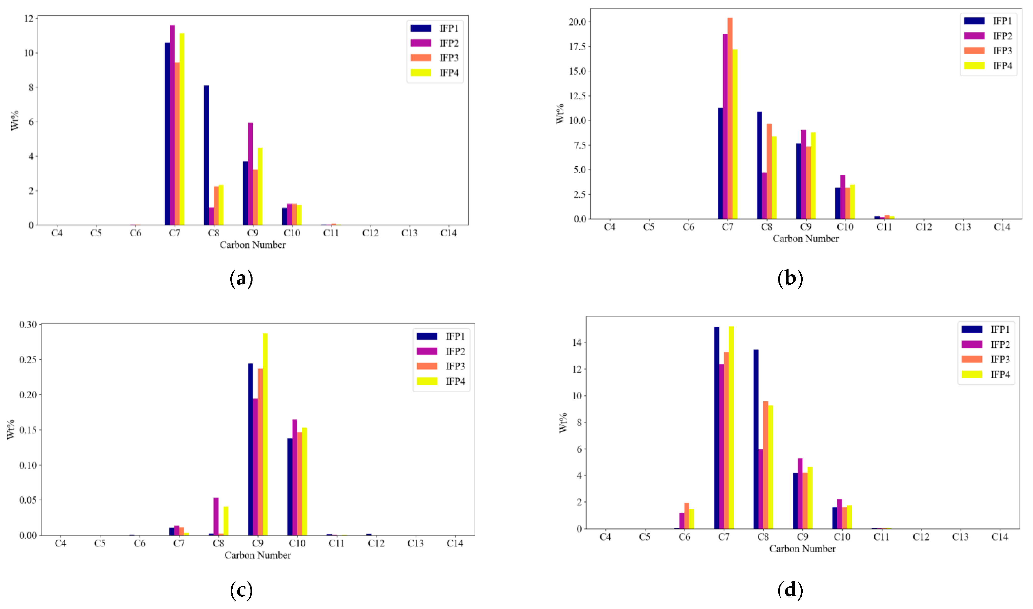
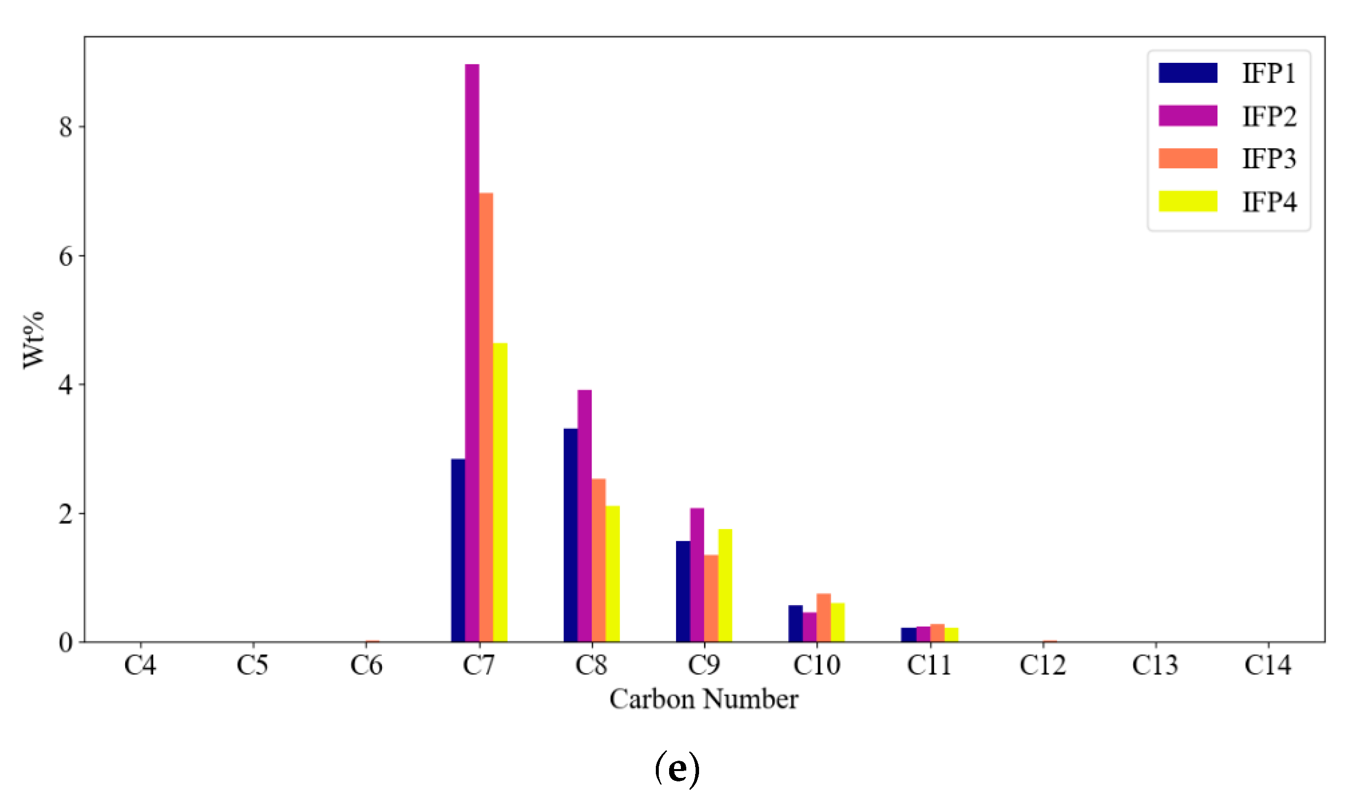
Before developing the model, we subjected the IFPi data obtained at the enterprise to statistical analysis. In particular, for each homologous series, a distribution histogram was constructed for four samples of the same catalytic reforming feedstock process stream, tested by the IFP 9301 method at different times (Figure 2a–e).
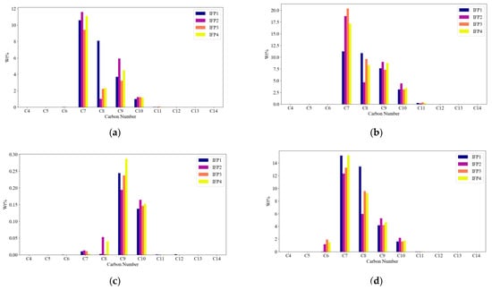
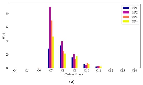
Figure 2.
Distribution histograms: (a) paraffins; (b) iso-paraffins; (c) olefins; (d) naphthenes; (e) aromatics.
As can be seen from the graphs, the distribution within each homologous group (paraffins, iso-paraffins, olefins, naphthenes, and aromatics) did not statistically obey any distribution function. This made it impossible to apply known models [9,47,48,49,50] based on the assumption of a change in composition in accordance with the known statistical distribution within the homologous group. The unevenness in the composition of raw materials and distribution by homologous groups can also be seen. At the same time, the low frequency of analysis of raw materials was associated with a stable composition; however, Figure 2 shows a contradiction. This fact additionally indicates the relevance of this work.
3.2. Retention Indices as a Marker for Component Identification in Homologous Groups
It was not possible to set the time for non-adsorbent compound, because the report recorded the adjusted retention time. When determining the matrix of minimum ΔRI, the values given in Table 1 were obtained.

Table 1.
Matrix ΔRImin for homologous groups of IFP1–IFP4.
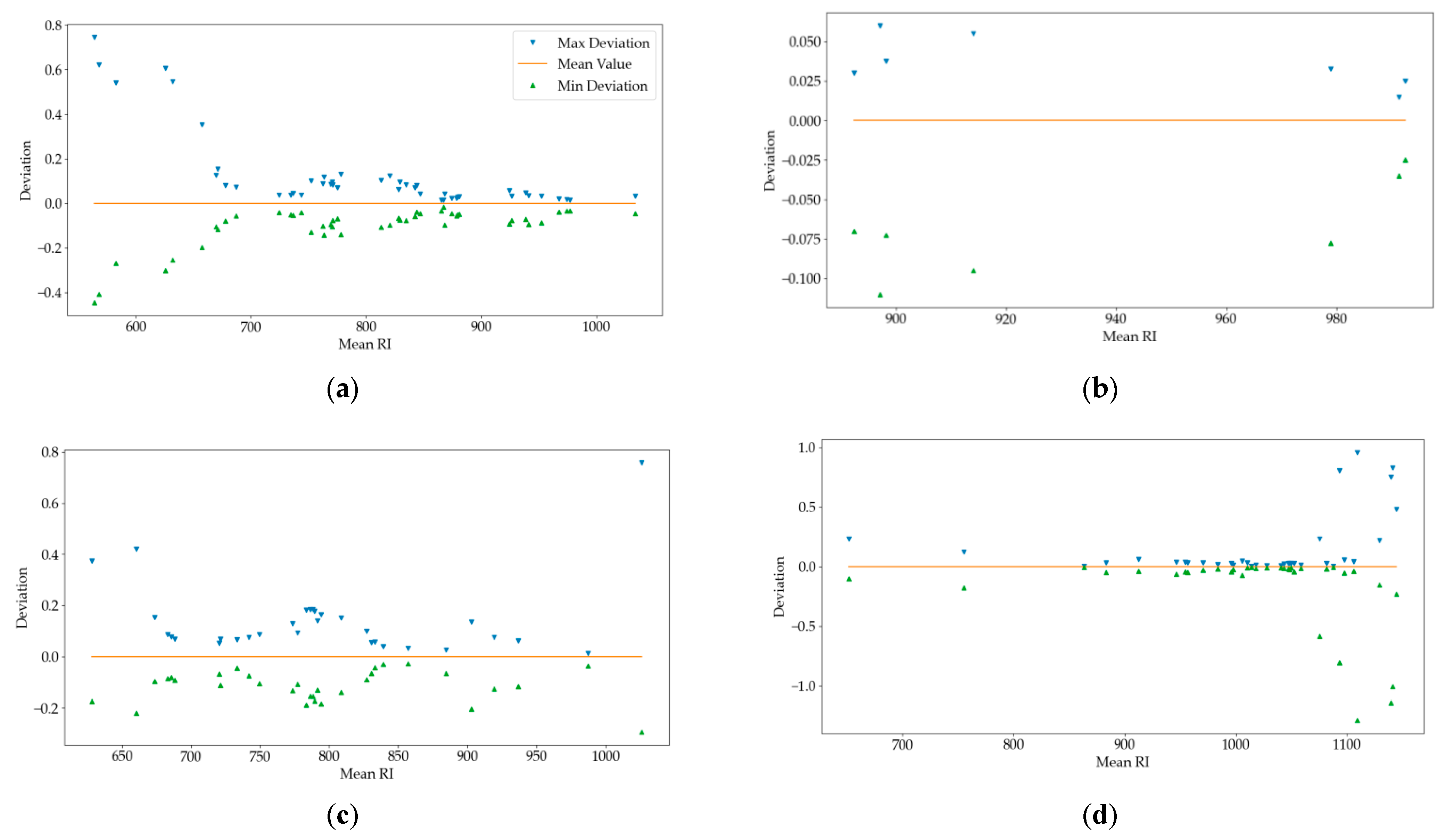
The first column of the table contains the numbers of carbon atoms; the title of the table contains the name of the homologous group. The least values of ΔRI from Table 1 are contained in I8 and N9. These and other cases are shown in Figure 3.
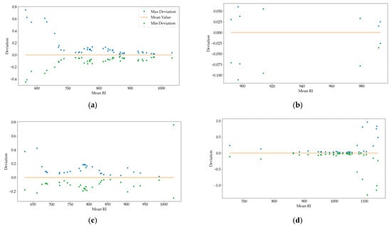
Figure 3.
Maximum deviation from the RI mean value for the identified components: (a) iso-paraffins; (b) olefins; (c) naphthenes; (d) aromatics.
Figure 3 shows the RI range from its arithmetic mean for each identified compound present in each IFPi. The RI ranges of the retention indices of the different compounds in the various homologous groups show the differentiation in the ranges of the RI retention indices of each compound and the inferred RI limits for the compounds. A symmetry with respect to the arithmetic mean RI can be observed. The deviation values show a tendency towards an increase in the spread of RI for light and heavy compound. The reason for this may be the methods and algorithms used to calculate the RI, as well as methods and instructions for performing the composition control procedure in production.
Let us consider the case of I8 with RI in the range of mean values from 724.503 to 777.97, where the maximum upper and lower boundaries for this group were reached at point 777.97 and its value was 0.27, which was less than 0.48 from Table 1. In the case of N9 with RI in the range of mean values from 830.515 to 936.827, the maximum upper and lower boundaries for this group were reached at point 902.905, with the value of maximum deviations of 0.34, which was less than 0.47 from Table 1. The inequality was valid for all PIONA corresponding pairs of RI values of all homologous series with the exception of a few aromatics and one olefin. Thus, the retention index is considered a reliable parameter for model development, therefore the reported data are valid. The retention index of the identified components were close and coincided with the retention index obtained in [51,52,53].
3.3. Identifying Components with “Drifting” RIs
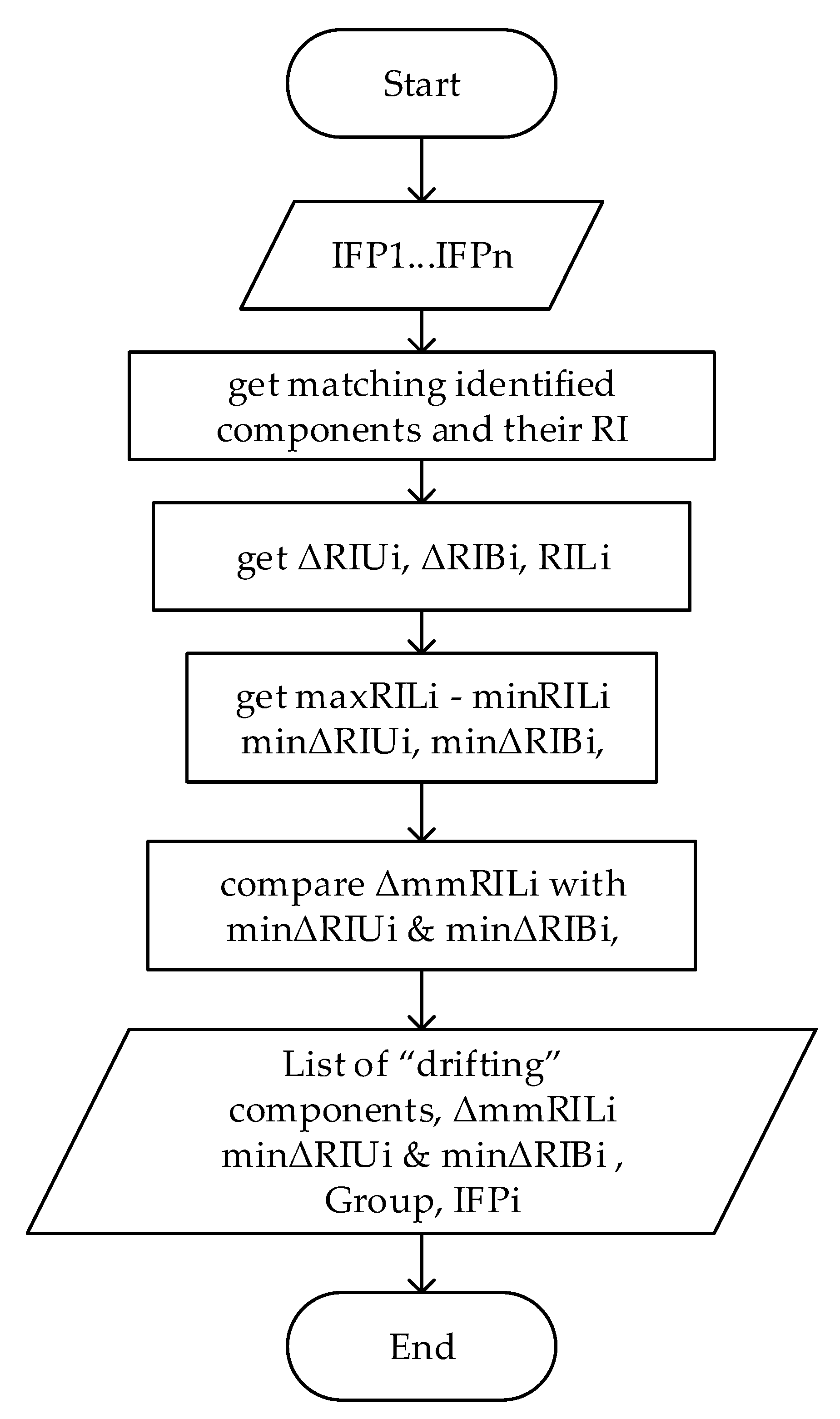
The Figure 4 shows the search algorithm for component with “drifting” RI.
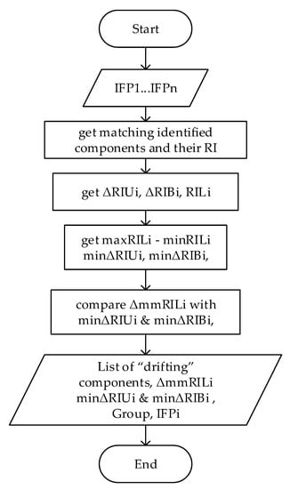
Figure 4.
Search algorithm for component with “drifting” RI. ΔRIUi—difference between the retention index of the current component and the retention index of the next component, ΔRIBi—difference between the retention index of the current component and the retention index of the previous component, RILi—list of retention indices of the current component, maxRILi—the maximum value of the retention index of the current component, minΔRILi—the minimum value of the retention index of the current component, ΔmmRILi—delta between the maximum and minimum value of the retention index of the current component (ΔmmRILi = maxΔRILi-minΔRILi), minΔRIBi—the minimum difference between the retention indices of the current compound name and the previous value in all reports, minΔRIui—the minimum difference between the retention indices of the current compound name and the next value in all reports.
Table 2 shows the result of the algorithm for finding drifting retention indices on experimental data. Components with drifting retention indices were identified. They all belonged to groups A10, A11, A12, and O11.

Table 2.
Search result for components with “drifting” RI.
3.4. Evaluation of a Chromatographic System
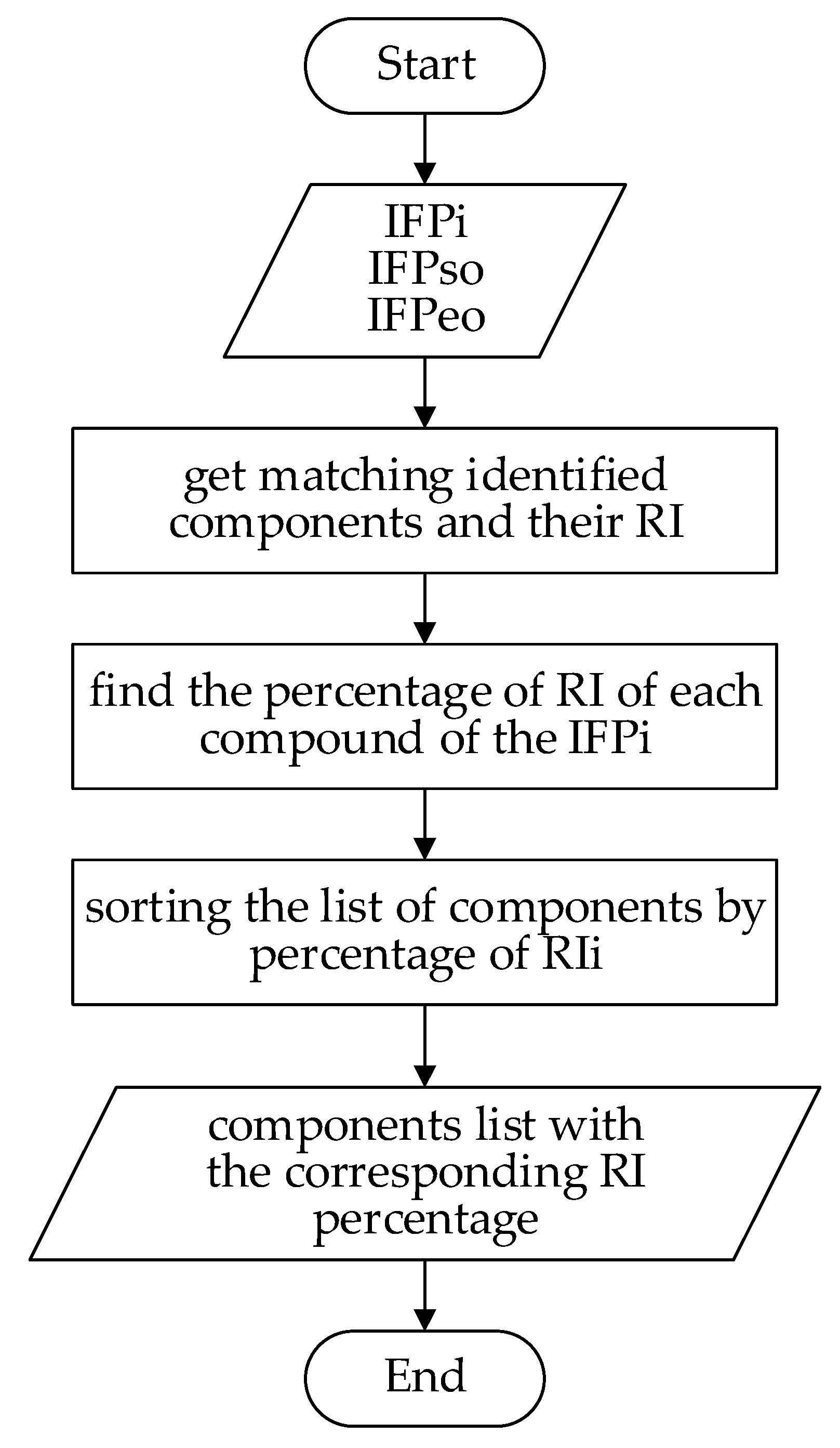
The change in the properties of the column during aging was assessed by the change in the retention index and the capacity factor k of benzene. Experimental methods were also used with a previously known composition of the mixture. Since the retention index is a reproducible parameter within a single chromatographic system, it can be used to evaluate a chromatographic system and change its properties over time. The Figure 5 shows the algorithm for evaluating the chromatographic system.
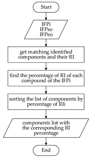
Figure 5.
Algorithm for evaluating the chromatographic system. IFPso—start of operation of the chromatographic column, IFPeo—the last measurement before replacing the chromatographic column (end of operation). Input reports should be on the same process stream. Only the corresponding reports on the control of the composition were submitted to the entrance.
3.5. Predicting Normal Boiling Points from RIs
In order to use the retention index as a parameter for assessing the normal boiling points of compounds, we carried out an analysis of the reports. The IFPi analysis identified three categories of data: unidentified compounds with unknown boiling points, unidentified compounds with known boiling points, and identified compounds with unknown boiling points. The component contribution to the mixture by category is shown in Table 3, Table 4 and Table 5.

Table 3.
Unidentified C7-C13 compounds with unknown boiling point.

Table 4.
Unidentified C9-C13 compounds with known boiling point.

Table 5.
Identified C9-C12 compounds with unknown boiling point.
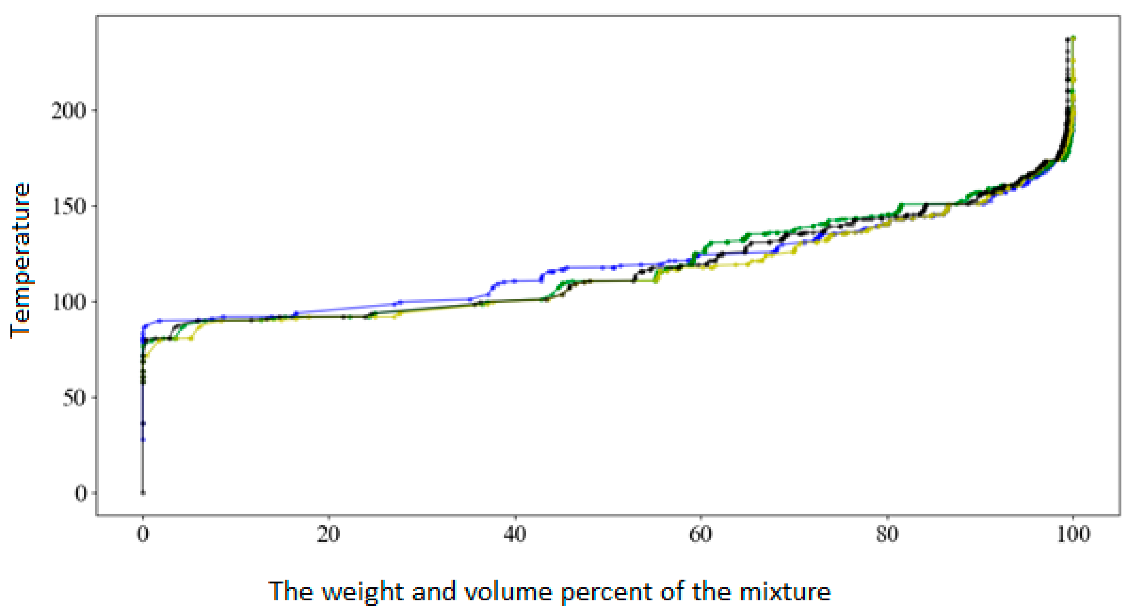
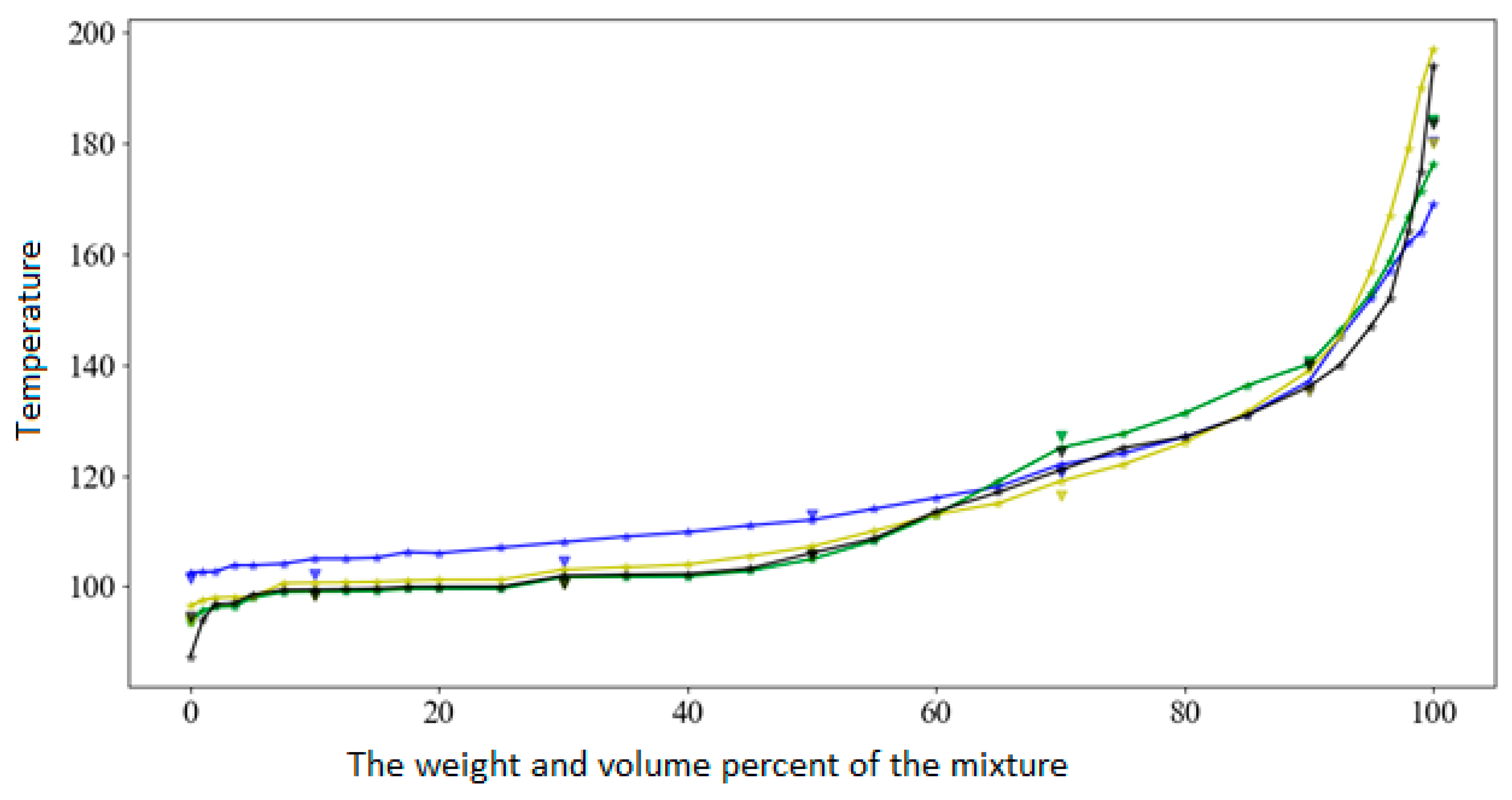
These tables show the estimated normal boiling points contribution to the theoretical curves shown in Figure 6 and Figure 7.
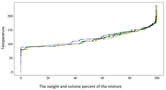
Figure 6.
The restored theoretical curves. Blue color—IFP1, green—IFP2, yellow—IFP3, and black—IFP4.
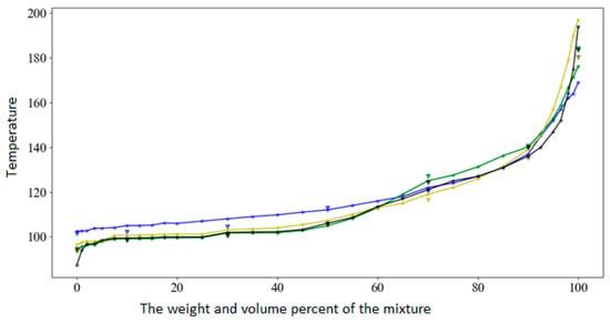
Figure 7.
The D86 boiling curves obtained from the theoretical curves by the pseudo-component method. Blue color—IFP1, green—IFP2, yellow—IFP3, and black—IFP4.
The restored theoretical curves are shown in the Figure 6. In the Figure 7, the D86 boiling curves obtained from the theoretical curves by the pseudo-component method are shown as solid lines. The triangular marker indicates the points of the D86 boiling curves obtained by the procedure 3A.3.2 from API–TDB 1997 on the basis of a sample of experimental data. The weight and volume percent of the mixture are located along the ordinate axis, and the temperature is located along the abscissa axis. Blue color was chosen for IFP1, green for IFP2, yellow for IFP3, and black for IFP4. The resulting D86 boiling curves corresponded to the D86 boiling curves obtained by the method of converting simulated distillation according to the ASTM D86. The difference in boiling points D86 from 10% to 90% inclusively did not exceed 1 °C. Differences more than 1 °C between curves can be observed at the beginning and end of the mixture boiling, since the correlation error for the beginning and end of boiling is more than 1 °C. That is due to the accuracy of the fractional composition measurements according to the ASTM D86 method, used equipment and possible way of processing data of the theoretical curve. When the sample was tested according to the ASTM D86 method, statistically the mixture boiled off by 98 vol %. The presented D86 curves fell within the range of ASTMi boiling points obtained during the analysis of fractional composition statistics. It was seen that three boiling curves were located close to each other on the segment of 10–70 vol %, and the boiling points at the points of 10 vol %, 30 vol %, and 50 vol % were repeated in different curves. Thus, it can be assumed that reducing the sampling interval of the measurements will provide a more accurate difference in close compositions with the use of the presented method. This can be seen from the D86 curves obtained by the method of pseudo-components.
During the preparatory stage, the boiling curves were analyzed for a year and a half of the unit’s operation (see Table 6).

Table 6.
Boiling point intervals according to the ASTMi.
The range of variation in the feedstock composition of the catalytic reforming was finite and corresponded to the established specification limits of the technological regulations for the catalytic reforming unit feedstock. This fact further indicates the relevance of the research.
Let us take for unknown composition, for example, IFP3. We can feed the corresponding D86 boiling curve to the input of the developed model. The result (Table 7) obtained is not optimal in terms of possible combinations of fractions in order to minimize the resulting error of the composition, and the result depends on the proximity of each fraction through which the desired composition was expressed.

Table 7.
The model calculation result.
4. Conclusions
The presented model of the virtual soft sensor is designed to reduce production costs by using information about the composition stored in the databases of the catalytic reformer, with the possibility of implementing advanced control systems with high-precision mathematical models into the control loop. The main hypothesis of this work is the hypothesis about the possibility of establishing the correct relationship between the boiling curves of ASTM D86 (GOST 2177) and the individual hydrocarbon composition of the mixture obtained by the IFP 9301 method (GOST R 52714). In the course of the study, it was possible to show the consistency of the hypothesis put forward, develop a method, and convert the boiling curve of D86 into MTHS. Thus, a virtual soft sensor based on the developed technique can evaluate the composition of the feedstock in real time from the D86 boiling curves. The following results were obtained:
- (1)
- The quantitative change in the individual composition of catalytic reforming naphtha over time did not obey the distribution laws.
- (2)
- Methods for evaluating the results of the chromatographic system operation were presented, which made it possible to determine compounds with a large “drift” of the retention index, which can be used when setting up and operating the chromatographic system, as well as in analyzing and processing data from the reports of the chromatographic system.
- (3)
- The data used were correct, since the retention index (n-alkane) was reproduced for the corresponding components of the mixture in the same chromatographic system and was repeated in the indicated studies for such components as benzene, 2,4-dimethylpentane, and methylcyclopentane with a difference of no more than 0.4 units retention index.
- (4)
- An algorithm for evaluating the chromatographic system and changing its properties with time was proposed.
- (5)
- A method for converting the fractional composition into a matrix of individual and group composition was presented.
In addition, it should be noted that the developed model requires a more thorough test on a larger sample of IFPi to determine the sensitivity in cases of close compositions.
Author Contributions
Conceptualization, methodology, gathering and processing experimental data, writing—original draft, I.T.; supervision, writing—review and editing N.K. All authors have read and agreed to the published version of the manuscript.
Funding
This research received no external funding.
Institutional Review Board Statement
Not applicable.
Informed Consent Statement
Not applicable.
Data Availability Statement
Not applicable.
Acknowledgments
The authors are indebted to Head of the Department of Automation of Technological Processes and Production, Bazhin V.Yu.; Dean of the Faculty of Mineral Raw Material Processing, Petrov P.A.; and postgraduate student of the Department of Automation of Technological Processes, Snegirev N.V., for help in obtaining production data. Special thanks to Yu. V. Sharikov.
Conflicts of Interest
The authors declare no conflict of interest. The funders had no role in the design of the study; in the collection, analyses, or interpretation of data; in the writing of the manuscript; or in the decision to publish the results.
Abbreviations
| IFP | sample test method according to the IFP 9301 (GOST R 52714) |
| IFPi | report/data on the sample test results according to the IFP 9301 (GOST R 52714) |
| ASTM | sample test method according to the ASTM D86 (GOST 2177) |
| MTHS | molecular type and homologous series |
| MES | manufacturing execution system |
| ERP | enterprise resource planning |
| PIONA | paraffins, iso-paraffins, olefins, naphthenes, aromatics |
| IBP | initial boiling point |
| FBP | final boiling point |
| tm | retention time of non-absorbable substance |
| DCS | distributed control system |
| LIMS | laboratory information management system |
References
- Litvinenko, V.S. Digital Economy as a Factor in the Technological Development of the Mineral Sector. Nat. Resour. Res. 2020, 29, 1521–1541. [Google Scholar] [CrossRef]
- Makhovikov, A.B.; Katuntsov, E.V.; Kosarev, O.V.; Tsvetkov, P.S. Digital transformation in oil and gas extraction (2019) Innovation-Based Development of the Mineral Resources Sector: Challenges and Prospects. In Proceedings of the 11th Conference of the Russian-German Raw Materials, Potsdam, Germany, 7–8 November 2018; pp. 531–538. [Google Scholar]
- Nicolae, N.; Popescu, M.; Patrascioiu, C. Implementation of advanced process control in refineries. In Proceedings of the 2019 23rd International Conference on System Theory, Control and Computing, Sinaia, Romania, 9–11 October 2019; ICSTCC 2019—Proceedings. Institute of Electrical and Electronics Engineers Inc.: New York, NY, USA, 2019; pp. 95–100. [Google Scholar]
- Anchita, J. HYDRO-IMP Technology for Upgrading of Heavy Petroleum. J. Min. Inst. 2017, 224, 229–234. [Google Scholar] [CrossRef]
- Alabdullah, M.A.; Gomez, A.R.; Vittenet, J.; Bendjeriou-Sedjerari, A.; Xu, W.; Abba, I.A.; Gascon, J. A Viewpoint on the Refinery of the Future: Catalyst and Process Challenges. ACS Catal. 2020, 10, 8131–8140. [Google Scholar] [CrossRef]
- Robinson, P.R.; Cima, D. Advanced Process Control. In Practical Advances in Petroleum Processing; Chang, S.H., Paul, R.R., Eds.; Springer: New York, NY, USA, 2006; pp. 695–703. [Google Scholar]
- Tian, Y.; Demirel, S.E.; Hasan, M.M.F.; Pistikopoulos, E.N. An overview of process systems engineering approaches for process intensification: State of the art. Chem. Eng. Process. Process. Intensif. 2018, 133, 160–210. [Google Scholar] [CrossRef]
- Shakeri, M.; Iranshahi, D.; Naderifar, A. Optimization of a novel multifunctional reactor containing m-xylene hydrodealkylation and naphtha reforming. Int. J. Hydrog. Energy 2019, 44, 21882–21895. [Google Scholar] [CrossRef]
- Cui, C.; Billa, T.; Zhang, L.; Shi, Q.; Zhao, S.; Klein, M.T.; Xu, C. Molecular Representation of the Petroleum Gasoline Fraction. Energy Fuels 2018, 32, 1525–1533. [Google Scholar] [CrossRef]
- Tipler, S.; Parente, A.; Coussement, A.; Contino, F.; Symoens, S.; Djokic, M.; Van Geem, K. Prediction of the PIONA and oxygenate composition of unconventional fuels with the Pseudo-Component Property Estimation (PCPE) method. Application to an Automotive Shredder Residues-derived gasoline. SAE Tech. Pap. 2018, 1–15. [Google Scholar] [CrossRef]
- Boikov, A.V.; Savelev, R.V.; Payor, V.A.; Erokhina, O.O. The control method concept of the bulk material behavior in the pelletizing drum for improving the results of DEM-modeling. CIS Iron Steel Rev. 2019, 17, 10–13. [Google Scholar] [CrossRef]
- Tian, L.; Liu, X.; Luo, H.; Deng, T.; Liu, J.; Zhou, G.; Zhang, T. Soft Sensor of Heating Extraction Steam Flow Rate Based on Frequency Complementary Information Fusion for CHP Plant. Energies 2021, 14, 3474. [Google Scholar] [CrossRef]
- Niño-Adan, I.; Landa-Torres, I.; Manjarres, D.; Portillo, E.; Orbe, L. Soft-Sensor for Class Prediction of the Percentage of Pentanes in Butane at a Debutanizer Column. Sensors 2021, 21, 3991. [Google Scholar] [CrossRef]
- Winkler, M.; Gleiss, M.; Nirschl, H. Soft Sensor Development for Real-Time Process Monitoring of Multidimensional Fractionation in Tubular Centrifuges. Nanomaterials 2021, 11, 1114. [Google Scholar] [CrossRef]
- Hsiao, Y.-D.; Kang, J.-L.; Wong, D.S.-H. Development of Robust and Physically Interpretable Soft Sensor for Industrial Distillation Column Using Transfer Learning with Small Datasets. Processes 2021, 9, 667. [Google Scholar] [CrossRef]
- Martin, D.; Kühl, N.; Satzger, G. Virtual Sensors. Bus. Inf. Syst. Eng. 2021, 63, 315–323. [Google Scholar] [CrossRef]
- Zhukovskiy, Y.L.; Korolev, N.A.; Babanova, I.S.; Boikov, A.V. The prediction of the residual life of electromechanical equipment based on the artificial neural network. In Proceedings of the IOP Conference Series: Earth and Environmental Science, Shanghai, China, 19–22 October 2017; Institute of Physics Publishing: Bristol, UK, 2017; Volume 87, p. 32056. [Google Scholar]
- Khodabakhsh, A.; Ari, I.; Bakir, M.; Ercan, A.O. Multivariate Sensor Data Analysis for Oil Refineries and Multi-mode Identification of System Behavior in Real-time. IEEE Access 2018, 6, 64389–64405. [Google Scholar] [CrossRef]
- Vasilieva, N.V.; Fedorova, E.R. Process control quality analysis. Tsvetnye Met. 2020, 70–76. [Google Scholar] [CrossRef]
- Vasilenko, N.V.; Linkov, A.J.; Tokareva, O.V. Clustering of services amid a growth in green consumption and digital technology use. In Proceedings of the E3S Web of Conferences, Online, 15 April 2020; Volume 161, p. 01028. [Google Scholar] [CrossRef]
- Iakovleva, E.; Guerra, D.; Shklyarskiy, A. Alternative Measures to Reduce Carbon Dioxide Emissions in the Republic of Cuba. J. Ecol. Eng. 2020, 21, 55–60. [Google Scholar] [CrossRef]
- Litvinenko, V.; Tsvetkov, P.; Dvoynikov, M.; Buslaev, G. Barriers to implementation of hydrogen initiatives in the context of global energy sustainable development. J. Min. Inst. 2020, 244, 428–438. [Google Scholar] [CrossRef]
- Cannon, M.; Couchman, P.; Kouvaritakis, B. Assessment and Future Directions of Nonlinear Model Predictive Control; Springer: Berlin/Heidelberg, Germany, 2007; Volume 358, ISBN 978-3-540-72698-2. [Google Scholar]
- Rodríguez, M.A.; Ancheyta, J. Detailed description of kinetic and reactor modeling for naphtha catalytic reforming. Fuel 2011, 90, 3492–3508. [Google Scholar] [CrossRef]
- Rahimpour, M.R.; Jafari, M.; Iranshahi, D. Progress in catalytic naphtha reforming process: A review. Appl. Energy 2013, 109, 79–93. [Google Scholar] [CrossRef]
- Belinskaya, N.; Ivanchina, E.; Ivashkina, E.; Silko, G. Effect of Feed Composition Changing at Naphtha Catalytic Reforming Unit Due to Involvement of Gasoline Fraction Obtained by Diesel Fuels Hydrodewaxing into the Processing. Procedia Chem. 2014, 10, 267–270. [Google Scholar] [CrossRef][Green Version]
- Mehraban, M.; Hashemi Shahraki, B. A mathematical model for decoking process of the catalyst in catalytic naphtha reforming radial flow reactor. Fuel Process. Technol. 2019, 188, 172–178. [Google Scholar] [CrossRef]
- Yusuf, A.Z.; John, Y.M.; Aderemi, B.O.; Patel, R.; Mujtaba, I.M. Modelling, simulation and sensitivity analysis of naphtha catalytic reforming reactions. Comput. Chem. Eng. 2019, 130, 106531. [Google Scholar] [CrossRef]
- Shakeri, M.; Iranshahi, D.; Naderifar, A. Analysis of combined heat and mass transfer in membrane-assisted thermally coupled reactors containing naphtha reforming and m-xylene hydrodealkylation. Chem. Eng. Process. Process. Intensif. 2020, 148, 107724. [Google Scholar] [CrossRef]
- Ebrahimian, S.; Iranshahi, D. An investigative study on replacing the conventional furnaces of naphtha reforming with chemical looping combustion for clean hydrogen production. Int. J. Hydrog. Energy 2020, 45, 19405–19419. [Google Scholar] [CrossRef]
- Ren, Y.; Liao, Z.; Sun, J.; Jiang, B.; Wang, J.; Yang, Y.; Wu, Q. Molecular reconstruction: Recent progress toward composition modeling of petroleum fractions. Chem. Eng. J. 2019, 357, 761–775. [Google Scholar] [CrossRef]
- Willis, D.E. Retention Time-Boiling Point Correlations during Programmed Temperature Capillary Column Analysis of C8-C12 Aromatic Compounds. Anal. Chem. 1967, 39, 1324–1326. [Google Scholar] [CrossRef]
- Panneerselvam, K.; Antony, M.P.; Srinivasan, T.G.; Vasudeva Rao, P.R. Estimation of normal boiling points of trialkyl phosphates using retention indices by gas chromatography. Thermochim. Acta 2010, 511, 107–111. [Google Scholar] [CrossRef]
- De Lima Ribeiro, F.A.; Ferreira, M.M.C. QSPR models of boiling point, octanol-water partition coefficient and retention time index of polycyclic aromatic hydrocarbons. J. Mol. Struct. THEOCHEM 2003, 663, 109–126. [Google Scholar] [CrossRef]
- Boethling, R.S.; Howard, P.H.; Meylan, W.M. Finding and estimating chemical property data for environmental assessment. Environ. Toxicol. Chem. 2004, 23, 2290–2308. [Google Scholar] [CrossRef] [PubMed]
- Tareq, A. Albahri Developing correlations for the properties of petroleum fuels and their fractions. Fluid Phase Equilibria 2012, 315, 113–125. [Google Scholar] [CrossRef]
- Zhang, J.; Fang, A.; Wang, B.; Kim, S.H.; Bogdanov, B.; Zhou, Z.; McClain, C.; Zhang, X. IMatch: A retention index tool for analysis of gas chromatography-mass spectrometry data. J. Chromatogr. A 2011, 1218, 6522–6530. [Google Scholar] [CrossRef]
- Yan, J.; Liu, X.B.; Zhu, W.W.; Zhong, X.; Sun, Q.; Liang, Y.Z. Retention Indices for Identification of Aroma Compounds by GC: Development and Application of a Retention Index Data-base. Chromatographia 2015, 78, 89–108. [Google Scholar] [CrossRef]
- Morosini, M.; Ballschmiter, K. Retention indices of 28 polychlorinated biphenyls in capillary gas chromatography referred to 2,4,6-trichlorophenyl alkyl ethers as RI-standards. Fresenius J. Anal. Chem. 1994, 348, 595–597. [Google Scholar] [CrossRef]
- Podmaniczky, L.; Szepesy, L.; Lakszner, K.; Schomburg, G. Determination of retention indices in LPTGC. Chromatographia 1986, 21, 387–391. [Google Scholar] [CrossRef]
- Škrbić, B.D.; Cvejanov, J.D. Unified retention indices of alkylbenzenes on OV-101 and SE-30. Chromatographia 1993, 37, 215–217. [Google Scholar] [CrossRef]
- Aparkin, A.M.; Pashinin, V.A. Linear Correlation between Kovats Retention Indices I and the Sum of 13C Nuclear Magnetic Resonance Chemical Shifts in the Structural Isomers of Saturated Hydrocarbons. Russ. J. Phys. Chem. 2021, 95, 101–105. [Google Scholar] [CrossRef]
- Arutyunov, Y.I.; Kudryashov, S.Y.; Onuchak, L.A. Analysis of mixtures containing unknown components by gas chromatography: Determination of molecular mass. J. Anal. Chem. 2004, 59, 358–365. [Google Scholar] [CrossRef]
- Meeks, O.R.; Rybolt, T.R. Correlations of adsorption energies with physical and structural properties of adsorbate molecules. J. Colloid Interface Sci. 1997, 196, 103–109. [Google Scholar] [CrossRef]
- Green, L.E.; Schmauch, L.J.; Worman, J.C. Simulated Distillation by Gas Chromatography. Anal. Chem. 1964, 36, 1512–1516. [Google Scholar] [CrossRef]
- Daubert, T.E.; Danner, R.P. (Eds.) API Technical Data Book—Petroleum Refining, 6th ed.; American Petroleum Institute (API): Washington, DC, USA, 1997. [Google Scholar]
- Xue, Y.; Wang, Y.; Sun, B. Asymmetric Probability Distribution Function-Based Distillation Curve Reconstruction and Feature Extraction for Industrial Oil-Refining Processes. Energy Fuels 2020, 34, 2533–2544. [Google Scholar] [CrossRef]
- Sánchez, S.; Ancheyta, J.; McCaffrey, W.C. Comparison of probability distribution functions for fitting distillation curves of petroleum. Energy Fuels 2007, 21, 2955–2963. [Google Scholar] [CrossRef]
- Liu, L.; Hou, S.; Zhang, N. Incorporating numerical molecular characterization into pseudo-component representation of light to middle petroleum distillates. Chem. Eng. Sci. X 2019, 3, 100029. [Google Scholar] [CrossRef]
- Ren, Y.; Liao, Z.; Sun, J.; Jiang, B.; Wang, J.; Yang, Y.; Wu, Q. Molecular Reconstruction of Naphtha via Limited Bulk Properties: Methods and Comparisons. Ind. Eng. Chem. Res. 2019, 58, 18742–18755. [Google Scholar] [CrossRef]
- Zhang, X.; Qi, J.; Zhang, R.; Liu, M.; Hu, Z.; Xue, H.; Fan, B. Prediction of programmed-temperature retention values of naphthas by wavelet neural networks. Comput. Chem. 2001, 25, 125–133. [Google Scholar] [CrossRef]
- Miermans, C.J.H.; van der Velde, L.E.; Frintrop, P.C.M. Analysis of volatile organic compounds, using the purge and trap injector coupled to a gas chromatograph/ion-trap mass spectrometer: Review of the results in Dutch surface water of the Rhine, Meuse, Northern Delta Area and Westerscheldt, over the period 1992–1997. Chemosphere 2000, 40, 39–48. [Google Scholar] [CrossRef] [PubMed]
- Van Langenhove, H.; Schamp, N. Identification of volatiles in the head space of acid-treated phosphate rock by gas chromatography-mass spectrometry. J. Chromatogr. A 1986, 351, 65–75. [Google Scholar] [CrossRef]
Publisher’s Note: MDPI stays neutral with regard to jurisdictional claims in published maps and institutional affiliations. |
© 2021 by the authors. Licensee MDPI, Basel, Switzerland. This article is an open access article distributed under the terms and conditions of the Creative Commons Attribution (CC BY) license (https://creativecommons.org/licenses/by/4.0/).

