1. Introduction
Panel absorbers are used to control sound reflection, absorption, echo and reverberation in a room. Typically, they are made of thin metal or plastic sheets backed by a symmetrical air gap. These thin panel absorbers vibrate nonlinearly. Common linear designs for nonlinearly vibrating structure are inappropriate and can result in overdesign. Otherwise, their hardware configurations are quite symmetric. Usually, there are no complicated geometrical boundary conditions and features. Therefore, classical or analytical methods are more suitable than finite element methods for modelling and theoretical development. Due to their symmetric properties, the modal coupling effects between the mode shapes of a panel absorber are significant. Although considerable research on panel absorbers has been conducted (e.g., [
1,
2,
3,
4,
5,
6,
7,
8,
9]), most of this research assumed that (1) the panel absorber was mounted on a rigid wall, and (2) the panel vibration was linear. Note that, in practice, panel absorbers are usually made of a thin sheet and mounted on a flexible wall. Previously, the forced vibration of a panel-cavity system with two flexible panels in [
10] was studied using the harmonic balance method. However, frequency–amplitude analysis was not included in [
10] or in any other related works. In the work of [
11], two governing equations for two identical panels with same vibration amplitude coupled with a cavity were simplified to become just one governing equation. This is the equivalent of a governing equation for a panel-cavity problem with only one flexible panel (not two). Moreover, nonlinear plate vibration and nonlinear oscillation have been popular research topics for many years (e.g., [
12,
13,
14,
15,
16]). Various harmonic balance methods have been commonly used for nonlinear problems (e.g., [
17,
18,
19,
20]); however, the classical harmonic method is quite time consuming. When a solution is required to be more accurate, more nonlinear algebraic equations are generated in the harmonic balance process. Thus, the weighted residual elliptic integral method is adopted to study the nonlinear effect on the resonant frequencies of the entire vibro-acoustic system. The advantage of the proposed solution method is that the elliptic integral solution form contains all harmonic characters. This results in fewer nonlinear algebraic equations needing to be handled. This study also focuses on the modelling of two flexible panels coupled with a cavity and the corresponding nonlinear formulation development.
2. Theoretical Formulation (Structural Part)
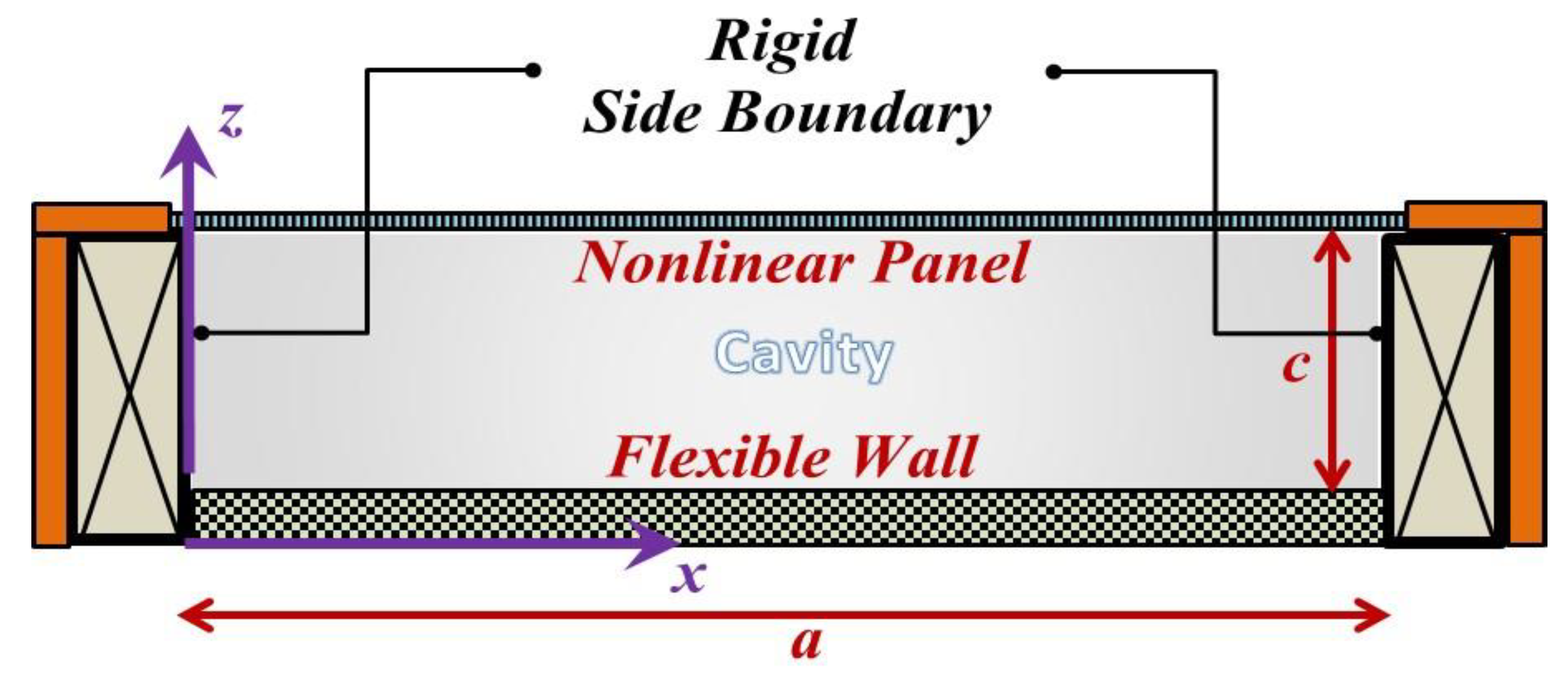
Figure 1 shows a flexible wall mounted with a symmetric panel absorber, which consists of a nonlinear panel and a cavity. It is assumed that the panel absorber and flexible wall are simply supported. According to [
10,
11], the governing equations of the nonlinear symmetric panel and flexible wall are shown in the following,
where
A and
B are the vibration responses of the nonlinear symmetric panel and flexible wall subject to the normalized acoustic pressures
Pc and
Po, respectively.
Pc and
Po depend on
A and
B. Thus, Equations (1) and (2) are coupled (the derivations of
Pc and
Po are shown in the next section);
ωc, ωo, ϼc and ϼo are the linear resonant frequencies and surface densities of the nonlinear symmetric panel and flexible wall, respectively;
is the nonlinear symmetric panel (
m and n are the mode numbers of the panel absorber;
a is the panel width;
γ is aspect ratio;
τc is panel thickness;
E is Young’s modulus;
ν is Poisson’s ratio;
t is time.
Note that the flexible wall is thick and vibrating linearly. Thus, its governing equation in Equation (2) is also linear.
Rewriting Equations (1) and (2) by changing
A and
B to
and
gives the following equations
where
is the approximate solution form of the Duffing equation (see below),
; ;
Φ and κ are the elliptical integral and its modulus, respectively;
is the initial vibration amplitude and is an unknown constant to be determined;
is the approximate solution form of the linearly vibrating flexible wall;
is the vibration amplitude of the flexible wall.
Note that
and
are not the exact solution forms. Thus, the residual terms,
and
, are considered on the right side of Equations (3) and (4).
ω is the nonlinear resonant frequency of the whole structural acoustic system and given by [
11]
where
T = 2
π/
ω is the period.
Equations (3) and (4) can be rewritten as
By setting an initial vibration amplitude for the nonlinear symmetric panel and solving the following weighted two residual equations, the unknown constant
can be found. Then, the nonlinear resonant frequency (i.e.,
ω) can be found using Equation (5)
where
and
are the weighting functions. In this study,
and
are set as
.
Pc and
Po depend on
ω,
and
(or
and
)
, and so do the residuals in Equations (6)–(9). Therefore, Equations (8) and (9) are coupled. By assigning a fixed vale to
as the initial vibration amplitude,
and
in Equations (8) and (9) can be found using the Mathcad equation solver (i.e., two equations, two unknowns). Note that the derivations of
Pc and
Po are shown in the next section.
3. Theoretical Formulation (Acoustic Part)
In this section, the derivations of the two normalized acoustic pressures (i.e.,
Pc and
Po in Equations (1) and (2)) are shown and described. Firstly, with reference to the 3-dimensional homogeneous wave equation [
10,
11,
12,
20]:
where
Ca is the speed of sound;
P(
x,y,z,t) is the acoustic pressure within the cavity at a position of (
x,y,z), which can be expressed as a summation of its harmonic components
where
is the
hth harmonic component of
P;
H is the number of harmonic components considered. Note that each
can also satisfy the 3-dimensional homogeneous wave equation.
The general solution form of the homogeneous wave equation is given by
where
;
a and b are the length and width of the cavity;
u and v are the acoustic mode numbers;
U and V are the numbers of modes used.
is the acoustic pressure mode shape function;
and are the constants depending on the boundary conditions.
Consider the boundary conditions at
x = 0,
a and
y = 0,
bFrom the above boundary conditions, it can be inferred that the suitable acoustic mode shape is a double cosine function.
From this we can use the following two boundary conditions and the general solution form in Equation (12) to obtain the normalized acoustic pressures at
z = 0 and
c (i.e.,
Pc and
Po)
where
is air density;
c is cavity depth. Note that there is only the fundamental harmonic component at
z = 0. This is because the flexible wall vibration is linear.
From Equations (12), (16) and (17), the normalized acoustic pressures can be given by
where
= the
hth harmonic component of
(i.e.,
);
Coupled stiffness at z = c, ;
Coupled stiffness at z = 0, ;
Coupling factor between nonlinear panel and cavity modes, ;
Coupling factor of cavity modes, ;
Coupling factor of panel modes,
Coupling factor between flexible wall and cavity modes, ;
Nonlinear panel mode function, ;
Flexible wall mode shape, (i.e., m = n = 1).
This is because the flexible wall is thick, and its fundamental resonant frequency is much higher than that of the thin panel absorber.
4. Results and Discussion
Table 1 shows the material properties, physical dimensions and other input parameters in the numerical cases in this study.
Table 2 and
Table 3 show the mode convergences for the center pressures at
z = 0 and
c induced by the nonlinear panel and flexible wall, respectively. In the convergence studies, two harmonic terms are adopted. The center pressures obtained from the 16-mode approach are normalized as one. It can be seen in the center pressures induced by the nonlinear panel that there are more modes required for good convergence if the cavity depth is longer. Generally, the nine acoustic mode approach is good enough for the ratio of a cavity depth to panel width of less than 1. The center pressure induced by the linearly vibrating flexible wall makes it much easier to find the convergence.
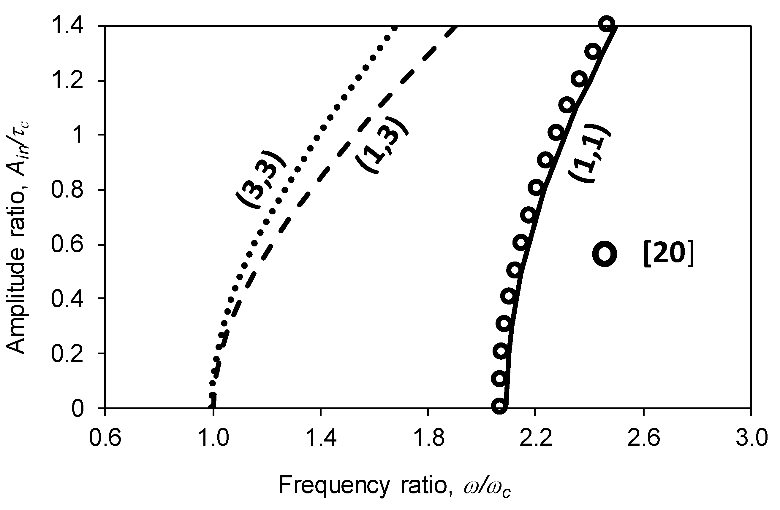
Figure 2 shows the amplitude ratio of the nonlinear symmetric panel plotted against the frequency ratio for various panel resonances. Note that the wall is rigid. Obviously, the first three frequency ratios are monotonically increasing with the amplitude ratio. The first resonant frequency ratio (the solid line) is compared with a set of circles obtained from [
20]. The first resonant frequency ratios obtained from the proposed method and the finite element method agree reasonably well with each other. When the amplitude ratio = 0, the higher mode resonant frequency ratios (i.e., (1,3) and (3,3) modes) are close to one, and the first resonant frequency ratio is much higher. It is implied that the higher mode resonant frequencies are not significantly affected by the air cavity stiffness. The slope of the solid line is deeper than those of the dashed and dotted lines, which represent the (1,3) and (3,3) mode frequency ratios. This implies that the higher mode resonant frequency ratios are more sensitive to the vibration amplitude.
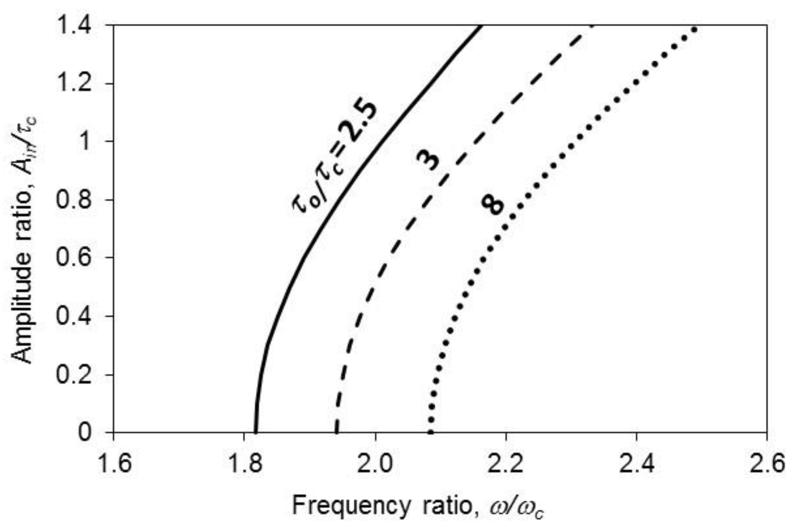
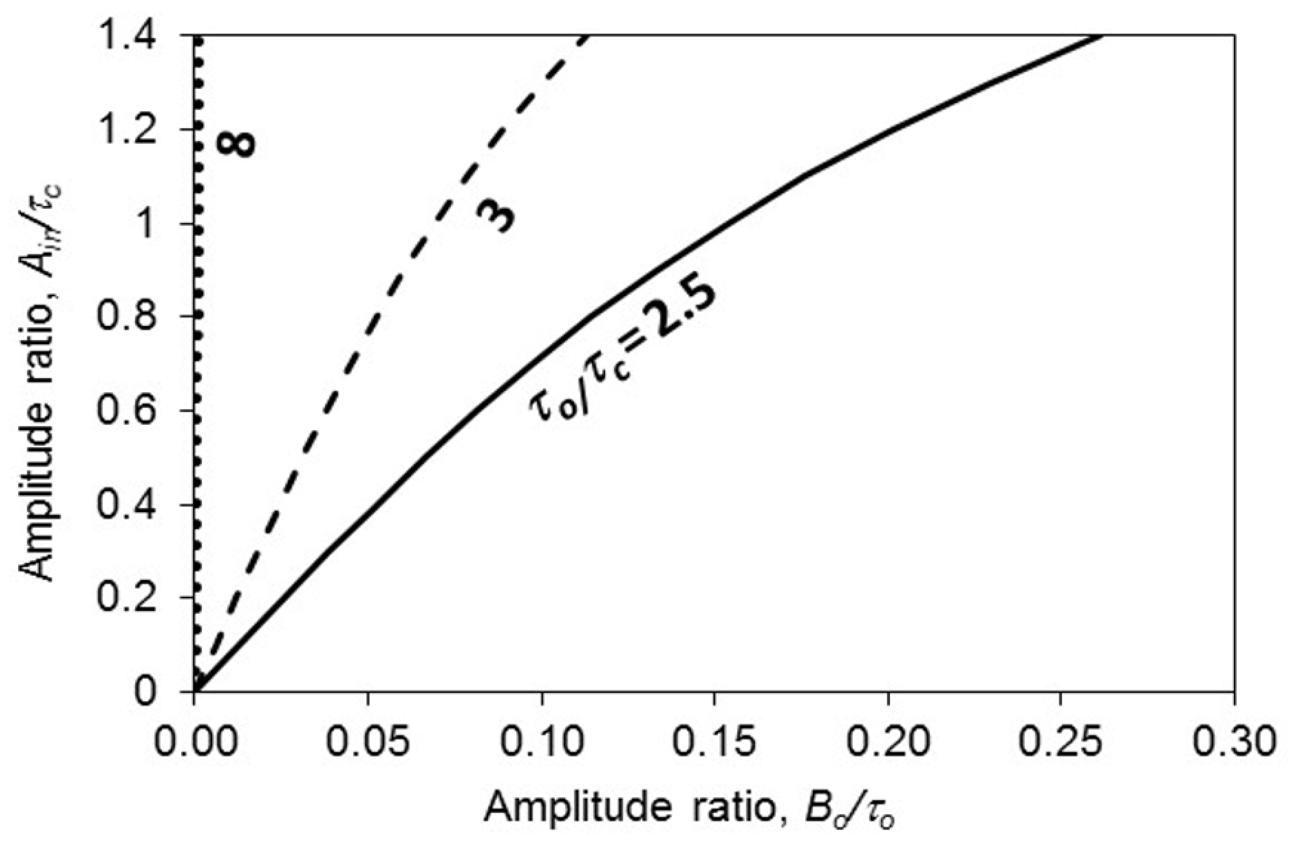
Figure 3 shows the amplitude ratio plotted against the first resonant frequency ratio for various thickness ratios (i.e., the ratio of wall thickness to nonlinear panel thickness,
τo/
τc). Note that the nonlinear symmetric panel thickness is kept unchanged. When the wall is thicker, the overall cavity stiffness is stronger. This explains why the line of
τo/
τc = 8 is the farthest to the right. This implies that the resonant frequency and the stiffness in this case are the highest among them. Interestingly, all these lines look quite parallel to each other. For
Ain/
τc = 0, the frequency ratio difference between the cases of
τo/
τc = 2.5 and 8 is about 7.2%; for
Ain/
τc = 1.4, the frequency ratio difference between the cases of
τo/
τc = 2.5; 8 is also about 7.2%.
Figure 4 shows the nonlinear panel amplitude ratio plotted against the flexible wall amplitude ratio for various thickness ratios. All of the ratios monotonically increase. The line of
τo/
τc = 8 is almost vertical. This implies that the wall vibration amplitude is inert to the nonlinear vibration amplitude. Comparatively, the wall stiffness is much stronger than the nonlinear panel stiffness, and it can be considered as nearly rigid. Hence, the ratio of wall amplitude to nonlinear panel amplitude is very small. An example of this is the line of
τo/
τc = 3, when
Ain/τc = 1,
Bo/τo = 0.0691. All lines in
Figure 4 are nearly linear, particularly for the cases with a high
τo/
τc ratio. In the cases of
τo/
τc = 3 and 2.5, the lines are slightly curved when
Ain/τc > 1.
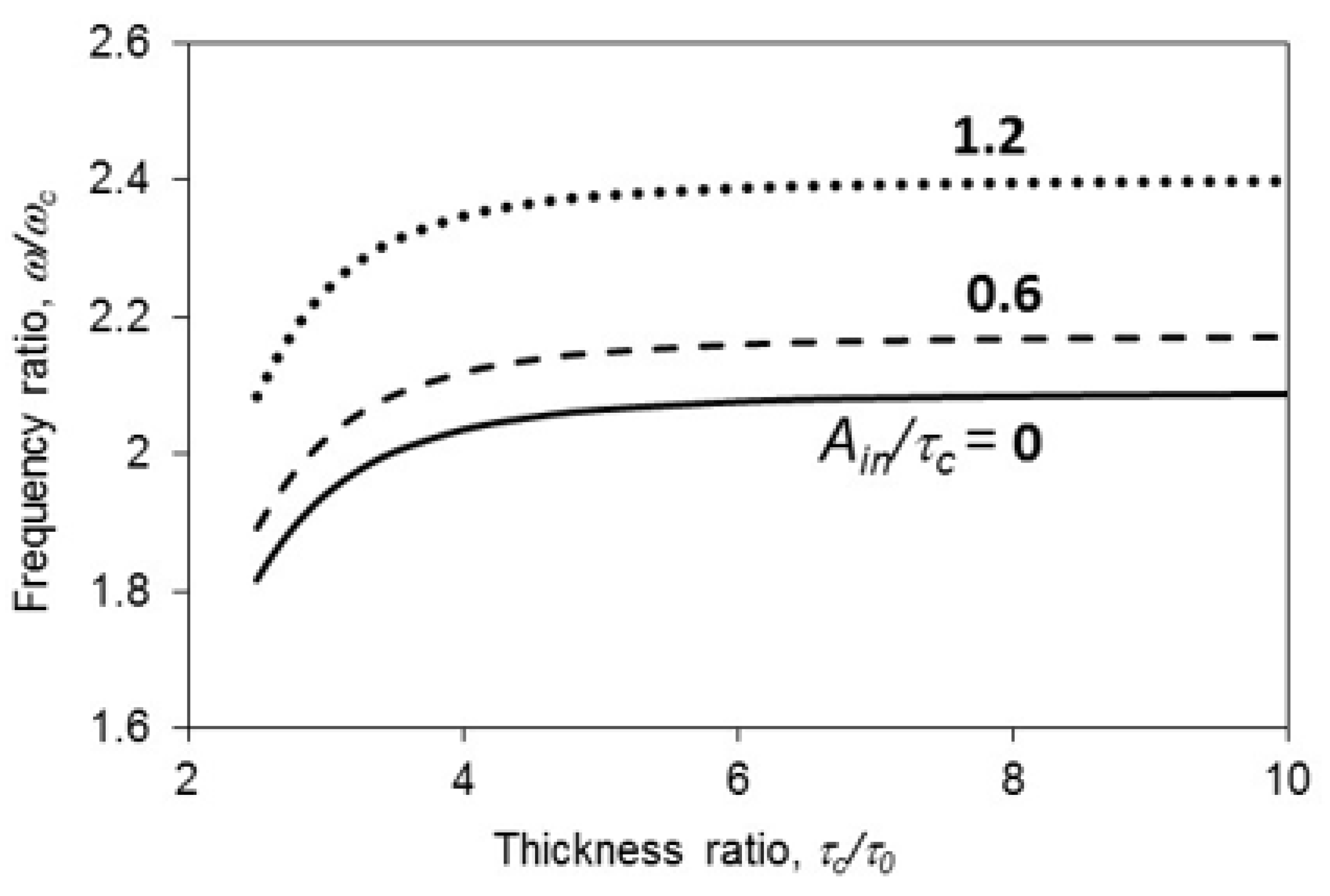
Figure 5 shows the first resonant frequency ratio plotted against the thickness ratio for various amplitude ratios. The frequency ratio in the case of the highest
Ain/τc is always higher than those of the other two cases because the highest ratio of
Ain/τc represents the highest stiffness. When
τo/
τc > 5, the three lines are almost horizontal. This implies that the wall is stiff when the ratio of
τo/
τc = 5. There is not much change even after the ratio of
τo/
τc further increases.
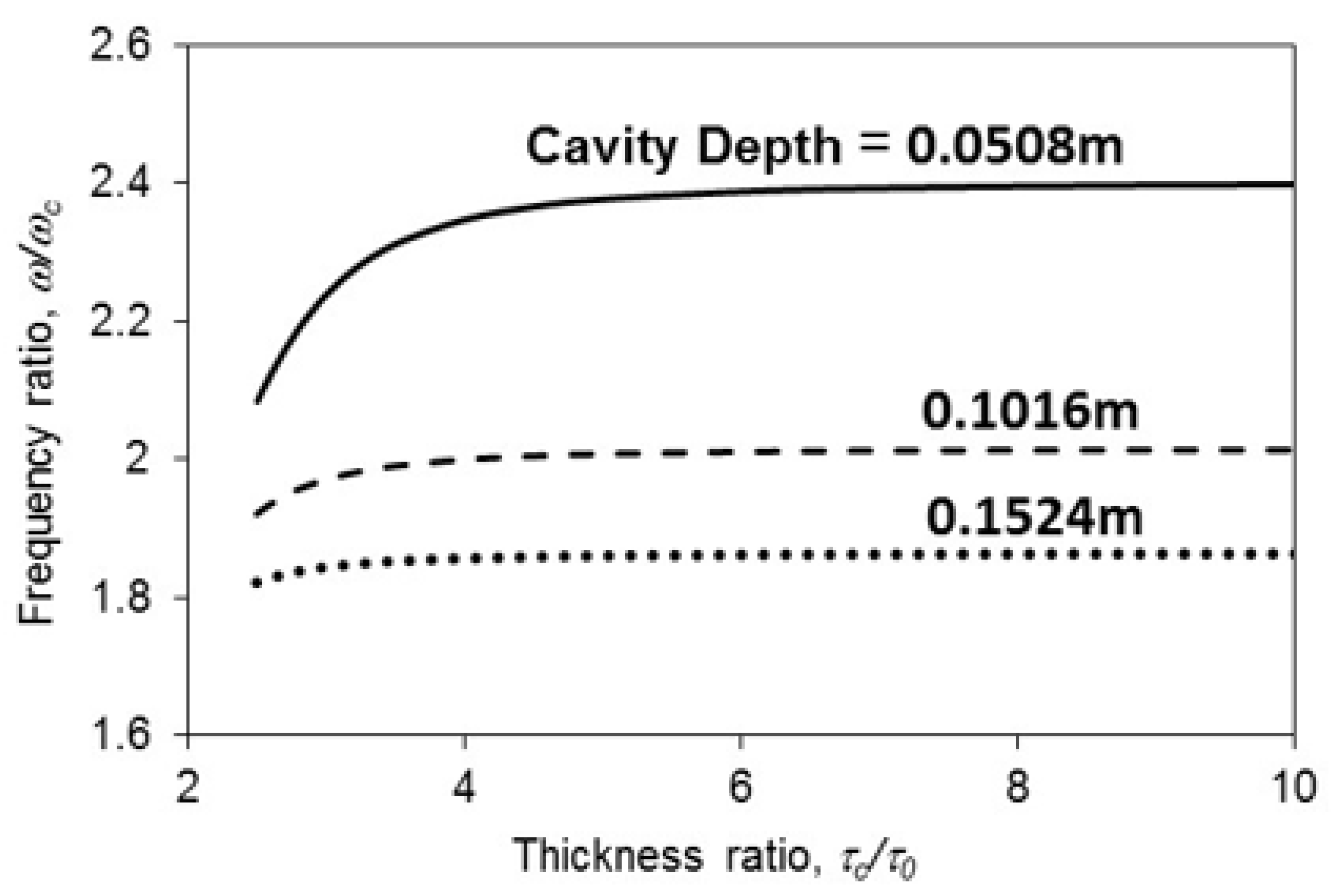
Figure 6 shows the first resonant frequency ratio plotted against the thickness ratio for various cavity depths. The frequency ratio in the case of the shortest cavity depth is always higher than those in the other two cases. This is because the cavity with the shortest depth is the stiffest. Similar to those in
Figure 5, the three lines in
Figure 6 are almost horizontal when
τo/
τc > 5. Unlike those in
Figure 5, the lines of cavity depths = 0.1524 m and 0.1016 m are insensitive to the ratio of
τo/
τ for almost the entire range. Only the line of cavity depth = 0.0508 m is sensitive to the ratio of
τo/
τ when it is less than 3.
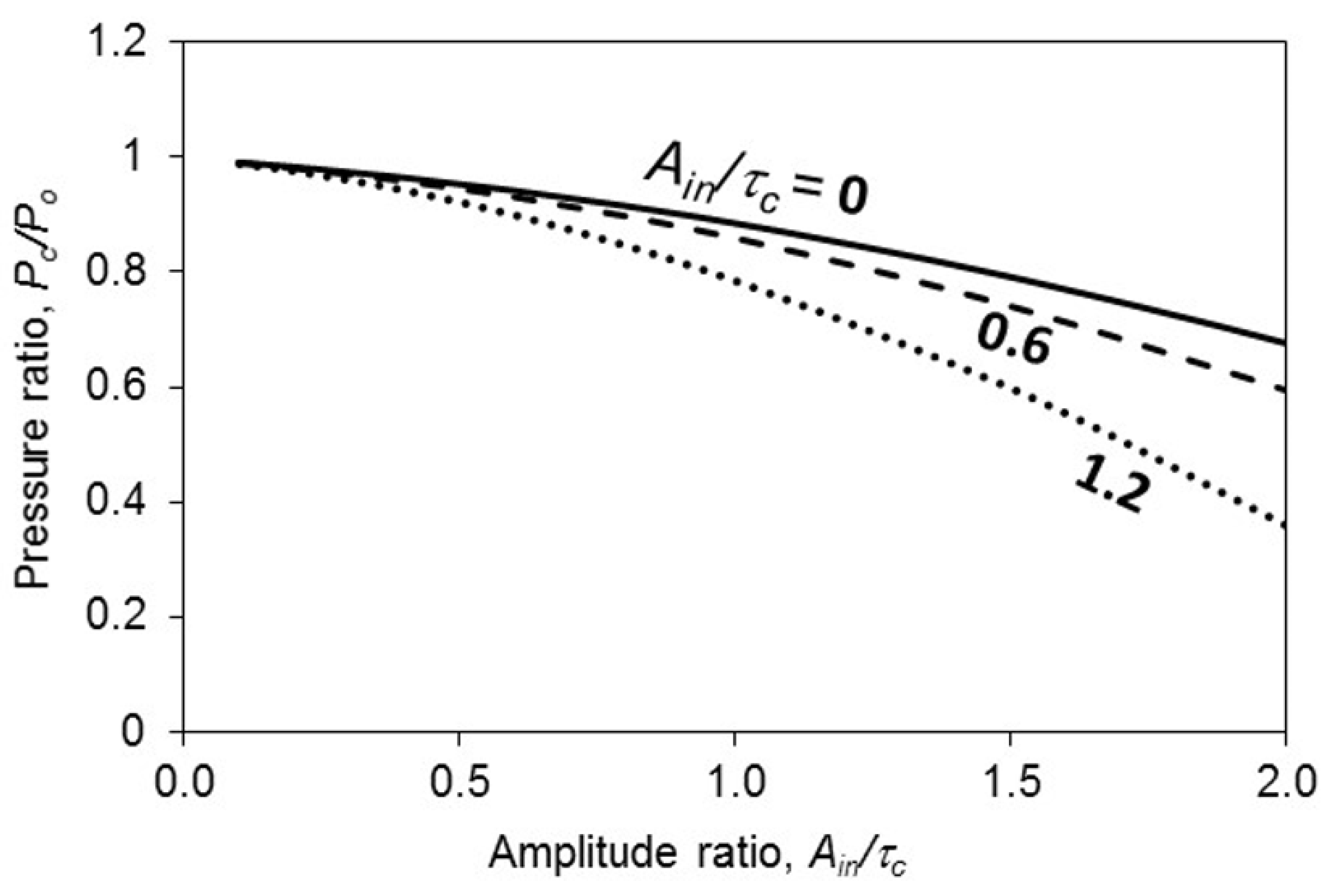
Figure 7 shows the center pressure ratio plotted against the cavity depth ratio for various amplitude ratios. The three lines are monotonically decreasing. When the cavity depth is short (e.g.,
c = 0.1 m), the three center pressure ratios are almost the same. When the cavity depth increases in length, the three lines deviate from each other. In the linear case and the most nonlinear case (i.e., the amplitude ratios = 0 and 1.2), the pressure ratios are always the highest and lowest for the entire range, respectively. The higher pressure ratio implies that the pressure at
z = c transmitted to
z = 0 is smaller (lower transmission loss).
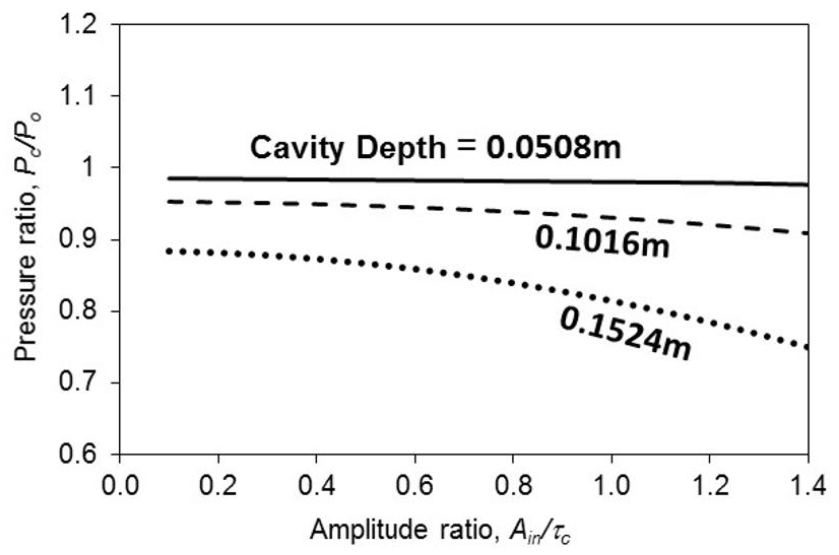
Figure 8 shows the center pressure ratio plotted against the amplitude ratio for various cavity depth ratios. Unlike those in
Figure 7, only the line with the longest cavity depth in
Figure 8 is monotonically decreasing. The other two lines are almost horizontal, or the two center pressure ratios are inert to the amplitude ratio. This implies that the ratio of the pressure at
z = c transmitted to
z = 0 is almost constant. In the case of the longest cavity depth, the cavity stiffness is the weakest so that overall cavity stiffness is sensitive to nonlinear stiffness, and it can significantly affect the pressure transmission ratio.
5. Conclusions
This study has presented the formulations for a nonlinear symmetric panel absorber mounted on a flexible wall, and has developed the frequency–amplitude relationship. This structural–acoustic problem considers the nonlinear and linear vibrations coupled with the multi-mode acoustic pressures within a cavity. The results of nonlinear resonant frequency and acoustic pressure are obtained using the weighted residual method and elliptic integral solution form. The results obtained from the proposed method and finite element method agree reasonably well with each other. The numerical simulations show that (1) the flexible wall can soften the overall cavity stiffness to make the resonant frequency lower, even though the wall vibration amplitude is much smaller than the nonlinear panel vibration amplitude; (2) when the thickness ratio of τo/τc = 5, the wall can be considered as very stiff or rigid. The frequency ratio changes very little even though the ratio of τo/τc further increases; and (3) when the cavity depth is long (e.g., 0.3024 m), the cavity stiffness is weak so that it is sensitive to the nonlinear stiffness induced by the large amplitude vibrations, and able to affect the pressure transmission ratio significantly.
As aforementioned, when the vibration amplitude of a panel is larger, the resonant frequency or panel stiffness is higher. In a typical linear design, it is assumed that the panel stiffness is constant and does not depend on the vibration amplitude. Thus, it would result in overdesign, especially for cases of large excitation or large vibration amplitude. This frequency–amplitude work can be a reference for a nonlinear panel absorber design.


