Article

A Method for Designing and Optimizing the Electrical Parameters of Dynamic Tuning Passive Filter

1
School of information Science and Engineering, Wuhan University of Science and Technology, Wuhan 430081, China
2
School of Electrical and Mechanical Engineering, Pingdingshan University, Pingdingshan 467036, China
3
School of Automation, Wuhan University of Technology, Wuhan 430070, China
*
Author to whom correspondence should be addressed.
Symmetry 2021, 13(7), 1115; https://doi.org/10.3390/sym13071115
Submission received: 3 June 2021 / Revised: 19 June 2021 / Accepted: 21 June 2021 / Published: 23 June 2021
(This article belongs to the Special Issue Meta-Heuristics for Manufacturing Systems Optimization)

Abstract

:
Power electronics-based apparatuses absorb non-sinusoidal currents. These are considered non-linear and non-symmetrical loads for the power grid, and they generate a harmonic current. The dynamic tuning passive filter (DTPF) is one of the best solutions for improving power quality and filtering out harmonic currents to get a symmetrical current waveform. The electrical parameters of DTPF can influence its absorbing harmonic current, tuning performance, and cost. In this paper, a method for designing and optimizing the electrical parameters of dynamic tuning passive filter is proposed in order to improve the effectiveness of DTPF and the symmetry level of the power source. First, according to the characteristics of the harmonic source, the design technical indicators of DTPF, and its topology, the design procedure for the electrical parameters of DTPF is proposed. Second, based on detailed analysis of the test results, the range of the harmonic current absorption coefficient is determined. Third, the range of the relationship coefficient is determined by analyzing the impact of the filter capacitor’s capacity on the filter performance. Fourth, the calculation method for the electrical parameters of DTPF is devised. Finally, the validity of this method is verified by several engineering cases, and the electrical parameters of the filter capacitor and electromagnetic coupling reactance converter (ECRC) under the lowest total cost are simulated and optimized. Our approach can optimize the electrical parameters of DTPF and improve the harmonic suppression effectiveness, thus leading to a more symmetrical waveform and successfully avoiding power grid problems. The research results of this study not only provide a basis for the design of ECRC, but also lay a foundation for the machining DTPF.

1. Introduction

To date, power electronics have been extensively applied to numerous fields, such as industrial manufacturing, microgrids, transportation systems, distributed generation interfacing converters, and handheld devices. Power electronics-based apparatuses absorb non-sinusoidal currents. These are considered non-linear and non-symmetrical loads for the power grid, and they generate harmonic current, which is of vital significance for the improvement of the power quality in contemporary society. Its occurrence may result in conductor overheating, voltage distortion, transformer malfunctions, unnecessary protection device trips, and interference in the telecommunication network [1,2,3,4,5,6,7].
Recent years have witnessed in-depth investigation of the causes, hazards, inhibition strategies, and related technologies concerning harmonics. One of the best solutions for improving power quality and compensating harmonic currents to get a symmetrical waveform is to install a power filter at the point closest to the harmonic source. In order to eliminate the harmonic disturbance, three kinds of filters were researched, including passive power filter (PPF), active power filter (APF), and hybrid active power filter (HAPF). Each of them has their own advantages and disadvantages, and are all suitable for different occasions.
The passive power filter (PPF) is, in comparison to other techniques, the most popular method for harmonic limination, due to its robust, simple design, low cost, and maintenance-free operation. PPF can also act as reactive power compensation to the system, thereby being capable of improving the power factor and reducing losses, simultaneously. However, parameter variation brought about by aging or temperature could deteriorate the filtering features of PPF. Moreover, the design of its parameters is a nonlinear mixed integer programming problem with various constraints. Conventionally, its key parameters are determined by experience, based on a single technical index or economic index. This inevitably elicits heavy dependence on subjective experience, thus making it difficult to satisfy a number of requirements. The results are affected by the power source impedance, which tends to trigger series resonance and parallel resonance [8]. Inspired by the nature of PPF, many researchers have explored effective ways to solve relevant problems, including the enhanced bacterial foraging optimization (EBFO) algorithm [9], fractional-order quaternion-valued neural networks with neutral delays and external disturbance [10], a differential evolution algorithm [11], an analytical method for calculation [12], and a multi-objective optimization algorithm [13,14]. In particular, the conservative power theory has been proposed to evaluate parameters associating with product quality, aiming to obtain subsidies for the design of tuned passive filters through focusing on the reduction of harmonic distortion indices regarding voltage and current. It can also contribute to the reactive compensation of the electrical system under research. Nevertheless, engineers might face some challenges while designing PPF, as various measurements, conditions, and practical standards need to be be taken into careful account. Inconvenience will emerge when these issues make PPF unable to maintain the system’s operation within acceptable power quality for which a solution must be put forward [15,16,17,18].
PPF (e.g., single-tuned) should be tuned to a frequency slightly lower than that of the harmonic to be eliminated because the aging of their elements (LC), atmospheric conditions, or fault can cause a change in the initial tuning frequency of the PPF. This tuning frequency should be chosen in consideration of the equivalent harmonic impedance of the power grid to be eliminated, which should be smaller than that of the PPF [19]. The harmonic to be eliminated should be a specific load characteristic harmonic (or electrical system characteristic harmonic) after the fundamental harmonic. A bad choice in the PPF resonance frequency can cause the amplification of harmonics at the electrical grid side and filter terminals [20].
The defects of PPF have urged researchers to seek other alternatives, among which APF has obtained wide attention as a type of power electronic that can suppress harmonics dynamically. However, its application in harmonic suppression of large capacity fields is limited because its direct carrying of the power fundamental voltage and current requires a larger capacity converter [21,22]. In view of this drawback, HAPF was devised, based on PPF and APF [23]. However, in terms of the entire filter system, which employs either a merely passive power filter or hybrid power filter, it is of vital significance to reasonably design the parameters of the PPF [24].
Could the strengths of PPF and APF be combined? A theoretical and experimental comparison between the different THD indexes were presented [25]. The controlled modulate power filters (MPF) were introduced inside a microgrid. It has the advantages of adjusting the voltage distribution, having proficient energy use, upgrading the control scheme, and improving the power quality [9]. The dynamic tuning passive filter (DTPF) was accordingly proposed by the authors [26,27,28,29,30,31]. Its principle is based on a novel electromagnetic coupling reactance converter (ECRC). The primary reactance winding of the ECRC is connected in series with a filter capacitor, and the secondary winding of the ECRC is connected a power electronic impedance converter (PEIC). The developed ECRC is featured by electromagnetic coupling and adjustable inductance, which facilitate the realization of continuous parameter adjustment and dynamic DTPF tuning. DTPF is characterized by the strengths of its harmonic suppression and energy saving quality. With the minimum offset of a certain fundamental harmonic current as the control target, the inductance of ECRC is adjusted for the resonance branch to constantly satisfy the resonance condition and absorb the harmonic current to a given value. DTPF, featured by high reliability, a simple structure, large capacity, and low cost, is capable of meeting new requirements for power quality, and thus, is widely utilized in industry and transportation.
ECRC electrical parameters mainly include the inductance ( L n 1 ), the rated current ( I L n 1 ) and apparent power ( S N ) of the ECRC primary reactance winding. The electrical parameter of the filter capacitor is its capacity ( Q C s ). In this study, it is found that these electrical parameters of DTPF mainly affected the absorbing harmonic current ( I f ), tuning performance and cost of DTPF. The larger the I f , the larger the Q C s of the filter capacitor; the larger the S N , the higher the cost of DTPF. Based on the resonance condition, L n 1 under main frequency f h of harmonic current is calculated. Furthermore, the inductance adjustment range of the ECRC affects the tuning performance of DTPF; the larger the value, the better the tuning performance. In addition, the electrical parameters corresponding to the lowest total cost are the basis of the machining ECRC.
Therefore, a method for designing and optimizing the electrical parameters of dynamic tuning passive filter is proposed in this paper. The major contributions of the current study lie in (1) the design procedure for the electrical parameters of the DTPF, (2) the design method and optimization of filter capacitor’s capacity and rated parameters of ECRC to comply with their technical indicators, and (3) the investigation on the best electrical parameter. The rest of the paper is presented in the following order. The topological structure of a DTPF, filter performance evaluation indices, and implementation procedures are considered in Section 2. In Section 3, based on detailed analysis of the test results, the range of the harmonic current absorption coefficient is determined. The range of the relationship coefficient is also determined by analyzing the impact of the filter capacitor capacity on the DTPF performance. Section 4 advances the implementation of the design method for the electrical parameters of DTPF. Section 5 proposes a genetic optimizing method of the electrical parameters of DTPF and develops a genetic optimization simulation system. Section 6 verifies the effectiveness and the symmetry level of the proposed design method by several engineering cases. The relationship model between electrical parameters and harmonic current is also built in this section, based on which the cost and parameters of DTPF can be estimated rapidly. Finally, the discussion and suggestions for future studies are presented.

2. Principle of Design Method

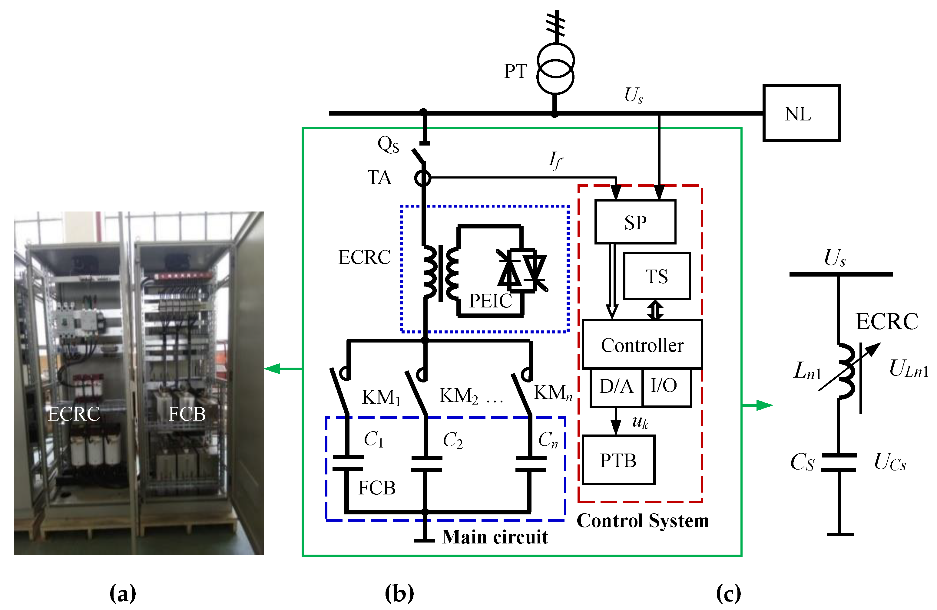
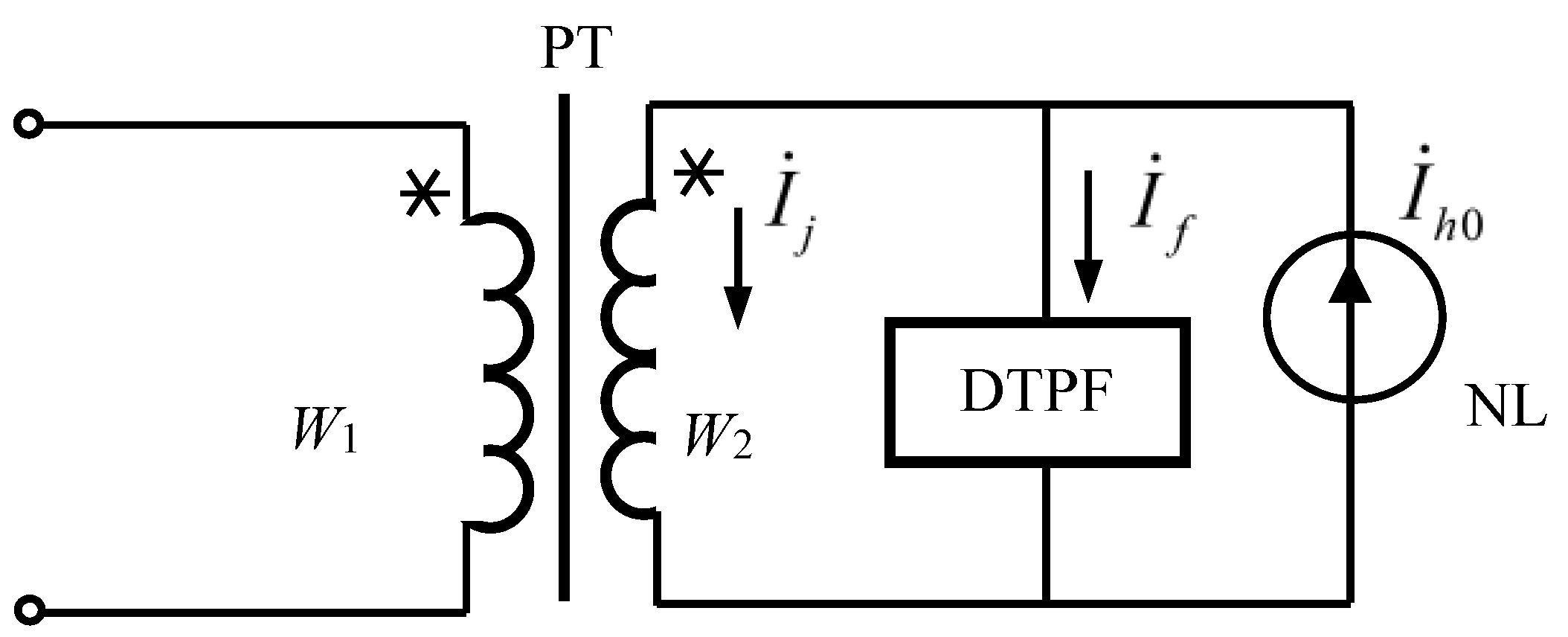
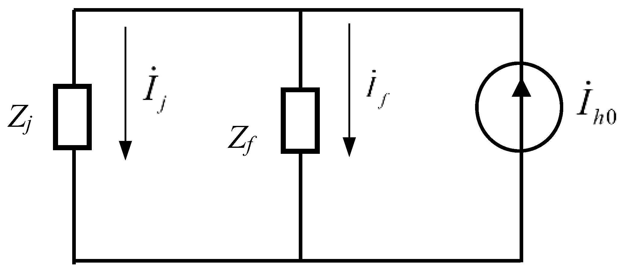
2.1. Topological Structure of a DTPF

As the key component of DTPF, ECRC is a reactor with variable impedance and adjustable inductance. The primary reactance winding of the ECRC is connected in series with a filter capacitor bank (FCB), while its secondary winding is connected to a power electronic impedance converter (PEIC). Taking a single DTPF as an instance, its photograph, block diagram, and simplified topology are shown in Figure 1.
In Figure 1, Q s is a circuit breaker, KM 1 – KM n are AC contactors, C s is the equivalent capacitance value of FCB, L n 1 is the equivalent inductance of ECRC, L n 1 and C s form a series resonance branch, and U s , U L n 1 , and U C s are the voltage of power supply, the terminal voltage of ECRC, and the terminal voltage of FCB, respectively. In addition, NL is a nonlinear load and also a harmonic source. PEIC is the power electronic impedance converter. The mechanism and control structure of DTPF are illustrated in [26,27].
The systematic structure of DTPF is comprised of two parts, namely, a control system and a main circuit, which consists primarily of Q s , ECRC, FCB and KM 1 – KM n . The PEIC is composed of the reactance control winding as well as six thyristors from V1 to V6 driven through phase control. In accordance with the control principle of the power electronic conversion technology, A–B, A–C, B–C, B–A, C–A and C–B correspond to thyristors V 1 , V 3 , V 5 , V 4 , V 6 and V 2 , respectively. For the purpose of achieving the impedance transformation of the three-phase high impedance inverter, a pair of thyristors needs to be triggered every 60 degrees.
The control system includes a harmonic sensor (SP), a controller, a thyristor pulse trigger board (PTB), a touch screen (TS), a D/A converter (D/A), a digital input and output (I/O), etc. Information related to harmonics is gathered by the system through SP; control decisions, including data processing and filtering algorithm optimization, are made by the controller. There are two ways to output the results. The first is D/A, which controls the PEIC through PTB achieves the transformation and continuous control of the electromagnetic parameters of the ECRC. The second is I/O, which controls the dynamic switching of the FCB in the main circuit. These are the two methods used by the controller to control the signal output for the purpose of tuning and filtering the harmonic current.

2.2. Filter Performance Evaluation Indices

The performance evaluation indices of DTPF are presented to evaluate its filtering performance, efficiency, and energy-saving effect.
Let I s 0 , I h 0 and cos θ 0 represent the current RMS, the h-th harmonic current, and power factor at the test point of harmonic source without DTPF, respectively, whereas I s 1 , I h 1 and cos θ 1 represent the current RMS, the h-th harmonic current and power factor at the test point of the harmonic source with DTPF. I S D denotes the design value of the harmonic current absorbed by DTPF.
  • Harmonic current absorption rate:
The harmonic current absorption rate of DTPF equals the ratio of I h 0 I h 1 to I h 0 . It can be expressed as follows:
K x s = I h 0 I h 1 I h 0 × 100 %
This rate reflects the impact of DTPF on filtering the harmonic current, and the filtering performance can be improved with the increase in its value.
  • Filter efficiency:
The filter efficiency equals the ratio of I h 0 I h 1 to I S D . It can be expressed as follows:
K x l = I h 0 I h 1 I S D × 100 % ,
The filter efficiency signifies the degree to which DTPF reaches the design value, and a larger value is more conducive to the filter efficiency.
  • Current RMS decrease rate and power factor increase rate:
The current RMS decrease rate equals the ratio of I s 0 I s 1 to I s 0 . It can be expressed as follows:
K I R = I s 0 I s 1 I s 0 × 100 % ,
The power factor increase rate equals the ratio of cos θ 1 cos θ 0 to cos θ 0 . It can be expressed as follows:
K P H = cos θ 1 cos θ 0 cos θ 0 × 100 % ,
The above two rates reflect the energy-saving effect of DTPF with larger rates generating a better energy-saving effect.

2.3. Implementation Procedures of Design Method

In the design of DTPF, the problem of the harmonic current absorption coefficient ( K s h ) must be considered, which is directly related to the selection of the filter capacitor value. A higher K s h requires a greater capacitor value. So, K s h is one of the design technical indicators of DTPF.
Definition: The h-th harmonic current absorption coefficient K s h of DTPF equals the ratio of the h-th harmonic current absorbed by DTPF ( I f ) to the h-th harmonic current of the harmonic source ( I h 0 ). K s h can represent and verify the design ability of DTPF to absorb harmonic currents and is a prerequisite for designing the electrical parameters of the DTPF. Its value can be calculated by the following:
K s h = I f I h 0 ,
Definition: The relationship coefficient is defined as the ratio of the filter capacitor’s capacity Q C s to I f , denoted by K s , and its value can be calculated by the following:
K s = Q C s I f ,
K s represents the quantitative correlation between the harmonic current absorption value and the capacity of the filter capacitor.
According to the characteristics of the harmonic source, the design technical indicators of DTPF include the current, voltage and the harmonic order of the harmonic source, K s h and K s . The design method for the electrical parameters of DTPF is proposed in this paper, and its implementation procedures are as follows:
  • Step 1: By analyzing the expression of the h-th harmonic current absorption coefficient, the value range of K s h is determined;
  • Step 2: Through experimental research, the relationship between the current absorbed by DTPF and the filter capacitor’s capacity is analyzed, and then the value range of the relationship coefficient K s can be determined;
  • Step 3: The design method of the filter capacitor’s capacity is proposed. According to the design value of the h-th harmonic current absorbed by DTPF ( I S D ), the harmonic current absorbed by DTPF ( I f ) is determined; then the filter capacitor’s capacity is designed, based on the relationship coefficient K s ;
  • Step 4: The design method of the rated parameters of ECRC is proposed. The inductance of the ECRC is calculated based on the resonance conditions and the engineering adjustment range. According to the harmonic current absorbed by DTPF ( I f ) and considering the engineering application requirements, the rated current and rated capacity of the ECRC are calculated.

3. Range of Absorption Coefficient and Relationship Coefficient

3.1. Range of Absorption Coefficient

The filter system consists of a power transformer (PT), the DTPF, and the nonlinear load (NL). Its equivalent circuit is shown in Figure 2.
Based on Figure 2, the steady-state harmonic model of the alternating current system can be obtained, as shown in Figure 3.
In Figure 2 and Figure 3, Z j and Z f are, respectively, the equivalent impedance of the secondary side of PT and DTPF; I ˙ h 0 , I ˙ f and I ˙ j are the h-th harmonic current of the harmonic source, the harmonic current absorbed by DTPF, and the harmonic current flowing into the secondary side of PT, respectively. The RMSs are expressed as follows:
I f = Z j Z f + Z j × I h 0 , I j = I h I f
The absorption coefficient of the h-th harmonic current obtained by Equation (8) is the following:
K s h = Z f Z f + Z j ,
where
Z j = R j + j X j , Z f = R f + j X f
The conclusions drawn from Equations (7) and (8) are as follows:
  • By adjusting K s h , the value of the h-th harmonic current absorbed (filtered) by DTPF can be altered. The larger the K s h , the larger the h-th harmonic current absorbed by DTPF, and the smaller the h-th harmonic current flowing into the power grid. By contrast, the smaller the K s h , the smaller the h-th harmonic current absorbed by DTPF, and the larger the h-th harmonic current injected into the power grid;
  • When K s h = 1, the h-th harmonic current injected into the power grid is 0, realizing the full tuning of DTPF.
In practical applications, K s h cannot be exactly equal to 1. Instead, its value is within the range of 0 to 1. The major reasons for the variation in the value of K s h are as follows:
  • The frequency of the power supply varies with the fluctuation in the nonlinear load;
  • The inherent harmonics and converted harmonics of the nonlinear load;
  • The larger the K s h , the greater the investment and the higher the cost.
In summary, the DTPF can achieve full tuning filtering theoretically, but in practical applications, this is infeasible. According to engineering experience, K s h is generally reasonable in the range of 0.6 to 0.8.

3.2. Range of Relationship Coefficient

In this study, the range of the relationship coefficient ( K s ) is determined by analyzing the impact of the filter capacitor’s capacity on the filter performance. On this basis, the capacity parameters of filter capacitor are designed.
For the purpose of testing the impact of the filter capacitor’s capacity on the filter performance, a DTPF test platform is constructed, according to Figure 1. The platform consists of a three-phase power supply system, a DTPF, and a harmonic generator. The schematic diagram of its composition is shown in Figure 4.
The harmonic generator is modified by an active power harmonic filter. It is mainly used to simulate harmonic sources to inject harmonic currents of different frequencies and magnitudes into the power grid. The DTPF is developed, according to the test requirements.
It is found from the field test that the 5-th harmonic current component generated by the common frequency converter and DC converter account for 70% of the whole harmonic current component. Hence, this current is determined as the object of harmonic filtering.
The following tests are performed on the DTPF test platform:
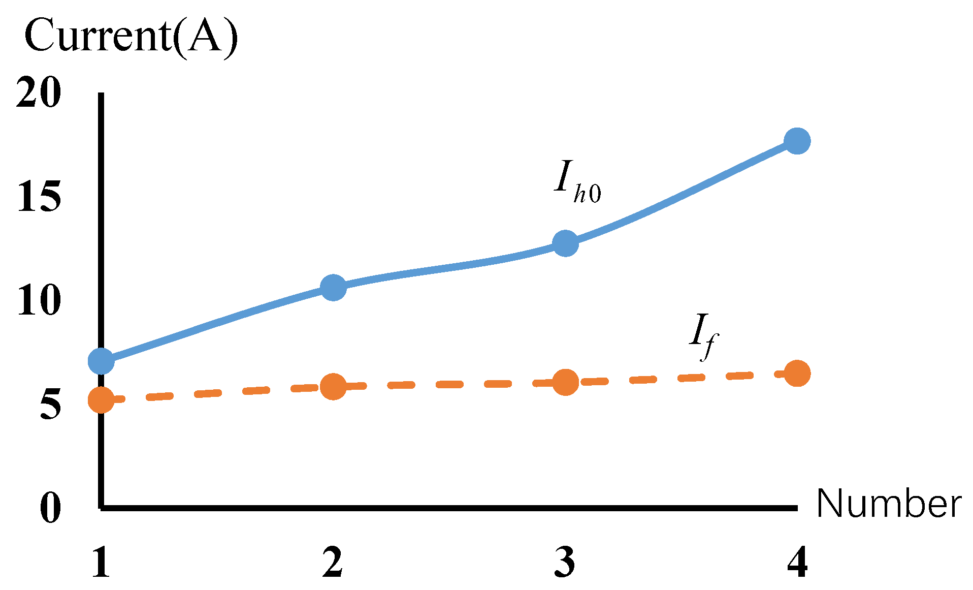
  • Test (I): The harmonic generator is used to inject 5-th harmonic currents of different magnitudes into the power grid with the capacity of the filter capacitor remaining unchanged. Then, the amount of the 5-th harmonic current absorbed by the DTPF is obtained through testing.
In this test, the capacity of the filter capacitor is set to 10 kVar, and four groups of 5-th harmonic currents ( I h 0 ) with magnitudes of 7.07 A, 10.6 A, 12.73 A, and 17.68 A are injected into the power grid of the test platform through the harmonic generator. Then, tests are conducted on DTPF to obtain the 5-th harmonic currents ( I f ) absorbed by the DTPF. The test results obtained from Test (I) are listed in Table 1.
In Table 1, I j represents the remaining 5-th harmonic current in the grid after filtering. Theoretically, the sum of the 5-th harmonic current ( I f ) absorbed by the DTPF and I j should be the 5-th harmonic current ( I h 0 ) that flows into the grid through the harmonic generator. Nevertheless, due to the influence of grid fluctuations or background harmonic currents, the sum of I f and I j is not equal to I h 0 in the test, and there is a small deviation. From Table 1, the broken lines of I h 0 and I f in the above four cases are obtained as shown in Figure 5.
Result analysis of Test (I):
  • Judging from Figure 5, under constant capacity of the filter capacitor, with the gradual increase in the 5-th harmonic current injected into the power grid, the 5-th harmonic current absorbed by the DTPF tends to be saturated (the 5-th harmonic current that the DTPF absorbed in this test is up to about 6.5 A);
  • For the same DTPF, under the condition that the harmonic frequency and the capacity of the filter capacitor stays constant, the amount of harmonic current absorbed by the DTPF basically remains unchanged.
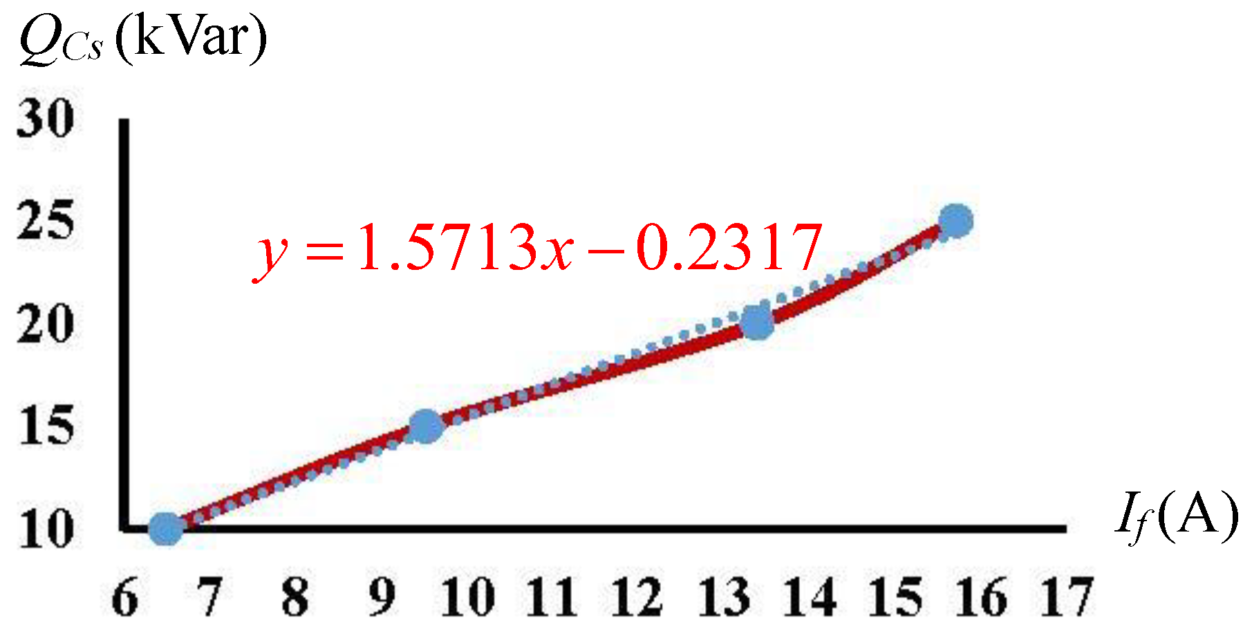
  • Test (II): The harmonic generator is utilized to inject the 5-th harmonic currents of the same magnitude into the power grid, after which the capacity of the filter capacitor is altered, so the magnitude of the 5-th harmonic current absorbed by the DTPF is obtained through test.
In this test, the capacity of the filter capacitor is set to 10 kVar, 15 kVar, 20 kVar and 25 kVar, respectively. The harmonic generator is used to inject the 5-th harmonic current with an magnitude of 17.68 A into the power grid, and then the capacity of the filter capacitor is changed to measure the 5-th harmonic current absorbed by DTPF.
The results obtained from Test (II) are given in Table 2.
By analyzing the test data in Table 2, the correlation between Q C s and I f can be obtained as shown in Figure 6.
The results of Test (II) show that under the condition that the harmonic current of the harmonic source remain unchanged, and the 5-th harmonic current absorbed by the DTPF increases with the rising capacity of the filter capacitor Q C s , thus generally showing a linear relationship. The corresponding relationship coefficient K s about 5-th harmonic currents ( I f ) is approximately 1.57.

4. Implementation of Design Method

4.1. Design of Filter Capacitor Parameters

According to the conclusions of Tests (I) and (II), it is very important to determine the filter capacitor’s capacity reasonably, and its capacity directly affects the magnitude of harmonic current absorbed by DTPF.
The calculation procedures of the filter capacitor’s capacity is as follows:
Step 1: According to K s h (generally 0.6–0.8) and the harmonic source current ( I h 0 ), the design value ( I S D ) of the harmonic current absorbed by DTPF is determined. Its calculation equation is as follows:
I S D = K s h × I h 0 ,
Step 2: With the relationship coefficient K s (usually 1.2–2.2) and I S D , the filter capacitor’s capacitance Q C s is determined, and the filter capacitor C s is calculated.
The capacity of the filter capacitor Q C s under the rated operational voltage U C s is calculated by the following:
Q C s = K s × I S D ± Δ Q , C s = Q C s 2 π f h U C s 2
where ± Δ Q is a fine adjustment of the filter capacitor. It ranges from 1 to 5 kVar, so that the value of Q C s is an integer multiple of 5, which is consistent with the rated parameters of the filter capacitors on the market. C s is the capacitor (uF) at the main frequency ( f h ) of the harmonic current.
The filter capacitor bank (FCB) is usually composed of several capacitors. For example, the capacities of low-voltage capacitors are generally 5 kVar, 10 kVar, 15 kVar, 20 kVar and 30 kVar, which can be connected in parallel to obtain a larger capacity.

4.2. Design of ECRC Parameters

ECRC parameters mainly include the inductance ( L n 1 ), the rated current ( I L n 1 ), and the rated apparent power ( S N L n 1 ) of the ECRC primary reactance winding.
Based on the resonance condition X n 1 = X C s and considering the engineering adjustment range, the inductance L n 1 under main frequency ( f h ) of harmonic current are calculated as follows:
L s = 10 9 ( 2 π f h ) 2 C s L n 1 = K 1 L s ,
where L s is the filter inductance that meets the series resonance, and K 1 is the selection coefficient. According to practical engineering experience, the value of K 1 ranges from 1.5 to 2.0. Therefore, in accordance with the engineering application requirements and the design value of the h-th harmonic current absorbed by DTPF ( I S D ) that was determined by Equation (10), the rated current of the ECRC primary reactance winding is calculated by the following:
I L n 1 = K 2 × I S D ,
where K 2 is the absorption current coefficient of the ECRC primary reactance winding. According to practical engineering experience, the value of K 2 ranges from 1.8 to 2.2.
The rated apparent power( S N L n 1 ) is calculated by the following:
S N L n 1 = 3 I L n 1 2 × ( 2 π f h L n 1 ) ,

5. Genetic Optimizing Method and Simulation System

Based on the global optimization capability of the genetic algorithm, a genetic optimizing method of the electrical parameters of DTPF is proposed, a genetic optimization simulation system is developed, and the main electrical parameters of the filter capacitor and ECRC are designed.
The genetic algorithm (GA) is a parallel, random and adaptive search algorithm developed from the natural selection and evolution mechanism of the biological world. Compared with the traditional search and optimization algorithm, the search points are parallel rather than single points, and only the objective function and the relative fitness function are needed without auxiliary information. At present, genetic algorithm is widely used in function optimization, combinatorial optimization, production scheduling, automatic control, image processing and other fields. However, there is still no effective quantitative analysis method in terms of algorithm accuracy and reliability. In addition, there are also shortcomings, such as inaccuracy of coding representation and premature convergence.
The DTPF parameter is optimized by the genetic algorithm because the initial investment cost of DTPF is nonlinear and nonconvex. The genetic algorithm is used to optimize the relationship coefficient K s (which is needed for calculating the capacity of the filter capacitor), as well as the selection coefficient K 1 and the absorption current coefficient K 2 (which are necessary for calculating the inductance and rated current of ECRC). Then, such parameters as Q C s , L n 1 and I L n 1 which corresponded to the lowest cost are obtained.
The genetic optimizing method in this paper is used for parameter optimization, which belongs to real number field, and the linear combination or convex combinationin [32,33] is used during recombination. The proposed procedure is convergent.

5.1. Optimization of Objective Function

The initial investment cost of DTPF is mainly composed of core components (filter capacitors and an ECRC), a cabinet, a control system, and auxiliary materials. The DTPF parameters are optimized by the core component cost F c c , and its minimum value is the optimization goal. F c c can be calculated by the following:
F c c = k L S N L n 1 + k c Q C s F m a x ,
where S N L n 1 and k L are the apparent power (kVA) and unit price factor of the ECRC, respectively; Q C s and k c are the capacity (kVar) and unit price factor of the filter capacitor bank, respectively; and F m a x is the upper limit of the initial investment cost.

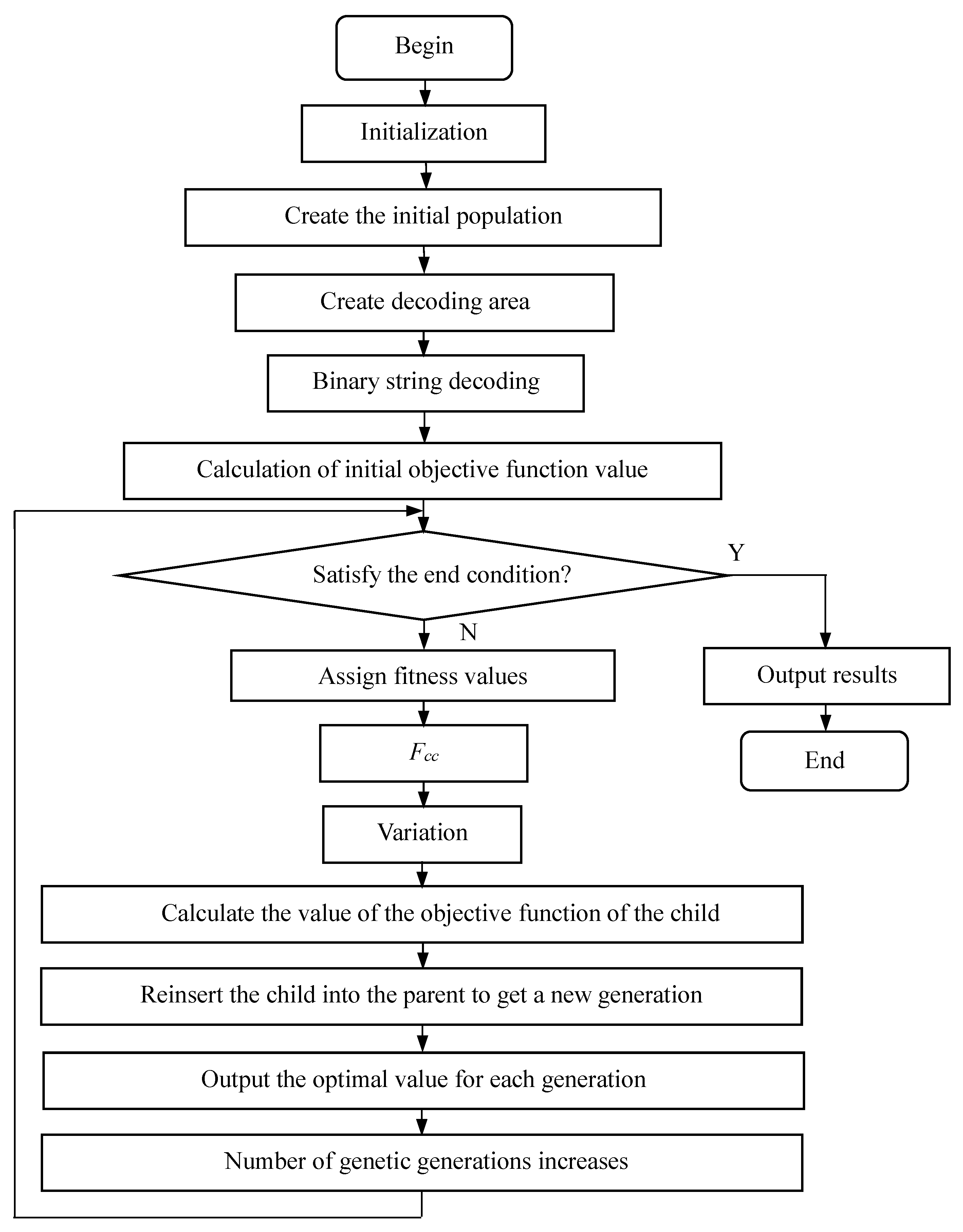
5.2. Optimization Steps of Electrical Parameters

The MATLAB genetic algorithm toolbox of Sheffield University is used to optimize the design of the electrical parameters of DTPF. The optimization design flow chart of the DTPF electrical parameters is shown in Figure 7.
The genetic optimization steps of DTPF parameters are as follows:
Step 1: Initialization
Parameters, such as the number of individuals (NIND), the maximum number of genetic generations (MAXGEN), the number of variables (NVAR), the precision of variables (PRECI), the generation gap (GGAP), the crossover rate (COP), and the mutation probability (MUP) are set. The generation counter is reset.
Step 2: Creation of initial population
According to MAXGEN, NVAR and PRECI, the “crtbp” function is called to create an initial population, Chrom, whose element is a random number. The size y s of Chrom is as follows:
y s = y n × y w × y b ,
where y n , y w and y b are the number of individuals, the dimension of the variable, and the precision of variables, respectively.
Step 3: Creation of decoding area
The decoding are consist of the upper and lower limits of the relationship coefficient K s , the upper and lower limits of the selection coefficient K 1 , and the upper and lower limits of the absorption current coefficient K 2 . The decoding area Field D = [ L e n ; L b ; U b ; C o d e s c a l e ] is created by setting the length L e n of the binary string, the lower limit L b and upper limit U b of the variables [ K s ; K 1 ; K 2 ] , and the “rep” function is called to set the decoding rules of the variables [ K s ; K 1 ; K 2 ] .
Step 4: Binary string decoding
The “bs2rv” function is called to decode the initial population Chrom so as to obtain the binary string “evlautestrum” of the initial population.
Step 5: Calculation of initial objective function value
First, the evaluation function “evlatuefuntion” is constructed, according to the objective function Equation (15). Subsequently, the “evlautestrum” and the parameters required for the objective function computation are substituted into the “evlatuefuntion” function to calculate the value (ObjV) of the initial objective function.
Step 6: Iterative optimization parameters
  • Reset the algebraic counter.
  • Judge whether the termination condition is satisfied. If the termination condition is satisfied, output the results and end. Otherwise, perform the following steps.
  • Call “ranking (ObjV)” function, and sort the target values of individuals from small to large to obtain the fitness value FitnV.
  • Call “select (sus, Chrom, FitnV, GGAP)” function, select excellent individuals from the population Chrom and store them into the new population SelCh-select, with GGAP as the generation gap.
  • Iterate the operations of selection, recombination, mutation, calculation of the objective function value of the child, reinserting the child into the parent to obtain a new generation until the number of iterations reaches the maximum number of genetic generations.
Step 7: Result output
The parameters corresponding to the lowest cost F c c , such as K s , U C s , Q C s , C s , k 1 , k 2 , L n 1 , I L n 1 and S N , are obtained by outputting the optimal target value.

5.3. Determination of Optimization Results

According to the above optimization results of DTPF, the filter capacitor parameters, ECRC parameters, and the total cost are determined.
  • Determination of filter capacitor parameters:
The voltage class and capacity of the filter capacitor can be obtained, according to the U C s and Q C s that correspond to the lowest total cost.
  • Determination of ECRC parameters:
In order to design the machining parameters of ECRC, the technical indicators, such as the lower limit L n 11 , upper limit L n 12 , the rated current I L n 1 and the rated apparent power S N , are determined based on the optimized values of L n 1 , I L n 1 and S N L n 1 .
To satisfy the need of DTPF on dynamic tuning, the inductance of ECRC should be adjustable in a certain range. Thus, considering the machining error of the ECRC, L n 11 and L n 12 are determined based on engineering experience. They are given by the following:
L n 11 = K 31 L n 1 , L n 12 = K 32 L n 1
where K 31 is the lower limit adjustment coefficient, generally set as 0.92; K 32 is the upper limit adjustment coefficient, generally set as 1.15.
The machining rated apparent power of the ECRC ( S N ) is the average value of the capacities corresponding to the upper and lower limits of the inductance, namely, the following:
S N 1 = 3 I L n 1 2 × ( 2 π f h L n 11 ) , S N 2 = 3 I L n 2 2 × ( 2 π f h L n 12 ) , S N = S N 1 + S N 2 2
  • Determination of total cost:
The prices are set, according to the filter capacitor purchased by and the ECRC developed by the author. The unit price of the capacitor is 90 CNY/kVar, and the unit price of the ECRC is 273 CNY/kVA. Therefore, based on the Q C s and S N determined above, the total cost can be calculated by the following:
F cz = 273 S N + 90 Q C s ,

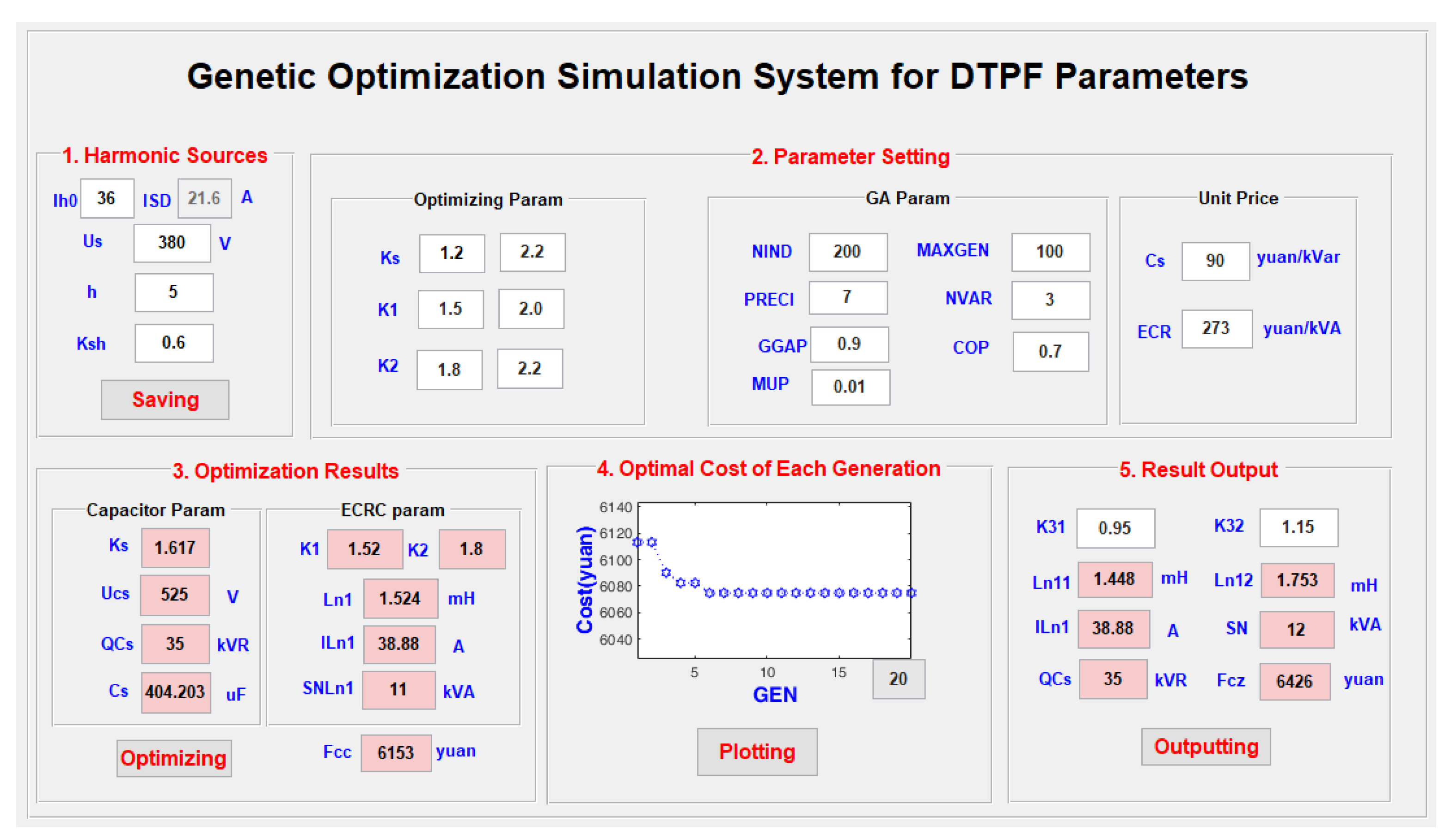
5.4. Optimization Simulation System

The genetic optimization simulation system for DTPF parameters is developed by-GUIDE tool in MATLAB 2019a. This optimization simulation system mainly consists of harmonic source, parameter settings (optimization parameters, GA parameters, and unit price), optimization results, optimal cost of each generation, and result output. Its main interface is shown in Figure 8.
In Figure 8, the designed “*.m” program is called by setting the CallBack function of the “button” to complete its design work. The specific steps are as follows:
Step 1: Input the parameters of harmonic source (including the h-th harmonic current I h 0 , voltage U s , harmonic order h, and harmonic absorption coefficient K s h ), and click the “Saving” button to call the corresponding callback program to save the harmonic source parameters.
Step 2: Complete parameter setting, including optimizing parameters, genetic algorithm (GA) parameters, and unit price.
Step 3: Click the “Optimizing” button to call the corresponding callback program so as to complete the electrical parameter optimization design of the DTPF.
Step 4: Click the “Plotting” button to call the corresponding callback program to display the optimal cost of each generation.
Step 5: Click the “Outputting” button to call the corresponding callback program to output the ECRC machining parameters.

6. Cases of Electrical Parameter Design

By setting the harmonic source parameters, the electrical parameters of the filter capacitor and ECRC under the lowest total cost can be designed and optimized.

6.1. Settings of Harmonic Source Parameters and Optimization Parameters

With the harmonic current to be suppressed in practical engineering applications as the object, the harmonic source parameters are set. The detailed parameter settings of harmonic source are shown in Table 3.
The parameter optimization setting is as follows:
  • Optimization parameters:
The relationship coefficient K s ranges from 1.2 to 2.2; the ECRC selection coefficient K 1 ranges from 1.5 to 2.0; the harmonic absorption coefficient K 2 ranges from 1.8 to 2.2.
  • GA parameters
The number of individuals (NIND) is 200; the maximum number of genetic generations (MAXGEN) is 100; the precision of variables (PRECI) is 7; the number of the variable (NVAR) is 3; the generation gap (GGAP) is 0.9; the crossover rate (COP) is 0.7; and the mutation probability (MUP) is 0.01.
  • Unit prices:
The unit price of the capacitor is 90 CNY/kVar, and the unit price of the ECRC is 273 CNY/kVA.

6.2. Parameter Optimization Results

According to the harmonic source parameters settings in Table 3 and the optimization parameters, the optimization results of DTPF electrical parameters are given in Table 4.

6.3. Output of Parameter Optimization Results

Based on the data presented in Table 4, the output of the parameter optimization results is obtained as shown in Table 5.

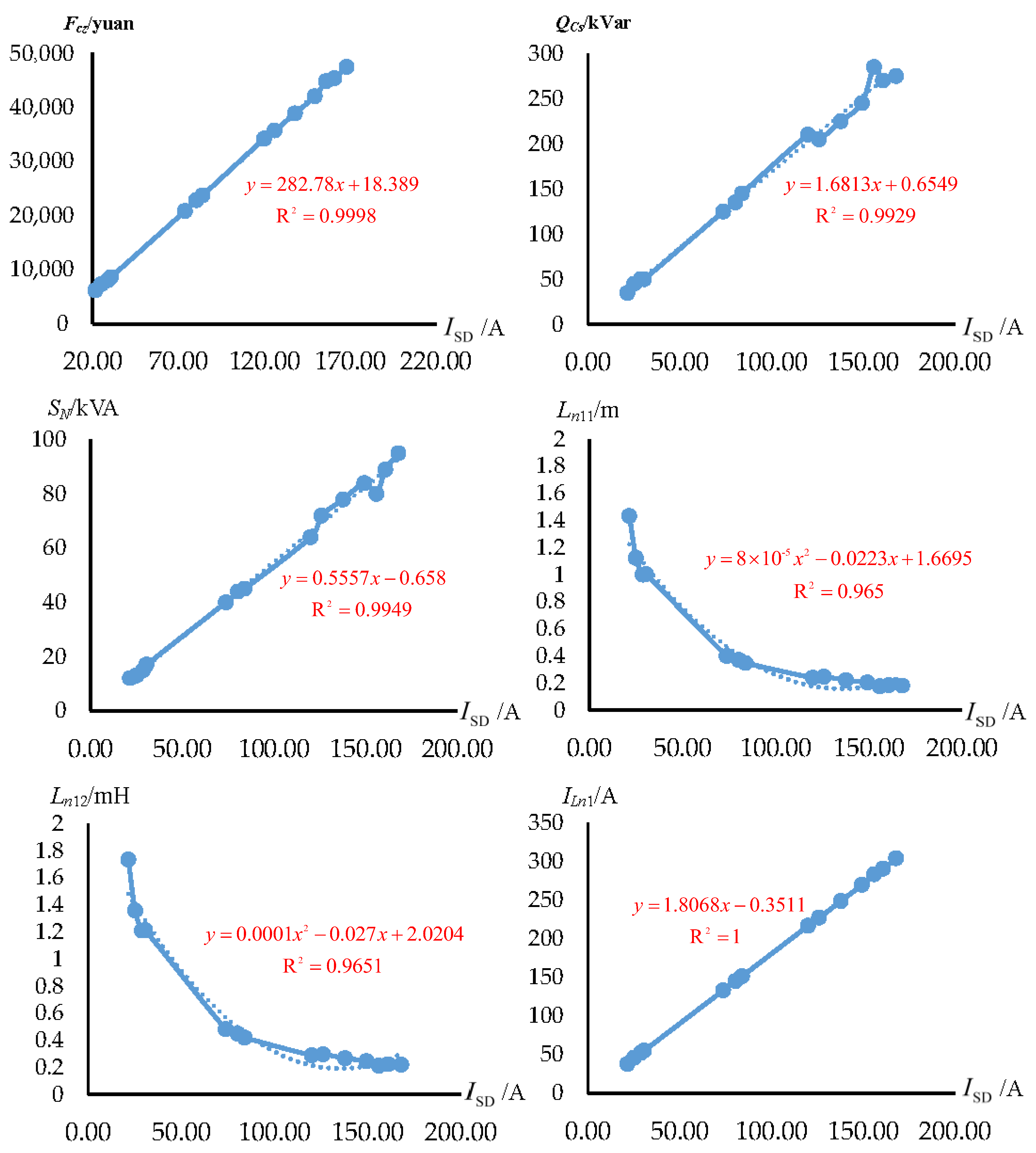
6.4. Rapid Estimation of Electrical Parameters

Based on the data in Table 3, Table 4 and Table 5, the relationship curves between the total cost, and electrical parameters and I S D are plotted by the data fitting method in Figure 9.
Figure 9 shows the relationship curves of the design value of the h-th harmonic current absorbed by DTPF ( I S D ) with the total cost ( F c z ), the filter capacitor’s capacitance ( Q C s ), and the machining rated apparent power ( S N ), the lower limit of inductance ( L n 11 ), the upper limit of inductance ( L n 12 ), and the rated current ( I L n 1 ) of ECRC.
According to Figure 9, the relationship model between the total cost ( F c z ), and electrical parameters ( Q C s , S N , L n 11 L n 12 , I L n 1 ) and the design value of harmonic current absorbed by the DTPF ( I S D ) can be constructed as shown below:
F c c Q C s S N L n 11 L n 12 I L n 1 = 0 282.78 18.389 0 1.6813 0.6549 0 0.5557 0.658 8 × 10 5 0.0223 1.6695 1 × 10 4 0.027 2.0204 0 1.8068 0.3511 × I S D 2 I S D 1
Furthermore, according to I S D , the total cost and electrical parameters can be estimated by Equation (20).

6.5. Verification and Application

The DTPF is installed at the front end of the harmonic source in the low voltage side of the workshop transformer in a textile mill. Figure 10 shows the U-phase current of the harmonic source and its harmonic spectrum. It is clearly proven that there is a significant distortion of the current, and that the total harmonic distortion (THD) is proportionally high as 21.7%. Figure 11 presents the U-phase current of the harmonic source and its harmonic spectrum with the DTPF, using the electrical parameters corresponding to Number 8 in Table 5. We can notice that the THD is reduced to 2.6%, all within the standard IEEE harmonics limits of 5%. It is observed that the source current with the DTPF is clearly sinusoidal and a symmetrical current waveform.

7. Conclusions

Aiming at exploring the influences of DTPF electrical parameters on absorbing harmonic current, the harmonic current absorption coefficient, tuning performance and cost, the optimization design of the DTPF electrical parameters is devised. In order to characterize the magnitude of the absorbing harmonic current harmonic current absorbed by DTPF, the value range of the harmonic current absorption coefficient is determined to be 0.6–0.8. Moreover, to characterize the quantitative relationship between the absorption value of the harmonic current and the filter capacitor’s capacity, the relationship coefficient of DTPF is defined as the ratio of the absorbing harmonic current harmonic current absorbed (filtered) by DTPF to the capacity of the filter capacitor. For examining the impact of the filter capacitor’s capacity on the filter performance, the optimal range of the relationship coefficient is determined to be 1.2–2.2. The design method of filter capacitor’s capacity is also proposed. According to the harmonic absorption coefficient as well as the magnitude of harmonic source current, the absorbing harmonic current harmonic current absorbed by DTPF is determined, and then after considering the relationship coefficient, the capacity of the filter capacitor is achieved. In addition, the method for designing the rated parameters of the electromagnetic coupled reactance converter (ECRC) is presented. Considering the resonance conditions and the adjustment range in practical engineering projects, the inductance is calculated. Given the requirements in engineering applications, the rated current and capacity are calculated by the value of the absorbed harmonic current. With the genetic algorithm toolbox, a genetic optimization method for the DTPF electrical parameters is put forward. On this basis, a simulation system for optimizing the DTPF parameters is developed. Through this system, the capacitor capacitance, the inductance of ECRC, the current and other parameters corresponding to the lowest cost can be obtained and verified by examples. Based on the analysis of parameter optimization results, a relationship model is constructed by the data fitting methods, through which the cost and electrical parameters of the DTPF can be quickly estimated. The use of our approach can optimize the electrical parameters of DTPF, improve the harmonic suppression effectiveness and lead to a more symmetrical waveform, thus avoiding problems to the power grid. The research results of this study not only provide a basis for the design of ECRC, but also lay a foundation for the machining DTPF. The future development direction of DTPF will be to seek the development of core components, and try to replace filter capacitors with supercapacitors with enhanced electrochemical performance [34,35].

Author Contributions

Y.W. contributed to the conception of the study, the background research, method design and analysis of the experimental results, and wrote the manuscript; K.Y. helped perform the analysis with constructive suggestions, verified this method and revised the manuscript; H.L. performed the research work and experimental analysis; Y.Y. provided an important suggestion about the framework of this paper and revised the manuscript. All authors have read and agreed to the published version of the manuscript.

Funding

The Fundamental Research Funds for the National Natural Science Foundation of China under Grant [61703318].

Institutional Review Board Statement

Not applicable.

Informed Consent Statement

Not applicable.

Data Availability Statement

Not applicable.

Acknowledgments

This work was supported by the Fundamental Research Funds for the National Natural Science Foundation of China under Grant 61703318.

Conflicts of Interest

The authors declare no conflict of interest.

References

  1. Li, D.; Yang, K.; Zhu, Z.Q.; Qin, Y. A Novel Series Power Quality Controller with Reduced Passive Power Filter. IEEE Trans. Ind. Electron. 2017, 64, 773–784. [Google Scholar] [CrossRef]
  2. Lee, T.L.; Wang, Y.C.; Li, J.C.; Guerrero, J.M. Hybrid active filter with variable conductance for harmonic resonance suppression in industrial power systems. IEEE Trans. Ind. Electron. 2015, 62, 746–756. [Google Scholar] [CrossRef] [Green Version]
  3. Mboving, A.; Stéphane, C. Investigation on the Work Efficiency of the LC Passive Harmonic Filter Chosen Topologies. Electronics 2021, 10, 896. [Google Scholar] [CrossRef]
  4. Dovgun, V.P.; Egorov, D.E.; Shevchenko, E.S. Parametric synthesis of passive filter-compensating devices. Russ. Electr. Eng. 2016, 87, 28–34. [Google Scholar] [CrossRef]
  5. Bollen, M.H.; Das, R.; Djokic, S.; Ciufo, P.; Meyer, J.; Rönnberg, S.K.; Zavodam, F. Power quality concerns in implementing smart distribution-grid applications. IEEE Trans. Smart Grid 2017, 8, 391–399. [Google Scholar] [CrossRef] [Green Version]
  6. Kalaskar, M.N.R.; Holmukhe, M.R. Report On Harmonics Generation and Mitigation in Power System. Int. J. Eng. Res. 2016, 5, 772–774. [Google Scholar]
  7. Kalair, A.; Abas, N.; Kalair, A.R.; Saleem, Z.; Khan, N. Review of harmonic analysis, modeling and mitigation techniques. Renew. Sustain. Energy Rev. 2017, 78, 1154–1187. [Google Scholar] [CrossRef]
  8. Zobaa, A.F. Mixed-Integer Distributed Mixed-Integer Distributed Ant Colony Multi-Objective Optimization of Single-Tuned Passive Harmonic Filter Parameters. IEEE Access 2019, 7, 44862–44870. [Google Scholar] [CrossRef]
  9. Othman, A.M.; Gabbar, H.A. Enhanced microgrid dynamic performance using a modulated power filter based on enhanced bacterial foraging optimization. Energies 2017, 10, 776. [Google Scholar] [CrossRef] [Green Version]
  10. Song, Q.; Chen, S.; Zhao, Z.; Liu, Y.; Alsaadi, F.E. Passive filter design for fractional-order quaternion-valued neural networks with neutral delays and external disturbance. Neural Netw. 2021, 137, 18–30. [Google Scholar] [CrossRef] [PubMed]
  11. Alam, K.S.; Xiao, D.; Zhang, D.; Rahman, M.F. Single-Phase Multicell AC–DC Converter with Optimized Controller and Passive Filter Parameters. IEEE Trans. Ind. Electron. 2018, 66, 297–306. [Google Scholar] [CrossRef]
  12. Zagirnyak, M.; Maliakova, M.; Kalinov, A. An analytical method for calculation of passive filter parameters with the assuring of the set factor of the voltage supply total harmonic distortion. Prz. Elektrotechniczn 2017, 1, 197–200. [Google Scholar] [CrossRef] [Green Version]
  13. Leite, J.C.; Abril, I.P.; de Lima Tostes, M.E.; De Oliveira, R.C.L. Multi-objective optimization of passive filters in industrial power systems. Electr. Eng. 2017, 99, 387–395. [Google Scholar] [CrossRef]
  14. Bajaj, M.; Sharma, N.K.; Pushkarna, M.; Malik, H.; Alotaibi, M.A.; Almutairi, A. Optimal Design of Passive Power Filter using Multi-objective Pareto-based Firefly Algorithm and Analysis under Background and Load-side’s Nonlinearity. IEEE Access 2021, 9, 22724–22744. [Google Scholar] [CrossRef]
  15. Busarello, T.D.C.; Pomilio, J.A.; Simões, M.G. Passive filter aided by shunt compensators based on the conservative power theory. IEEE Trans. Ind. Appl. 2016, 52, 3340–3347. [Google Scholar] [CrossRef]
  16. Jannesar, M.R.; Sedighi, A.; Anvari-Moghaddam, M.S.A.; Guerrero, J.M. Optimal probabilistic planning of passive harmonic filters in distribution networks with high penetration of photovoltaic generation. Int. J. Electr. Power 2019, 110, 332–348. [Google Scholar] [CrossRef]
  17. Mohammadi, M.; Rozbahani, A.M.; Montazeri, M. Multi criteria simultaneous planning of passive filters and distributed generation simultaneously in distribution system considering nonlinear loads with adaptive bacterial foraging optimization approach. Int. J. Electr. Power 2016, 79, 253–262. [Google Scholar] [CrossRef]
  18. Beres, R.N.; Wang, X.; Liserre, M.; Blaabjerg, F.; Bak, C.L. A Review of Passive Power Filters for Three-Phase Grid-Connected Voltage-Source Converters. IEEE J. Emerg. Sel. Top. Power Electron. 2016, 4, 54–69. [Google Scholar] [CrossRef] [Green Version]
  19. Solatialkaran, D.; Khajeh, K.G.; Zare, F. A Novel Filter Design Method for Grid-Tied Inverters. IEEE Trans. Power Electr. 2021, 36, 5473–5485. [Google Scholar] [CrossRef]
  20. Leite, J.C.; Abril, I.P.; Azevedo, M.S.S. Capacitor and passive filter placement in distribution systems by nondominated sorting genetic algorithm-II. Electr. Power Syst. Res. 2017, 143, 482–489. [Google Scholar] [CrossRef]
  21. Swain, S.D.; Ray, P.K.; Mohanty, K.B. Improvement of power quality using a robust hybrid series active power filter. IEEE Trans. Power Electr. 2016, 32, 3490–3498. [Google Scholar] [CrossRef]
  22. Omar, R.; Tan, Z.H.; Rasheed, M.; Sulaiman, M. An Improvement of Shunt Active Power Filter using Effective Controller for Different Load Condition. J. Eng. Appl. Sci. 2020, 15, 1311–1321. [Google Scholar] [CrossRef] [Green Version]
  23. Litrán, S.P.; Salmeron, P. Analysis and design of different control strategies of hybrid active power filter based on the state model. IET Power Electron. 2012, 5, 1341–1350. [Google Scholar] [CrossRef]
  24. Schäffer, G.J.; Moura, F.A.M.; Mendonça, M.V.B. Conservative Power Theory (CPT): A New Approach to the Tuned Passive Filter Design. Renew. Energy Power Qual. J. 2019, 17, 245–250. [Google Scholar] [CrossRef]
  25. Aiello, M.; Cataliotti, A.; Favuzza, S.; Graditi, G. Theoretical and experimental comparison of total harmonic distortion factors for the evaluation of harmonic and interharmonic pollution of grid-connected photovoltaic systems. IEEE Trans. Power Deliv. 2006, 21, 1390–1397. [Google Scholar] [CrossRef]
  26. Wang, Y.; Yuan, Y.; Chen, J. A novel electromagnetic coupling reactor based passive power filter with dynamic tunable function. Energies 2018, 11, 1647. [Google Scholar] [CrossRef] [Green Version]
  27. Wang, Y.; Yuan, Y.; Chen, J. Study of harmonic suppression of ship electric propulsion systems. J. Power Electron. 2019, 19, 1303–1314. [Google Scholar]
  28. Wang, Y.F.; Yuan, Y.X. Development of a Soft Starter with Current-Limiting, Reactive Power Compensation and Harmonic Filtering. Appl. Mech. Mater. 2014, 462–463, 658–661. [Google Scholar] [CrossRef]
  29. Wang, Y.F.; Yuan, Y.X.; Chen, J.; Cheng, Q.J. A Dynamic Reactive Power Compensation Method of Super High-Power and High-Voltage Motor. Appl. Mech. Mater. 2014, 602–605, 2828–2831. [Google Scholar] [CrossRef]
  30. Wang, Y.F.; Yuan, Y.X. A dynamic reactive power compensation method for high-power and high-voltage electronic motors based on self-adaptive fuzzy PID control. In Proceedings of the Guidance, Navigation and Control Conference IEEE, Nanjing, China, 12–14 August 2016; pp. 10–15. [Google Scholar]
  31. Chen, J.; Xiao, L.; Yuan, Y.X.; Yang, K.; Lei, L.; Mao, B.P.; Chen, Z. Development of passive dynamic power filter based on MCU. J. Wuhan Univ. Technol. 2013, 35, 144–146. [Google Scholar]
  32. Mercorelli, P. Parameters identification in a permanent magnet three-phase synchronous motor of a city-bus for an intelligent drive assistant. Int. J. Model. Identif. Control 2014, 21, 352–361. [Google Scholar] [CrossRef]
  33. Su, Y.; Zheng, C.; Mercorelli, P. Global Finite-Time Stabilization of Planar Linear Systems with Actuator Saturation. Trans. Circ. Syst. II Express Briefs 2017, 64, 947–951. [Google Scholar] [CrossRef]
  34. Othman, A.M.; Gabbar, H.A. A novel electrode for supercapacitors: Efficient PVP-assisted synthesis of Ni3S2 nanostructures grown on Ni foam for energy storage. Dalton Trans. 2020, 49, 4050–4059. [Google Scholar]
  35. Yedluri, A.; Anitha, T.; Kim, H.J. Fabrication of Hierarchical NiMoO4 /NiMoO4 Nanoflowers on Highly Conductive Flexible Nickel Foam Substrate as a Capacitive Electrode Material for Supercapacitors with Enhanced Electrochemical Performance. Energies 2019, 12, 1143. [Google Scholar] [CrossRef] [Green Version]
Figure 1. Dynamic tuning passive filter. (a) Photograph. (b) Block diagram. (c) Simplified topology.
Symmetry 13 01115 g001
Figure 2. Equivalent harmonic circuit of the filter system.
Symmetry 13 01115 g002
Figure 3. Steady-state harmonic model of the filter system.
Symmetry 13 01115 g003
Figure 4. Schematic diagram of the DTPF test platform.
Symmetry 13 01115 g004
Figure 5. The broken lines of I h and I f under the four conditions in Test (I).
Symmetry 13 01115 g005
Figure 6. The broken lines of I h and I f under the four conditions in Test (II).
Symmetry 13 01115 g006
Figure 7. Optimization design flow chart of DTPF electrical parameters.
Symmetry 13 01115 g007
Figure 8. Main interface of genetic optimization simulation system of DTPF parameters.
Symmetry 13 01115 g008
Figure 9. Relationship curves between electrical parameters and absorbed current.
Symmetry 13 01115 g009
Figure 10. U-phase current of the harmonic source and its harmonic spectrum without DTPF.
Symmetry 13 01115 g010
Figure 11. U-phase current of the harmonic source and its harmonic spectrum with DTPF.
Symmetry 13 01115 g011
Table 1. Results of Test (I).
Number I h 0 (A) I f (A) I j (A)
17.075.21.81
210.65.849
312.736.056.4
417.686.4910.05
Table 2. Results of Test (II).
Number Q Cs (kVar) I h 0 (A) I f (A) I j (A) K s
11017.686.4910.051.54
21517.689.538.271.57
32017.6813.42.41.49
42517.6815.722.081.59
Table 3. Parameter settings of harmonic source.
Number I s 0 (A) U s (A)h K sh I SD (A)
136.00380.0050.621.60
236.00380.0050.7025.20
336.00380.0050.8028.80
436.00380.0050.8530.60
5123.00380.0050.6073.80
6134.00380.0050.6080.40
7140.00380.0050.6084.00
8200.00380.0050.60120.00
9210.00380.0050.60126.00
10229.80380.0050.60137.88
11229.80380.0050.65149.37
12260.00380.0050.60156.00
13229.80380.0050.70160.86
14280.00380.0050.60168.00
Table 4. Optimization results of DTPF electrical parameters.
Number K s U Cs Q Cs C s k 1 k 2 L n 1 I Ln 1 S NLn 1 F cc
11.38952535404.2031.5041.8061.50838.016116153
21.62552545519.691.5161.8191.18245.836127326
31.64152550577.4331.51.8061.05352.021138049
41.52352550577.4331.5041.81.05655.08158595
51.6495251251443.5821.51.8030.421133.0723520,805
61.6415251351559.0691.5041.80.391144.723922,797
71.7125251451674.5551.5121.80.366151.23923,697
81.7435252102425.2181.5081.8030.252216.3785634,188
91.6095252052367.4751.5121.80.259226.86335,649
101.6175252252598.4481.51.80.234248.1846838,814
111.6255252452829.4211.5041.8030.215269.3367341,979
121.8065252853291.3681.51.8130.185282.7657044,760
131.6725252703118.1381.5041.8030.195290.0557745,321
141.6335252753175.8811.51.8060.191303.4588347,409
Table 5. Output of Parameter Optimization Results.
Number Q Cs L n 11 L n 12 I Ln 1 S N F cz
1351.4331.73439.016126426
2451.1231.35945.836137599
35011.21152.021158595
4501.0031.21455.08179141
51250.40.484133.0724022,170
61350.3710.45144.724424,162
71450.3480.421151.24525,335
82100.2390.29216.3786436,372
92050.2460.298226.87238,106
102250.2220.269248.1847841,544
112450.2040.247269.3368444,982
122850.1760.213282.7658047,490
132700.1850.224290.0558948,597
142750.1810.22303.4589550,685
Publisher’s Note: MDPI stays neutral with regard to jurisdictional claims in published maps and institutional affiliations.

