Abstract
Diesel particulate filters (DPF) are typically used for particle filtration in vehicle exhausts after a treatment system. The monolith inside a DPF is a symmetrical column structure, frequently an axisymmetric cylinder structure where filtration and regeneration occur. Due to the complex structure before the symmetric monolith, the internal particle distribution is not uniform, which leads to an uneven temperature change when regeneration occurs. During thermal regeneration, the temperature field inside a DPF is affected by the particle load, exhaust temperature and exhaust flow. The relationship between the temperature gradient and velocity vector is also a key factor influencing regeneration performance. Based on the particle-loading test method, a bench for thermal distribution testing during regeneration was built. Via experiments and simulations, the temperature field in an axisymmetric monolith during particle combustion given an uneven particle distribution was analyzed. Through field synergy analysis of the temperature and velocity fields in the monolith, the influence of connection cones with different structures on heat transfer enhancement was studied. The results indicated that compared with a monolith with a conventional linear cone, the radial temperature gradient is 1.1 °C/mm lower, the area of enhanced regeneration is larger, and the regeneration rate is improved in the monolith with a streamlined cone.
1. Introduction
With increasingly stringent emission regulations, strict requirements have been proposed to control particulate matter emissions. Particulate matter is one of the main pollutants in vehicle exhaust emissions. At present, the most effective aftertreatment device to reduce particulate matter emissions is the wall-flow diesel particulate filter (DPF). The monolith substrate is either ceramic or metallic and comprises numerous parallel narrow channels (on the order of 1 mm) that increase the area of the surface on which either filtration or regeneration occur. The regeneration is the process of removing particles by combustion, when the particles accumulated to the loaded requirement.
DPF research has focused on the characteristics of the particle distribution, deposition, regeneration and especially thermal distribution [1,2]. The distribution and deposition characteristics of particles are influenced by many factors, such as the inlet air flow, pore structure, wall roughness and material properties. The change in particle deposition and distribution directly affects the change in pressure drop [3]. The study of the regeneration process has also considered the distribution and deposition of particles. An uneven particle distribution leads to local heat concentration during the regeneration process, which is a great challenge to the temperature resistance of the filter material, leading to thermal stress and a pressure drop [2,4].
During thermal regeneration, the temperature of the DPF front surface should be raised to above 500 °C, and a relatively high exhaust temperature should be maintained for a long period of time to ensure a high regeneration efficiency [5]. Due to the complex and changeable working conditions during actual road driving, the internal temperature and regeneration process in DPFs are affected by the exhaust temperature and flow rate, resulting in uncontrolled characteristics under specific working conditions [6]. When uncontrolled regeneration occurs, DPFs are subjected to a high thermal load and thermal stress. Once the peak temperature and temperature gradient exceed the corresponding critical allowable ranges, monolith melting or cracking readily occurs.
Previous research has examined the temperature field, change in the deposition layer and pressure drop during regeneration. The numerical simulation method has been the main research technique [7,8,9]. Yamamoto et al. applied the lattice Boltzmann method (LBM) and performed combustion simulations of the three-dimensional porous structure inside a monolith and the distribution of particulate matter deposited at different depths along the monolith wall at varying exhaust temperatures. They found that at a DPF temperature of 600 K, the deposition of particulate matter was not affected by oxidation. When the DPF temperature exceeded 800 K, DPF clogging could be avoided, and continuous regeneration could be achieved [10]. Meng et al. analyzed the DPF regeneration performance (the temperature, temperature gradient in the monolith, pressure drop and regeneration efficiency) at different flow rates and particle loadings [11].
To explore the influence of the particle deposition layer thickness on the temperature during regeneration, Chen et al. measured the variation in temperature by varying the layer thickness in the inlet channel during regeneration and found that at a constant inlet temperature of 620 °C, the maximum temperature occurred at the gas–particle interface. Moreover, at a deposition rate of 10 g/L or lower, the temperature difference across the filter layer was usually less than 10 °C [12].
The pressure drop in the whole system during regeneration is also of concern to researchers. Psarianos et al. employed a miniature DPF, actual DPF products and a simulation method to compare and analyze the pressure drop changes in the process of filtration and regeneration and calibrated a simulation calculation model against experimental data [13].
In addition, the influence of the connection cone on particle deposition has been studied to a certain extent. By comparing the influence of different expansion angles of the connection cone on the particle deposition process in the monolith, it was determined that diameter changes in the exhaust pipe to the connection cone yielded an uneven distribution of particle deposition [14]. Maximum deposition was observed at the center of the monolith, which could lead to a nonuniform temperature field. Moreover, the longer the connection cone at the inlet (the smaller the expansion angle), the smaller the deposited layer thickness and difference between the central and peripheral temperatures during regeneration were and the more uniform the temperature field was, which also corresponded to the observed variations in flow uniformity.
In summary, the thermal distribution in the DPF system is a very important evaluation index that directly determines the reliability and service life, and the thermal distribution during regeneration is affected by many aspects. The connection cone has been researched in terms of flow organization and particle distribution in the monolith, but the influence of the cone on the temperature field during the regeneration process remains unclear.
This article investigated on the cone’s influence on the thermal distribution. During regeneration tests, the peak temperature and internal temperature gradient were determined. A comparative study of the thermal distribution in the monolith with a streamlined cone deploying nonuniform rational B-splines (NURBS) and a conventional linear cone was carried out. Synergy simulations of the velocity vector and temperature field were conducted to study the regeneration performance.
2. Materials and Methods
2.1. Setup and Experimental Method to Determine the Thermal Distribution
2.1.1. The Setup for the Thermal Distribution
To study the thermal distribution in the monolith, a test bench comprising a heating furnace and front preheating pipe was designed and built, and the model of the heating furnace was DAHEI BMLT-1800. As shown in Figure 1, the DAHEI BMLT-1800 heating furnace contains three heating zones. The length of each zone is 250 mm with a diameter of 150 mm, and the highest set temperature is 1800 °C. The highest heating temperature of the preheating pipe is 500 °C. A schematic diagram of the bench is shown in Figure 2. The air flow rate into the front preheating pipe was controlled with a front pressure regulator, and the air entering the electric heating furnace was preheated to 400 °C, with a heating zone temperature of 500 °C. After passing through the monolith, which was loaded with particles, exhaust gas was discharged into the laboratory exhaust gas treatment pipeline through an exhaust pipe. Monoliths under particle loading were evaluated in repeated particle-loading tests [15]; the test setup is shown in Figure 3. After the monolith is loaded with particles, the monolith will be removed from the setup shown in Figure 3 and put into the electric heating furnace for the combustion test as described in the above.
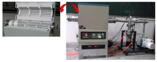
Figure 1.
Electric heating furnace, DAHEI BMLT-1800. The heating zone temperature was 500 °C.
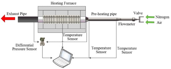
Figure 2.
Schematic of the particle combustion bench, including heating furnace and preheating pipe.
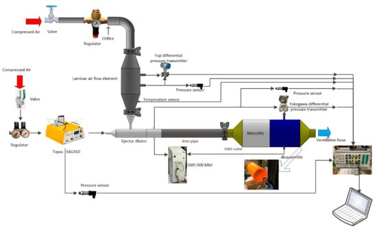
Figure 3.
Schematic of the particle loading setup. To get the monolith loaded with particles, the particle aerosol should be mixed with the air from the laminar flow element in the ejector dilutor [15].
To avoid preoxidation of the particulate matter in the monolith, nitrogen was first transmitted when heating the electric heating furnace and preheating pipe. After the set temperature was reached, the nitrogen gas valve was closed, and the air inlet valve was opened. After heating to 400 °C, air entered the heating furnace, and particle combustion occurred in the monolith.
The temperature inside the monolith was relatively high during the regeneration process. Therefore, a K-type thermocouple was selected for temperature data collection. The thermocouple diameter was selected according to the channel size of the monolith. A thermocouple with a diameter of 1 mm and a length of 300 mm was adopted, with a temperature measurement range of up to 1200 °C.
In addition, a supporting tube was designed to protect the monolith and the thermocouple. The supporting tube consisted of heat-resistant tubes with an inner diameter of 108 mm. The wall surface of the tubes also provided a conductor entrance and sensor port. The monolith was installed ahead of the test device. A temperature acquisition device was installed at the back end of the monolith, and the thermocouple was installed along the circumference direction, inserted into the rear channel of the monolith and placed at the measuring position. The thermocouple connector was affixed to the bracket and connected to the designed signal collector. The temperature of each test point was monitored and recorded by the computer. The assembled temperature distribution test device is shown in Figure 4.
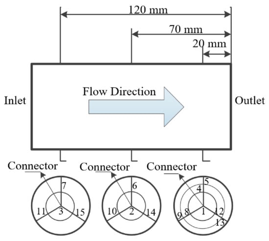
Figure 4.
Distribution of the sampling points in the monolith.
According to the length and diameter of the monolith, a total of 15 temperature collection points were set. Three sections were designed along the axial direction of the monolith, and four or seven collection points were placed in each section. The properties of the monolith are listed in Table 1 [15].

Table 1.
Physical properties of the full-sized monolith.
Seven collection points were designed across the back face of the monolith, points 1 (central axis position point), 4, 5, 8, 9, 12 and 13, and were uniformly distributed along the circumferential direction over 120°. The distance between points 4, 8, 12 and 1 was 20 mm, and the distance between points 5, 9, 13 and 1 was 40 mm. Four collection points were arranged in the middle section, namely, points 2 (central axis position point), 6, 10 and 14, which were uniformly distributed along the circumferential direction over 120°. The distance between points 6, 10, 14 and 2 was 20 mm. Four collection points were arranged across the front entrance end face, namely, points 3 (central axis position point), 7, 11 and 15, and they were uniformly distributed along the circumferential direction over 120°. The distance between points 7, 11, 15 and 3 was 20 mm. The specific collection point layout is shown in Figure 4.
The axial temperature gradient in the monolith from the front end to the back end was measured through the three points (points 1, 2, and 3) set along the direction of the central axis. Based on the configuration, the particle matter distribution along the channel and the deposition conditions at the front and back ends was verified. The test points along the circumference in the same section at different radical distances were used to measure the radial temperature gradient. Figure 5 shows the installation of the thermocouple inside the monolith; the white material is asbestos used to fix the monolith.
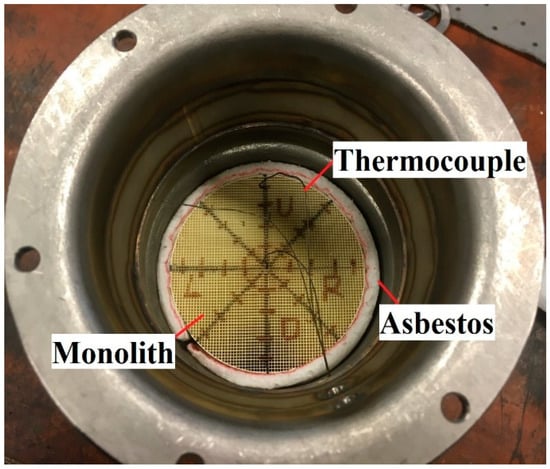
Figure 5.
Thermocouple placement.
2.1.2. Experimental Method for the Thermal Distribution
The thermal distribution test of the monolith was conducted as a follow-up experiment to the particle-loading test. The particle-loading test is a repeated test based on previous research [15].
The loaded monolith was placed in the supporting tube and installed in the heating furnace. First, during monolith pretreatment, the nitrogen valve was opened to fill the whole system with nitrogen. The outlet temperature of the preheating pipe was 400 ± 5 °C, and the duration of pretreatment was approximately one hour. The specific heating time was measured by the outlet temperature sensor. In addition, the three heating areas of the heating furnace were opened, and the heating temperature was controlled at 500 ± 5 °C with a heating rate of 10 °C/min. The process duration was also set to approximately one hour. After the predetermined temperature was reached throughout the whole system, the nitrogen valve was closed, and the air valve was opened. Moreover, the flowmeter was adjusted to the predetermined flow rate and the oxidation combustion process (regeneration process) of particulate matter was initiated. The regeneration time was 5 min. During the regeneration process, the temperature change at each test point was monitored.
Under the conditions above, loaded monoliths containing either a conventional Cone 1 or NURBS Cone 2 were adopted as comparative test samples. Both sample monoliths were loaded at 5.1 g/1.19 L (monolith volume) = 4.29 g/L, and the air flow rate through the flowmeter was 13 L/s.
2.2. Influence of Multiple Fields on Heat Transfer in the Monolith
The energy equation of the heat transfer process indicates that the heat transfer process is affected by the physical parameters of the fluid, in addition to the comprehensive influence of the temperature and velocity vectors, which suggests that heat transfer in the fluid is affected by the synergistic effect between the velocity and temperature fields [16,17]. At present, the application of field synergy research to the heat transfer mechanism in DPFs remains at the initial stage [18].
2.2.1. Field Synergy Theory
Adopting the boundary layer of two-dimensional (x and y) flow as the research object [19], is the thickness of the thermal boundary layer of the plate, is the incoming flow temperature, is the incoming flow velocity, is the flat-plate temperature.
The energy conservation equation of the convective heat transfer is as follows:
where is the density, kg/m3, is the thermal conductivity of the fluid, W/(m·K), is the specific heat capacity, J/(kg·K).
The energy conservation equation of heat conduction in the thermal boundary layer is as follows:
where is the intensity of internal heat source, W/m3.
Equations (1) and (2) reveal that the convective term can be regarded as the heat source term, so the convective heat transfer in the flat plate can be regarded as a heat transfer problem with an internal heat source. The following equations can be obtained by integrating both sides of Equation (1):
where is the convective heat transfer between the fluid and flat plate, kW/m2.
Equation (3) can be rewritten in vector form as follows:
The following dimensionless variables are introduced:
By substituting Equation (6) into Equation (5) and after term rearrangement, Equation (7) is obtained:
where is the Reynolds number, is Prandtl Number, and is the Nussle number, with , where is the convective heat transfer coefficient given thermal boundary layer thickness , is the characteristic length given thermal boundary layer thickness , and is the thermal conductivity given thermal boundary layer thickness .
The integrand can be written as follows:
where is the angle between the velocity and temperature gradient vectors (the heat flow vector) during flow.
Equations (7) and (8) suggest that there are three main ways to enhance heat transfer [20]: 1. increase the Prandtl number and adjust the fluid physical properties, such as increasing the viscosity or specific heat capacity of the fluid; 2. increase the Reynolds number, such as enhancing the flow rate and reducing the channel radius; 3. increase the value of the dimensionless integral , which is related to flow and physical properties, etc.
Based on Equation (1), when the physical parameters of , and remain constant, the heat flow along the boundary can be obtained from the temperature and velocity fields, and the surface heat transfer coefficient can thus be determined. Therefore, three vector fields occur in the convective heat transfer area: 1. the absolute value of the temperature gradient ; 2. the absolute value of the velocity ; 3. the angle cosine field .
The above can also be regarded as two vector fields: 1. temperature gradient field ; 2. velocity field .
Equation (3) indicates that in the case of the determination of the physical properties and flow rate, the heat flow along the boundary depends on the equivalent intensity of the heat source, which suggests that when Pr and Re remain constant, Nu is determined by the dimensionless equivalent heat source. The flow equivalent heat source depends not only on the velocity and temperature fields but also on the included angle between the velocity field and temperature gradient. If heat exchange is enhanced by adjusting the equivalent heat source intensity, the synergistic effect between the velocity and heat flow fields is improved. The degree of synergy between the velocity and temperature fields is embodied by the following factors [21,22]:
- ➀
- The distributions of the velocity and temperature should be as uniform as possible under certain conditions involving the maximum velocity and temperature difference.
- ➁
- The absolute value of the cosine of the angle between the velocity and temperature gradient vectors should be maximized, which indicates that the angle should be as large as possible ( > 90°) or as small as possible ( < 90°).
2.2.2. Multifield Synergy Model
The multifield synergy process of particle combustion in the monolith was studied. The model and mesh division conditions of the particle filter were the same as those described in previous research [23,24]. Choosing the parameters of the wall-flow monolith as a reference, the initial conditions of the monolith based on two connection cones were designed according to the obtained test data, and the cone properties are summarized in Table 2.

Table 2.
Physical properties of the cones [15].
Carbon black particles were deployed in the experiment. According to the oxidation combustion process of particles in the monolith, a chemical reaction model of carbon black particles was established to characterize the particle combustion process to simplify the calculations [25,26,27].
- (1)
- Chemical reaction model of C-O2
In this reaction model, when the exhaust temperature reaches the ignition temperature of soot particles, carbon smoke particles are oxidized and burned, thereby discharging any generated gas and achieving the purpose of removal.
The corresponding chemical reaction rate is given by the following:
where is a proportional parameter of the generation of CO through oxidation, is the pre-factor corresponding to the chemical reaction, is the activation energy required for the chemical reaction, R is the universal gas constant, is the temperature of the monolith, and is the O2 concentration.
- (2)
- C-O2-NO2
In this chemical reaction model, NO2 is oxidized with the soot particles to achieve purification. The regeneration system fundamentally applies this chemical reaction.
The chemical reaction rate between the particles and NO2 is given by the following:
where i denotes the different chemical reactions, and Equation (18) expresses the chemical reaction rate of Equations (16) and (17).
2.3. Numerical Analysis of Multifield Synergy
The fundamental field synergy demonstrates that the physical strengthening mechanism of convective heat transfer is based on the conductivity coefficient of the internal heat source. The intensity of the heat source is determined not only by the flow rate, temperature differential and fluid properties but also by the included angle between the velocity vector and temperature gradient, which is the main criterion to evaluate synergy optimization [28,29].
In this paper, a mathematical model of the field synergy was applied, and Fluent 18.0 was employed to simulate the multifield synergy during the particle oxidation combustion process in the monolith with a conventional cone and the monolith with a NURBS cone.
The structural model was based on the temperature distribution testing device of the axisymmetric monolith described in Section 2.1. The flow exhibits axisymmetric similarity; the two-dimensional calculation area obtained according to the model structure is shown in Figure 6. The size of the connecting cone, which exhibited an inlet diameter of 27.3 mm, was the same as that of Cone 1.
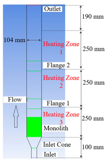
Figure 6.
Computational domain.
Gambit2.4.6 was applied to divide the two-dimensional model into grids, which were all structural grids. The number of grids was approximately 65,000. The calculation conditions were based on the setup data presented in Section 2.1. In addition to setting the initial velocity (approximately 22 m/s) in the simulation process, other inlet velocities (approximately 10 and 30 m/s) were considered and compared. The temperature of the inlet was set to 400 °C, the temperature of the heating zone was set to 500 °C, and the particle-loading mass flow was 0.004 g/s. A combustion model with a finite rate was chosen to describe the chemical model in the process of particle combustion. The settings of the other initial conditions and controlling parameters were basically the same as those provided in Section 2.1.
3. Results
Our results are reported in three parts. In Section 3.1 and Section 3.2, the experimental results for the thermal distribution of the monoliths with the two specific kinds of cone are presented, while Section 3.3 reports the results of the numerical simulation of multifield synergy and the subsequent study.
3.1. Thermal Distribution in the Monolith with the Conventional Cone
Table 3 lists the partial test results of the temperature field inside the monolith. The data were collected at 2 s intervals from the 190 s to the 210 s during the regeneration process. The temperature change obtained by each thermocouple for the loaded monolith using conventional Cone 1 is shown in Figure 7. The regeneration time was 5 min.

Table 3.
The temperature data of the loaded monolith with conventional Cone 1, °C.
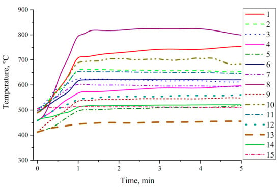
Figure 7.
Temperature of the loaded monolith with conventional Cone 1.
The highest temperature occurred at thermocouple No. 8, and the highest temperature reached approximately 833 °C. In other words, the maximum temperature was observed 20 mm from the outlet inside the monolith and 20 mm from the midpoint, and the highest temperature did not occur in thermocouple No. 1 at the central position, which indicates that the real temperature field inside the monolith cannot be determined based on an analysis of the flow characteristics or the physical appearance of the monolith during regeneration. The maximum temperature gradient also occurred between thermocouples No. 1 and No. 8, and the radial temperature gradient reached approximately 4.9 °C/mm. The axial temperature gradient between thermocouples No. 1 and No. 3 reached 0.14 °C/mm.
3.2. Thermal Distribution in the Monolith with the NURBS Cone
Under the same test conditions, the monolith with NURBS Cone 2 was also tested. The collected temperature results are shown in Figure 8. Compared to Figure 7, the temperature change recorded by the thermocouple near the inlet of the monolith was approximately the same, whereas the temperature at the end of the monolith exhibited a larger difference. The maximum temperature in the monolith with the NURBS cone was measured by thermocouple No. 1, and the maximum temperature reached 802 °C, which was lower than that in the monolith with Cone 1. However, based on the temperature data recorded by thermocouples No. 12 and No. 13, it is found that the highest temperatures were 620 and 497 °C, respectively, which are higher than those at the corresponding positions in the loaded monolith with Cone 1 (560 and 455 °C, respectively). In regard to thermocouples No. 5 and No. 9, the temperatures at the corresponding positions in the monolith with Cone 2 were also approximately 40 and 20 °C higher, respectively.
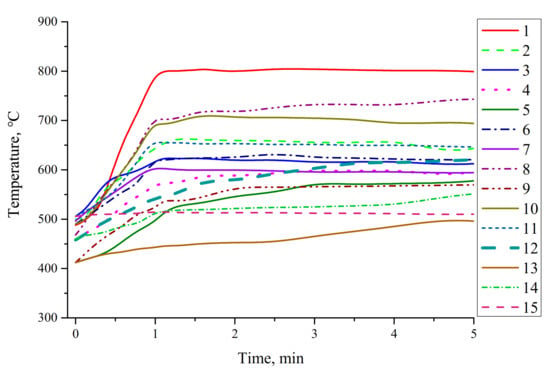
Figure 8.
Temperature of the loaded monolith with NURBS Cone 2.
This indicates that the temperature near the boundary is higher, the temperature difference between the boundary and middle position in the monolith is reduced, and the radical temperature gradient in the monolith between thermocouples No. 1 and No. 8 is reduced to approximately 3.8 °C/mm. However, the axial temperature gradient between thermocouples No. 1 and No. 3 increases to 1.31 °C/mm due to the temperature increase at thermocouple No. 1.
The following conclusions can be drawn from the above experiment on the temperature distribution in the monolith during the regeneration process:
- (1)
- The peak temperature in the loaded monolith with the conventional cone is higher than that in the loaded monolith with the NURBS cone, and the temperature gradient along the radial direction is higher.
- (2)
- Compared to the conventional cone, the thermal distribution in the monolith with the NURBS cone is more uniform. This indicates that when particulate matter is nonuniformly distributed inside the monolith, the zone existing more particulate, will generate a high temperature zone during combustion, resulting in a high temperature gradient along the radial and axial directions in the monolith.
- (3)
- The thermal distribution in the monolith is also influenced by many factors, including the monolith design, inlet temperature, exhaust flow, and characteristics of the monolith, which should be further studied and analyzed through simulations.
3.3. Results of the Numerical Simulation of Multifield Synergy
The recorded temperature data of the front surface of the monolith were selected for verification. Since the temperature change in the front surface was not greatly affected by the particle combustion process inside the monolith during the test, the collected data were relatively stable. The temperature data recorded by certain thermocouples (Nos. 3, 7, 11 and 15, which remained relatively stable during the 3rd min of the test) of conventional Cone 1 were selected for comparison. The results are shown in Figure 9. The difference in thermocouple No. 11, which exhibited the largest discrepancy between the simulation and recorded data, was approximately 8.33%. Considering the large measuring range of the thermocouple, the above error is reasonable.
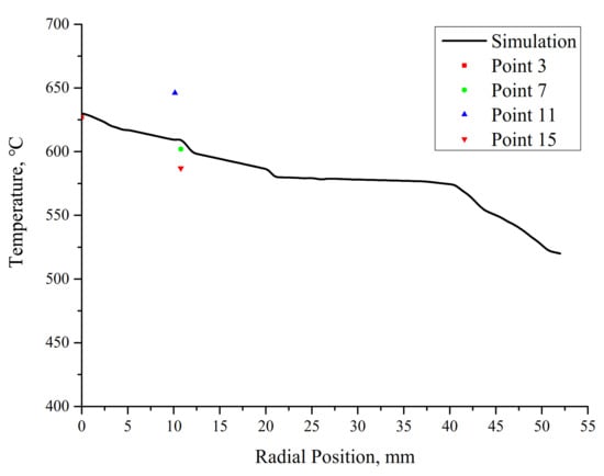
Figure 9.
Validation of the simulation results.
3.3.1. Study of the Synergy Area in the Monolith
According to the principle of field synergy, at < 90°, reducing between the velocity vector and temperature gradient could strengthen heat transfer. At > 90°, increasing between the velocity vector and temperature gradient could weaken heat transfer. For the convenience of calculation and research, the region where cosine > 0.8 ( < 36.9°) is considered the better-regeneration area with a good synergy in the regenerative combustion performance. The ratio of the better-regeneration area to the entire monolith regeneration area was statistically analyzed.
Under the same boundary conditions and only inlet velocity adjustment (10, 22, and 30 m/s), a cosine distribution diagram of the included angle between the velocity vector and temperature gradient in the monolith was obtained, as shown in Figure 10. As the calculation area was relatively large, only the part encompassing the monolith was selected for display purposes.
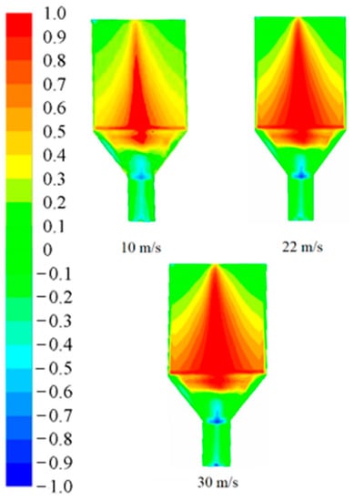
Figure 10.
Cosine distribution of the angle between the velocity vector and temperature gradient.
Figure 10 shows that the area exhibiting enhanced synergy (>0.8) in the monolith is mainly concentrated at the front and middle of the monolith, and the synergy decreases from the front area to the back area. The main reason is that the front of the monolith experiences a large airflow and high combustion rate during regeneration, so the resultant synergy is good. As a result of particle combustion, a good-synergy zone occurs at the axial center position, the overall temperature in the monolith increases, the flow resistance at the axial center position decreases, the seepage velocity increases, and a better synergistic effect is obtained.
3.3.2. Study of Heat Transfer Enhancement in the Monolith
To compare the effects of the various connection cones, the connection cone shown in Figure 6 was replaced with a NURBS cone, the simulation was again performed under the same conditions, and the results of the better-regeneration area are shown in Figure 11.
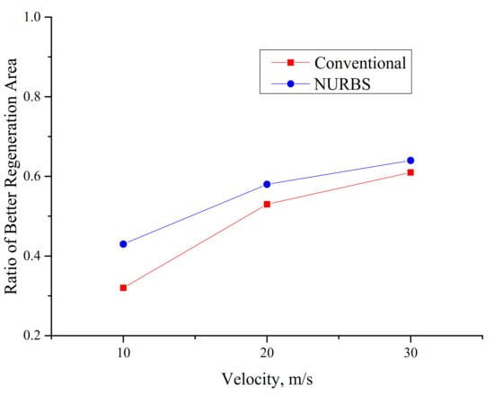
Figure 11.
Ratio comparison to determine the better-regeneration area.
Figure 11 shows that the ratio of the better-regeneration area is positively correlated with the velocity, indicating that the synergistic effect is improved under the condition of a high velocity. The main reason is that a high velocity accelerates convective heat transfer during flow in the process of particle combustion, which facilitates heat transfer.
Comparing the ratios of the better-regeneration area between these two cones, the monolith with the NURBS cone is superior to the monolith with the conventional cone. At a velocity of 10 m/s, the ratio of the monolith with the NURBS cone is approximately two times higher than that of the monolith with the conventional cone, demonstrating that the NURBS cone enhances the rate of regenerative combustion and optimizes the regeneration efficiency. Thus, the analysis of field synergy verifies the advantages of the NURBS cone structure.
4. Conclusions
In this paper, a regeneration test was carried out on axisymmetric monoliths loaded with particles, and the thermal distribution inside the monoliths was measured. Moreover, the synergy between the velocity and temperature fields in the monolith was studied via simulations. The main conclusions of this paper are as follows:
The test results revealed that the peak temperature in the loaded monolith with the conventional cone was higher, while the peak temperature in the loaded monolith with the NURBS cone was 31 °C lower. At the same position close to the boundary, the temperature in the loaded monolith with the NURBS cone was up to 60 °C higher than that in the loaded monolith with the conventional cone. The radial temperature gradient in the loaded monolith with the NURBS cone was 1.1 °C/mm lower than that in the loaded monolith with the conventional cone, which indicates that the thermal distribution in the loaded monolith with the NURBS cone was relatively more uniform.
Based on the experimental conditions, the regeneration process was simulated. The velocity and temperature fields in the regeneration process were analyzed through synergy simulations. The results demonstrated that the area with a higher regeneration synergy was located at the front and middle of the monolith and that the synergy gradually decreased from the front area to the back area.
A comparative study was carried out on heat transfer enhancement between the NURBS cone and the conventional cone. When the cosine value of angle between the velocity field and the temperature gradient was larger than 0.8, the regeneration performance was better, which was defined as the better regeneration area. The ratio of the regeneration area with better performance to that of the whole monolith was compared. It was found that the monolith with the NURBS cone had a higher ratio of better regeneration area, indicating that the NURBS cone can improve the combustion efficiency and has a better regeneration effect.
Author Contributions
Conceptualization, M.M. and L.D.; methodology, M.M.; validation, M.M.; formal analysis, M.M.; investigation, M.M. and L.D.; resources, M.M.; writing—original draft preparation, M.M.; writing—review and editing, L.D., B.C. and J.A.; supervision, M.M., B.C. and J.A.; project administration, B.C.; funding acquisition, M.M. All authors have read and agreed to the published version of the manuscript.
Funding
This research was funded by Shandong Provincial Natural Science Foundation, China, grant number: ZR2020QE164.
Institutional Review Board Statement
Not applicable.
Informed Consent Statement
Not applicable.
Data Availability Statement
Not applicable.
Acknowledgments
The authors are very thankful to the editor and referees for their valuable comments and suggestions for improving the paper.
Conflicts of Interest
The authors declare no conflict of interest.
References
- Apicella, B.; Mancaruso, E.; Russo, C.; Tregrossi, A.; Oliano, M.M.; Ciajolo, A.; Vaglieco, B.M. Effect of after-treatment systems on particulate matter emissions in diesel engine exhaust. Exp. Therm. Fluid Sci. 2020, 116, 110107. [Google Scholar] [CrossRef]
- Orihuela, M.P.; Chacartegui, R.; Gómez-Martín, A.; Ramírez-Rico, J.; Villanueva, J.A.B. Performance trends in wall-flow diesel particulate filters: Comparative analysis of their filtration efficiency and pressure drop. J. Clean. Prod. 2020, 260, 120863. [Google Scholar] [CrossRef]
- Xiao, G.; Li, B.; Tian, H.; Leng, X.; Long, W. Numerical study on flow and pressure drop characteristics of a novel type asymmetric wall-flow diesel particulate filter. Fuel 2020, 267, 117148. [Google Scholar] [CrossRef]
- Yamamoto, K.; Tajima, Y. Mechanism for pressure drop variation caused by filtration of diesel particulates. Int. J. Engine Res. 2021, 22, 632–639. [Google Scholar] [CrossRef]
- Suresh, A.; Yezerets, A.; Currier, N.; Clerc, J. Diesel Particulate Filter System-Effect of Critical Variables on the Regeneration Strategy Development and Optimization. SAE Int. J. Fuels Lubr. 2008, 1, 173–183. [Google Scholar] [CrossRef]
- Guan, B.; Zhan, R.; Lin, H.; Huang, Z. Review of the state-of-the-art of exhaust particulate filter technology in internal combustion engines. J. Environ. Manag. 2015, 154, 225–258. [Google Scholar] [CrossRef]
- Benjamin, S.; Roberts, C. Three-dimensional modelling of NOx and particulate traps using CFD: A porous medium approach. Appl. Math. Model. 2007, 31, 2446–2460. [Google Scholar] [CrossRef]
- Wang, D.-Y.; Tan, P.-Q.; Zhu, L.; Wang, Y.-H.; Hu, Z.-Y.; Lou, D.-M. Novel soot loading prediction model of diesel particulate filter based on collection mechanism and equivalent permeability. Fuel 2021, 286, 119409. [Google Scholar] [CrossRef]
- Landi, G.; Di Sarli, V.; Lisi, L. A Numerical Investigation of the Combined Effects of Initial Temperature and Catalyst Activity on the Dynamics of Soot Combustion in a Catalytic Diesel Particulate Filter. Top. Catal. 2021, 64, 270–287. [Google Scholar] [CrossRef]
- Yamamoto, K.; Yamauchi, K. Numerical simulation of continuously regenerating diesel particulate filter. Proc. Combust. Inst. 2013, 34, 3083–3090. [Google Scholar] [CrossRef]
- Fang, J.; Meng, Z.; Li, J.; Pu, Y.; Du, Y.; Li, J.; Jin, Z.; Chen, C.; Chase, G.G. The influence of ash on soot deposition and regeneration processes in diesel particular filter. Appl. Therm. Eng. 2017, 124, 633–640. [Google Scholar] [CrossRef]
- Chen, K.; Martirosyan, K.; Luss, D. Temperature gradients within a soot layer during DPF regeneration. Chem. Eng. Sci. 2011, 66, 2968–2973. [Google Scholar] [CrossRef]
- Psarianos, D.L. Development of a System for the Measurement of Soot Maldistribution and Pressure Drop Characteristics in Diesel Particulate Filter; University of Thessaly: Volos, Greece, 2002. [Google Scholar]
- Yu, M.; Luss, D. Inlet Cone Effect on Particulate Matter Deposition and Regeneration Temperature in a Diesel Particulate Filter. Ind. Eng. Chem. Res. 2012, 51, 3791–3800. [Google Scholar] [CrossRef]
- Mu, M.; Sjöblom, J.; Sharma, N.; Ström, H.; Li, X. Experimental Study on the Flow Field of Particles Deposited on a Gasoline Particulate Filter. Energies 2019, 12, 2701. [Google Scholar] [CrossRef]
- Zhang, Z.M. Nano/Microscale Heat Transfer; Springer Science & Business Media: Berlin, Germany, 2020. [Google Scholar]
- Liu, W.; Liu, Z.; Guo, Z. Physical quantity synergy in laminar flow field of convective heat transfer and analysis of heat transfer enhancement. Sci. Bull. 2009, 54, 3579–3586. [Google Scholar] [CrossRef]
- Liu, M. Influence Analysis of Different Structures on Temperature of Microwave Regeneration and Mechanism of Multi-Field Synergy in the Diesel Particulate Filter; Hunan University: Changsha, China, 2015. [Google Scholar]
- Nave, O. Analysis of the two-dimensional polydisperse liquid sprays in a laminar boundary layer flow using the similarity transformation method. Adv. Model. Simul. Eng. Sci. 2015, 2, 103. [Google Scholar] [CrossRef]
- Tao, W.; Guo, Z.; Wang, B. Field synergy principle for enhancing convective heat transfer-Its extension and numerical verifications. Int. J. Heat Mass Transf. 2002, 45, 3849–3856. [Google Scholar] [CrossRef]
- Tao, W.; He, Y.; Wang, Q.; Qu, Z.; Song, F. A unified analysis on enhancing single phase convective heat transfer with field synergy principle. Int. J. Heat Mass Transf. 2002, 45, 4871–4879. [Google Scholar] [CrossRef]
- Hamid, M.O.; Zhang, B.; Yang, L. Application of field synergy principle for optimization fluid flow and convective heat transfer in a tube bundle of a pre-heater. Energy 2014, 76, 241–253. [Google Scholar] [CrossRef]
- Mu, M.; Sjöblom, J.; Ström, H.; Li, X. Analysis of the Flow Field from Connection Cones to Monolith Reactors. Energies 2019, 12, 455. [Google Scholar] [CrossRef]
- Mu, M.; Li, X.; Qiu, Y.; Shi, Y. Study on a New Gasoline Particulate Filter Structure Based on the Nested Cylinder and Diversion Channel Plug. Energies 2019, 12, 2045. [Google Scholar] [CrossRef]
- Quan, Y.; Liu, Q.; Zhang, S.; Zhang, S. Comparison of the morphology, chemical composition and microstructure of cryptocrystalline graphite and carbon black. Appl. Surf. Sci. 2018, 445, 335–341. [Google Scholar] [CrossRef]
- Meng, Z.; Yang, D.; Yan, Y. Study of carbon black oxidation behavior under different heating rates. J. Therm. Anal. Calorim. 2014, 118, 551–559. [Google Scholar] [CrossRef]
- Tighe, C.; Twigg, M.; Hayhurst, A.; Dennis, J. The kinetics of oxidation of Diesel soots and a carbon black (Printex U) by O2 with reference to changes in both size and internal structure of the spherules during burnout. Carbon 2016, 107, 20–35. [Google Scholar] [CrossRef]
- Li, F.; Zhu, W.; He, H. Numerical optimization on microchannel flow and heat transfer performance based on field synergy principle. Int. J. Heat Mass Transf. 2019, 130, 375–385. [Google Scholar] [CrossRef]
- Cai, H.; Zhai, Y.; Chen, Y.; Liu, F.; Wang, H.; Xu, J. Numerical study on uniformity of temperature difference field in a spiral tube heat exchanger. Appl. Therm. Eng. 2021, 190, 116798. [Google Scholar] [CrossRef]
Publisher’s Note: MDPI stays neutral with regard to jurisdictional claims in published maps and institutional affiliations. |
© 2021 by the authors. Licensee MDPI, Basel, Switzerland. This article is an open access article distributed under the terms and conditions of the Creative Commons Attribution (CC BY) license (https://creativecommons.org/licenses/by/4.0/).