Abstract
The paper presents an elastic coupling with bolts and intermediary non-metallic elements, which allows for radial and axial deviation and can absorb shocks and torsional vibrations. The designed bolts have a particular shape of a circular area of a length equal to the width of the non-metallic element, a cylindrical area larger than the diameter of the cylindrical groove where the non-metallic elements are mounted, and a cylindrical area smaller than the threaded area to avoid stress concentrators and bolt breakage. The coupling represents a symmetrical piece, having two planes of symmetry. Therefore, the study of such a mechanical system can be considerably simplified considering the design and description of the repeating elements. The novelty of this coupling consists in the existence of an intermediate disc between two half-couplings (driving and driven half-coupling). The non-metallic elements with different shapes are made of different types of rubber, mounted on cylindrical bolts fixed by the driving half-coupling, transmitting the motion in both directions.
1. Introduction
In the field of engingeering, an elastic coupling can make a significant contribution when two machines work together [1,2,3,4,5,6,7,8]. For this reason, a particular study must be made for every practical application.
For elastic couplings with bolts, a large variety of solutions and materials are used depending on the demands and practical role. The solutions differ in dimension, design, shape of different elements, material, etc. Two of them are standardized: version N—normal; and version B—with spacer bush [9]. In these versions, the coupling is represented by a symmetrical device with two planes of symmetry. So, in this paper, the study of such a mechanical system can be considerably simplified considering the design and description of the repeating elements. In the same time, the manufacturing of a system with repeating elements is easier.
A wide variety of flexible couplings with rubber pins exists, in which the two half-couplings are different from each other [10,11].
There are many flexible bolt coupling solutions. They stand out for their simplicity, the two semi-couplings that constitute the coupling being identical [12]. The torque is transmitted in this case through the rubber sleeves covering the bolts.
A solution with washers or rubber bushes and studs is presented in [13,14]. In literature [15], it is studied a coupling which consists of two hubs: an elastic rubber element and bolts with self-locking nuts [13]. This type of coupling has been used for different machines as welding sets or compressors, as generally machineries have large driven inertias.
Two semi-couplings with bolts and rubber elements are present in Rupex coupling [16,17,18,19].
To connect shafts with a small parallel, angular, or axial misalignment, a coupling with a barrel element is used. These types are used for the liaison between an electric machine with working machines [20,21].
A solution for a coupling with holes on the circumference where cylindrical bolts are introduced is presented in [22]. The motion is transmitted from one engine to a shaft by bolts and rubber.
The marine coupling comprises a coupling body, with connecting pins, sleeve, screws, and rubber [23]. The maritime coupling is characterized by the materials used for the components. This coupling can be easily removed.
The quick-cushion rubber sleeve coupling for quick replacement includes half of the right-hand coupling assembly, a pin, an elastic sleeve, and a nut. The sleeve can be replaced easily and does not require co-axiality correction [24,25].
A possibility for the development of the paper is the modal analysis of such a system, in order to identify the vibration behavior [26,27,28,29,30,31]. In the coupling solutions existing in this moment, the non-metallic element is mounted in one of the semi-couplings in some bores specially processed for it, which implies a higher manufacturing/execution cost of that half-coupling, and in these conditions the non-metallic element is required at crushing, the torque capable of being transmitted by the coupling being determined by the condition of resistance to crushing of the non-metallic element. The maximum angular deviation that can be taken over by these couplings is if the shafts are collinear.
Elastic couplings are used to damp shocks caused by loads and to prevent dangerous vibrations. In addition, the elastic couplings allow some compensation for the inaccuracies of the mutual positioning of the shafts.
The non-metallic elastic elements used in the construction of couplings have very varied construction forms. In order to achieve couplings that satisfy, to the greatest extent, the conditions imposed by the operation, shapes are used that can modify the elasticity and damping properties.
In the case of dynamic loads, the elastic couplings with non-metallic elements accumulate and partially disperse the energy. By inserting the elastic couplings in the kinematic chains, the resonance range can be exceeded and the possibility of resonant vibrations is avoided.
The dampening capacity of the coupling refers to its property to disperse and to transform energy into deformation in heat. Damping occurs when there is a difference between the elastic load characteristic at charging and discharging the coupling.
The properties of rubber are: high elasticity, high damping capacity, constructive simplicity, and low price. The non-metallic intermediate elements lead to the electrical insulation of the connected shafts, but compared to the metallic intermediate elements, they give the coupling a lower durability, the transmitted torque being limited to low-medium values.
From the study carried out in this domain of elastic couplings using non-metallic elements, we found that there are elastic couplings with bolts having simple functional and designing principles.
Such couplings are produced by specialized companies, with international reputation, in a wide range of types and sizes. The studies made in this field are not numerous, which is why the use of a new type of coupling requires a careful analysis of its characteristics. The works published in the field are relatively few and books of Machine Design (courses or monographs) present only general notions regarding the design and manufacturing [1,2,3,4,5,6,7,8].
The paper proposes a coupling that has the following advantages:
- easy assembly and disassembly of non-metallic elements; easy assembly and disassembly of bolts;
- easy assembly and disassembly of intermediary disk;
- new constructive shapes of non-metallic elements which allow for non-metallic elements to relax, to be solicited and traction, and the capable moment to be transmitted from the condition of resistance of the non-metallic element besides crushing and shearing and torsion;
- by mounting the non-metallic element between the plates and not in bores processed in semi-couplings, it allows the non-metallic element to relax, this being required besides crushing, shearing, and traction; transmits the torque in both directions regardless of the chosen direction of rotation, as it does not become rigid;
- different elastic characteristics can be obtained, depending on the constructive shape and the material of the non-metallic elastic element; ensures the compensation of radial and angular deviations;
- the designed coupling has a simple construction, small overall dimensions and a low cost, compared to the classic ones with non-metallic elements and bolts.
2. Elastic Coupling Proposed Solution
The elastic coupling with cylindrical bolts and rubber intermediate elements presented in the paper is original, and the advantages of using such a coupling are presented below. The designed coupling was modeled 3D with the Autodesk Mechanical soft (Figure 1).
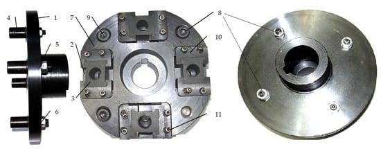
Figure 1.
Proposed elastic coupling with bolts and elastic intermediary elements. 1—driver half-coupling; 2—driven half-coupling; 3—elastic intermediary pieces; 4—bolts; 5—grower washers; 6—nuts; 7—intermediary disk; 8- screws; 9—pin; 10—metal supports; 11—screws.
The driver half-coupling 1 transmits the torque from the driver machine (electric motor) to the intermediary elastic elements 3, bolts 4, fixed rigidly on the input shaft (half-coupling 1), and further through an intermediary disc 7 to the output shaft (half- coupling 2). The exterior diameter of the coupling is De = 176 mm and the axial gauge is mm. The total weight of the coupling is mt = 3 kg. The total moment of inertia is 0.0213 kg m2.
In Figure 2 the constructive type of bolt is presented. The bolts 4 are fixed to the half-coupling 1.
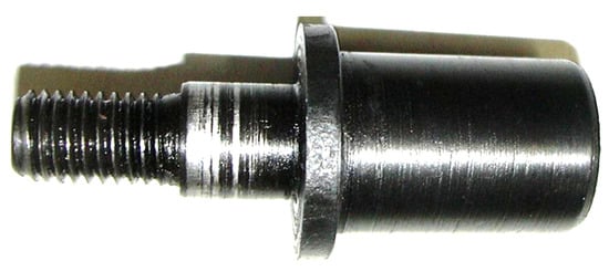
Figure 2.
Constructive shape of bolts.
The cylindrical areas of the bolt allows the centering of the bolt in the half-coupling 1 and represents a shoulder that prevents the axial displacement of the elastic element.
The cylindrical areas of the bolt, with a diameter larger than the diameter of the threaded area, aims to reduce the concentrating stress and breaking of the bolt.
The cylindrical area of the bolt with a diameter larger than the diameter of the threaded area has the role of reducing the stress at the transitions from the largest diameter to the diameter of the threaded area.
In Figure 3 the CAD model of plates 10 is presented, which are fixed to the intermediary disk 7 with two screws 11. Figure 4 presents different shapes of non-metallic element and their dimensions. The elasticity of the non-metallic element depends largely on its hardness (minimum 65° Sh).
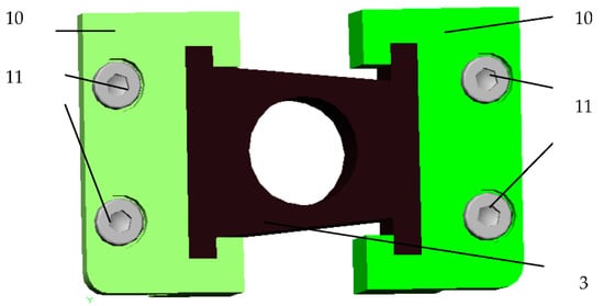
Figure 3.
Metallic plates 10, elastic intermediary piece 3, screws 11.
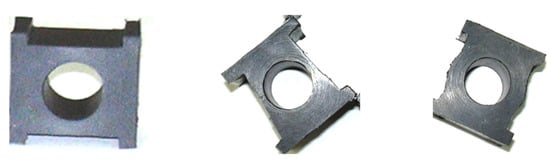
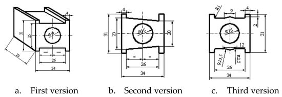
Figure 4.
Shapes of the non-metallic element.
Semi-couplings 1 and 2, the bolts 4, intermediary disc 7 and the metallic elements 10 were realized from improved OLC 45 steel. The mechanical characteristics of the C 45 steel are: density = 8.31 g/cm3, Young’s Modulus = 200 GPa, Poisssons’s Ratio = 0.287.
The mold used to obtain the three shapes of non-metallic elements is presented in Figure 5. The mold consists of the upper cover 1, the intermediate ring 2 (existing in three design versions: I, II, III, corresponding to the three shapes of the non-metallic elastic element) and the bolt 3, inserted by pressing in the lower cover 4.
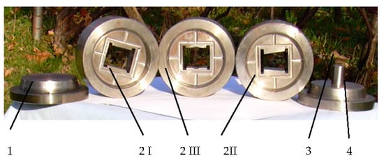
Figure 5.
Molds used to obtain the three versions of the non-metallic elements.
The experimental tests performed on the designed coupling were performance tests, as well as tests that followed the operation of the coupling.
Studied functional parameters are the torque at the entry shaft and at the output shaft.
Preliminary activities were required to carry out the experimental tests in good conditions, which consisted of:
- balancing the ends of the entrance and exit shafts of the stand;
- balancing the sensor applied on the coupling to determine the angular deformation of the coupling in the dynamic mode.
An activity prior to mounting the coupling on the stand considered the following stages:
- balancing the subassembly formed by the intermediate disc and plates;
- balancing the subassembly consisting of the intermediate disc, plates and the driven half-coupling;
- balancing the assembly consisting of the driving half-coupling, the intermediate disc, the plates, and the driven half-coupling.
The purposes of the experiments are:
- ➢
- measuring the torque at the input and at the output shaft;
- ➢
- measuring the relative deformation that appears between the two half-couplings;
- ➢
- obtaining the dynamic rigidity of the elastic coupling.
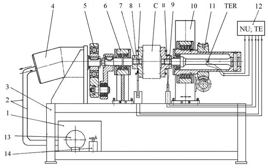
Figure 6.
Componence of experimental stand. The number are explaned in the text bellow.
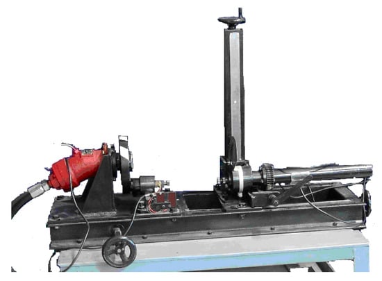
Figure 7.
Componence of experimental stand-detail.
The installation for the dynamic testing of the prototype (Figure 6) consists of the drive group 1, consisting of the electric motor and pump, supply pipes 2, frame 3, hydraulic motor 4, quadrilateral mechanism 5, support bearing 6, support flange 7, transducer pulse 8, the elastic test coupling C, the angle transducer 9, the adjustable support 10, the pre-tensioning system 11, the output shaft II, the measuring and recording system 12, the pressure gauge 13, the hydraulic regulator 14, and the TER resistive electrical transducers.
The dimensions of the existing stand in the endowment of the department at the moment of performing the test were: width l = 1 m, length L = 1.5 m, and height H = 1.5 m.
The measuring system 12 consists of a universal pulse NO counter, which counts the pulses detected by the pulse transducer 8 and the TE electronic tensometer, which indicates the value of the specific deformation. The power circuit is hydraulically driven from the drive group 1, and by means of the supply pipes 2 the hydraulic motor 4 is supplied. The hydraulic motor drives, by means of the quadrilateral mechanism 5, the inlet drive shaft I supported by the support bearing 6. Support flange 7 is fixed by means of grooves to the end of the input drive shaft I. The elastic test coupling C (half-coupling I) is attached to one end of the flange 7, its other end being fixed by grooves to the flange of the output shaft II. By means of the pre-tensioning system 11, the output shaft II is fixed on the adjustable support 10, which can move in two directions orthogonal to the frame of the frame 3, thus performing the coupling test.
To perform the dynamic coupling test, the following steps are performed: check the position and correct operation of the prototype C (Figure 6) and of the angular transducer 9; before starting the test, move the support bearing 6 to the desired position to achieve the amplitude of the variable moment; the power circuit is rotated until the quadrilateral mechanism 5 reaches neutral, thus being blocked. By actuating the pretensioning system 11, the prototype is twisted, the static torque being created in the power circuit. This moment produces a deformation, which is measured by means of the output shaft II and the TER electroresistive transducers glued to the shaft; when the desired stress cycle is obtained, the action on the prestressing system 11 ceases. The stress cycle can also be identified by means of the indicator with which the test installation is provided; by actuating the hydraulic regulator 14 (Figure 6), the pressure in the hydraulic circuit is regulated, thus obtaining the desired test frequency. The manometer 13 indicates the variation of the pressure in the hydraulic circuit, and the pulse transducer 8 together with the universal numerator in the measuring and recording system 12 signals the value of the frequency; depending on the deformation value, from the torsion sensor calibration diagram, the values of the maximum torque and the amplitude of the oscillating moment are estimated. Using the angular transducer 9 and the measuring and recording system 12, the elastic deformation of the tested coupling is measured and the rigidity of the tested coupling is calculated.
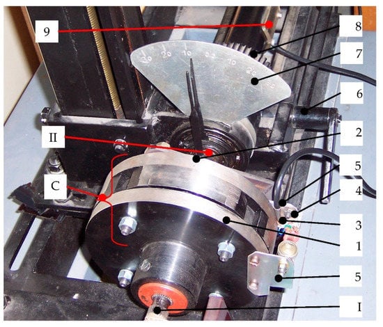
Figure 8.
Experimental stand for the study of elastic coupling.
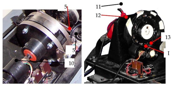
Figure 9.
Experimental stand for the study of elastic coupling-details.
To determine the desired parameters, the installation is equipped with transducers (pulse transducer, angle transducer), measuring and control devices, devices for visualizing the studied phenomenon.
In order to determine the angular deformations of the coupling in a dynamic regime, it was necessary to use a deformation sensor, which was applied on the driven half-coupling 2. The deformation sensor 3 was glued on a metal plate 4 made of spring steel, fixed to a metal plate 5 (bent in the shape of the letter “L”), by means of two screws and two nuts (Figure 8).
- Figure 8 shows the coupling C to be tested mounted on the stand, the input (I) and output shafts (II), the conductive and driven half-coupling 2, the deformation measuring sensor 3 fixed on a metal plate 4 in the shape of the letter L which is attached to the half-coupling 2, where: 4—metal lamella, 5—metal plate fixed to the half-coupling 2, 6—crank, 7—angular transducer, 8—prestressing system, 9—TER represents resistive electrical transducers, 10—support bearing, 11—hydraulic motor, and 12 -, 13 -, and 14—the hydraulic regulator of the stand.
- The driving half-coupling is mounted on the input shaft I of the test stage, and the driven half-coupling on the output shaft II of the stand.
- The electronic equipment necessary for the dynamic tests of the tested coupling consists of two tensometric bridges and an oscilloscope. In Figure 9, item 11 represents the tensometric bridges that measure the variation of the relative rotation angle between the half-couplings and the torque at the output shaft and 13 is the oscillograph that records the torque at the output shaft as a function of the relative rotation angle between the half-couplings.
The purposes of the experiments are:
- ➢
- measuring the torque at the input and at the output shaft;
- ➢
- measuring the relative deformation that appears between the two half-couplings;
- ➢
- obtaining the dynamic rigidity of the elastic coupling.
The coupling tests were performed in dynamic mode, taking into account two distinct situations: (1) the two input shaft and output shaft mounted collinearly; (2) the two input shaft-output shafts radially offset by 0.4 mm. In these situations, the variation of the torque at the output shaft was analyzed according to the angular deformation between the two half-couplings, a deformation that occurred as a result of the loading and unloading of the coupling.
First, the coupling was tested in a dynamic regime without radial misalignment of the input and output shafts. The maximum relative rotation angle between the two half-couplings being of maximum 2.2° at a maximum moment at the output shaft of 44 Nm. The second dynamic determination was performed with the input and output shafts radial offset by 0.5 mm. The radial displacement between the input and output shafts was obtained by the radial displacement of the output shaft.
By actuating the crank, the dynamic loading and unloading of the prototype was performed in case of radial misalignment of the two input shafts, the oscilloscope recording the variation of the angular deformation and the torque at the output shaft II.
The data obtained after measurement are presented in Table 1. The dynamic rigidity of the tested couplings varies depending on the relative value of the angle between the 2 half-couplings. In the experiment a radial deviation of Δr = 0.4 mm is considered.

Table 1.
Dynamic rigidity of tested prototype with radial deviation Δr = 0.4 mm, input-output shafts, in dynamic regime.
The dynamic rigidity of elastic coupling is defined as the ratio of the torque obtained in dynamic regime to the relative rotation angle between the semi-couplings. The medium dynamic rigidity of coupling is obtained with relation:
where n represents the number of dates on graphic and kdynamic i is the partial dynamic rigidity same of each dates
After processing the experimental data obtained with a radial misalignment by 0.4 mm between the input and output shaft, the torque diagram is obtained. The variation of the torque and the hysteresis of the elastic non-metallic element can be seen in Figure 10.
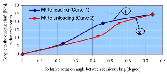
Figure 10.
The dynamic variation of torque to the output shaft depending on the relative rotation angle between the two half-couplings (radial deviation Δr = 0.4 mm).
The coupling was also tested in dynamic regime without radial misalignment of the input and output shafts, the maximum relative rotation angle between the two half-couplings being of maximum 2.2° at a maximum moment at the output shaft of 44 Nm.
The rigidity of the coupling is represented by the ratio between the torque and the relative angular deformation between the half-couplings.
The damping causes the moment-deformation curve to change into a hysteresis curve. The most important factors that influence the dynamic rigidity are: the operating temperature of the coupling, the average torque, the frequency, and the amplitude of the torque. Heating of the elastic elements can occur due to the ambient temperature or due to internal friction under the influence of the torque. Due to the increase of the temperature of the elastic elements, the relative angular deformations of the half-couplings increases and both the static and the dynamic rigidity decreases. As the temperature increases, the modulus of elasticity decreases. The rubber chosen to manufacture the non-metallic elements is resistant to oils or diesel fuel.
The nonlinear characteristics of nonmetallic elements also depend on their geometry.
Table 2 shows the dynamic rigidity of the tested coupling calculated when the input and output shafts are parallel, with a radial deviation of Δr = 0.4 mm.
Table 2.
Medium rigidity of tested coupling with radial deviation Δr = 0.4 mm by input-output shafts, in dynamic regime.
3. Discussion
Before testing the elastic coupling in dynamic regime, the input and output shafts of the stand were balanced, the coupling was balanced, and a sensor was applied to the coupling. During the experiments, progressive loading and unloading was performed. Deformations and stress in the non-metallic material depend on the loading torque.
The rigidity depends as well on the torque Mt and on the relative rotation angle between the half-couplings. After testing the coupling in dynamic mode, the elastic characteristic of the coupling was obtained.
The shape of the elastic element and the material from which it is obtained, determine the elastic characteristic. The maximum angular deformation between the two half-couplings is 0.7407340 degrees when the input and output shafts have a deviation between axes by 0.4 mm. The maximum relative angular deformation between the two half-couplings is from when no radial misalignment is introduced.
Value of medium dynamic rigidity of coupling, on the first zone of testing is 34,585 Nmm/degree. The value of medium dynamic rigidity of coupling, on the second zone of testing is 31,979 Nmm/degree. The value of mean dynamic rigidity of coupling is 33,282 N.mm/degree. If the two shafts are collinearly, the medium dynamic rigidity of coupling is 18,243.25 Nmm/degree.
From the comparison of the results obtained in the dynamic test without radial offset and with radial offset, it was found that the dynamic stiffness of the coupling is higher in the dynamic regime. From the comparison of the results obtained in the dynamic test without radial misalignment (input-output shafts being collinear) with the results obtained in the dynamic test with radial misalignment (input-output shafts being non-collinear) it is found that the maximum relative angular deformation between two half-couplings is from when no radial misalignment is introduced and from when the input-output shafts are radial offset by mm.
The damping capacity of torsional shocks for an elastic coupling with bolts and non-metallic intermediate elements help the system to convert a part of energy into heat and the rest is transformed into deformation energy.
4. Conclusions
For this prototype, depending on the design and material of the elastic element, regardless of whether the input-output shafts are non-collinear, can be obtained different elastic characteristics and different partial and average dynamic.
The experimental dynamic stiffness obtained in the case of radial misalignment between input-output shafts is higher as in the case when input-output shafts are collinear. During the experimental testing of this coupling, a silent operation of the prototype is detected.
It was found that the dynamic average stiffness, if the input-output shafts are a radially deviation of 0.4 mm, is lower than the static average stiffness, if the input-output shafts are collinear.
Therefore, it is found that in dynamic regime without radial misalignment the tested design version takes a maximum angular deformation of relative rotation between the two half-couplings greater than the maximum angular deformation of relative rotation between the two semi-couplings in dynamic regime with radial misalignment.
Figure 10 shows the nonlinear elastic characteristic of the coupling at loading and unloading with load, the hysteresis of the coupling, as well as the fact that the coupling has variable rigidity.
The designed coupling takes over larger angular deviations in the dynamic regime without misalignment than the classic couplings in the current study for the constructive dimension at which it was designed.
During the dynamic experimental testing of prototype, the following were found: different elastic characteristics can be obtained, depending on the constructive shape and the material of the non-metallic element; and no vibrations or radial beats occurred, which confirms a good design and a good execution.
Author Contributions
Conceptualization, M.G., I.-M.G., S.V., P.N.B.; methodology, M.G., I.-M.G., S.V.; software, M.G., I.-M.G. and P.N.B.; validation, M.G., I.-M.G., and S.V.; formal analysis, M.G., I.-M.G., and P.N.B.; investigation M.G.; resources, M.G., S.V. and P.N.B.; data curation, I.-M.G., M.G. and P.N.B.; writing—original draft preparation, M.G.; writing—review and editing, M.G., I.-M.G., S.V.; visualization, M.G. and S.V.; supervision, I.-M.G., M.G., S.V. and P.N.B. All authors have read and agreed to the published version of the manuscript.
Funding
This research received no external funding.
Institutional Review Board Statement
Not applicable.
Informed Consent Statement
Not applicable.
Data Availability Statement
Not applicable.
Acknowledgments
We want to thank the reviewers who have read the manuscript carefully and have proposed pertinent corrections that have led to an improvement in our manuscript.
Conflicts of Interest
The authors declare no conflict of interest.
References
- Budynas, R.; Nisbett, K. Mechanical Engineering Design, 10th ed.; McGraw-Hill: New York, NY, USA, 2014. [Google Scholar]
- Dieter, G.; Schmidt, L. Engineering Design, 5th ed.; McGraw-Hill Education: New York, NY, USA, 2012. [Google Scholar]
- Mott, R.; Vavrek, E.; Wang, J. Machine Elements in Mechanical Design, 6th ed.; Pearson: London, UK, 2017. [Google Scholar]
- Mzsyka, D. Machines & Mechanisms: Applied Kinematic Analysis, 4th ed.; Pearson: London, UK, 2010. [Google Scholar]
- Oberg, E. Machinery’s Handbook Toolbox, 31st ed.; Industrial Press Inc.: Norwalk, CT, USA, 2020. [Google Scholar]
- Parmlez, R. Mechanical Components, 1st ed.; McGraw-Hill: New York, NY, USA, 2000. [Google Scholar]
- Norton, R. Design of Machinery, 5th ed.; McGraw-Hill: New York, NY, USA, 2011. [Google Scholar]
- Spotts, M.; Shoup, T.; Hornberger, L. Design of Machine Elements, 8th ed.; Pearson: New Delhi, India, 2003. [Google Scholar]
- Standard STAS 5982. Flexible Coupling with Bolts. Available online: https://www.etansari-mecanice-pompe.ro/cat/cuplaje-elastice-mecanice-permanente/cuplaje-mobile-elastice-cu-bolturi-element-elastic-din-cauciuc/ (accessed on 20 October 2020).
- Flexible Couplings with Rubber Studs. Available online: http://www.velhightech.com/Documents/ME8593%20Design%20of%20Machine%20Elements.pdf (accessed on 20 October 2020).
- A Flexible Coupling with Stifts and Washers or Rubber Bushes. Available online: https://www.kdkce.edu.in/upload//Machine%20elements,%20Power%20Transmission%20Devices.pdf (accessed on 20 October 2020).
- Guardian-Couplings. Available online: https://www.guardiancouplings.com/-/media/Files/Literatur/Brand/guardian-couplings/related/brochures/p-7733-gc.ashx (accessed on 20 October 2020).
- RUPEX® Couplings. Available online: https://www.flender.com/en/Products/Couplings/RUPEX-Pin-and-Bush-Coupling/p/ATN03101 (accessed on 26 October 2020).
- Module 5 Couplings. A Typical Flexible Coupling with Rubber Bushings. Available online: https://nptel.ac.in/content/storage2/courses/112105125/pdf/module-5%20lesson-2.pdf (accessed on 20 October 2020).
- Flexible-Coupling. Available online: https://www.comintec.com/en/project/flexible-coupling (accessed on 20 October 2020).
- Construction-Installation-and-Maintenance-of-Flexible-Couplings.pdf. Available online: https://practicalmaintenance.net/wp-content/uploads/Construction-Installation-and-Maintenance-of-Flexible-Couplings.pdf (accessed on 26 October 2020).
- Rupex-Claw-Couplings. Available online: https://www.geartech.no/en/products/transmission/shaft-couplings/rupex-claw-couplings/ (accessed on 26 October 2020).
- A Flange Coupling and Non-Metallic Barrel elements. Available online: https://www.researchgate.net/publication/331154663_Design_and_Analysis_of_Bushed_Pin_Flexible_Co.upling?enrichId=rgreq-10a027bed8d6a339a6fd0b9e3c43d0b4-XXX&enrichSource=Y292ZXJQYWdlOzMzMTE1NDY2MztBUzo3MjY5OTMwMTY0Nzk3NDRAMTU1MDM0MDA1MDY4Ng%3D%3D&el=1_x_2&_esc=publicationCoverPdf (accessed on 25 October 2020).
- Patent SU 1262417 A1. Elastic Coupling with Rubber-Bushed Studs. Available online: https://worldwide.espacenet.com/publicationDetails/biblio?II=15&ND=3&adjacent=true&locale=en_EP&FT=D&date=19861007&CC=SU&NR=1262147A1&KC=A1 (accessed on 10 November 2020).
- Patent CN 103925303/16.07.2014. Rubber-Cushioned Sleeve Bearing Coupling Fast to Replace. Patent CN 106321676A, 11 January 2017. Elastic Coupling. Available online: https://worldwide.espacenet.com/patent/search/family/057733218/publication/CN106321676A?q=elastic%20coupling%20rubber%20bolt (accessed on 11 November 2020).
- Timur, C.K. Design and Analysis of Bushed Pin Flexible Coupling. IJARESM 2017, 5, 38–44. [Google Scholar]
- Prodănescu, G.S.; Iliuc, I. Elastic Coupling, with Elastic, Non-Metallic, Radial, Discrete Elements. Patent RO 116430 (B1), 30 January 2001. [Google Scholar]
- Hangzhou, X.K. Transmission Machinery Co Ltd. Maritime Coupling. Utility Model. CN 203847581U, 24 September 2014. [Google Scholar]
- Herwarth, R. Elastic Coupling. U.S. Patent 2924082A, 9 February 1960. [Google Scholar]
- Vlase, S. A Method of Eliminating Lagrangian-Multipliers from the Equation of Motion of Interconnected Mechanical Systems. J. Appl. Mech. Trans. ASME 1987, 54, 235–237. [Google Scholar] [CrossRef]
- Radu, M. Theoretical and Experimental Studies as Concerns Couplings with Nonmetallic Elastic Elements. Ph.D. Thesis, Transylvania University of Brasov, Brașov, Romania, 2005. [Google Scholar]
- Autodesk Mechanical Desktop 6 Power Pack. Available online: https://usermanual.wiki (accessed on 26 October 2020).
- Martini, A.; Troncossi, M.; Vincenzi, N. Structural and elastodynamic analysis of rotary transfer machines by Finite Element model. J. Serbian Soc. Comput. Mech. 2017, 11, 1–16. [Google Scholar] [CrossRef]
- Manzato, S.; Peeters, B.; Osgood, R.; Luczak, M. Wind turbine model validation by full-scale vibration test. In Proceedings of the European Wind Energy Conference (EWEC), Warsaw, Poland, 20–23 April 2010. [Google Scholar]
- Troncossi, M.; Taddia, S.; Rivola, A.; Martini, A. Experimental Characterization of a High-Damping Viscoelastic Material Enclosed in Carbon Fiber Reinforced Polymer Components. Appl. Sci. 2020, 10, 6193. [Google Scholar] [CrossRef]
- Carden, E.P.; Lindblad, M. Operational modal analysis of torsional modes in rotating machinery. J. Eng. Gas Turbines Power 2015, 137, 022501. [Google Scholar] [CrossRef]
Publisher’s Note: MDPI stays neutral with regard to jurisdictional claims in published maps and institutional affiliations. |
© 2021 by the authors. Licensee MDPI, Basel, Switzerland. This article is an open access article distributed under the terms and conditions of the Creative Commons Attribution (CC BY) license (https://creativecommons.org/licenses/by/4.0/).