Article

A Method for Calculating Soil Deformation Induced by Shielded Tunneling in Ground Stratum with Cavities

1
Department of Civil Engineering, Zhejiang University City College, Hangzhou 310015, China
2
School of Civil Engineering and Architecture, Anhui University of Science and Technology, Huainan 232001, China
3
College of Civil Engineering and Architecture, Zhejiang University, Hangzhou 310027, China
*
Author to whom correspondence should be addressed.
Symmetry 2021, 13(6), 1048; https://doi.org/10.3390/sym13061048
Submission received: 20 April 2021 / Revised: 4 June 2021 / Accepted: 7 June 2021 / Published: 10 June 2021

Abstract

:
The existence of cavities in shallow ground strata is one of the important causes of urban road collapse under the disturbance of tunnel excavation. Thus, this paper discusses the convergent deformation mode of ellipsoidal cavities. To this end, the convergent deformation of a cavity and the overall displacement of a tunnel were comprehensively examined. A three-dimensional symmetrical calculation model of the soil deformation under the combined action of the tunnel and the cavity was also established. Moreover, three-dimensional formulas for calculating the soil deformation and the surface settlement of the upper part of the tunnel and the cavity were derived. The influence of the different positions of the cavity on the surface settlement of the upper part of the tunnel was also examined. Further, the change in the soil settlement with the direction of the tunnel excavation and the depth of burial of the cavity was analyzed. The results show that the calculated settlement curves are consistent with the ones reported in the related literature. The cavity can also aggravate the surface settlement and deformation of the soil caused by the tunnel excavation. When the cavity is directly above the tunnel, the surface settlement curve is symmetrically distributed. As the position of the cavity changes, the overall settlement curve shifts to the direction of the cavity, showing asymmetry. Additionally, along the x-axis direction of the shielded tunnel, the surface settlement gradually increases to a limit value with a decrease in x and slowly declines to zero as x rises. Finally, along the depth of burial of the cavity, the settlement of the soil continues to enlarge; also, the growth rate of the soil settlement continues to increase further at positions closer to the cavity and the tunnel until it reaches a critical maximum.

1. Introduction

In recent years, there have been frequent ground collapse accidents caused by the excavation of shallow urban tunnels owing to the existence of a large number of cavities in the shallow space. Cavities are a common undesirable geological body in underground engineering, and from the viewpoint of formation, they are divided into natural geological cavities and artificially formed cavities. In Beijing, Chengdu, and other locations where the ground is dominated by silt, silty clay, sand, and pebbles, many stratum cavities are usually found during the construction of subways. Some cavities are formed before the excavation of subways, and some are formed under the disturbance of tunnel construction. The construction of shielded tunnels in the stratum with cavities can easily give rise to engineering accidents such as cavity collapse and water gushing [1]. The existence of cavities can affect the safety of the existing tunnels [2,3] and can inevitably aggravate soil deformation, which poses a serious threat to the surface environment and buildings. Therefore, studying the law of the soil displacement caused by the construction of shielded tunnels in strata with cavities is of great significance.
Aiming at the problem of soil deformation caused by tunnel excavation in the strata containing cavities, the existing research methods chiefly include numerical simulation [2,4,5,6], model test [3,7,8], and theoretical calculation [9,10,11,12]. The contents of the research have largely focused on the failure mechanism of surface collapse caused by the development of cavity deformation [5,6,13,14,15], the influence of the existence of cavities on the stress on and the failure mode of tunnel segments [2,3,16], the law of the surface settlement under the combined influence of cavities and tunnel excavation [4,7,8,10,11,12], and the change law of the stress field in the formation with cavities [9,17]. Among them, Cai et al. [4] and Zhang et al. [7] have generally used model tests and numerical simulation. In general, the research on the theoretical solution is scarce, and there are some shortcomings in this context, as explained in the following. Therefore, it is necessary to further study the theoretical method for calculating the soil deformation of the strata containing cavities under the influence of shielded tunneling.
On the basis of the random medium theory and the mirror image method, this paper uses the three-dimensional soil deformation calculation method proposed by Qi et al. [18] and Wei [19] to derive the calculation formulas for the displacement of the upper soil caused by cavity deformation and shielded tunneling. It is proposed that the cavity is affected by tunnel excavation largely in the convergent deformation and overall movement. Thus, this work devises a calculation method for measuring the deformation of the upper stratum under the combined influence of tunnel excavation, cavity movement, and convergent deformation. Moreover, the description method of cavity shape is simplified [20] and the law of the ground settlement at different positions of the cavity is examined. Finally, the variation in the soil settlement with the direction of the tunnel excavation and depth of burial of the cavity is analyzed.

2. Insufficiency of Existing Research and Description of Improvement

2.1. Shortcomings and Difficulties of Existing Research

The existing research has some shortcomings and faces a number of difficulties as follows:
  • First, the mechanism of cavity deformation is complex and influenced by many factors, making it difficult to accurately predict it.
  • Second, the shape of cavities differs in actual projects, and it is necessary to establish a suitable and reasonable theoretical calculation model.
  • Third, because cavities are located below the surface, the convergence of the cavities is difficult to measure, and there is a lack of relevant empirical values.
  • Fourth, there are few theoretical solutions to the ground settlement and the soil displacement caused by tunnel excavation in the ground strata containing cavities. Among them, Yang et al. [10] studied the theoretical solution through the Schwarz alternating method and the elastic solution for the complex variable function. However, they could not examine the distribution law of the surface settlement along the direction of the shielded tunneling and did not derive the calculation formula for the deformation of the soil layer at different depths. In addition, complexity and cumbersome calculations are not conducive to popularization and application.

2.2. Instructions for Remedying Shortcomings

The following are proposed so as to remedy the abovementioned shortcomings:
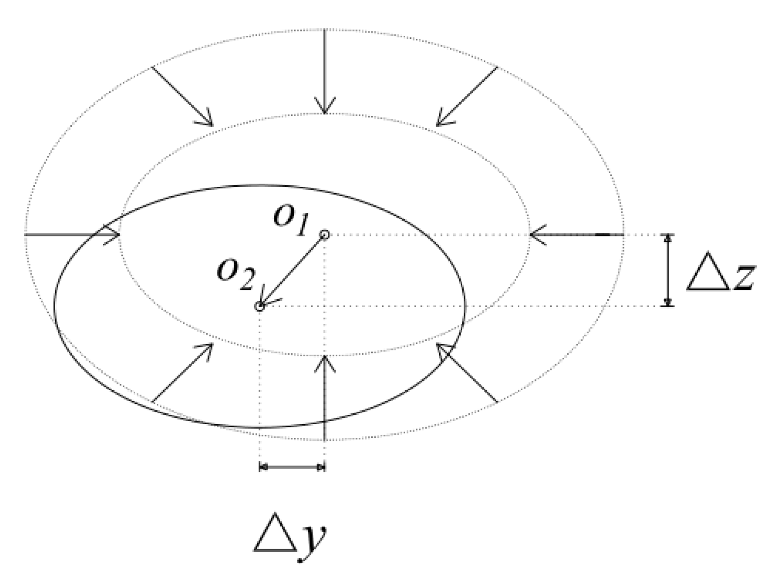
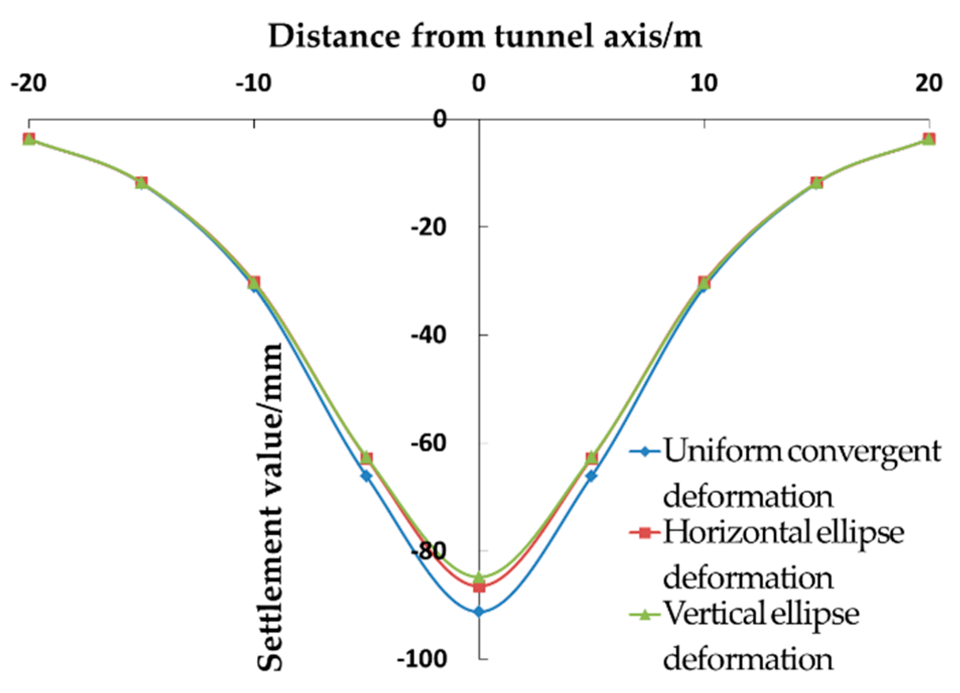
  • First, this work believes that the impact of tunnel excavation on the cavity chiefly includes the overall movement and the convergence of the boundary. In order to effectively estimate the surface settlement and the displacement of the upper soil caused by the cavity, three symmetrical modes of shape convergence are proposed: the uniform convergence, the horizontal elliptical convergence, and the vertical elliptical convergence.
  • Second, in actual engineering, cavities have their own stability due to their long-term existence and deformation development. Tian [21] proposed the concept of “cavity shell” and believed that cavities can maintain their stability under normal conditions but lose their stability and deform when they are disturbed by the outside world. Although the reason for the formation of cavities is complex, and their shape is irregular, for a cavity with stable surrounding rock, its shape should satisfy the reasonable distribution of the surrounding rock force. Moreover, because the surrounding stress is slightly concentrated, the stability of the circular hole-shaped cavities is higher than that of other linear cavities with angles. Therefore, in the related literature, cavities have mostly been simplified into spherical or ellipsoidal ones. Thus, this paper chiefly discusses the deformation mode of an ellipsoidal cavity and the soil settlement caused by it.
  • Third, this work introduces the concept of the convergence rate of the cavity (εs) to express the size of the convergence of a cavity. On the basis of the research results of Loganathan [22], it is proposed that the convergence rate of the cavity can be estimated according to the relative position of the tunnel and the loss rate of the soil (ηs) caused by the tunnel excavation.
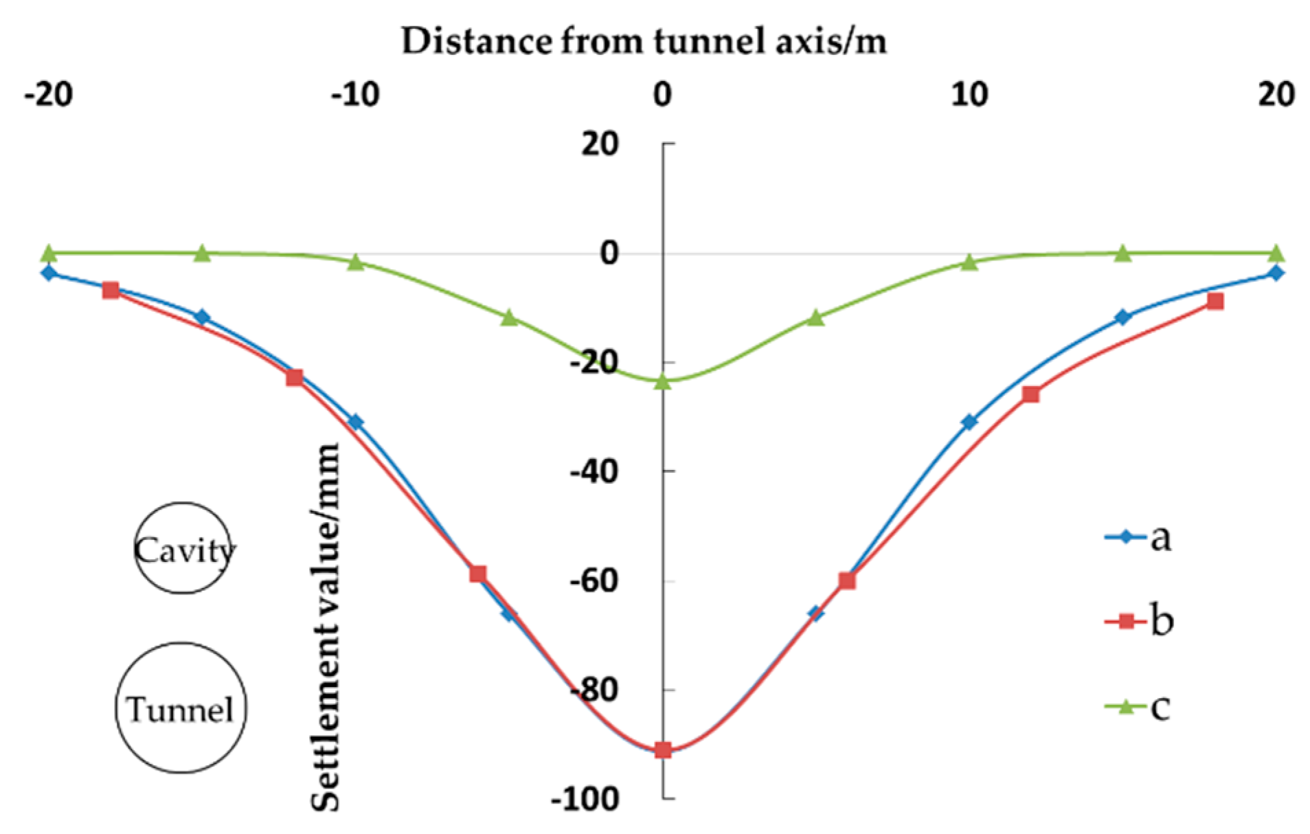
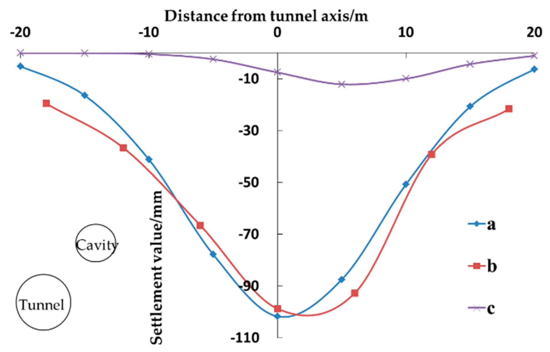
  • Fourth, this paper studies the variation in the soil settlement value with the direction of the tunnel excavation and the depth of burial of the cavity.

3. Methodology

3.1. Introduction of Our Research Ideas and Calculation Models

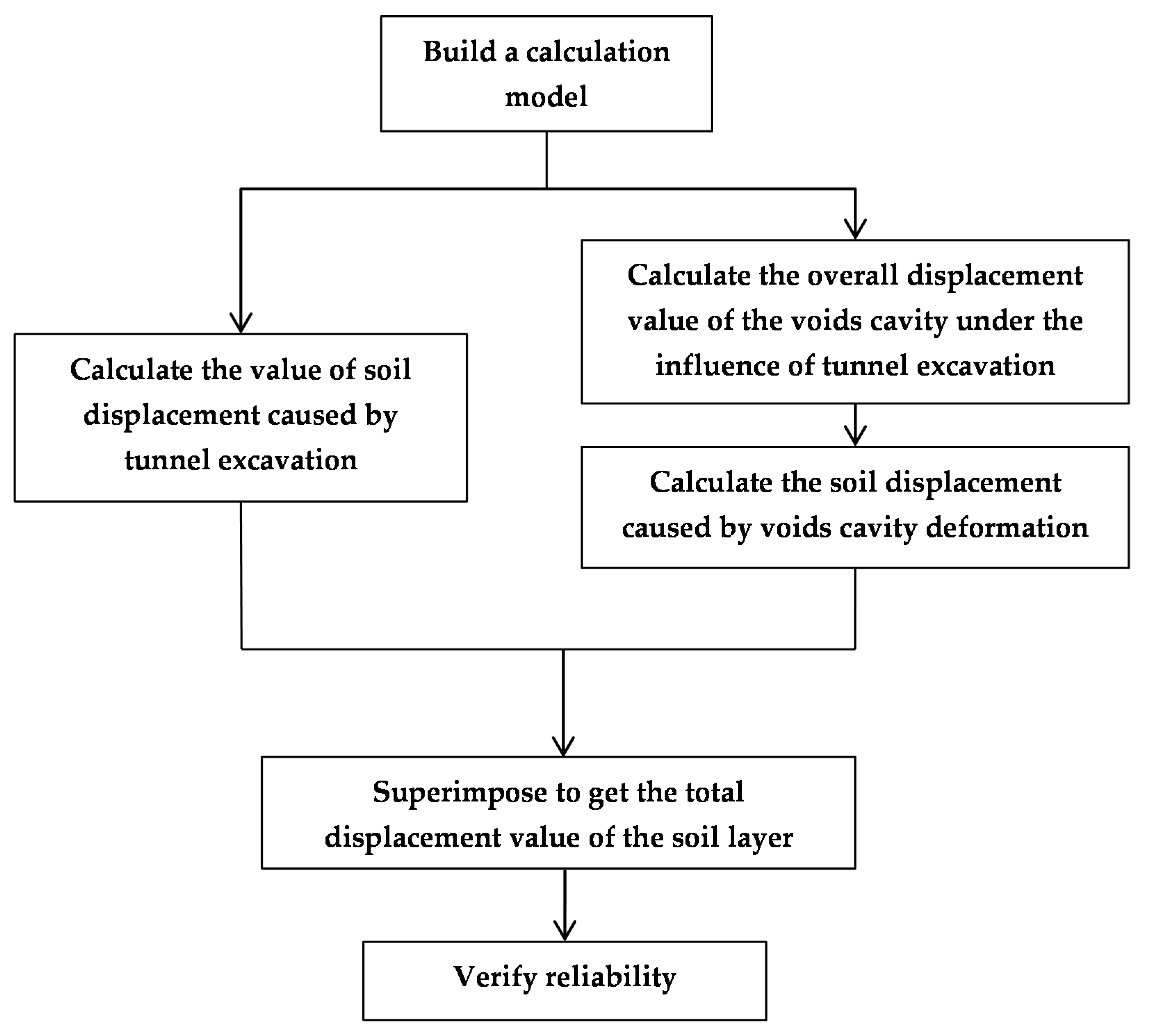
3.1.1. Research Ideas

As shown in Figure 1, the proposed method includes the following steps:
  • A theoretical calculation model is established.
  • The soil displacement value caused by the excavation of the shielded tunnel is calculated.
  • The overall displacement and convergence of the cavity are considered, and the soil displacement value caused by the cavity deformation is calculated.
  • The soil displacement values of steps 2 and 3 are superimposed to determine the total displacement value of the soil layer.
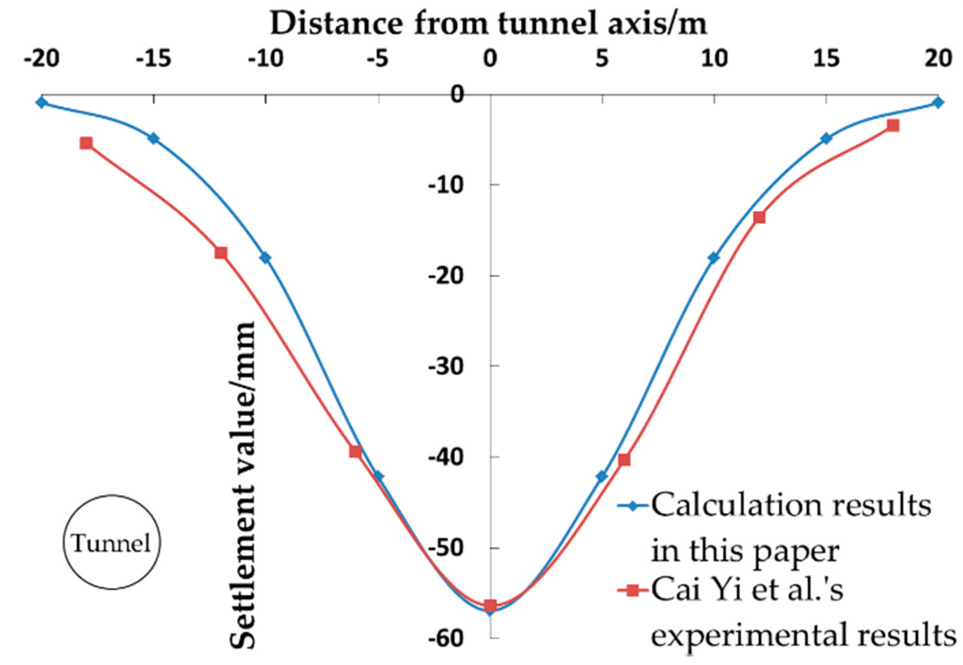
  • The test data are combined for reliability verification.

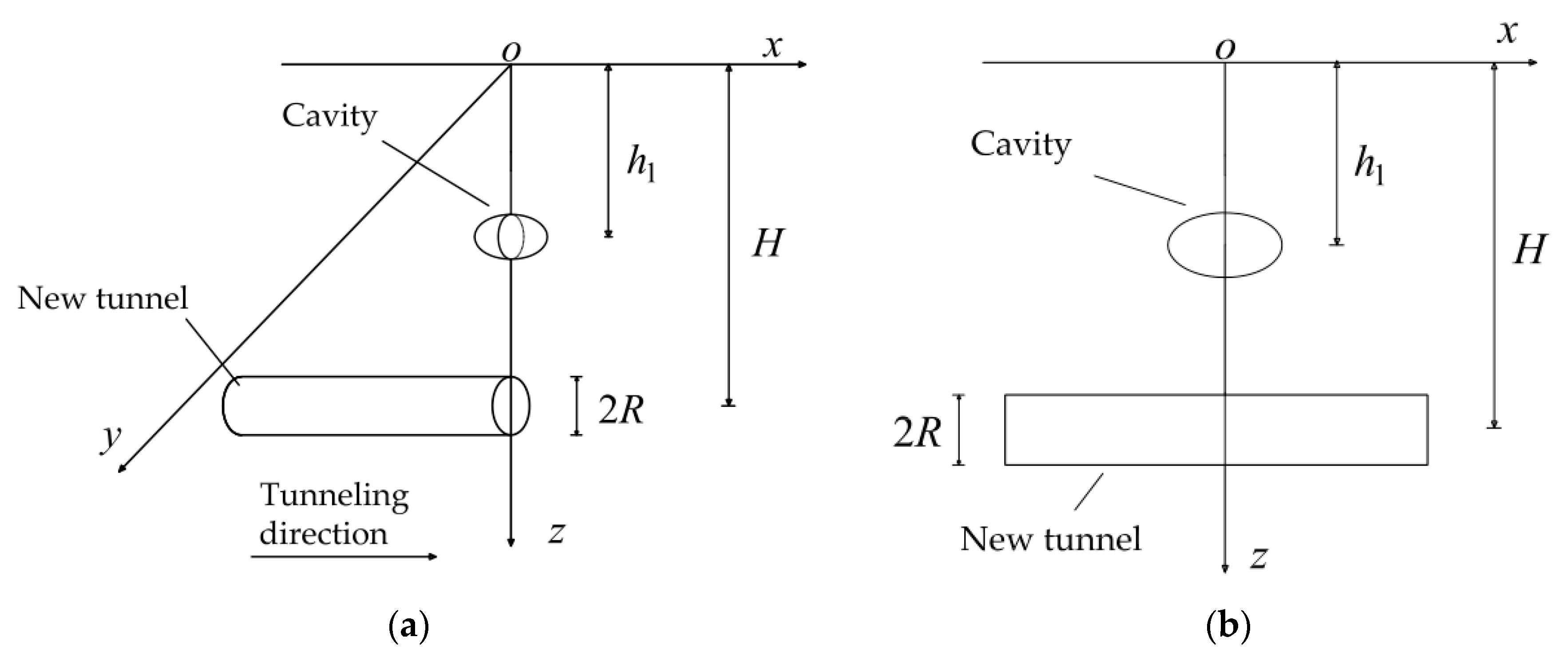
3.1.2. Building Calculation Model

Figure 2 depicts the developed three-dimensional symmetrical calculation model. Assuming that the tunnel is driven along the x-axis and is symmetrical about the xoz plane, the radius of the tunnel excavation and the depth of the tunnel axis are indicated by R and H respectively. There is an ellipsoidal cavity directly above the tunnel; it is worth noting that a sphere is a special case of an ellipsoid. The center of the ellipsoidal cavity lies on the z-axis, and h1 denotes the depth of the center. Ra, Rb, and Rc represent the radius of the ellipsoidal cavity along the x-axis, y-axis, and z-axis respectively.

3.2. Calculation of Soil Deformation Caused by Tunnel Excavation

A. Verruijt and J. R. Booker [23] assumed that the soil movement caused by shield construction is a uniform radial movement model, and the soil is a linear elastic material. Wei Gang [24] referred to the research methods of N. Loganathan and H.G Poulos [22] and modified the calculation formulas of A. Verruijt and J.R. Booker [23] to obtain a two-dimensional solution of soil deformation. On the basis of the two-dimensional solution, Wei Gang [19] considered the change of the soil loss rate with the shield tunneling distance and derived a three-dimensional solution of the soil deformation.
In order to calculate the vertical deformation of the soil (Uz-s) and the lateral deformation of the soil (Uy-s) caused by the shielded tunneling at any point (x, y, z), this paper refers to the three-dimensional solution for the soil deformation proposed in [19]:
U y s = { 1 y 2 + ( H z ) 2 + 1 y 2 + ( H + z ) 2 4 z ( H + z ) [ y 2 + ( H + z ) 2 ] 2 } η s B R 2 y 4 H H + d ( 1 x x 2 + H 2 ) exp [ y 2 ln λ ( H + R ) 2 + z 2 ( ln λ ln δ ) ( H + d ) 2 ]
U z s = B η s R 2 4 { H z y 2 + ( H z ) 2 + H + z y 2 + ( H + z ) 2 2 z [ y 2 ( H + z ) 2 ] [ y 2 + ( H + z ) 2 ] 2 } ( 1 x x 2 + H 2 ) exp [ y 2 ln λ ( H + R ) 2 + z 2 ( ln λ ln δ ) ( H + d ) 2 ]
where
B = 4 H [ H + d ( H + d ) 2 η ( x ) ( R + d ) 2 ] R η ( x ) ( R + d )
δ = 1 2 1 π arcsin [ 2 d R ( 1 + 1 η ( x ) ) ]
λ = 1 4 2 ( 1 1 η ( x ) ) π η ( x ) [ arcsin ( d R 1 η ( x ) ) + 1 ( d R 1 η ( x ) ) 2 1 ]
η ( x ) = η s 2 [ 1 x x 2 + h 2 ]
ηs is the percentage of the soil loss due to the tunnel excavation, and η ( x ) indicates the variation of the soil loss with the x-axis; B, δ, and λ represent all the intermediate calculation variables; d stands for the distance from the moving focus of the soil to the center of the tunnel.

3.3. Calculation of Soil Deformation Caused by Cavity Deformation

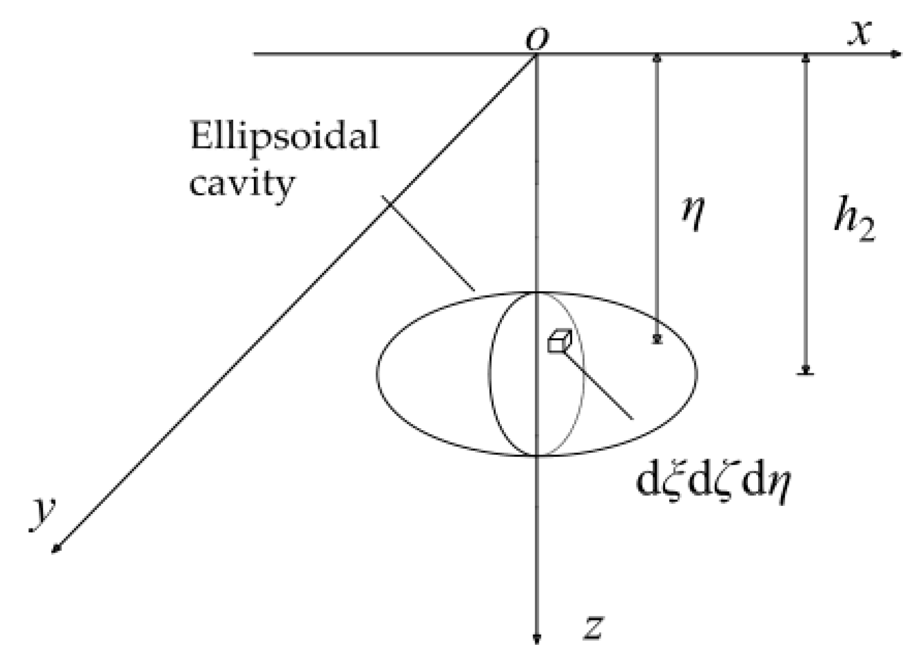
3.3.1. Introduction to Basic Theory

Taking an ellipsoidal cavity as an example, due to the influence of the tunnel excavation, its deformation mode is obviously related to the relative position of the tunnel. For example, a cavity located above the tunnel may have a combination of the vertical elliptical shrinkage and the overall settlement, while a cavity on the side of the tunnel may have a combination of the horizontal elliptical shrinkage and the horizontal overall displacement. Generally, the deformation characteristics of the cavity are largely reflected in the deformation of the geometric shape and the overall displacement. This work assumes that the cavity has been generated and maintains a stable structure before the tunnel excavation. The surface deformation and the soil deformation caused by the cavity before the tunnel excavation are not within the scope of this paper.
On the basis of the random medium theory and the research results of Qi et al. [9], the final settlement volume of the upper soil caused by the convergent deformation of the cavity should be equal to the lost volume of the soil.
In the cavity, for any calculation unit volume d ξ d ζ d η with a depth of burial of η, the displacement values of the soil at any point (x, y, z) in each direction, i.e., d U x , d U y , and d U z , caused by the complete collapse of the excavation unit are given by:
d U x = x r 3 ( z ) tan β exp [ π r 2 ( z ) ( x 2 + y 2 ) ] d ξ d ζ d η
d U y = y r 3 ( z ) tan β exp [ π r 2 ( z ) ( x 2 + y 2 ) ] d ξ d ζ d η
d U z = 1 r 2 ( z ) exp [ π r 2 ( z ) ( x 2 + y 2 ) ] d ξ d ζ d η
where β is the main influence angle of the upper part of the tunnel; d ξ , d ζ , and d η represent the integral units in the direction of the x-axis, y-axis, and z-axis respectively; r ( z ) is the influence radius in the z direction defined as
r ( z ) = η z tan β
On the basis of the above equations, Qi et al. [9] considered the variation of tan β with the depth of the excavation unit (h) and optimized parameter β as follows:
tan β z = h z 2 π i z
where iz is the width coefficient of the soil settlement trough defined as i z = i 0 ( 1 z h ) 0.3 [25]; i0 is the width coefficient of the ground settlement trough and can be calculated according to the methods of Knothe [26], Peck [27], or O’Reilly and News [28].
Knothe’s method defines it as
i 0 = h 2 π tan ( 45 φ 2 )
where φ is the friction angle of the soil.
Peck’s method expresses it in
i 0 = R s ( h 2 R s ) n
where Rs is the radius of the spherical cavity, and n ranges from 0.8 to 1.0.
In order to be consistent with ref [4], this paper chooses the method of O’Reilly and News, that is,
i 0 = K h
where K is the width parameter of the formation settlement trough.

3.3.2. Derivation of Calculation Formula

A symmetrical convergence deformation model of an ellipsoidal cavity is established as shown in Figure 3. Ra, Rb, and Rc represent the radius of the ellipsoidal cavity along the x-axis, y-axis, and z-axis respectively. d V = d ξ d ζ d η is the calculation unit with a depth of burial of η in the ellipsoidal cavity. Under the influence of the tunnel excavation, the cavity converges and shifts. As shown in Figure 4, assuming that the converged cavity is still elliptical, its radius along the x-axis, y-axis, and z-axis will be reduced to R a , R b , and R c respectively. Center point o1 of the cavity also moves to point o2; Δz and Δy indicate the vertical displacement and the horizontal displacement respectively.
According to the method described in Section 3.3.1, the calculation units are respectively integrated within the cavity range before and after the convergent deformation. Then, the calculation results of the two parts are subtracted to obtain the deformation of the surrounding soil caused by the cavity deformation. U x q , U y q , and U z q are the deformations along the x-axis, y-axis, and z-axis respectively and expressed in:
U x q = a q 1 b q 1 c q 1 d q 1 e q 1 f q 1 d U x a q 2 b q 2 c q 2 d q 2 e q 2 f q 2 d U x = a q 1 b q 1 c q 1 d q 1 e q 1 f q 1 ( x ξ ) tan 2 β z ( η z ) 3 exp { π tan 2 β z ( η z ) 2 [ ( x ξ ) 2 + ( y ζ ) 2 ] } d η d ζ d ξ a q 2 b q 2 c q 2 d q 2 e q 2 f q 2 ( x ξ ) tan 2 β z ( η z ) 3 exp { π tan 2 β z ( η z ) 2 [ ( x ξ ) 2 + ( y ζ ) 2 ] } d η d ζ d ξ
U y q = a q 1 b q 1 c q 1 d q 1 e q 1 f q 1 d U y a q 2 b q 2 c q 2 d q 2 e q 2 f q 2 d U y = a q 1 b q 1 c q 1 d q 1 e q 1 f q 1 ( y ζ ) tan 2 β z ( η z ) 3 exp { π tan 2 β z ( η z ) 2 [ ( x ξ ) 2 + ( y ζ ) 2 ] } d η d ζ d ξ a q 2 b q 2 c q 2 d q 2 e q 2 f q 2 ( y ζ ) tan 2 β z ( η z ) 3 exp { π tan 2 β z ( η z ) 2 [ ( x ξ ) 2 + ( y ζ ) 2 ] } d η d ζ d ξ
U z q = a q 1 b q 1 c q 1 d q 1 e q 1 f q 1 d U z a q 2 b q 2 c q 2 d q 2 e q 2 f q 2 d U z = a q 1 b q 1 c q 1 d q 1 e q 1 f q 1 tan 2 β z ( η z ) 2 exp { π tan 2 β z ( η z ) 2 [ ( x ξ ) 2 + ( y ζ ) 2 ] } d η d ζ d ξ a q 2 b q 2 c q 2 d q 2 e q 2 f q 2 tan 2 β z ( η z ) 2 exp { π tan 2 β z ( η z ) 2 [ ( x ξ ) 2 + ( y ζ ) 2 ] } d η d ζ d ξ
where letters a and b are the lower and upper limits of the integral of variable ξ along the x-axis respectively; letters c and d denote the lower and upper limits of the integral of variable ζ along the y-axis respectively; letters e and f indicate the lower and upper limits of the integral of variable η along the z-axis respectively; q1 and q2 represent the ellipsoidal cavity before and after the deformation respectively. The calculation formulas for the upper and lower limits of each integral are expressed by: a q 1 = R a , b q 1 = R a , c q 1 = R b 1 ξ 2 R a 2 , d q 1 = R b 1 ξ 2 R a 2 , e q 1 = h 1 R c 1 ξ 2 R a 2 ζ 2 R b 2 , f q 1 = h 1 + R c 1 ξ 2 R a 2 ζ 2 R b 2 , a q 2 = R a , b q 2 = R a , c q 2 = Δ y R b 1 ξ 2 R a 2 , d q 2 = Δ y + R b 1 ξ 2 R a 2 , e q 2 = h 1 + Δ z R c 1 ξ 2 R a 2 ζ 2 R b 2 , f q 2 = h 1 + Δ z + R c 1 ξ 2 R a 2 ζ 2 R b 2 .

3.3.3. Calculation of Convergence Rate of Cavity and Discussion of Convergence Modes

The above method can be used to calculate the surface settlement value caused by the shielded tunneling in the strata with cavities. The convergence rate of the cavity and the radii of the converged cavity ( R a , R b , R c ) should be determined by the following method.
First, the cavity is a hidden one, and its convergence rate is difficult to measure in actual engineering. This paper refers to the research results of Loganathan [22] and believes that the convergence rate of the cavity can be estimated based on its relative position to the tunnel and the loss rate of the soil during the tunnel excavation as follows:
ε s = η s exp { [ 1.38 y s 2 ( H + R ) 2 + 0.69 z s 2 H 2 ] }
where (ys, zs) is the coordinate of the center point of the cavity.
Although this work assumes that the cavity is ellipsoidal before and after the convergence, in actual engineering, the deformation mechanism of the cavity is more complex, and irregular deformation may occur. From the perspective of theoretical calculations, this paper should develop a model suitable for the calculation of the soil deformation caused by the cavities in different locations. From the previous analysis, we can conclude that the ellipsoidal cavity has the stablest stress state during the long-term formation process, which is also the commonest. Since the convergence rate of the cavity can be calculated by Equation (18), irrespective of the type of the irregular deformation of the cavity at a certain location, the convergence rate of the cavity basically remains unchanged.
After analysis, this paper divides the deformation of the cavity into three modes, namely the uniform deformation, the horizontal elliptical deformation, and the vertical elliptical deformation, of which the horizontal elliptical deformation and the vertical elliptical deformation are two extreme states.
As illustrated in Figure 5, in the uniform convergence mode, the ellipsoidal cavity is reduced in the same proportions on the x-axis, y-axis, and z-axis; moreover, the radial reductions ga, gb, and gc respectively in the directions of the x-axis, y-axis, and z-axis satisfy the following relationship:
g a = 2 R a ( 1 1 ε s )
g b = 2 R b ( 1 1 ε s )
g c = 2 R c ( 1 1 ε s )
On the basis of Equations (19)–(21), the three radii of the converged ellipsoidal cavity ( R a , R b , and R c ) can be calculated by:
{ R a = R a g a R b = R b g b R c = R c g c
As shown in Figure 6, it is assumed that the convergent value in the directions of the x-axis and y-axis is zero when the cavity is horizontally elliptical, and all the convergence occurs in the z direction. The radius of the cavity converged in the z direction satisfies:
ε s = π R b R c π R b R c π R b R c
Thus, R a , R b , and R c are given by:
{ R a = R a R b = R b R c = R c ( 1 ε s )
As shown in Figure 7, assuming that the variation in the radius of the cavity in the x direction is similar to that in the y direction in the state of the vertical elliptical convergence, the converged radii of the cavity in the directions of the x-axis and y-axis are equal, that is R a = R b , and both satisfy:
ε s = π R a R b π R a R b π R a R b
Thus, R a , R b , and R c are expressed by:
{ R a = R a ( 1 ε s ) R b = R b ( 1 ε s ) R c = R c
Three cavity symmetry convergence modes are proposed above, and the radii R a , R b , and R c of the converged ellipsoidal cavity can be calculated according to the convergence rate of the cavity. By substituting these radii ( R a , R b , and R c ) into Equations (15)–(17), the deformations of the surrounding soil along the x-axis, y-axis, and z-axis ( U x q , U y q , and U z q ) caused by the convergent deformation of the cavity are obtained.

3.4. Calculation of Total Displacement of Ground with Cavity under Influence of Shielded Tunneling

By combining the calculation results in Section 3.2 and Section 3.3 and superimposing the soil deformation caused by the tunnel and the cavity, the final deformation of the soil in the directions of the y-axis and z-axis (Uy and Uz) at any position above the cavity and the tunnel can be defined as:
U y = U y s + U y q
U z = U z s + U z q

4. Instance Verification

4.1. Case Introduction

This work uses the experimental case introduced in ref. [4] as the engineering background and compares the obtained theoretical results with the experimental data to verify the reliability of the developed calculation method. This experimental case uses a total of four sets of working conditions to study the influence of a spherical cavity at different positions on the ground settlement caused by the tunnel excavation. As shown in Figure 8, no cavity is considered in case 1, the cavity in case 2 is located above the tunnel, the cavity in case 3 is situated diagonally opposite the tunnel on its right side, and the cavity in case 4 is located parallel to the tunnel on its right side. Moreover, in the experiment, the formation cavity was simulated by a spherical balloon with a diameter of 14 cm. The tunnel excavation process was also simulated by unloading eight cylindrical balloons with a diameter of 200 mm step by step. In actual working conditions and experiments, the similarity ratio of the size to the displacement and equipment is 30:1. In this paper, the experimental data are first converted into actual engineering data for analysis and verification. The diameter of the tunnel is set at 6 m, and the depth of burial of the cavity (H) is 15 m; the diameter of the spherical cavity is equal to 4.2 m, and the clear distance between the tunnel and the spherical cavity is 3 m; the depth of the center of the spherical buried cavities in working conditions 2, 3, and 4 is 6.9, 9.27, 15 m respectively. The tunnel excavation is carried out in eight steps, and the length of each excavation is 6 m. Taking the center of the cavity as the zero point, the excavation ranges from –15 m to 27 m, and K = 0.736.
Ref. [4] only provides the total loss rate of the stratum, i.e., the sum of the loss rates of the tunnels and the cavities, under conditions 1–4 equal to 3.26%, 5.73%, 7.91%, and 7.91% respectively. In this paper, ηs and εs can be calculated under various working conditions according to the definition formula for the soil loss and Equation (10). There is no cavity under working condition 1, and the total loss rate of the stratum is equal to the loss rate of the tunnel soil, that is, ηs = 3.26%. In case 2, the cavity coordinates (ys, zs) are (0 m, 6.9 m), and the corresponding ηs and εs can be calculated at 5.592% and 4.831% respectively. In case 3, the cavity coordinates (ys, zs) are (5.73 m, 9.27 m), and the corresponding ηs and εs can be calculated at 7.762% and 5.185% respectively. In case 4, the cavity coordinates (ys, zs) are (8.1 m, 15 m), and the corresponding ηs and εs can be calculated at 7.825% and 2.966% respectively. The values of d under working conditions 1–4 are 0.8R, 0.1R, 0.1R, and 0.1R respectively.

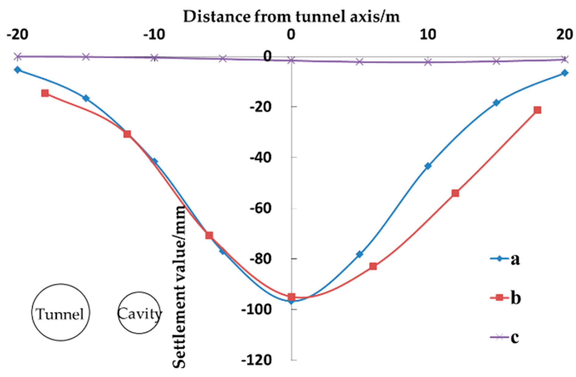
4.2. Comparison of Results in Different Convergence Deformation Modes

According to the above calculation method, under the influence of the tunnel excavation, the surface settlement curves formed when the cavity undergoes the uniform shrinkage deformation, the horizontal elliptical deformation, and the vertical elliptical deformation can be calculated. Figure 9 compares the corresponding ground settlement values of the cavity in the three convergence modes. It is obvious that the surface settlement curves obtained in the three convergence modes are roughly in agreement, all of which are normally distributed and symmetrically distributed along the tunnel axis. The maximum settlement values of the center are 91.27, 86.51, and 84.82 mm in the three modes of the uniform deformation, the horizontal elliptical deformation, and the vertical elliptical deformation, respectively. The maximum settlement in the center of the ground surface calculated in the uniform convergence mode is slightly larger than that in the modes of the horizontal elliptical deformation and the vertical elliptical deformation by 4.76 and 6.45 mm respectively. However, the two modes of the elliptical deformation are both the extreme states. Even if the actual elliptical cavity deformation occurs, it is a state between the uniform shrinkage deformation and the corresponding extreme state. In other words, the maximum settlement in the center of the ground surface is between 86.51 and 91.27 mm (the horizontal elliptical deformation) or 84.82 to 91.27 mm (the vertical elliptical deformation). The difference between the actual calculated value and the value determined in the mode of the uniform convergence deformation is smaller, so it is more reasonable to use the mode of the uniform convergence deformation, which can also fulfill the accuracy requirements, to calculate the ground settlement.
Through the discussion of each extreme state of the elliptical deformation of the cavity, it can be proved that the uniform symmetrical convergence model is more accurate about the calculation of the surface settlement. It can solve the problem when the shape of the cavity is complex and difficult to be calculated directly because the cavity is disturbed by the tunnel excavation. Therefore, when calculating the displacement of the upper soil caused by the cavity deformation, adopting the uniform symmetrical convergence mode is recommended. Therefore, the subsequent studies in this paper employ the uniform symmetrical convergence mode for the calculations and analyses.

4.3. Calculation Results and Reliability Verification of Devised Method

The experimental data in ref [4] are converted and compared with the theoretical calculation results to verify the reliability of the method developed herein. Referring to the model diagram in Figure 2, the selected tunnel excavation section is located at x = 27 m, the center of the spherical cavity is located on the z-axis, and the research section is directly above the center of the cavity.
Figure 10 delineates the distribution of the surface settlement caused by the tunnel excavation in the stratum without cavity under condition 1. It can be seen that our calculation results are in good agreement with the experimental data reported by Cai et al. [4]. The calculated surface settlement curve is a normal distribution, and the settlement influence ranges from −20 m to 20 m; the maximum settlement occurs in the center of the tunnel excavation and equals 56.93 mm. Moreover, the maximum settlement value reported in the experimental work of Cai et al. [4] is 56.37 mm which differs from our result by only −0.56 mm; thus, the method developed herein satisfies the accuracy requirements.
Figure 11 shows the distribution of the ground settlement caused by the tunnel excavation when the cavity is located directly above the tunnel under condition 2. After the calculations, under working condition 2 (ηs = 5.592% and εs = 4.831%), the vertical displacement of the cavity is 86.3 mm, and its horizontal displacement is zero. Compared with condition 1, the displacement and convergence of the cavity can affect the soil loss rate of the tunnel. It is clear that the theoretical calculation results are consistent with the experimental curves. The existence of the cavity directly above the tunnel makes the central surface settlement increase significantly from 56.93 to 91.27 mm. The settlement influence range is basically unchanged (from –20 m to 20 m), and the settlement curve is symmetrical about the center. The difference between the experimental maximum settlement value (91.05 mm) and the theoretically calculated one is only 0.22 mm, which indicates that the devised method fulfills the accuracy requirements. In addition, the largest surface settlement caused by the cavity alone occurs in the center of the cavity and equals 23.41 mm which accounts for 25.65% of the total settlement, while the proportion of the surface settlement caused by the tunnel excavation is 74.35%.
Figure 12 shows the distribution of the ground settlement caused by the tunnel excavation when the cavity is located diagonally opposite the tunnel on its right side under condition 3. After the calculations, under working condition 3 (ηs = 7.762% and εs = 5.185%), the vertical displacement of the cavity is 70 mm, and its horizontal displacement is equal to –37.3 mm. Compared with condition 2, due to the deviation of the cavity from the center of the tunnel excavation under condition 3, the overall surface settlement curve also shifts slightly to the deviation direction of the cavity, and the settlement value on one side of the cavity is slightly larger than that on the other side of it, gradually showing asymmetry. It can be seen in the figure that the theoretical calculation results are similar to the experimental data. The theoretically calculated maximum settlement value occurs at y = 0.4 m and is about 101.63 mm. Furthermore, the maximum surface settlement caused by the cavity alone is located in the center of the cavity. The settlement values at y = 0 m and y = 5 m are 7.51 and 12.09 mm respectively, accounting for 7.38% and 13.82% of their respective total settlement values. The experimental results show that the maximum settlement value occurs at y = 2.5 m and is about 101.33 mm. In summary, although the experimental overall settlement curve slightly shifts to the right, the theoretical calculation results are still in good agreement with the experimental data, which implies that the method developed in this paper satisfies the accuracy requirements.
Figure 13 shows the comparison of the surface settlement curves under condition 4. After the calculations, under working condition 4 (ηs = 7.825% and εs = 2.966%), the vertical displacement of the cavity is 14.6 mm, and its horizontal displacement equals –28.6 mm. It is obvious that the theoretically calculated maximum settlement value is 93.62 mm and occurs at y = 0 m. The maximum value of the experimental curve is 94.89 mm and occurs at y = 0.81 m. As the depth of burial of the cavity increases, the surface settlement caused by the cavity significantly declines, and its impact on the total surface settlement is relatively small. Compared with condition 3, the degree of the deviation of the settlement curve toward the direction of the cavity is reduced under condition 4, which is attributed to the fact that the soil deformation caused by the cavity itself is smaller than that caused by the tunnel excavation. When the cavity deviates from the tunnel by more than a certain distance, the position of the maximum overall surface settlement is not affected or is slightly affected, and it still occurs roughly near the surface corresponding to the tunnel excavation. However, due to the effect of the cavity, the soil settlement on the right side of the tunnel is larger than that on the left side of it. Comparing the theoretical calculation curve with the experimental one reveals a certain difference between the two on the right side of the curve; indeed, the theoretically calculated settlement value is smaller than the experimental one. Nonetheless, the curves on the left are in good agreement.
On the whole, the theoretical results calculated in this work are basically consistent with the data reported by Cai et al. [4]. Moreover, when the cavity is located directly above the tunnel, the accuracy of the theoretically calculated results is higher, which verifies the reliability of the method developed herein.
In actual engineering applications, when the shielded tunneling parameters, the soil parameters, and the relative position of the tunnel and the cavity are known, the developed calculation method can be utilized to determine the convergence rate and displacement of the cavity caused by the shielded tunneling, based on which the surface settlement caused by the cavity alone can be calculated; then, the total surface settlement can be determined by adding up the surface settlement caused by the shielded tunneling. The devised method can analyze the characteristics of the surface settlement caused by shielded tunneling in the strata with cavities. If the surface settlement is too large, the shielded tunneling plan can be adjusted, or some other safety control measures can be taken to reduce the surface settlement. Therefore, it can have a certain significance for guiding the actual engineering design.

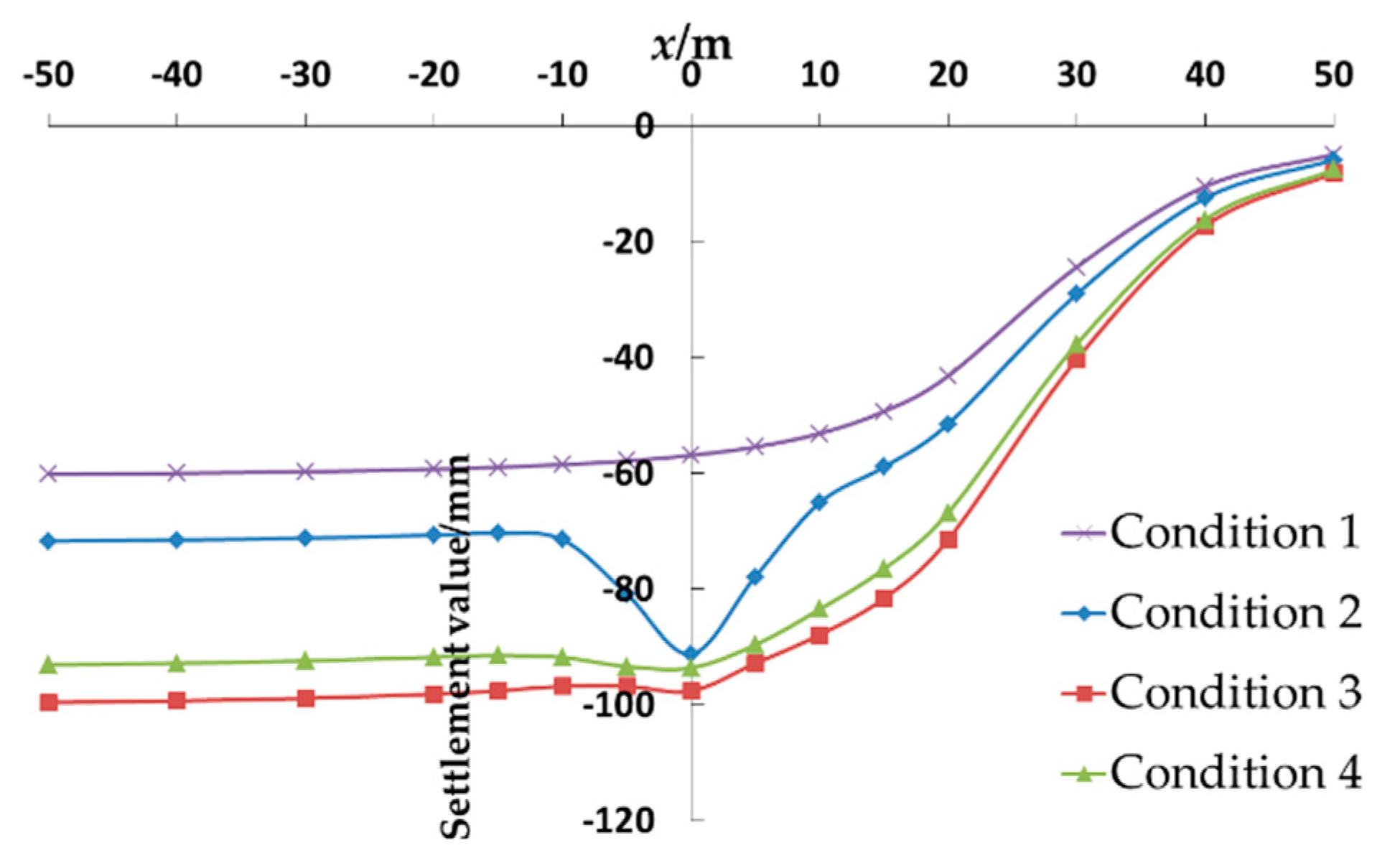
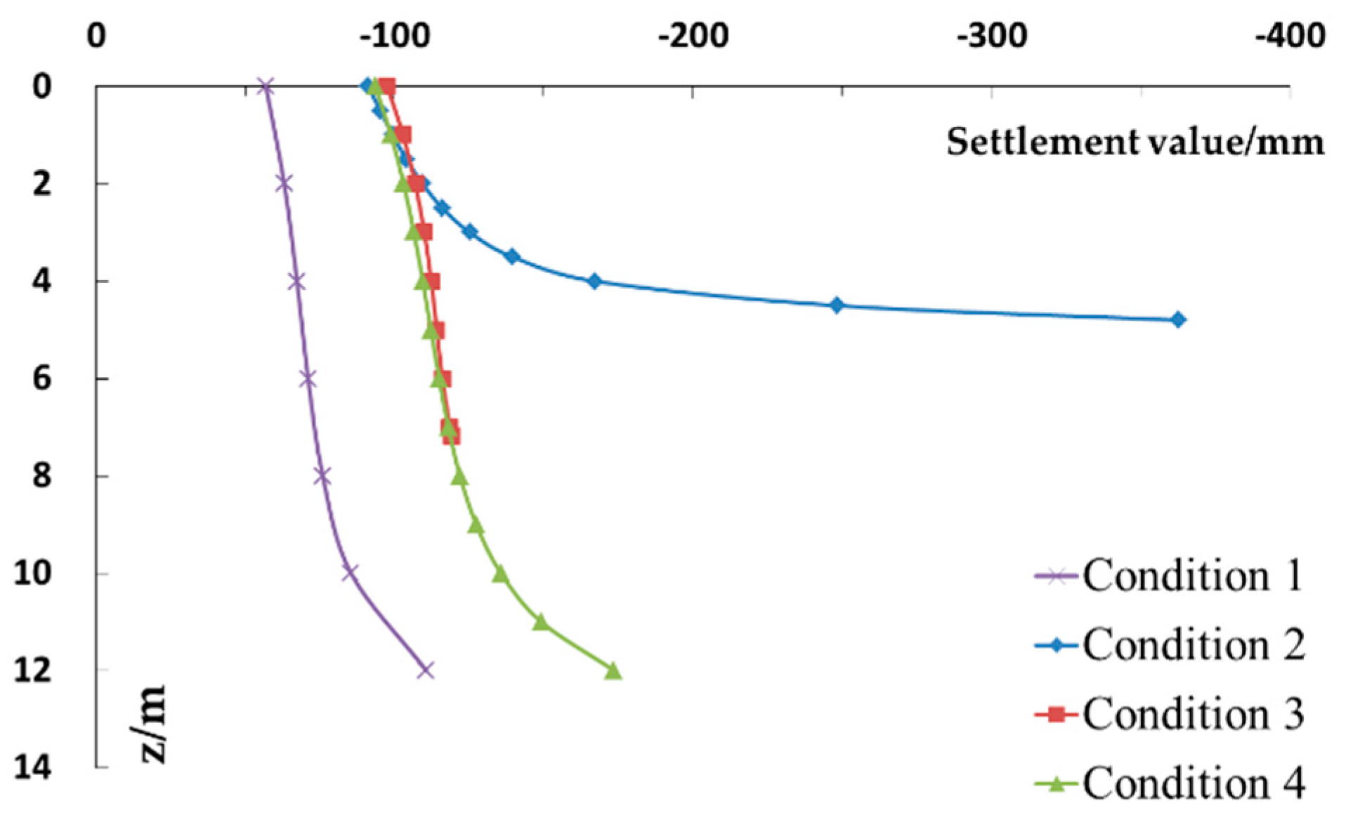
4.4. Distribution Law of Vertical Displacement of Soil along x-Axis and z-Axis

Assuming that the surface of the tunnel excavation is located at x = 27 m, the distribution and change law of the vertical displacement of the soil along the x-axis and z-axis under conditions 1, 2, 3, and 4 are examined.
Figure 14 delineates the distribution of the vertical settlement along the x-axis. First, the trend of the variation in the surface settlement is similar under each working condition, and all the surface settlement values decrease with an increase in x. When x declines to –20 m, the surface settlement basically tends to be stable, and when x approaches infinity, the surface settlement gradually approaches zero. Second, the x-coordinate of the center of the cavity under conditions 2, 3, and 4 are all equal to zero. Under condition 2, it is obvious that the surface settlement curve has a partial downward protrusion within the range of −10 m to 10 m; thus, a significant increase in the soil settlement is caused by the cavity. Third, the soil settlement curves under conditions 3 and 4 have a much lower degree of convexity compared to that under condition 2. The main reason for this is that the y-coordinate of the center of the cavity under conditions 3 and 4 is 5.73 and 8.1 m respectively which are far away from the x-axis. Thus, the deformation of the cavity has a limited range of influence, so the variation in the vertical settlement of the soil along the x-axis is negligible.
Figure 15 plots the variation in the vertical settlement of the soil along the z-axis. Since the depth of burial of the cavity is different under each condition, only the soil above the cavity and the tunnel is studied herein, that is, the depth of burial of the cavity is set at 12, 4.8, 7.17, and 12 m under conditions 1, 2, 3, and 4 respectively. It can be seen in Figure 15 that the settlement of the soil enlarges with an increase in z, and the curve of the settlement near the surface grows more slowly. When it gradually approaches the upper part of the cavity or the tunnel, its growth rate continues to rise until it finally reaches a maximum. Further, the maximum soil settlement under condition 1 equals 110.65 mm and occurs at z = 12 m, that is, the position of the upper end of the tunnel. The maximum soil settlement under condition 2 is equal to 362.69 mm and occurs at z = 4.8 m, which is the position of the upper end of the cavity. The maximum soil settlement under condition 3 is 119.18 mm and occurs at z = 7.17 m, which is equal to the depth of the upper end of the cavity. The maximum soil settlement under condition 4 is equal to 173.56 mm and occurs at z = 12 m, which is the upper end of the tunnel.

5. Conclusions

The following conclusions can be drawn from the findings of the current work:
First, the existence of stratum cavities aggravates the surface settlement and deformation of shallow soil. When the cavity deviates from the tunnel axis within a certain range, the surface settlement curve moves slightly to the direction of the cavity offset, and gradually changes from symmetrical distribution to asymmetrical distribution. Compared with the tunnel excavation, the cavity has a smaller impact on the ground settlement, and its influence range is limited. Hence, when the cavity deviates far from the tunnel, its impact on the soil settlement gradually weakens. Nevertheless, the ground settlement is still greater on the one side of the cavity than on the other side of it.
Second, the surface settlement value decreases with an increase in x; indeed, when x approaches infinity, the surface settlement value approaches zero. When x declines to −20 m, the surface settlement value approaches a stable maximum. The existence of the cavity aggravates the surface settlement within the range of −10 m to 10 m, and its impact is gradually reduced as its distance from the tunnel increases. Along the z-axis, the deformation of the soil above the tunnel and the cavity enlarges with an increase in the depth of burial of the cavity. Moreover, the growth rate of the soil settlement near the surface is relatively gentle but rises at positions closer to the cavity or above the tunnel.
Third, in actual engineering, new tunnels should try to avoid traversing the stratum containing voids. At the same time, it is necessary to pay attention to the most dangerous to cross directly under the void, which can easily lead to large soil deformation and surface settlement above the void. It is recommended to grouting and filling the cavity in advance before the excavation of the new tunnel.
Fourth, this work assumes that the cavity undergoes the uniform convergent deformation, which is considered to be a certain simplification. Further studies should be conducted on the variation law of the shape of the cavities at different locations so as to summarize a set of calculation methods for soil displacement suitable for the real deformation of cavities. In addition, this article only considers the impact of tunnel excavation on the cavity. This article assumes that the cavity only changes in shape and position, but does not collapse.

Author Contributions

Conceptualization, Y.Q.; methodology, Y.Q.; software, Y.Q. and Z.D.; validation, Y.Q., G.W., Y.C. and Z.D.; data curation, Y.Q.; writing—original draft preparation, Y.Q.; writing—original draft preparation, Y.Q., G.W., Y.C. and Z.D. All authors have read and agreed to the published version of the manuscript.

Funding

This research was supported by National Natural Science Foundation of China Youth Project, grant number 51808493.

Institutional Review Board Statement

Not applicable.

Informed Consent Statement

Not applicable.

Data Availability Statement

The data used to support the findings of this study are included in the article.

Acknowledgments

We are grateful to the other members of our research team (ZHANG, S.M. and ZHAO, D.Q.L.) for their technical support.

Conflicts of Interest

The authors declare no conflict of interest.

References

  1. Fang, Q.; Zhang, D.; Wang, L. Environmental risk management for a cross interchange subway station construction in China. Tunn. Undergr. Space Technol. 2011, 26, 750–763. [Google Scholar] [CrossRef]
  2. Meguid, M.A.; Dang, H.K. The effect of erosion voids on existing tunnel linings. Tunn. Undergr. Space Technol. 2009, 24, 278–286. [Google Scholar] [CrossRef]
  3. Leung, C.; Meguid, M.A. An experimental study of the effect of local contact loss on the earth pressure distribution on existing tunnel linings. Tunn. Undergr. Space Technol. 2011, 26, 139–145. [Google Scholar] [CrossRef]
  4. Cai, Y.; Zhang, C.P.; Min, B. Deformation characteristics of ground with voids induced by shallow metro tunneling. Chin. J. Geotech. Eng. 2019, 41, 534–543. [Google Scholar]
  5. Islam, R.; Jalali, J.S.; Vaziri, H.H. An analytical model for stability analysis of rock layers over a circular opening. Int. J. Solids Struct. 2001, 38, 3735–3757. [Google Scholar]
  6. Augarde, C.E.; Lyamin, A.V.; Sloan, S.W. Prediction of undrained sinkhole collapse. J. Geotech. Geoenviron. Eng. 2003, 129, 197–205. [Google Scholar] [CrossRef] [Green Version]
  7. Zhang, C.-P.; Zhang, D.L.; Wang, M.S.; Li, Q.Q.; Liu, S.C. Catastrophe mechanism and control technology of ground collapse induced by urban tunneling. Rock Soil Mech. 2010, 31, 303–309. [Google Scholar]
  8. Zhang, Y.; Zhang, C.P.; Li, Q.Q.; Zheng, L.; Yi, C. Influence of Cavity above Tunnel on Stratum Deformation and Failure in Urban Tunneling. Appl. Mech. Mater. 2012, 170, 1810–1815. [Google Scholar] [CrossRef]
  9. Li, Q.Q.; Zhang, D.L.; Fang, Q. Analytic solution to initial damage of cavern strata by complex function method. Chin. J. Geotech. Eng. 2014, 36, 2110–2117. [Google Scholar]
  10. Yang, G.B.; Zhang, C.P.; Min, B.; Cai, Y. Elastic solution of soil displacement induced by shallow circular tunnel with a cavern in a stratum using function of complex variable method. Rock Soil Mech. 2018, 39, 25–36. [Google Scholar]
  11. Yang, X.L.; Wang, J.M. Ground movement prediction for tunnels using simplified procedure. Tunn. Undergr. Space Technol. 2011, 26, 462–471. [Google Scholar] [CrossRef]
  12. Park, K.H. Elastic Solution for Tunneling-Induced Ground Movements in Clays. Int. J. Geomech. 2004, 4, 310–318. [Google Scholar] [CrossRef]
  13. Golpa, S.N.M.; Do, N.A.; Dias, D. Impact of pre-existent Qanats on ground settlements due to mechanized tunneling. Transp. Geotech. 2019, 21, 100262. [Google Scholar]
  14. Yao, Q.; Di, H.; Ji, C. Ground collapse caused by shield tunneling in sandy cobble stratum and its control measures. Bull. Eng. Geol. Environ. 2020, 79, 5599–5614. [Google Scholar] [CrossRef]
  15. Wang, Z.; Qu, T.; Li, B. Analysis of Stratigraphic Subsidence Caused by Sand Leakage in Tunnel Lining. Geotech. Geol. Eng. 2020, 39, 2029–2039. [Google Scholar] [CrossRef]
  16. Hu, X.; Jiang, X.; Li, K.; Cui, X. Research on Tunnel Lining Cavity Treatment Technology of a Metro Tunnel in Chongqing. In IOP Conference Series Earth and Environmental Science; IOP Publishing: Bristol, UK, 2019. [Google Scholar]
  17. Fazio, N.L.; Lollino, P.; Perrotti, M.; Parise, M.; Vattano, M.; Madonia, G.; Di Maggio, C. A three-dimensional back-analysis of the collapse of an underground cavity in soft rocks. Eng. Geol. 2016, 228, 301–311. [Google Scholar] [CrossRef]
  18. Qi, J.J.; Xu, R.Q.; Wei, G. Research on calculation method of soil 3D displacement due to shield tunnel construction. Rock Soil Mech. 2009, 30, 2442–2446. [Google Scholar]
  19. Wei, G. 3-D Analytical Solution of Ground Deformation Induced by Shield Tunneling Construction. Available online: https://www.researchgate.net/publication/290288412_Prediction_of_ground_deformation_induced_by_shield_tunneling_construction (accessed on 1 March 2021).
  20. Sun, S.; He, P.; Wang, G.; Li, W.; Wang, H.; Chen, D.; Xu, F. Shape characterization methods of irregular cavity using Fourier analysis in tunnel. Math. Comput. Simul. 2021, 187, 191–214. [Google Scholar] [CrossRef]
  21. Tian, S. Deformations and Progressive Failure Laws of the Ground with Voids Influenced by Shallow Tunneling. Master’s Thesis, Beijing Jiaotong University, Beijing, China, 2016. [Google Scholar]
  22. Loganathan, N.; Poulos, H.G. Analytical prediction for tunneling-induced ground movement in clays. J. Geotech. Geoenviron. Eng. 1998, 124, 846–856. [Google Scholar] [CrossRef]
  23. Verruijt, A.; Booker, J.R. Surface settlements due to deformation of a tunnel in an elastic half plane. Geotechnique 1996, 46, 753–756. [Google Scholar] [CrossRef]
  24. Wei, G. Prediction of ground deformation induced by shield tunneling construction. Chin. J. Rock Mech. Eng. 2009, 28, 418–424. [Google Scholar]
  25. Jiang, X.L.; Zhao, Z.M.; Li, Y. Analysis and calculation of surface and subsurface settlement trough profiles due to tunneling. Rock Soil Mech. 2004, 25, 1542–1544. [Google Scholar]
  26. Knothe, S. Observations of surface movements under influence of mining and their theoretical interpretation. In Proceedings of the European Congress on Ground Movement, Leeds, UK, 9–12 April 1957. [Google Scholar]
  27. Peck, R.B. Deep excavations and tunneling in soft ground. In Proceedings of the 7th International Conference on Soil Mechanics and Foundation Engineering, Mexico City, Mexico, 1969; Sociedad Mexicana de Mecanica: Mexico City, Mexico, 1969. [Google Scholar]
  28. O’Reilly, M.P.; New, B.M. Settlements above tunnels in the United Kingdom their magnitude and prediction. In Proceedings of the Tunneling’ 82 Symposium, Brighton, UK, 7–11 June 1982. [Google Scholar]
Figure 1. The flow chart of the method proposed herein.
Symmetry 13 01048 g001
Figure 2. The diagram of the calculation model: (a) the three-dimensional map; (b) the front view.
Symmetry 13 01048 g002
Figure 3. The convergent deformation model of an ellipsoidal cavity.
Symmetry 13 01048 g003
Figure 4. The diagram of the model considering the cavity convergence and the overall displacement.
Symmetry 13 01048 g004
Figure 5. The uniform symmetrical convergence mode of the cavity.
Symmetry 13 01048 g005
Figure 6. The horizontal elliptical symmetrical deformation mode of the cavity.
Symmetry 13 01048 g006
Figure 7. The vertical elliptical deformation mode of the cavity.
Symmetry 13 01048 g007
Figure 8. A schematic diagram of the relative positions of the cavity and the tunnel.
Symmetry 13 01048 g008
Figure 9. The comparison of the surface settlement in various convergence modes.
Symmetry 13 01048 g009
Figure 10. The comparison of the surface settlement curves under condition 1.
Symmetry 13 01048 g010
Figure 11. The comparison of the surface settlement curves under condition 2: (a) the results calculated in this paper; (b) the experimental results of Cai Yi et al. [4]; (c) the surface settlement caused by the cavity alone.
Symmetry 13 01048 g011
Figure 12. The comparison of the surface settlement curves under condition 3: (a) the results calculated in this paper; (b) the experimental results of Cai Yi et al. [4]; (c) the surface settlement caused by the cavity alone.
Symmetry 13 01048 g012
Figure 13. The comparison of the surface settlement curves under condition 4: (a) the results calculated in this paper; (b) the experimental results of Cai Yi et al. [4]; (c) the surface settlement caused by the cavity alone.
Symmetry 13 01048 g013
Figure 14. The variation in the vertical settlement of the soil along the x-axis.
Symmetry 13 01048 g014
Figure 15. The variation in the vertical settlement of the soil along the z-axis.
Symmetry 13 01048 g015
Publisher’s Note: MDPI stays neutral with regard to jurisdictional claims in published maps and institutional affiliations.

