Article

Wire Tension Coordination Control of Electro-Hydraulic Servo Driven Double-Rope Winding Hoisting Systems Using a Hybrid Controller Combining the Flatness-Based Control and a Disturbance Observer

1
School of Mechatronic Engineering, China University of Mining and Technology, Xuzhou 221116, China
2
Jiangsu Key Laboratory of Mine Mechanical and Electrical Equipment, China University of Mining and Technology, Xuzhou 221116, China
*
Author to whom correspondence should be addressed.
Symmetry 2021, 13(4), 716; https://doi.org/10.3390/sym13040716
Submission received: 18 February 2021 / Revised: 28 March 2021 / Accepted: 29 March 2021 / Published: 19 April 2021

Abstract

:
When the double-rope winding hoisting system (DWHS) is in operation, tensions of two wire ropes of the DWHS will not be symmetrical because of some factors such as different manufacturing deviation between the twin winding drum and two wire ropes, different winding groove depths, the winding asynchronism of two wire ropes, and elastic modulus difference of two wire ropes and so on. Therefore, an electro-hydraulic servo system (EHSS) is employed to actively control two wire ropes tensions to guarantee operation security of the DWHS. Dynamic models of the hoisting system and the EHSS are introduced, of which dynamic model of the DWHS is expressed with state representation. The flatness-based controller (FBC) is designed for the hoisting system. A disturbance observer is utilized to deal with the external disturbance and unmodeled characteristics of the EHSS. Hence, a disturbance observer based integral backstepping controller (DO-BIBC) is designed for the EHSS. The stability of the overall control system is proved by de-fining an overall Lyapunov function. To investigate the property of the proposed controller, an experimental setup of the DWHS is established. As well, comparative experimental results indicate that the proposed controller exhibits a better performance on leveling control of the conveyance and tension coordination control on the two wire ropes than a conventional PI controller.

1. Introduction

Blair hoists are proposed to realize the ultra-deep hoisting and have been employed in South Africa [1,2]. Based on Blair hoists, this paper presents a double-rope winding hoisting system (DWHS) in Figure 1. However, during the operation of the DWHS, some inevitable factors like different manufacturing deviation between the twin winding drum, the winding asynchronism of two wire ropes, difference in lengths between two wire ropes, different depths of winding grooves and elastic modulus difference of two wire ropes will result in different terminal displacements of two wire ropes. Under the restraint of guides, tensions of two wire ropes will be inevitably different. What’s more, when the conveyance is hoisted or lowered by one of two wire ropes, then the tension of the corresponding wire rope will be so big that causing wire rope broken accident. Since a hoisting system is the throat of a coal mine, it is fatally important to guarantee the safety of the hoisting system. Therefore, coordinating the tension difference is imperative.
As shown in Figure 1, two conveyances are hoisted or lowered by a twin winding drum. In order to adjust the tension difference actively and quickly, a tension coordination system, which is composed of two movable headgear sheaves, two active hydraulic cylinders, many kinds of indispensable sensors, and mechanical structures, is employed and the tension difference can be coordinated by two active hydraulic cylinders drive two movable headgear sheaves. Consequently, the DWHS is composed of a hoisting system and an electro-hydraulic servo system (EHSS).
A conventional proportional-integral (PI) controller, which is easy to design and almost universal in any a control system, can certainly reduce the tension difference between the two wire ropes [3,4]. However, since the DWHS has many nonlinearities like geometric nonlinearities of flexible wire ropes, structure vibrations of the DWHS, disturbances of the DWHS and parameter uncertainties of the EHSS, the performance of the PI controller is unsatisfactory. The feedback linearization technology utilizes the system states feedbacks to linearize nonlinear behaviors of a system and then improves the tension coordination [5,6,7]. Based on the state representation of the DWHS, many controllers like sliding mode controllers [1,8,9,10,11], robust controllers [12,13,14,15], adaptive controllers [16,17], iterative leaning controllers [18] are designed to coordinate the tension difference. Backstepping controllers divide the model of a system into several subsystems, then design the corresponding virtual control law by defining proper Lyapunov function, and the real control law of the overall system is obtained in the final step [19,20]. Backstepping controllers exhibit better performances than the above controllers [3,21,22,23]. Recently, the flatness-based controller (FBC) draws a wide concern of scholars and it is superior to the backstepping control in the control design complication and the efficiency, which has been proved by many scholars [24,25,26,27,28,29], the control method is able to provide desirable output characteristics and robustness against unmodeled dynamics and unknown inputs [30]. However, there always are disturbances when the DWHS including the hoisting system and the EHSS is in an operation. Since the FBC can’t directly compensate for external disturbances, the integrator of the angle tracking error of the hoisting system and the position tracking error of the EHSS can compensate the steady-state error resulted by the constant disturbance [25,31]. As we all know, stochastic disturbances from the load force affect the operation of the EHSS seriously. A disturbance observer is an effective method to deal with the stochastic disturbance and unmodeled characteristics of a system [32,33] and disturbance compensation is crucial for realizing high-precision servo control [34]. By properly choosing the desired function to be designed and the control gain of the observer can guarantee its stability. The high gain disturbance observer [35,36] and the low gain disturbance observer [37] are both have been proved their efficiency in compensating external disturbances. Hence, the observer can be employed to compensate the stochastic disturbance in the backstepping controller design.
Therefore, in this paper, we propose a hybrid controller combining the FBC and a disturbance observer based integral backstepping controller (DOBIBC) to balance the two wire rope tensions efficiently to guarantee the safety of the DWHS. The hybrid controller can compensate disturbances including the constant disturbance and the stochastic disturbance of the DWHS and the unmodeled characteristics of the EHSS to reduce its tension difference. What’s more, comparative experimental results illustrate that the hybrid controller shows better performance that the conventional PI controller.
This work can be organized as follows. The dynamic model of the DWHS is shown in Section 2. The design process of hybrid controller for the DWHS is presented in Section 3. Section 4 shows the experimental setup and comparative results. The conclusion is summarized in Section 5.

2. Dynamic Model of the DWHS

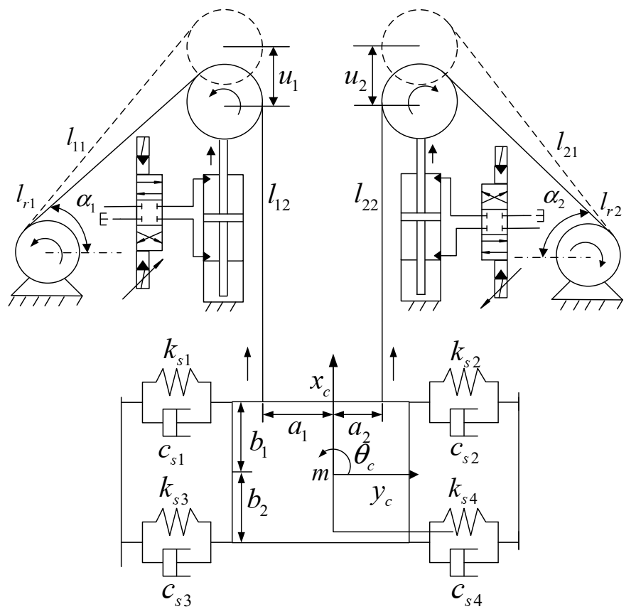
Figure 2 exhibits the operating principle of the DWHS, in which a twin-drum winds two wire ropes to hoist a conveyance with flexible shaft guided. As can be seen from the detail view part of Figure 1, the two headgear sheaves are floating and can make vertical motions for two wire rope tensions balance. As shown in references [13,29], the DWHS can be modelled as follows, and Appendix A presents the nomenclature of the model.
In order to realize the leveling control of the conveyance, the two wire ropes differ in length need to be adjusted with the help of motion of two hydraulic cylinders. To simplify the control input, the control input is made as u 1 = u = u 2 . Moreover, the anticlockwise rotation angle θ c is regarded as controlled object, then the nonlinear dynamical model of hoisting system can be represented as
A θ ¨ c + B θ ˙ c + C θ c = R u + F 0
where,
{ A = I c 1 3 ρ l h 1 a 1 2 + 1 3 ρ l h 2 a 2 2 B = ( c h 1 + 1 3 ρ l ˙ h 1 ) a 1 2 + ( c h 2 + 1 3 ρ l ˙ h 2 ) a 2 2 + b 1 2 c s 1 + b 2 2 c s 2 + b 1 2 c s 3 + b 2 2 c s 4 C = k h 1 a 1 2 + k s 2 a 2 2 + k s 1 b 1 2 + k s 2 b 2 2 + k s 3 b 1 2 + k s 4 b 2 2 Q = 1 6 ρ l h 1 a 1 ( 1 + sin ( φ 1 ) ) + 1 6 ρ l h 2 a 2 ( 1 + sin ( φ 2 ) ) F 0 = 1 6 ρ l h 1 a 1 l ¨ r 1 1 6 ρ l h 2 a 2 l ¨ r 2 + ( 1 6 ρ l ˙ h 1 + c h 1 ) a 1 l ˙ r 1   ( 1 6 ρ l ˙ h 2 + c h 2 ) a 2 l ˙ r 2 + k h 1 a 1 l r 1 k h 2 a 2 l r 2                                           M 31 x ¨ c C 31 x ˙ c K 31 x c + 1 2 ρ g l h 1 a 1 1 2 ρ g l h 2 a 2
Choose state variables of the hoisting system as x 1 [ x 1 , x 2 ] T = [ θ c , θ ˙ c ] T , therefore, the hoisting system can be given as the following state representation.
x ˙ 1 = x 2 x ˙ 2 = h 1 x 2 h 2 x 1 + h 3 x 3 + f y 1 = x 1
where h 1 = B / A , h 2 = C / A , h 3 = R / A , and f = F 0 / A .
Figure 3 shows the schematic diagram of the EHSS, based on which the dynamical model of the EHSS is presented as follows.
According to the flow continuity equation, the load flow Q L of the hydraulic actuator can be presented as
A p x ˙ p + C t l P L + V t 4 β e P ˙ L = Q L
where A p is the effective area of the hydraulic actuator, P L is the load pressure of actuator chambers, C t l is the total leakage coefficient.
By applying Newton’s second law of motion, we can express the force balance equation of the hydraulic cylinder as
m x ¨ p B p x ˙ p + A p P L = F g
where B p is the viscous friction coefficient of the oil, F g is the load force.
The load flow of two actuator chambers is related to the spool displacement of the servo valve. Therefore,
Q L = C d w x v P s sgn ( x v ) P L ρ o
where w is the area gradient of servo-valve.
The spool displacement is controlled by the control voltage of the servo valve that can be written as
u L = Q L Q r Δ P r P s sgn ( Q L ) P L u max
Choosing the state variable of the EHSS as x 2 [ x 3 , x 4 , x 5 ] T = [ x p , x ˙ p , P L ] T , therefore,
x ˙ 3 = x 4 x ˙ 4 = a 1 x 5 a 2 x 4 + d x ˙ 5 = a 3 x 4 a 4 x 5 + a 5 Q L y 2 = x 3
where a 1 = A p / m , a 2 = B p / m , d = F g / m + Δ 1 denotes the external disturbance and unmodeled characteristics of the EHSS, a 3 = 4 β e A p / V t , a 4 = 4 β e C t l / V t and a 5 = 4 β e / V t .
Assumption 1.
It is assumed that the reference angle  θ c   and its velocity  θ ˙ c   are both bounded in the hoisting system. To the EHSS, the desired displacement  x p , velocity  x ˙ p , acceleration  x ¨ p , and the time derivative of acceleration  x p  are all bounded.
Assumption 2.
It is assumed that the external disturbance and unmodeled characteristics of the EHSS are bounded and slowly varying, namely, d ˙ = 0 .
Assumption 3.
The defined parameter set  h   and  a   satisfy  h Ω h   h : h min h h max , where  h min = h 1 min , h 2 min , h 3 min T ,  α min = α 1 min , , α 5 min T   are known; and the external disturbance is bounded by  d     δ , where  δ is positive bounded value.

3. Hybrid Controller Design

In Section 3, the FBC for the DWHS and the DOBIBC for the EHSS are designed. Figure 4 exhibits the overall architecture of the control method. According to the reference angle of the conveyance, the FBC can work out two hydraulic cylinder displacements based on the dynamic model of the hoisting system. Then the DOBIBC 1 and 2 control two hydraulic cylinders to push or pull the two movable headgear sheaves according to the dynamic model of the EHSS. As well, tensions of two wire ropes will be adjusted actively.

3.1. The FBC Design for the Hoisting System

In order to compensate the constant disturbance of the hoisting system, define an enlarged system state x 0 x 1 d t , then the new hoisting system states vector x 1 x 0 , x 1 , x 2 T = θ c d t , θ c , θ ˙ c T . Therefore,
x ˙ 0 = x 1 x ˙ 1 = x 2 x ˙ 2 = h 1 x 2 h 2 x 1 + h 3 x 3 + f y 1 = x 1
Then, the flatness function can be obtained from y 1 , y ˙ 1 , y ¨ 1 to the system state vector x 1 and the system control input u h .
x 0 x 1 x 2 u h = y 1 d t y 1 y ˙ 1 ( h 1 y ˙ 1 + h 2 y 1 f + y ¨ 1 ) / h 3
Defined the desired system state vector x 1 d x 0 d , x 1 d , x 2 d T = y 1 d d t , y 1 d , y ˙ 1 d T , where y 1 d denotes the system expected output that scilicet the reference signal which represents the reference angle. The dynamics of the desired hoisting system vector x 1 d can be expressed as follows.
d d t x 0 d x 1 d x 2 d = x 1 d x 2 d h 1 x 2 d h 2 x 1 d + h 3 u h d + f
Hence, the open-loop control input u h d is formulated as follows.
u h d = ( h 1 y ˙ 1 d + h 2 y 1 d f + y ¨ 1 d ) / h 3
Define the hoisting system state tracking error vector z 1 z 0 , z 1 , z 2 T = x 1 d x 1 d t ,   x 1 d x 1 , x 2 d x 2 T . The dynamics of the tracking error can be expressed as follows.
z ˙ 0 z ˙ 1 z ˙ 2 = z 1 z 2 h 1 z 2 h 2 z 1 h 3 ( u h d u h )
With u h d = u h , we can obtain,
z ˙ 0 z ˙ 1 z ˙ 2 = z 1 z 2 h 1 z 2 h 2 z 1
In matrix form,
z ˙ 1 = A h z 1
where, A h = 0 1 0 0 0 1 0 h 2 h 1 .
Thus it A h is Hurwitz, the hoisting system tracking error z 1 will converge to zero. Defining the hoisting system control input u h with states feedbacks as
u h = u h d + 1 h 3 K 1 z 1
where K 1 = k 1 , k 2 , k 3 . Therefore, the dynamics of the hoisting system tracking error with states feedbacks yields
z ˙ 1 = A h k z 1
where, A h k = 0 1 0 0 0 1 k 1 h 2 k 2 h 1 k 3 . Therefore, if we properly chose the control gain matrix K 1 to make A h k to be Hurwitz. Hence, the hoisting system tracking error z 1 will exponentially converge to zero, then the control law can be expressed as follows.
x 0 d = y 1 d d t x 1 d = y 1 d x 2 d = y ˙ 1 d u h d = ( h 1 y ˙ 1 d + h 2 y 1 d f + x ˙ 2 d ) / h 3 z 0 = x 1 d x 1 d t z 1 = x 1 d x 1 z 2 = x 2 d x 2 u h = u h d + 1 h 3 K 1 z 1
Remark 1.
The FBC law for the hoisting system is obtained. The control law is able to ensure the asymptotical stability of the hoisting system, which has been proved in Section 3.3. Note that the parameter h 3 can’t be zero, otherwise the control law of the FBC for the hoisting system don’t exist. However, in the model of the hoisting system, it is obvious that h 3 can never be zero, which will guarantee that there exist a FBC control law stabilizing the hoisting system. In addition, in the FBC design, the external disturbance of the hoisting system can’t be compensated directly. Therefore, we utilize an integrator of the angle tracking error to compensate the constant disturbance of the hoisting system.

3.2. The DOBIBC Design for the EHSS

3.2.1. The Disturbance Observer

Considering the following disturbance observer for the EHSS,
d ^ = z + p z ˙ = L z + L p a 1 x 5 + a 2 x 4
where p is a function to be designed, L is the control gain of the disturbance observer, which should meet the following requirement.
L x ˙ 4 = p ˙
Define the observation error of the disturbance observer yields
d ˜ d ^ d .
where d ^ denotes the observation value of the disturbance observer.
According to Equations (19)–(21) and Assumption 2, the dynamics of the observation error yields
d ˜ ˙ = d ^ ˙ d ˙ = z ˙ + p ˙         = L z + L p a 1 x 5 + a 2 x 4 + p ˙         = L z + p + L x ˙ 4 a 1 x 5 + a 2 x 4         = L d ^ + L d = L d ˜
Therefore, from Equation (22), if the control gain of the observer is properly chosen, namely, L > 0 , then the observation error will exponentially converge to zero. Choose the control gain L = b , b > 0 . Then p yields
p = b x 4

3.2.2. The Integral Backstepping Controller

Step 1:
From the state equation of the EHSS, the first equation doesn’t contain unknown disturbances, therefore, define the following variable as
z 4 = z ˙ 3 + k p z 3 + k I z 3 d t = x 4 α 1
α 1 x ˙ r k p z 3 k I z 3 d t
where, z 3 = x 3 x r , k p and k I are both positive.
From Equations (24) and (25), the transfer function from z 3 s to z 4 s is G s   = z 3 s z 4 s = s s 2 + k p s + k I . Note that two poles of the transfer function G s is s 1 , 2 = k p ± k p 2 4 k I 2 or s 1 , 2 = k p   ±   i 4 k I k p 2 2 . Since k p is positive, two poles are both in the left plane of the s plane, which indicates that G s is stable. By some simple analyses, the transfer function G s is a stable transfer function.
Therefore, if z 4 converge to zero, the position tracking error of the EHSS z 3 will exponentially converge to zero. We should design the following control law to make z 4 converge to zero. The time derivative of Equation (25) yields
z ˙ 4 = x ˙ 4 α ˙ 1 = a 1 x 5 a 2 x 4 + d x ¨ r + k p z ˙ 3 + k I z 3
where
α ˙ 1 x ¨ r k p z ˙ 3 k I z 3
Remark 2.
From Equation (25), the virtual control law  α 1   contains the reference velocity  x ˙ r , the position tracking error  z 3   with the tuning gain  k p   and the integrator of the position tracking error  z 3 d t   with the tuning gain  k I . x ˙ r   is utilized to provide the hydraulic cylinder a reference velocity, and  k p z 3   is employed to modify the desired velocity.  k I z 3 d t is employed to compensate the velocity tracking error, which is induced by the constant disturbance.
Step 2:
Define the tracking error of the third equation of the state equation of the EHSS as z 5 x 5 α 2 . Define the following Lyapunov function as
V 1 = 1 2 z 4 2 + 1 2 d ˜ 2
Therefore, the time derivative of Equation (28) yields
V ˙ 1 = z 4 a 1 x 5 a 2 x 4 + d ^ d ˜ x ¨ r + k p z ˙ 3 + k I z 3 +   d ˜ d ˜ ˙           = z 4 a 1 z 5 + a 1 α 2 a 2 x 4 + d ^ d ˜ x ¨ r + k p z ˙ 3 + k I z 3 +   d ˜ d ˜ ˙           = z 4 a 1 z 5 + a 1 α 2 a 2 x 4 + d ^ x ¨ r + k p z ˙ 3 + k I z 3 z 4 d ˜ + d ˜ d ˜ ˙
In order to make z 4 converge to zero, the virtual control law α 2 can be designed as:
α 2 1 a 1 k 4 z 4 a 2 x 4 + d ^ x ¨ r + k p z ˙ 3 + k I z 3
Remark 3.
Actually, the virtual control  α 2   is the desired load pressure of hydraulic cylinders. Note that  α 2   contains the velocity tracking error  z 4   with the control gain  k 4 , the real velocity state feedback  x 4 , the observation value of the disturbance observer  d ^   and the time derivative of the virtual control law  α 1 . α ˙ 1   is the time derivative of the desired velocity, namely, the desired acceleration.  d ^ , which is the real time observation value of the disturbance observer, is employed to compensate the stochastic disturbance of the EHSS. The real velocity state feedback and the velocity tracking error is utilized to modify the desired acceleration.
By substituting Equation (30) to Equation (29), we can obtain
V ˙ 1 = k 4 z 4 2 + a 1 z 4 z 5 z 4 d ˜ + d ˜ d ˜ ˙
From Equation (31), in order to make V ˙ 1 0 , z 5 should converge to zero in the following controller design. The time derivative of the virtual control law α 2 yields
α ˙ 2 = k 4 a 1 a 1 x 5 a 2 x 4 + d ^ x ¨ r + k p z ˙ 3 + k I z 3 a 2 a 1 a 1 x 5 a 2 x 4 + d ^ + 1 a 1 d ^ ˙ 1 a 1 x r                 + k p a 1 a 1 x 5 a 2 x 4 + d ^ x ¨ r + k I a 1 x 4 x ˙ r k p a 1 d ˜ + a 2 a 1 d ˜ k 4 a 1 d ˜ = α ˙ 2 c + α ˙ 2 u
Then from Equation (32), α ˙ 2 can be divided into the certainty α ˙ 2 c and the uncertainty α ˙ 2 u , which has been shown as follows.
α ˙ 2 c k 4 a 1 a 1 x 5 a 2 x 4 + d ^ x ¨ r + k p z ˙ 3 + k I z 3 a 2 a 1 a 1 x 5 a 2 x 4 + d ^ + 1 a 1 d ^ ˙                     1 a 1 x r + k p a 1 a 1 x 5 a 2 x 4 + d ^ x ¨ r + k I a 1 x 4 x ˙ r
α ˙ 2 u k p a 1 a 2 a 1 + k 4 a 1 d ˜
The time derivative of equation z 5 = x 5 α 2 yields
z ˙ 5 = x ˙ 5 α ˙ 2 = a 3 x 4 a 4 x 5 + a 5 Q L α ˙ 2 = a 3 x 4 a 4 x 5 + a 5 Q L α ˙ 2 c α ˙ 2 u
Step 3:
Define a new Lyapunov function as
V 2 = V 1 + 1 2 z 5 2
Then, the time derivative of Equation (36) yields
V ˙ 2 = V ˙ 1 + z 5 a 3 x 4 a 4 x 5 + a 5 Q L α ˙ 2           = k 4 z 4 2 + a 1 z 4 z 5 z 4 d ˜ + d ˜ d ˜ ˙ z 5 α ˙ 2 u + z 5 a 3 x 4 a 4 x 5 + a 5 Q L α ˙ 2 c
In order to make z 5 converge to zero, the real control law Q L can be designed as
Q L 1 a 5 k 5 z 5 a 3 x 4 a 4 x 5 + a 1 z 4 α ˙ 2 c
Remark 4.
Q L , which is the real control law, will be converted into the control voltage of the servo valve by Equation (7).  Q L   contains the time derivative of the desired load pressure without its uncertainties  α ˙ 2 c   , real time states feedbacks  x 4   and  x 5 , the velocity tracking error  z 4   and the load pressure tracking error  z 5   with its control gain  k 5 . In order to calculate the load flow, according to the third equation of the model of the EHSS,  α ˙ 2 c is employed to provide a reference of the time derivative of the desired load pressure. The other elements in Q L are utilized to modify the real control law to track the reference position signal.
By substituting Equation (38) into Equation (37), we can obtain
V ˙ 2 = k 4 z 4 2 k 5 z 5 2 z 4 d ˜ + d ˜ d ˜ ˙ z 5 α ˙ 2 u = k 4 z 4 2 k 5 z 5 2 z 4 d ˜ + d ˜ d ˜ ˙ + k p a 1 d ˜ z 5 a 2 a 1 d ˜ z 5 + k 4 a 1 d ˜ z 5           = k 4 z 4 2 k 5 z 5 2 z 4 d ˜ b d ˜ 2 + k p a 1 d ˜ z 5 a 2 a 1 d ˜ z 5 + k 4 a 1 d ˜ z 5
Define the tracking error vector of the EHSS as Z = z 4 , z 5 , d ˜ T , therefore, Equation (41) can be rewritten as
V ˙ 2 = k 4 z 4 2 k 5 z 5 2 z 4 d ˜ b d ˜ 2 + k p a 1 d ˜ z 5 a 2 a 1 d ˜ z 5 + k 4 a 1 d ˜ z 5           = k 4 z 4 2 + k 5 z 5 2 + z 4 d ˜ + b d ˜ 2 k p a 1 a 2 a 1 + k 4 a 1 d ˜ z 5           = Z T Q Z
where
Q = k 4 0 1 2 0 k 5 k p 2 a 1 + a 2 2 a 1 k 4 2 a 1 1 2 k p 2 a 1 + a 2 2 a 1 k 4 2 a 1 b
Therefore, if control gains k p , k 4 , k 5 and b are properly chosen to make the matrix Q be a positive definite matrix, thus Z will converge to zero. As well, the control law can be summarized as follows.
{ z 3 = x 3 x r z 4 = x 4 α 1 z 5 = x 5 α 2 α 1 = x ˙ r k p z 3 k I z 3 d t α 2 = 1 a 1 ( k 4 z 4 a 2 x 4 + d ^ x ¨ r + k p z ˙ 3 + k I z 3 ) Q L = 1 a 5 ( k 5 z 5 a 3 x 4 a 4 x 5 + a 1 z 4 α ˙ 2 c ) α ˙ 2 c = k 4 a 1 ( a 1 x 5 a 2 x 4 + d ^ x ¨ r + k p z ˙ 3 + k I z 3 ) a 2 a 1 ( a 1 x 5 a 2 x 4 + d ^ ) + 1 a 1 d ^ ˙                     1 a 1 x r + k p a 1 ( a 1 x 5 a 2 x 4 + d ^ x ¨ r ) + k I a 1 ( x 4 x ˙ r )

3.3. Stability of the Overall Closed-Loop System

Theorem 1:
For the enlarged hoisting system, according to the error dynamics equation, if the control gain of the enlarged hoisting system K 1   are properly selected, there will be a symmetrical positive definite matrix  P h   that can make  P h A h k + A h k T P h = 2 I , then the stability of the hoisting system can be ensured by the FBC control law. So as to prove the stability of the overall closed-loop, define the enlarged state variable as  x 30 = x 3 d t , then its tracking error is  z 30 = z 3 d t . The following overall system Lyapunov function is defined.
V = z 1 T P h z 1 + 1 2 k I z 30 2 + 1 2 z 3 2 + 1 2 z 4 2 + 1 2 d ˜ 2
Therefore, the time derivative of Equation (44) yields
V ˙ = z 1 T ( P h A h k + A h k T P h ) z 1 + k I z 30 z ˙ 30 + z 3 z ˙ 3 + z 4 z ˙ 4 + z 5 z ˙ 5 + d ˜ d ˜ ˙           = 2 z 1 T I z 1 + k I z 3 z 3 d t + z 3 z ˙ 3 + z 4 z ˙ 4 + z 5 z ˙ 5 + d ˜ d ˜ ˙           = 2 z 1 T I z 1 + z 3 ( k I z 3 d t + z ˙ 3 ) + z 4 z ˙ 4 + z 5 z ˙ 5 + d ˜ d ˜ ˙           = 2 z 1 T I z 1 + z 3 ( z 4 k p z 3 ) + z 4 z ˙ 4 + z 5 z ˙ 5 + d ˜ d ˜ ˙           = 2 z 1 T I z 1 + z 3 z 4 k p z 3 2 k 4 z 4 2 k 5 z 5 2 z 4 d ˜ b d ˜ 2 + k 3 a 1 d ˜ z 5 a 2 a 1 d ˜ z 5 + k 4 a 1 d ˜ z 5
Define the overall tracking error vector of the EHSS Z r = z 3 , z 4 , z 5 , d ˜ T , then V ˙ can be rewritten as
V ˙ = 2 z 1 T I z 1 Z r Q r Z r
where Q r = k p 1 2 0 0 1 2 k 4 0 1 2 0 0 k 5 k p 2 a 1 + a 2 2 a 1 k 4 2 a 1 0 1 2 k p 2 a 1 + a 2 2 a 1 k 4 2 a 1 b
Therefore, if control gains k p , k 4 , k 5 and b are properly chosen to make the matrix Q r be a positive definite matrix, thus V ˙ = 2 z 1 T I z 1 Z r Q r Z r 0 . Therefore, the overall closed-loop of the DWHS can be stability.

4. Comparative Experimental Studies

4.1. Experiment Setup of the DWHS

The experiment setup of the DWHS is shown in Figure 5. Table 1 presents main structural parameters of the experiment setup.
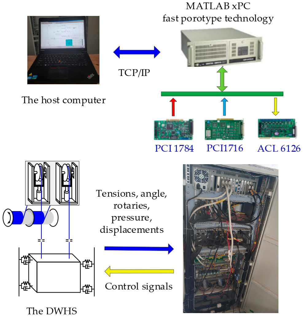
It can be seen from Figure 6 that the conveyance is driven by two winding drums, whose revolving speeds can be acquired by two rotary encoders. The counterclockwise angle and two wire rope tensions will be measured by the angle sensor and two force sensors in real time respectively, when the DWHS is in an operation. When two hydraulic cylinders actively pull or push two movable head sheaves, two displacement sensors will measure the displacements of two hydraulic cylinders are measured by two high precision magnetostrictive displacement sensor in real time to feed back to the control system.
Figure 4 presents the operating principle of the control system. The encoder acquisition card PCI-1784, analog data acquisition(A/D) card PCI-1716, and the analog data output board(D/A) card ACL-6126 are all installed in the real-time controller. Analog control signals (−10 V~+10 V) output from the D/A card ACL-6126, which will be transformed in to −40 mA~+40 mA by the signal conditioning system, are sent to four servo valves to control two hydraulic cylinders for driving two movable headgear sheaves and two hydraulic winches for driving two wire ropes. As well, 4~20 mA current analog signals, which including two hydraulic cylinder displacements, two wire rope tensions, conveyance angle, and four hydraulic cylinder chamber pressures, which need to be transformed into 2~10 V voltage analog signals by the signal conditioning system, are acquired by two A/D card PCI-1716s. As well, the board PCI-1784 is utilized to obtain two impulse signals of rotary encoders that are employed to measure the two hydraulic winches revolving speeds and transform them into digital signals. Control strategies, which are programmed by MATLAB/Simulink, are downloaded to the target computer to realize real-time control. The host computer is communicated with the target computer by Ethernet. The operating frequency of the control system is 1000Hz.

4.2. Comparative Experimental Results

Table 2 shows key parameters of the DWHS in experiments.
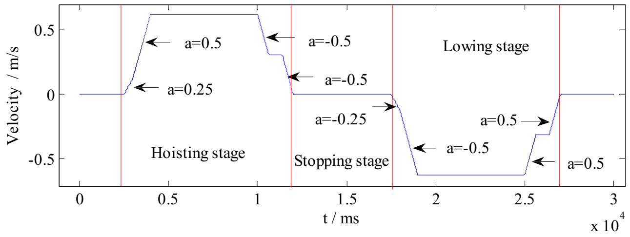
The DWHS operates on a six-stage velocity shown in Figure 7.
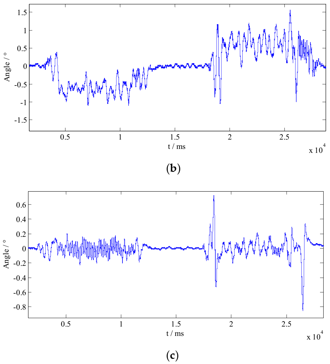
To study the superiority of the proposed controller compared to the traditional PI controller, a series of experiments are carried out on the DWHS experiment setup. Since the control task is to realize the leveling control of the conveyance, the reference angle is set as 0 degree. The comparison results with two different controllers are given in Figure 8. The detail distinctions between two controllers are explained as follows. Control parameters of the PI controller and the hybrid control algorithm are given in Table 3.
(1) PI controller: Control input signals u1 and u2 are calculated by the counterclockwise rotation angle θc and expressed as u = Kpθc + KIθc = u1 = −u2. As well, the EHSS is a proportional controller.
(2) The hybrid controller: The control inputs u1 and u2 are obtained by the FBC according to the dynamical model of the hoist, are inputted into the EHSS. The DOBIBC for the EHSS will track two control inputs according to the dynamic model and the real control law of the EHSS.
Figure 8 presents the conveyance counterclockwise rotation angle in the operation of the DWHS. The conveyance counterclockwise rotation angle monotonously increases with fluctuations at the hoisting stage while the controllers are not employed, after the stop phase, then monotonously decreases to zero with fluctuations at the lowering stage. As well, its range is [0°~3.981°]. With the PI controller, the angle is controlled in the range of [−1.1°~1.58°]. When the hybrid controller is utilized to make tensions of two wire ropes balance, the rotation angle fluctuates around with 0° the range of [−0.85°~0.73°]. From above, the hybrid controller > the PI controller.
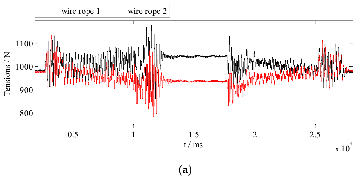
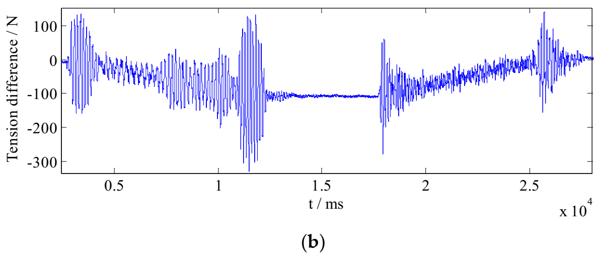
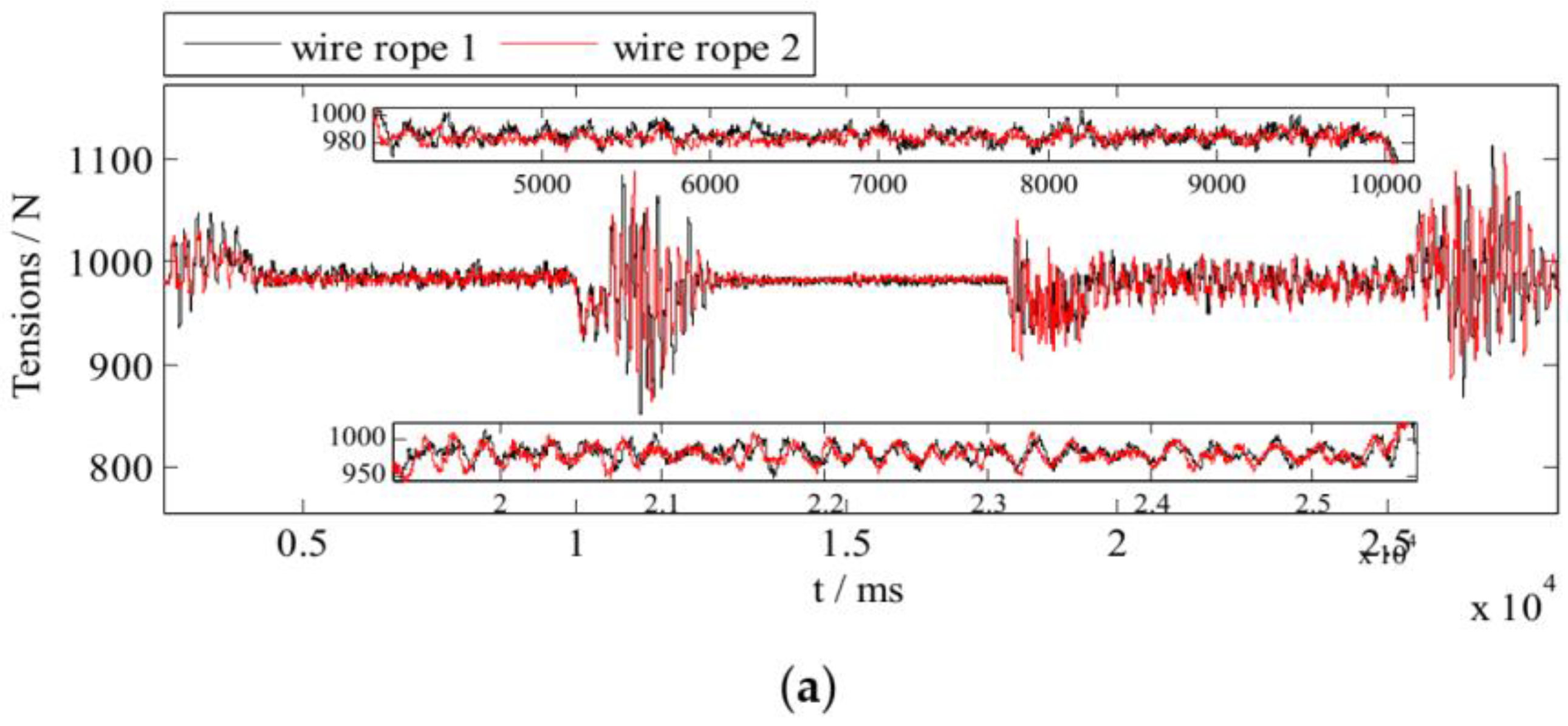
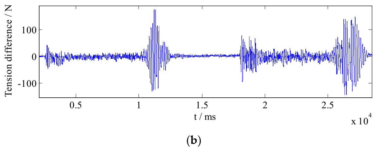
Figure 9, Figure 10 and Figure 11 present the two wire rope tensions. As shown in Figure 8, while the controllers are not employed, the tension difference of two wire ropes monotonously increases with fluctuations at the hoisting phase, after the stop phase, and then monotonously decreases with fluctuations at the lowering stage. As well, its varying range is [−143.13 N~330 N]. From Figure 9, it can be observed that the PI controller can coordinate two wire rope tensions, however, fluctuation ranges of two tensions are [900 N~1000 N] in the uniform stage of the hoisting stage and [900 N~1040 N] in the uniform stage of the lowering stage, and there still is a certain tension difference with the range of [−220.91 N~207.93 N]. As is shown in Figure 10, when the hybrid controller is utilized to coordinate two tensions, two tensions fluctuate nearly around the ideal value (980 N) at the uniform stage of the hoisting stage and their fluctuation ranges are [950 N~1000 N] at the uniform stage of the lowering stage. Its tension difference range is [143.38 N~177.14 N]. Therefore, the hybrid controller exhibits a better performance than the PI controller.
The root mean square error (RMSE) is employed to illustrate the efficiency of two controllers.
RMSE = i n R i n , i R o u t , i 2 n
where R i n , i represents the reference signal, R o u t , i represents the feedback signal of sensors, n represents the length of the signal. Table 4 shows the RMSE of two controllers.
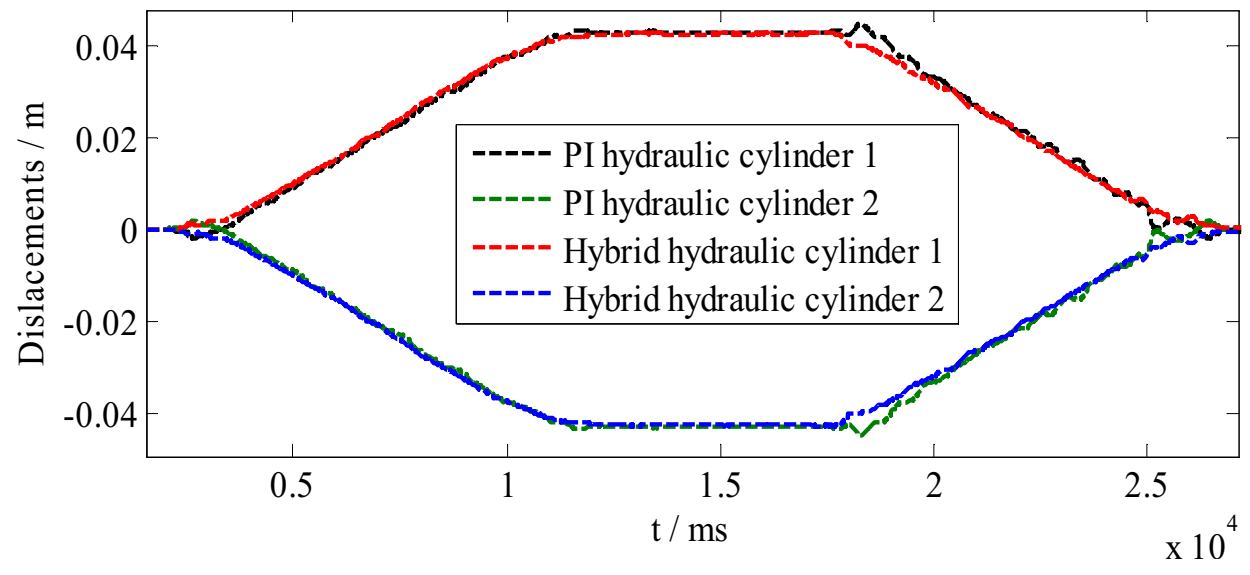
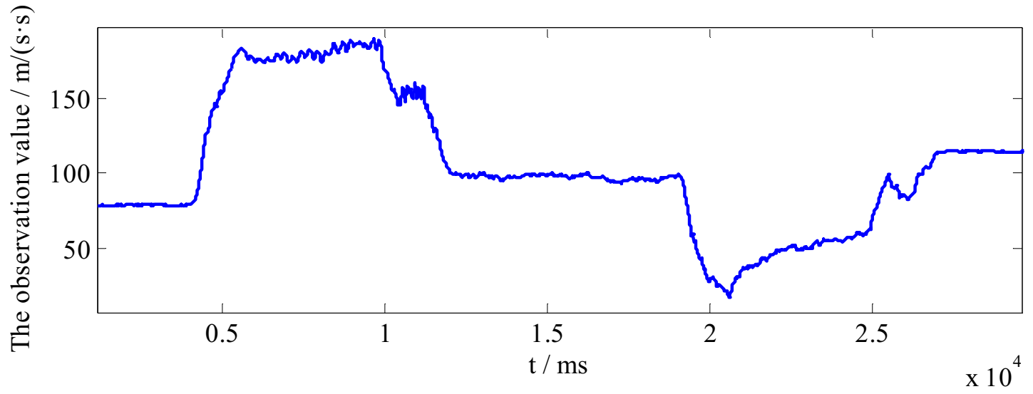
Figure 12 presents the two hydraulic cylinder displacements with two controllers. From Figure 12, it can be known that displacements of the hybrid controller are smoother than that of the PI controller while coordinating the two wire rope tensions of the DWHS. Figure 13 presents the observation value of the disturbance observer.

5. Conclusions

In order to coordinate two wire rope tensions of the DWHS, a hybrid controller combining the flatness-based control and a disturbance observer based integral backstepping control is proposed. As well, comparative experimental results illustrate that the hybrid controller can make a better performance on wire rope tension of the DWHS than the conventional PI controller. The results of this work may be summarized as follows.
(1)
According to the dynamic models of the hoist and the EHSS, the overall model of the DWHS is presented and expressed with a state space formulation.
(2)
According to the state representation of the hoisting system, the FBC for hoisting system is presented. As well, in order to compensate the constant disturbance of the hoisting system, an integral of the system angle state is define and utilized in the FBC controller design. According to the state representation of the EHSS and the disturbance observer, the DOBIBC design is explicitly presented and the virtual control law in each step controller design is analyzed. Finally, the stability of the overall closed loop is proved.
(3)
The experimental setup is expressed to indicate the efficiency of the proposed hybrid control method. Comparative experiment results illustrate that the hybrid control method make a better work on decreasing the tension difference of two wire ropes than that of the conventional PI controller, which guarantees the safety of the DWHS.
In the future, we want to develop our research from the following four aspects:
1)
Develop more hybrid controllers combining different controllers for the hoisting system and the EHSS. Study control characteristics of the hoisting system and the EHSS furtherly so that we can develop corresponding different controllers to improve the coordination of two tensions;
2)
Establish the force control model of two wire ropes adjusted by two hydraulic cylinders, consequently, based on the model, we can design different controllers to coordinate two tensions;
3)
To reduce the number of attached sensors for simplifying control system hardware, it is interesting to take velocity or pressure sensorless control based on several types of observer into consideration for the energy saving with performance tradeoff;
4)
Based on these research results, we can develop different controllers for tension coordination control of multi-rope friction hoisting systems (generally four wire ropes or six wire ropes).

Author Contributions

Original draft preparation and editing, X.L.; performing tests and investigations, X.L., Z.Z.; analyzing the results and reviewing the article; G.S., Y.T.; supervision and review writing, X.L. All authors have read and agreed to the published version of the manuscript.

Funding

This research was supported by the Fundamental Research Funds for the Central Universities under Grant 2019QNA10.

Institutional Review Board Statement

Not applicable.

Informed Consent Statement

Not applicable.

Data Availability Statement

Not applicable.

Conflicts of Interest

The authors declare no conflict of interest.

Appendix A

According to the Figure 2, there have the displacement on tangent point between left catenary rope and the left floating headgear sheave that is defined as l r 1 u 1 sin α 1 . Then, the displacement on tangent point between the floating headgear sheave and the vertical hoisting rope can be defined as l r 1 +   1 + sin α 1 u 1 .
Defining unit length left catenary rope displacement at a distance of s as
s l 1 = l r 1 +   l r 1 u 1 sin α 1 l r 1 s l 11
In a similar way, the unit length left vertical hoisting rope displacement at a distance of y can be written as
y l 1 = l r 1 + ( 1 + sin α 1 ) u 1 +   x c a 1 θ c l r 1 ( 1 + sin α 1 ) u 1 y l 12
Referring to the Equations (A1) and (A2), the kinetic energy of the left catenary rope and the left vertical hoisting rope can be formulated as follows, respectively
T l 11 = 1 2 ρ 0 l 11 s ˙ l 1 2 d s                   = 1 2 ρ 0 l 11 l ˙ r 1 + l ˙ r 1 u ˙ 1 sin α 1 l ˙ r 1 s l 11 2 d s = 1 6 ρ l 11 l ˙ r 1 2 + l ˙ r 1 l ˙ r 1 u ˙ 1 sin α 1 + l ˙ r 1 u ˙ 1 sin α 1 2
T l 12 = 1 2 ρ 0 l 12 y ˙ l 1 2 d y = 1 2 ρ 0 l 12 l ˙ r 1 + ( 1 + sin α 1 ) u ˙ 1 +   x ˙ c a 1 θ ˙ c l ˙ r 1 ( 1 + sin α 1 ) u ˙ 1 y l 12 2 d y = 1 6 ρ l 12 l ˙ r 1 + ( 1 + sin α 1 ) u ˙ 1 2 + x ˙ c a 1 θ ˙ c l ˙ r 1 + ( 1 + sin α 1 ) u ˙ 1 + x ˙ c a 1 θ ˙ c 2
where ρ is the mass per unit length wire rope. The displacement on tangent point between right catenary rope and the right floating headgear sheave is l r 2 u 2 sin α 2 , defining unit length right catenary rope displacement at a distance of as
s l 2 = l r 2 +   l r 2 u 2 sin α 2 l r 2 s l 12
The displacement on tangent point between the floating headgear sheave and the vertical hoisting rope can be defined as l r 2 + 1 + sin α 2 u 2 , the displacement of the unit length left vertical hoisting rope at a distance of y can be then written as
y l 2 = l r 2 + ( 1 + sin α 2 ) u 2 +   x c + a 2 θ c l r 2 ( 1 + sin α 2 ) u 2 y l 22
The kinetic energy of the right catenary rope and right vertical hoisting rope are given as follows, respectively
T l 21 = 1 2 ρ 0 l 21 s ˙ l 2 d s                 = 1 2 ρ 0 l 21 l ˙ r 2 + l ˙ r 2 u ˙ 2 sin α 2 l ˙ r 2 s l 21 2 d s = 1 6 ρ l 21 l ˙ r 2 2 + l ˙ r 2 l ˙ r 2 u ˙ 2 sin α 2 + l ˙ r 2 u ˙ 2 sin α 2 2
T l 22 = 1 2 ρ 0 l 22 y ˙ l 2 d y = 1 2 ρ 0 l 22 l ˙ r 2 + ( 1 + sin α 2 ) u ˙ 2 +   x ˙ c + a 2 θ ˙ c l ˙ r 2 ( 1 + sin α 2 ) u ˙ 2 y l 22 2 d y = 1 6 ρ l 22 l ˙ r 2 + ( 1 + sin α 2 ) u ˙ 2 2 + x ˙ c + a 2 θ ˙ c l ˙ r 2 + ( 1 + sin α 2 ) u ˙ 2 + x ˙ c + a 2 θ ˙ c 2
The kinetic energy of the left and right floating headgear sheaves is expressed as
T h 1 = 1 2 m 1 u ˙ 1 2 + 1 2 I 1 l ˙ r 1 r 1 2
T h 2 = 1 2 m 2 u ˙ 2 2 + 1 2 I 2 l ˙ r 2 r 2 2
where m 1 and m 2 the of the left and right movable headgear sheave mass, respectively, r 1 and r 2 are the left and right movable headgear sheave radius, respectively, and I 1 and I 2 are the left and right movable headgear sheaves moment of inertias, respectively. Then, the conveyance kinetic energy is formulated as
T c = 1 2 m c x ˙ c 2 + 1 2 m c y ˙ c 2 + 1 2 I c θ ˙ c 2
where m c is the conveyance and goods mass and I c is the conveyance and goods rotational inertias. The potential energy of the rope composed of the left catenary rope and the left vertical hoisting rope can be expressed as following
U l 1 = 1 2 ρ g l 12 x c a 1 θ c   +   l r 1 + ( 1 + sin α 1 ) u 1 1 2 ρ g l 11 l r 1 + u 1 sin α 1 + l r 1 sin α 1 + 1 2 k 11 l r 1 u 1 sin α 1 l r 1 2 + 1 2 k 12 x c a 1 θ c l r 1 ( 1 + sin α 1 ) u 1 2
Likewise, the right rope potential energy can be expressed as
U l 2 = 1 2 ρ g l 22 x c + a 2 θ c   +   l r 2 + ( 1 + sin α 2 ) u 2 1 2 ρ g l 21 l r 2 + u 2 sin α 2 + l r 2 sin α 2 + 1 2 k 21 l r 2 u 2 sin α 2 l r 2 2 + 1 2 k 22 x c + a 2 θ c l r 2 ( 1 + sin α 2 ) u 2 2
where k 11 and k 21 are the left and right catenary rope stiffness, respectively, k 12 and k 22 are the left and right vertical hoisting rope stiffness, respectively. The left and right floating headgear sheaves potential energy are expressed as
U h 1 = m 1 g u 1
U h 2 = m 2 g u 2
The conveyance system potential energy composed of the conveyance and shaft guide potential energy is formulated as follows
U c = m c g x c + 1 2 k s 1 y c b 1 θ c 2 + 1 2 k s 2 y c + b 2 θ c 2 + 1 2 k s 3 y c b 1 θ c 2 + 1 2 k s 4 y c + b 2 θ c 2
The left and right ropes Rayleigh dissipation functions are expressed as
D l 1 = 1 2 c 11 l ˙ r 1 u ˙ 1 sin α 1 l ˙ r 1 2 + 1 2 c 12 x ˙ c a 1 θ ˙ c l ˙ r 1 ( 1 + sin α 1 ) u ˙ 1 2
D l 2 = 1 2 c 21 l ˙ r 2 u ˙ 2 sin α 2 l ˙ r 12 2 + 1 2 c 22 x ˙ c + a 2 θ ˙ c l ˙ r 2 ( 1 + sin α 2 ) u ˙ 2 2
where c 11 and c 21 are the left and right catenary rope damping coefficients, respectively, c 12 and c 22 are the left and right vertical hoisting rope damping coefficients, respectively.
The conveyance system Rayleigh dissipation function is given as
D c = 1 2 c s 1 y ˙ c b 1 θ ˙ c 2 + 1 2 c s 2 y ˙ c + b 2 θ ˙ c 2 + 1 2 c s 3 y ˙ c b 1 θ ˙ c 2 + 1 2 c s 4 y ˙ c + b 2 θ ˙ c 2
Then, the hoisting system kinetic energy, the potential energy and Rayleigh dissipation function can be given by
T = T l 11 + T l 12 + T l 21 + T l 22 + T h 1 + T h 2 + T c
U = U l 1 + U l 2 + U h 1 + U h 2 + U c
D = D l 1 + D l 2 + D c
Make the hoisting direction as positive, the vertical hoisting wire rope lengths In the course of the assignment can be expressed as
l 12 = l 120 l r 1 u 1 sin ( α 1 )
l 22 = l 220 l r 2 u 2 sin ( α 2 )
where l 120 and l 220 are two vertical hoisting wire rope initial lengths, l r 1 and l r 2 are the twin-drum rotation lengths, u 1 and u 2 are two floating headgear sheaves displacements, α 1 and α 2 are angles between two catenaries and horizontal plane, a 1 is the horizontal distance between the junction of two wire ropes, a 2 is the horizontal distance between conveyance and the barycenter of conveyance and goods. In this work, only consider the case where there is no offset load, set a 1 = a 2 ; k s 1 , k s 2 , k s 3 , k s 4 are the four pairs of spring-damper model lateral equivalent spring stiffness, c s 1 , c s 2 , c s 3 , c s 4 are the four pairs of spring-damper model lateral equivalent damping, and b 1 and b 2 are the longitudinal distance between the top and bottom surfaces of the conveyance and the barycenter of the conveyance.
In order to obtain the expected of moveable heave displacement, a hydraulic cylinder driven by a proportional servo-valve is utilized in this paper, whose working principle is shown in Figure 3, where Q 1 and Q 2 are the flow into and out of the chamber of hydraulic cylinder, which can be written as
Q 1 = C d w x v 2 ρ ( p s p 1 )
Q 2 = C d w x v 2 p 2 ρ
where x v is the proportional servo-valve spool displacement, p 1 and p 2 are the two chamber pressures, w is the constant area gradient of the proportional servo-valve orifices, C d is the discharge coefficient, ρ is the fluid mass density, p s is the hydraulic supply pressure, P L is the load pressure, written as P L = p 1 p 2 . Ignoring the impact of the leak on hydraulic cylinder and the compression of oil, the linearized load flow Q L can be formulated as
Q L = K q x v K c P L
where K q and K c are the linearized flow gain coefficient, which are formulated as K q = Q L / x v = C d w ( p s p L ) / ρ and K c = Q L / P L = C d w x v ( p s P L ) / ρ / 2 ( p s P L ) . The load flow Q L can be given as
Q L = A p d x p d t + C t p P L + V t 4 β e d P L d t
where A p is the hydraulic cylinder effective area, x p is the piston displacement and d x p / d t is the actuator piston velocity, C t p is the internal leakage coefficient, C e p is the external leakage coefficient, C t p is the total leakage coefficient of the actuator that defined by C t p = C i p + C e p / 2 , V t is the hydraulic cylinder total volume, and β e is the effective bulk modulus. Ignoring the oil mass and nonlinear load such as dry friction, the piston dynamics can be described by Newton’s second law
P L = 1 A p m t d 2 x p d t 2 + B c d x p d t
where m t is the of the actuator piston total mass, the load and the specimen, and B c is the viscous damping coefficient of the piston and the payload.

References

  1. Li, X.; Zhu, Z.C.; Shen, G. A switching-type controller for wire rope tension coordination of electro-hydraulic-controlled double-rope winding hoisting systems. Proc. Inst. Mech. Eng. Part I J. Syst. Control Eng. 2016, 230, 1126–1144. [Google Scholar] [CrossRef]
  2. Carbogno, A. Mine hoisting in deep shafts in the 1st half of 21st Century. Acta Montan. Slov. 2002, 7, 188–192. [Google Scholar]
  3. Zhu, Z.C.; Li, X.; Shen, G.; Zhu, W.D. Wire rope tension control of hoisting systems using a robust nonlinear adaptive backstepping control scheme. ISA Trans. 2018, 72, 256–272. [Google Scholar] [CrossRef] [PubMed]
  4. Ye, Y.; Yin, C.B.; Gong, Y.; Zhou, J.J. Position control of nonlinear hydraulic system using an improved PSO based PID controller. Mech. Syst. Signal Process. 2017, 83, 241–259. [Google Scholar] [CrossRef]
  5. De Luca, A. Decoupling and feedback linearization of robots with mixed rigid/elastic joints. Int. J. Robust Nonlinear Control 2015, 8, 965–977. [Google Scholar] [CrossRef]
  6. Choi, Y.S.; Choi, H.H.; Jung, J.W. Feedback linearization direct torque control with reduced torque and flux ripples for IPMSM drives. IEEE Trans. Power Electron. 2015, 31, 3728–3737. [Google Scholar] [CrossRef]
  7. de Jesús Rubio, J. Robust feedback linearization for nonlinear processes control. ISA Trans. 2018, 74, 155–164. [Google Scholar] [CrossRef]
  8. Kumar, P.R.; Chalanga, A.; Bandyopadhyay, B. Smooth integral sliding mode controller for the position control of Stewart platform. ISA Trans. 2015, 58, 543–551. [Google Scholar] [CrossRef]
  9. Asad, M.; Bhatti, A.I.; Iqbal, S.; Asfia, Y. A smooth integral sliding mode controller and disturbance estimator design. Int. J. Control Autom. Syst. 2015, 13, 1326–1336. [Google Scholar] [CrossRef]
  10. Jitendra, K.; Vineet, K.; Kps, R. Design of robust fractional order fuzzy sliding mode pid controller for two-link robotic manipulator system. J. Intell. Fuzzy Syst. 2018, 35, 5301–5315. [Google Scholar]
  11. Rubio, J.D.J. Hybrid controller with observer for the estimation and rejection of disturbances. ISA Trans. 2016, 65, 445–455. [Google Scholar] [CrossRef]
  12. Liu, H.; Li, D.; Xi, J.; Zhong, Y. Robust attitude controller design for miniature quadrotors. Int. J. Robust Nonlinear Control 2016, 26, 681–696. [Google Scholar] [CrossRef]
  13. Sanz, R.; Garcia, P.; Albertos, P.; Zhong, Q.C. Robust controller design for input-delayed systems using predictive feedback and an uncertainty estimator. Int. J. Robust Nonlinear Control 2017, 27, 1826–1840. [Google Scholar] [CrossRef]
  14. Shi, X.; Williams, S.; Chatzis, N. A robust algorithm to test the observability of large linear systems with unknown parameters. Mechal. Syst. Signal Process. 2021, 157, 107633. [Google Scholar] [CrossRef]
  15. Rubio, J.D.J.; Ochoa, G.; Mújica-Vargas, D.; García, E.; Balcazar, R.; Elias, I.; Cruz, D.R.; Juarez, C.F.; Aguilar, A.; Novoa, J.F. Structure regulator for the perturbations attenuation in a quadrotor. IEEE Access 2019, 7, 138244–138252. [Google Scholar] [CrossRef]
  16. Liu, Y.J.; Lu, S.; Li, D.; Tong, S. Adaptive controller design-based ABLF for a class of nonlinear time-varying state constraint systems. IEEE Trans. Syst. Man Cybern. Syst. 2016, 47, 1546–1553. [Google Scholar] [CrossRef]
  17. Li, Z.; Chen, Z.; Fu, J.; Sun, C. Direct adaptive controller for uncertain MIMO dynamic systems with time-varying delay and dead-zone inputs. Automatica 2016, 63, 287–291. [Google Scholar] [CrossRef] [Green Version]
  18. Chen, X.; Zhu, Z.; Shen, G.; Li, W. Tension coordination control of double-rope winding hoisting system using hybrid learning control scheme. Proc. Inst. Mech. Eng. Part I J. Syst. Control Eng. 2019, 233, 1265–1281. [Google Scholar] [CrossRef]
  19. Hoshyar, M.; Mola, M. Full adaptive integral backstepping controller for interior permanent magnet synchronous motors. Asian J. Control 2018, 20, 768–779. [Google Scholar] [CrossRef]
  20. Adekanle, O.; Guisser, M.; Abdelmounim, E.; Aboulfatah, M. Integral Backstepping controller combined with High Gain Observer for the optimization of grid-connected Doubly-Fed Induction Generator. In Proceedings of the 2017 International Conference on Wireless Technologies, Embedded and Intelligent Systems (WITS), Fez, Morocco, 19–20 April 2017; pp. 1–7. [Google Scholar]
  21. Herzig, N.; Moreau, R.; Redarce, T.; Abry, F.; Brun, X. Nonlinear position and stiffness Backstepping controller for a two Degrees of Freedom pneumatic robot. Control Eng. Pract. 2018, 73, 26–39. [Google Scholar] [CrossRef]
  22. Jia, Z.; Yu, J.; Mei, Y.; Chen, Y.; Shen, Y.; Ai, X. Integral backstepping sliding mode control for quadrotor helicopter under external uncertain disturbances. Aerosp. Sci. Technol. 2018, 68, 299–307. [Google Scholar] [CrossRef]
  23. Nikdel, N.; Badamchizadeh, M.A.; Azimirad, V.; Nazari, M.A. Adaptive backstepping control for an n-degree of freedom robotic manipulator based on combined state augmentation. Robot. Comput. Integr. Manuf. 2017, 44, 129–143. [Google Scholar] [CrossRef]
  24. Fliess, M.; Lévine, J.; Martin, P.; Rouchon, P. Flatness and defect of non-linear systems: Introductory theory and examples. Int. J. Control 1995, 61, 1327–1361. [Google Scholar] [CrossRef] [Green Version]
  25. Kim, W.; Won, D.; Tomizuka, M. Flatness-based nonlinear control for position tracking of electrohydraulic systems. IEEE/ASME Trans. Mechatron. 2015, 20, 197–206. [Google Scholar] [CrossRef]
  26. Zheng, D.; Xu, H. Adaptive backstepping-flatness control based on an adaptive state observer for a torque tracking electrohydraulic system. IEEE/ASME Trans. Mechatron. 2016, 21, 2440–2452. [Google Scholar] [CrossRef]
  27. Houari, A.; Renaudineau, H.; Martin, J.P.; Pierfederici, S.; Meibody-Tabar, F. Flatness-based control of three-phase inverter with output LC filter. IEEE Trans. Ind. Electron. 2012, 59, 2890–2897. [Google Scholar] [CrossRef]
  28. Rodriguez-Fortun, J.M.; Orus, J.; Alfonso, J.; Gimeno, F.B.; Castellanos, J.A. Flatness-based active vibration control for piezoelectric actuators. IEEE/ASME Trans. Mechatron. 2013, 18, 221–229. [Google Scholar] [CrossRef]
  29. Zang, W.; Shen, G.; Rui, G.; Li, X.; Li, G.; Tang, Y. A flatness-based nonlinear control scheme for wire tension control of hoisting systems. IEEE Access 2019, 7, 146428–146442. [Google Scholar] [CrossRef]
  30. Zolfaghari, M.; Abedi, M.; Gharehpetian, G.B.; Guerrero, J.M. Flatness-Based Decentralized Control of Bidirectional Interlink Power Converters in Grid-Connected Hybrid Microgrids Using Adaptive High-Gain PI-Observer. IEEE Syst. J. 2021, 15, 478–486. [Google Scholar] [CrossRef]
  31. Jing, C.; Xu, H.; Song, X.; Lu, B. Adaptive extended state observer-based flatness nonlinear output control for torque tracking of electrohydraulic loading system. Trans. Inst. Meas. Control 2018, 40, 2999–3009. [Google Scholar] [CrossRef]
  32. Won, D.; Kim, W.; Shin, D.; Chung, C.C. High-gain disturbance observer-based backstepping control with output tracking error constraint for electro-hydraulic systems. IEEE Trans. Control Syst. Technol. 2014, 23, 787–795. [Google Scholar] [CrossRef]
  33. Guo, K.; Wei, J.; Fang, J.; Feng, R.; Wang, X. Position tracking control of electro-hydraulic single-rod actuator based on an extended disturbance observer. Mechatronics 2015, 27, 47–56. [Google Scholar] [CrossRef]
  34. Tian, D.; Xu, R.; Sariyildiz, E.; Gao, H. An Adaptive Switching-Gain Sliding-Mode-Assisted Disturbance Observer for High-Precision Servo Control. IEEE Trans. Ind. Electron. 2021. [Google Scholar] [CrossRef]
  35. Won, D.; Kim, W.; Tomizuka, M. High-gain-observer-based integral sliding mode control for position tracking of electrohydraulic servo systems. IEEE/ASME Trans. Mechatron. 2017, 22, 2695–2704. [Google Scholar] [CrossRef]
  36. Guo, Q.; Yu, T.; Jiang, D. High-gain observer-based output feedback control of single-rod electro-hydraulic actuator. IET Control Theory Appl. 2015, 9, 2395–2404. [Google Scholar] [CrossRef]
  37. Chen, F.; Lei, W.; Zhang, K.; Tao, G.; Jiang, B. A novel nonlinear resilient control for a quadrotor UAV via backstepping control and nonlinear disturbance observer. Nonlinear Dyn. 2016, 85, 1281–1295. [Google Scholar] [CrossRef]
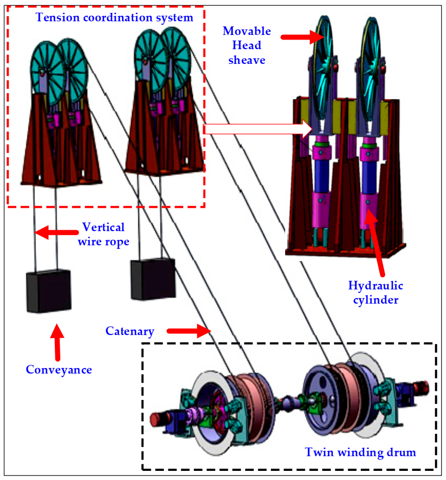
Figure 1. The DWHS.
Figure 1. The DWHS.
Symmetry 13 00716 g001
Figure 2. The schematic diagram of the DWHS.
Symmetry 13 00716 g002
Figure 3. The schematic diagram of the EHSS.
Symmetry 13 00716 g003
Figure 4. The overall architecture of the control system.
Symmetry 13 00716 g004
Figure 5. The DWHS experiment setup.
Symmetry 13 00716 g005
Figure 6. The control system operating principle.
Symmetry 13 00716 g006
Figure 7. Six-stage speed planning of the DWHS.
Symmetry 13 00716 g007
Figure 8. The conveyance counterclockwise rotation angle. (a) without any a controller, (b) with the PI controller, (c) with the hybrid controller.
Symmetry 13 00716 g008aSymmetry 13 00716 g008b
Figure 9. Two wire rope tensions without any a controller. (a) Two wire rope tensions without any a controller, (b) tension difference without any a controller.
Symmetry 13 00716 g009aSymmetry 13 00716 g009b
Figure 10. Two wire rope tensions with the PI controller. (a) Two wire rope tensions with the PI controller, (b) tension difference with the PI controller.
Symmetry 13 00716 g010
Figure 11. Two wire rope tensions with the hybrid controller. (a) Tensions of two wire ropes with the hybrid controller, (b) tension difference with the hybrid controller.
Symmetry 13 00716 g011aSymmetry 13 00716 g011b
Figure 12. Two hydraulic cylinders displacements.
Symmetry 13 00716 g012
Figure 13. The observation value of the disturbance observer.
Symmetry 13 00716 g013
Table 1. Main structural parameters of the experiment setup.
Structural Parameters/UnitValues
Height of the experiment setup/m7
Length of the flexible guide/m6
Width of the experiment setup/m3.4
Length of the experiment setup/m4.4
Weight of the conveyance/Kg200
Size of the weight stacks/m0.375 × 0.375 × 0.125
Table 2. Parameters of the DWHS.
ParametersValuesParametersValuesParametersValues
Ap1.88 × 10−3 m2mc200 kgBp25,000 N(m/s)
b10.0625 mb20.0625 ma10.1575 m
a20.1575 mVt0.96 × 10−3 m3Ctl4.6 × 10−17 m3/s/Pa
Pr6 × 106 Paumax10 VIc3.307 kg·m2
Kc2 × 10−12 m3/s/PaPs15 × 106 Paρ0.417 kg/m
Ksv4 m3/s/AQr38 L/minβe6.9 × 108 Pa
l120, l2206 m
Table 3. Control gains of controllers.
The PI Controller
The hoisting systemThe EHSS
Kp0.15Ksp17
KI0.5KsI0
The Hybrid Controller
The hoisting system
The FBC
The EHSS
The DOBIBC
k125kp1600
k23 × 107kI15
k31.7 × 105k41000
k51000
b20
Table 4. RMSE of two controllers.
ControllersPeak ErrorRMSE
The counterclockwise rotation angle
The PI controller1.58°0.4863
The hybrid controller0.85°0.1067
The tension difference
The PI controller207.93 N36.7085
The hybrid controller177.14 N25.5525
Publisher’s Note: MDPI stays neutral with regard to jurisdictional claims in published maps and institutional affiliations.