Article

Active Suppression of Piezoelectric Ringing in Pockels Cells for Laser Cavity Application

by
Giedrius Sinkevicius
1,2,*,
Algirdas Baskys
1,2 and
Gintaras Tamošauskas
3
1
Department of Functional Materials and Electronics, Center for Physical Sciences and Technology, Saulėtekio av. 3, LT-10257 Vilnius, Lithuania
2
Department of Computer Science and Communications Technologies, Vilnius Gediminas Technical University, Naugarduko St. 41, LT-03227 Vilnius, Lithuania
3
Laser Research Center, Vilnius University, Saulėtekio ave. 10, LT-10223 Vilnius, Lithuania
*
Author to whom correspondence should be addressed.
Symmetry 2021, 13(4), 677; https://doi.org/10.3390/sym13040677
Submission received: 6 March 2021 / Revised: 9 April 2021 / Accepted: 11 April 2021 / Published: 14 April 2021

Abstract

:
Pockels cells used as electro-optical modulators in high-power high-repetition lasers suffer from piezoelectric ringing phenomenon due to piezoelectric properties of the crystals. A new method for active suppression of the piezoelectric ringing in Pockels cells is proposed in this work. It is based on symmetric control of Pockels cell using burst of short positive and negative voltage pulses with the same amplitude instead of a single long pulse for light polarization modulation. Rising and falling edges of pulses of the burst induce symmetrical acoustic waves of the opposite phase and cancel the piezoelectric ringing of the crystal. A new high voltage driver capable of generating positive and negative pulses of tens of nanoseconds of 3 kV magnitude was developed for this purpose. The amplitude of laser beam intensity pulsations caused by the piezoelectric ringing can be reduced up to five times when active suppression method is used for the deuterated potassium dihydrogen phosphate (DKDP) Pockels cell. Such crystals like DKDP, LiNbO3, and LiTaO3 may benefit from the proposed method and find new use in lasers of high repetition rate where piezoelectric ringing is a major limiting factor.

1. Introduction

High power laser systems are increasingly used in material processing. The so-called Q-switching technique is used to produce high power laser pulses. Many methods for implementation of Q-switching have been developed [1,2,3,4,5,6,7,8]. However, for high laser power applications only a few methods are applied. One of the most commonly used methods is based on electro-optical modulators, also known as Pockels cells. Pockels cells excel among other modulator types due to their high optical contrast ratio [9], which is the main parameter of the electro-optic modulator.
To control the Pockels cell, high voltage (few kilovolt) pulses have to be applied. Voltage pulses change the refractive index of the Pockels cell material and, as a consequence, induces changes in the polarization of the laser beam [10,11,12]. Change in the polarization changes the intensity of the output beam after the polarizer, which is a part of the Q-switching system based on the Pockels cell. Optical contrast ratio is measured by placing a Pockels cell between crossed polarizers (Figure 1a). Polarizer splits the transmitted beam into two beams and directs them in different directions, depending on the polarization of incident beam. The contrast ratio is determined as a ratio of split beams’ intensities [13,14]. Beam intensity is measured using a detector that produces a signal (voltage Ud) proportional to the light intensity and this signal we call optical response. Voltage of the detector proportional to the optical response of the Pockels cell when a continuous wave laser is used, is presented in Figure 1a.
Pockels cells mainly find application as an electrically controlled optical gate when combined with the polarizer. This is a very effective method to achieve nanosecond pulse generation in lasers. Pockels cells are used inside regenerative amplifiers and out of the cavity to manipulate pulses such as for single pulse selection, pulse train formation, and repetition division. However, a phenomenon called piezoelectric ringing significantly reduces the optical contrast ratio in the Pockels cells. It is caused by acoustic waves inside the crystal, which are induced by high voltage pulses used to control the Pockels cell [15,16,17,18]. Acoustic waves cause modification of the refractive index of the crystal, thus modulating polarization of the laser beam and, as a result, reduce the optical contrast ratio [19,20,21,22,23].
In this paper we address the problem of the piezoelectric ringing, which arises when a laser operates at high switching frequency in the range from 10 kHz to 10 MHz. At high switching frequency, acoustic waves excited in the Pockels cell crystal have no time to naturally dissipate until the next high voltage pulse is applied, and, therefore, the contrast decreases [19,20,21,22,23]. Since the processes of electro-optical switching and generation of acoustic wave are of different response symmetry, it is possible to keep the first one going and to cancel the second one if mean voltage is zero or positive–negative control symmetry is achieved. Though this is a simplistic explanation, it is at the core of present research.
Two situations are presented in Figure 1 to demonstrate the influence of the piezoelectric ringing phenomenon on the operation of the Pokels cell: first, when the cell is outside the laser cavity (extracavity); second, when it is inside the cavity (intracavity) [10,12,24]. The scales of the axis in the Figure 1 are given for example purposes only.
Extracavity mode (Figure 1a) is used to generate the train of optical pulses. In this mode, the laser system is in one of the following states: “active time”, when voltage is not applied to the Pockels cell (there is no optical pulse), and “idle time”, when voltage is applied to the Pockels cell (optical pulse is present). In the active time mode high voltage is applied to the Pockels cell, which allows the optical beam to propagate directly through the polarizer. Optical pulse intensity is measured using the detector, which provides the voltage Ud proportional to light intensity. The graphs presented in Figure 1a demonstrate how piezoelectric ringing can disturb the train of optical pulses and, as a consequence, reduce the optical contrast.
Intracavity operating mode (Figure 1b) presumes the amplification of the optical signal. During the “active time” the single optical pulse of pulsed seed laser is trapped between the two mirrors and is amplified by the lasing medium (not shown in the picture) with each round trip. The amplified pulse circulating inside the two mirrors is shown in Figure 1b as an “intracavity pulse”. It is necessary to ensure high optical contrast in the intracavity operating mode to achieve high gain and prevent false seeding. Fast high voltage driver can change the Pockels cell voltage polarity without tiggering false seeding. However, optical contrast has been reduced by piezoelectric ringing and cause the false seeding shown in Figure 1b.
A new method for active suppression of the piezoelectric ringing in Pockels cells is proposed in this work. It is based on symmetric control of Pockels cells using burst of short (tens of nanoseconds) positive and negative high voltage pulses with the same amplitude, instead of a single continuous pulse, as is the current practice. We suggest that the falling edges of short pulses in the burst induce symmetrical acoustic waves of the opposite phase, which could cancel the piezoelectric ringing in the Pockels cell.
A new high voltage driver capable of generating a burst of short duration high voltage pulses was developed. The proposed active suppression method using high voltage Pockels cells driver allows us to increase the versatility of crystals with strong piezoelectric properties, such as LiNbO3 and LiTaO3.

2. High Voltage Driver for Active Suppression of Piezoelectric Ringing

The high voltage drivers for the Pockels cells are based on the metal-oxide-semiconductor field-effect transistor (MOSFET) [25,26] or bipolar avalanche transistor [27] switches. Both concepts require transistor connection in series to handle high voltages. However, high voltage drivers, which have to operate at frequencies higher than 100 kHz can be implemented just using the MOSFET transistor concept.
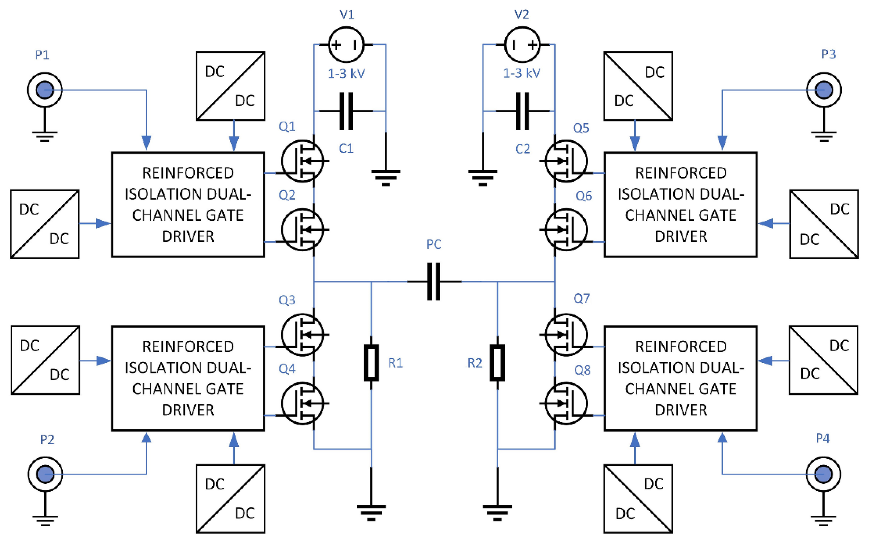
The circuit diagram of the developed high voltage driver is given in Figure 2. The driver contains two arms. Each arm includes 4 transistor switches (Q1–Q4 and Q5–Q8, respectively), forming the symmetric high voltage driver circuit called H-bridge. The output of the H-bridge is loaded by the Pockels cell.
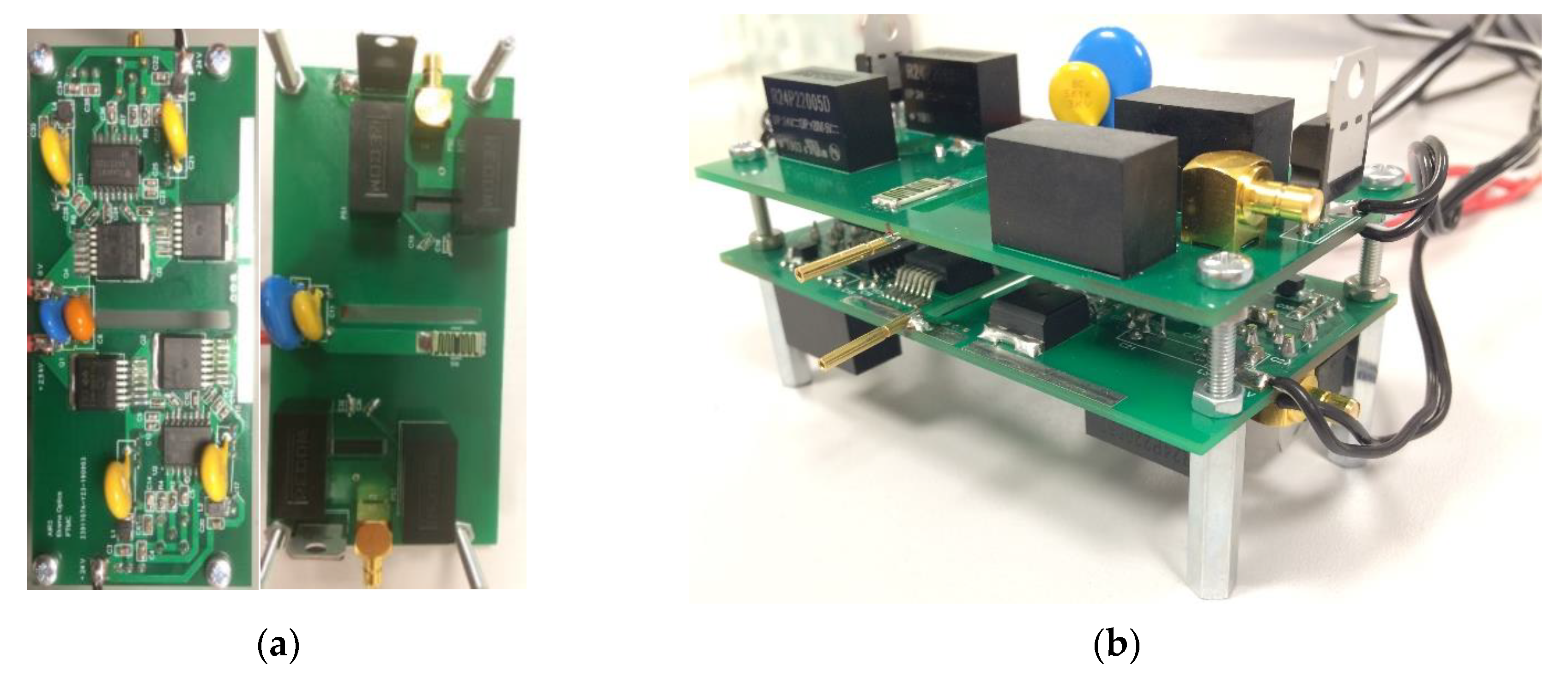
The Silicon Carbide (SiC) MOSFETs were used for the realization of switches of the high voltage driver. The SiC MOSFETs, due to a smaller chip, are characterized by lower parasitic capacitances, therefore, they provide higher dV/dt and dI/dt [28,29], i.e., they allow us to achieve better dynamic characteristics and, as a consequence, allow us to generate HV pulses with a shorter transition time compared to ordinary high voltage drivers based on Silicon (Si) MOSFETs [30]. Additionally, SiC MOSFETs are characterized by higher breakdown voltage and lower on-state resistance when compared to Si MOSFETs [31]. Every switch consists of two transistors connected in series. Series connection of the MOSFETs is used to share voltage in high-voltage applications [32,33]. In our case, the breakdown voltage of every used SiC MOSFET was 1.7 kV. The high voltage driver is able to generate high voltage pulses of up to 3 kV amplitude with a rising edge duration of 7.6 ns. Photos of the developed high voltage driver are presented in Figure 3.
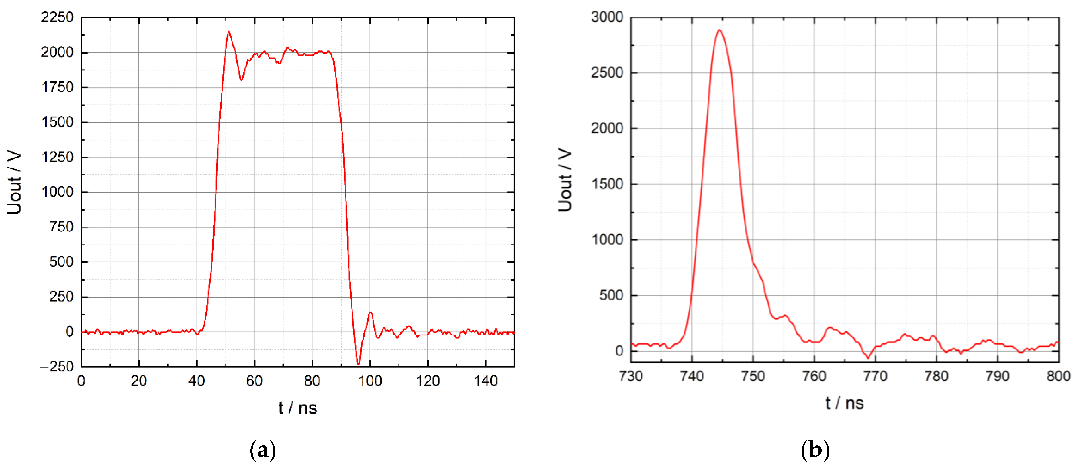
The transistors of H-bridge Q1–Q8 are controlled using reinforced isolation dual-channel gate drivers, which provide galvanic decoupling between the H-bridge and the controller. These gate drivers guarantee a 6 ns pulse transition. To avoid shoot-through of switch transistors in the arm of H-bridge, the delay of the control pulse that opens the switch of the arm (dead-time) has to be introduced. It was experimentally determined that the shortest dead-time which guarantees safe operation of switch transistors is 45 ns. Control inputs of the gate drivers are connected to P1–P4 connectors (SMB type) and 50 Ω impedance matching circuit. Two isolated dc/dc power supplies are used for the supply of every gate driver. Resistors R1 and R2 (Figure 2) are used to provide high impedance path for slow discharge of the Pockels cell if no high voltage is applied. The shortest possible high voltage pulses which can be generated by one of the high voltage driver arms and by the whole high voltage driver are presented in Figure 4. Durations of these pulses are 45 ns and 10 ns, respectively.
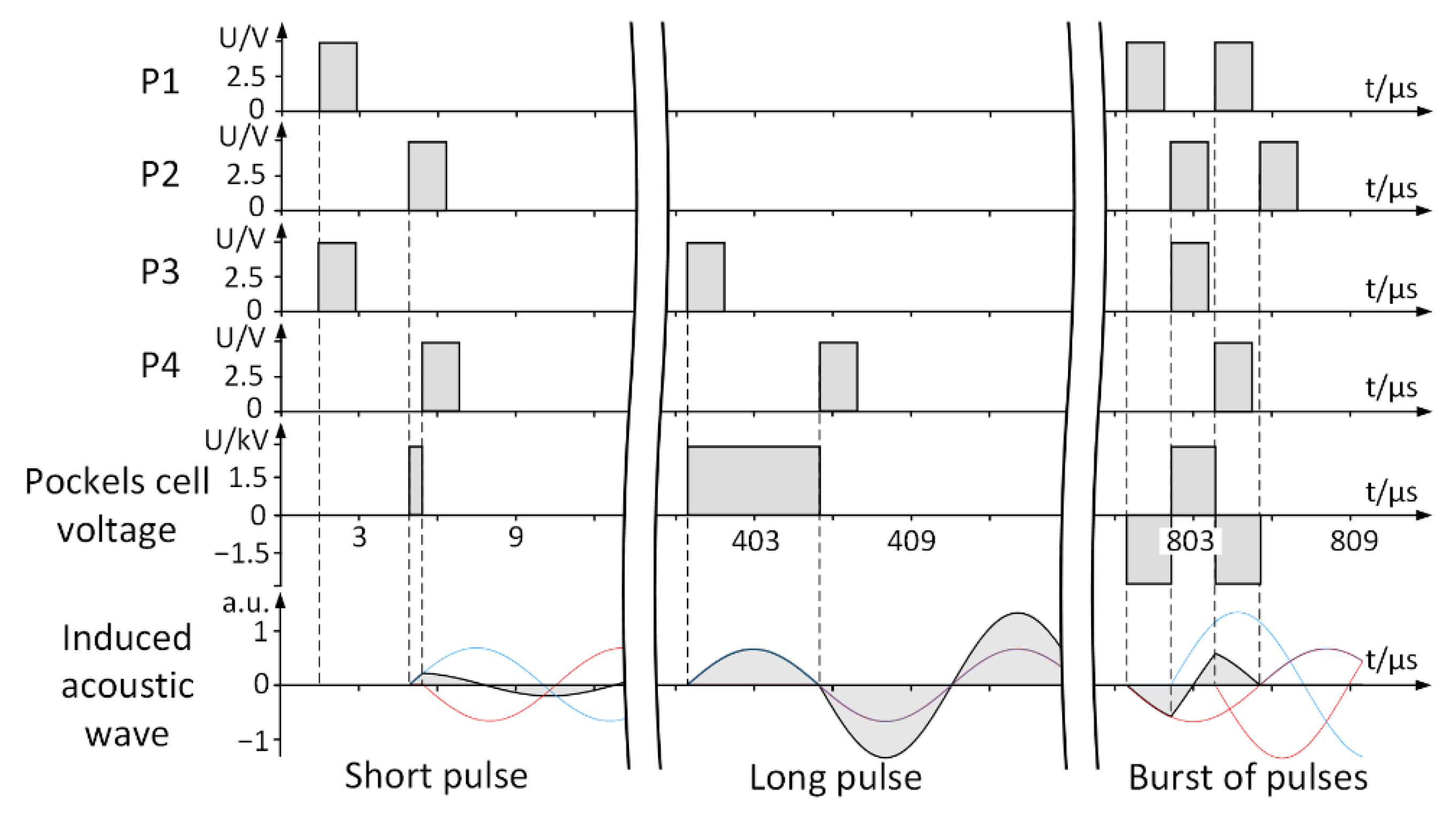
Timing diagrams of the high voltage driver used for the formation of short high voltage pulses and burst of the pulses are presented in Figure 5. Symmetrical positive and negative high voltage pulses can be formed using the H-bridge configuration of the high voltage driver. In the Pockels cell low frequency acoustic waves are generated when transition of voltage occurs. Initial phase of acoustic wave is voltage polarity dependent. Using developed high voltage driver, burst of pulses can be arranged to minimize induced low frequency acoustic waves.

3. Experimental Investigation of Active Piezoelectric Ringing Suppression

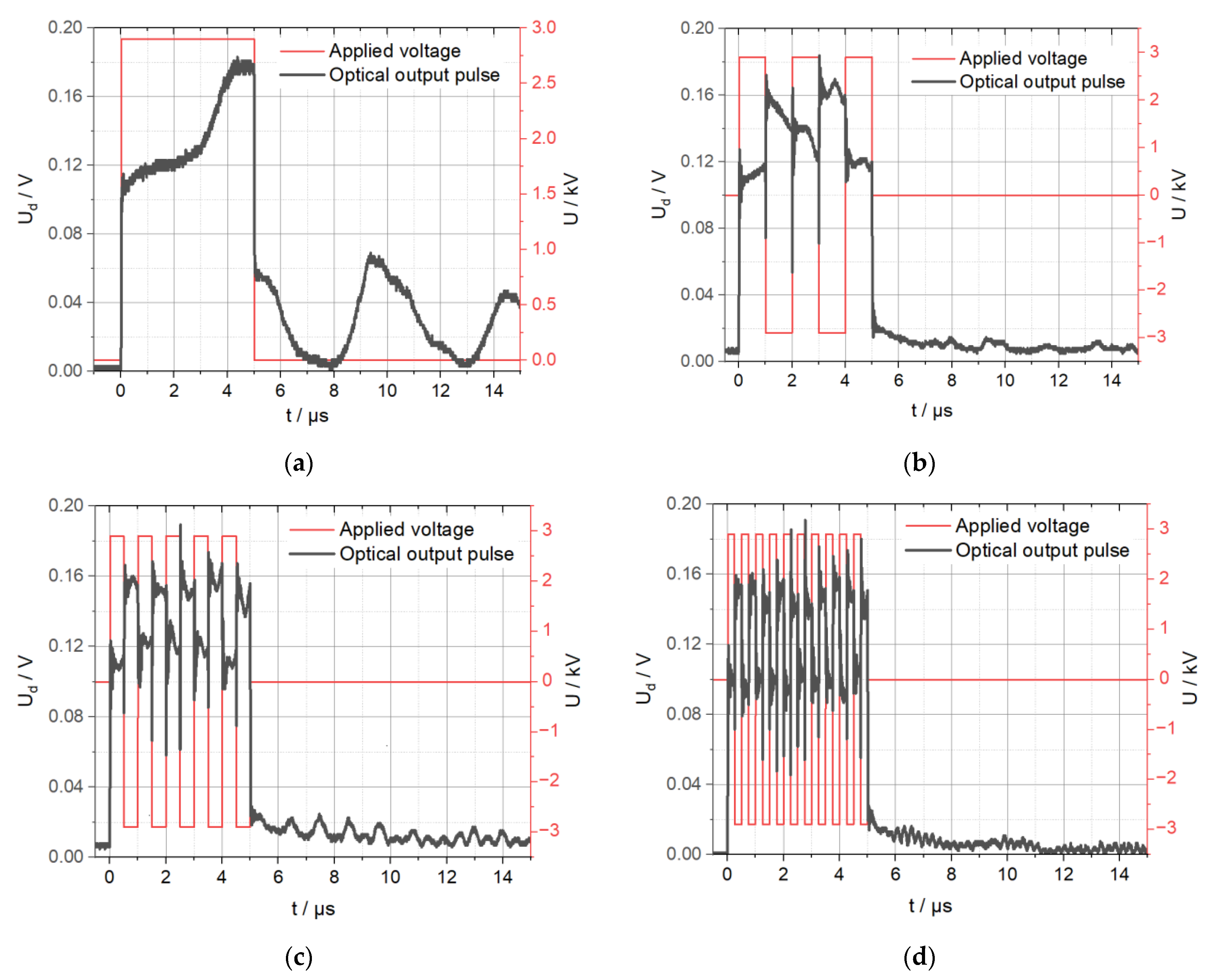
A deuterated potassium dihydrogen phosphate (DKDP) Pockels cell crystal with dimensions of 12 mm aperture and 24 mm length was used for the experiment in a setup equivalent to the one shown in Figure 1a. Experiment was performed using continuous wave laser for observation of dynamic processes. Experimentally determined frequency of acoustic wave caused by the piezoelectric ringing in the analysed DKDP Pockels cell was 100 kHz. A single high voltage pulse with the duration of 5 µs, which is equal to half period of piezoelectric ringing, was applied to the DKDP Pockels cell in our first experiment. Such a pulse induces reinforced piezoelectric ringing [34]. Optical response of the DKDP Pockels cell is presented in Figure 6a. Distorted shape of the pulse that follows after the rising edge of the pulse shows that the acoustic wave is generated inside the DKDP crystal. After the falling edge of the pulse, optical intensity does not fall to steady state value, but exhibits pulsations with the amplitude that reaches up to 30% of the peak intensity.
Optical response of the DKDP Pockels cell, when the active piezoelectric ringing suppression is provided by using a burst of short duration pulses, is presented in Figure 6b–d. The value of the intensity during the burst varies along with the burst pulses. The pulsations of the intensity after the burst of pulses are cancelled when the duration of burst pulses is 1 μs. When the duration of burst pulses is 0.5 μs, some pulsations of the intensity are present; however, their amplitude is about five times lower compared when a single continuous high voltage pulse is applied to the Pockels cell (Figure 6a).
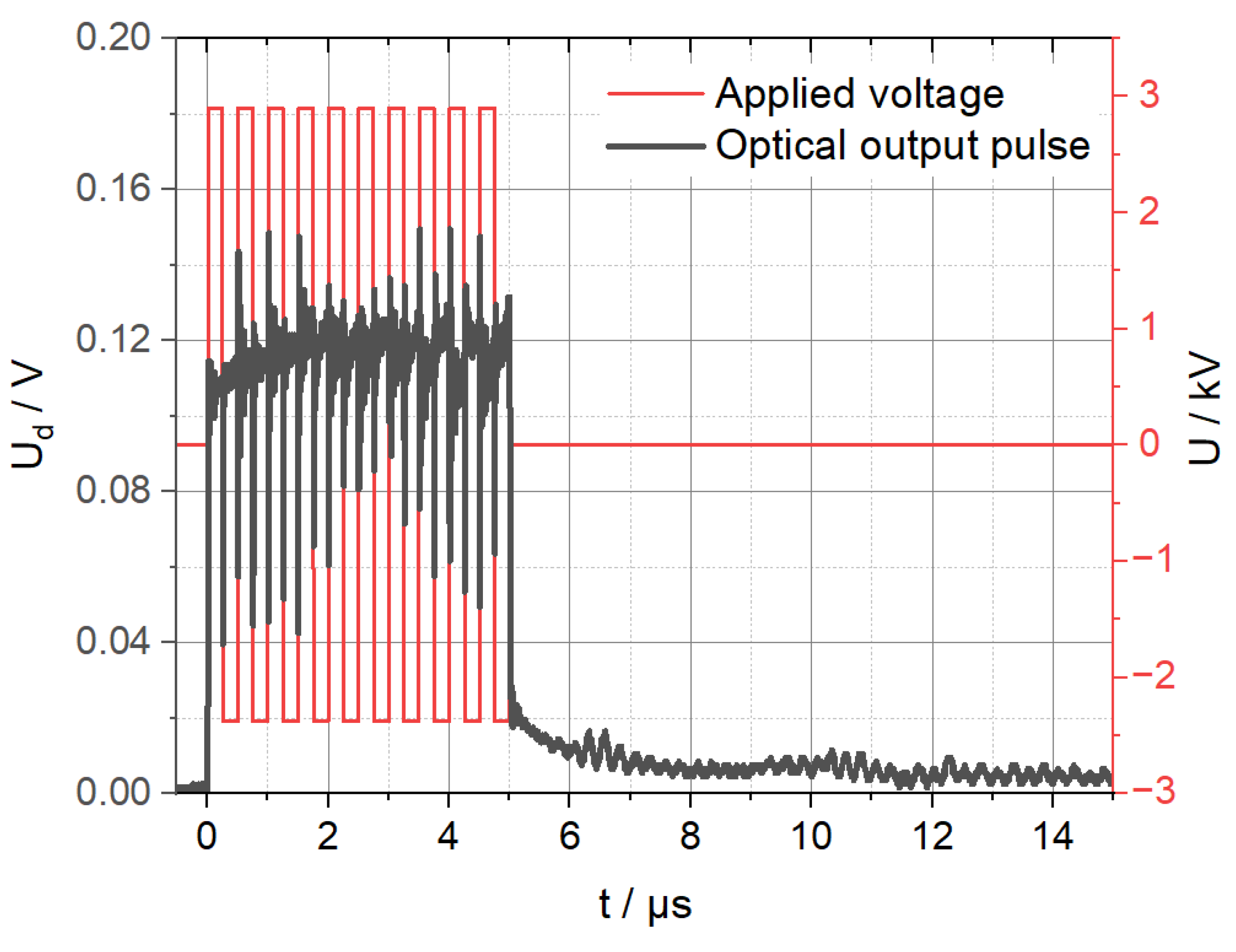
We observed that asymmetry of optical response appears when a burst of short duration pulses is applied. This is illustrated in Figure 6d when pulse duration is 250 ns. Note that odd and even pulses are of the same amplitude but opposite polarity (Figure 5). Two cases were investigated: when the amplitude of high voltage pulses in the burst was the same, and when the amplitude of even pulses was lower than the amplitude of odd pulses. The results show that the deviation of intensity during the burst can be reduced by decreasing the amplitude of even voltage pulses. The best result was achieved when the amplitude of even pulses was reduced by 18% compared to amplitude of odd pulses (Figure 7). The deviation of the intensity during the burst decreases up to three times in such a case. Different amplitudes of even and odd high voltage pulses were achieved by using supply sources V1 and V2 of the different arms of H-bridge (Figure 2) with different voltages.
DKDP Pockels cell optical responses presented in Figure 6 and Figure 7 show significant reduction of the piezoelectric ringing impact on the contrast of the Pockels cell when the proposed active piezoelectric ringing suppression method is applied.
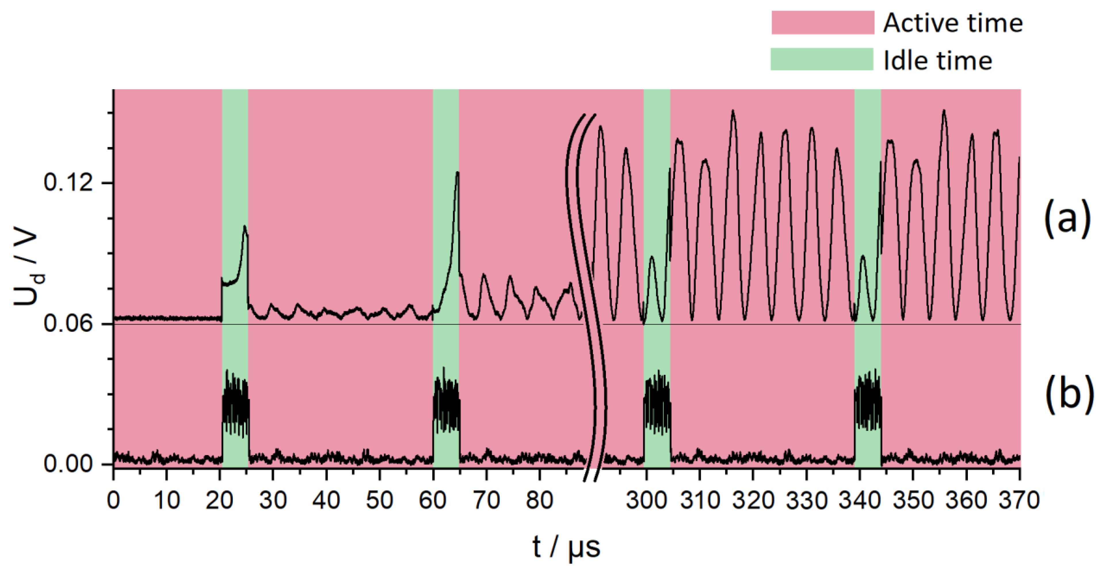
In the next experiment, periodic high voltage high frequency pulses were applied to the DKDP Pockels cell investigating operation in intracavity and extracavity modes (Figure 1). Acoustic waves caused by periodic high frequency pulses have no time to naturally dissipate and increase with each new pulse. Results presented in Figure 8 show the case when high voltage pulses of 5 µs duration and 25 kHz frequency are applied to the DKDP Pockels cell. When no active piezoelectric ringing suppression is used, impact of the piezoelectric ringing on the beam intensity increases over time (Figure 8a). After multiple pulses, maximal acoustic wave amplitude is reached (resonance occurs). On the other hand, application of the proposed active piezoelectric ringing suppression method based on the burst of short duration pulses allows us to achieve stable non-resonant operation of the Pockels cell. This was proven by the investigation, which was performed for the burst that contains 13 pulses of 0.384 µs duration (Figure 8b).
Results presented in Figure 9 display the optical response of the DKDP Pockels cell when 1 µs duration periodic high voltage pulses with 166 kHz frequency are applied. Implementing a burst of high voltage pulses which contains just three pulses of 0.33 µs instead of continuous pulses can reduce the amplitude of the piezoelectric ringing in the active time window up to five times. In this experiment, variations of the intensity during the burst of pulses have been compensated by adjusting the voltage of supply sources V1 and V2 as shown in Figure 2.
Investigation results show that the proposed active piezoelectric ringing suppression method for DKDP Pockels cells can be implemented in the intracavity as well as extracavity applications of lasers.

4. Discussion

The developed high voltage Pockels cells driver based on silicon carbide MOSFET transistors is capable of generating short pulses with duration of tens of nanoseconds, with 3 kV amplitude and 7.6 ns rising edge duration. It allows to implement the proposed active piezoelectric ringing suppression in the Pockels cell crystals using a burst of short high voltage pulses, instead of one long duration continuous pulse.
The experiment shows that when a Pockels cell based on DKDP crystal is controlled using a 5 µs continuous high voltage pulse, the optical intensity of the probing laser beam does not reach the same value as when it is in the steady state. Instead, it exhibits pulsations with the amplitude that reaches up to 30% of the peak intensity due to piezoelectric ringing. The application of a burst of five pulses with 1 μs duration allows us to cancel the pulsations of the intensity after the burst ends. When the duration of burst pulses is 0.5 μs, some intensity pulsations are present; however, the amplitude of pulsations is about five times lower compared to the case when a single continuous high voltage pulse is used.
The difference in transmittance of a laser beam when a burst consists of symmetrical electric pulses of positive and negative polarity can be decreased by reducing the amplitude of even high voltage pulses of the burst. The best result was achieved when the amplitude of even voltage pulses was reduced by 18% as compared to odd pulses. The deviation of the intensity during the burst decreases up to three times in such a case. Similar results were obtained at different frequencies and a different number of pulses in the burst. However, the price for the compensation of the intensity pulsations in the active phase is high-frequency modulation of the intensity in the idle phase.
New possibilities of high voltage switching using modern components provided by the semiconductor industry open new perspectives to develop original circuits, and, as a result, new methods to deal with earlier unsolvable problems. The problem we address in this paper is piezoelectric ringing of the crystals used in Pockels cells. With drivers capable of changing voltage and its polarity at much higher frequencies as is necessary for optical pulse control, we achieved significant reduction of distortions caused by piezoelectric effect and maintained basic functionality. The method is ready to use for applications outside of the laser cavity and shows good potential even for applications inside the cavity, where electric pulse formation and control should be very precise.

Author Contributions

Conceptualization, G.S., A.B., and G.T.; methodology, G.S. and G.T.; software, G.S.; validation, G.S., A.B., and G.T.; formal analysis, G.S, A.B., and G.T.; investigation, G.S.; resources, G.S.; data curation, G.S.; writing—original draft preparation, G.S.; writing—review and editing, G.S., A.B., and G.T.; visualization, G.S and G.T.; supervision, A.B.; project administration, A.B.; funding acquisition, G.S. and A.B. All authors have read and agreed to the published version of the manuscript.

Funding

This research received no external funding.

Institutional Review Board Statement

Not applicable.

Informed Consent Statement

Not applicable.

Data Availability Statement

Not applicable.

Acknowledgments

This work was supported by EKSMA Optics, Ltd. and state research institute Center for Physical Sciences and Technology.

Conflicts of Interest

The authors declare no conflict of interest.

References

  1. Yu, T.; Gao, F.; Zhang, X.; Xiong, B.; Yuan, X. Bidirectional Ring Amplifier with Twin Pulses for High-Power Lasers. Opt. Express OE 2018, 26, 15300–15307. [Google Scholar] [CrossRef]
  2. Rezvani, S.A.; Suzuki, M.; Malevich, P.; Livache, C.; de Montgolfier, J.V.; Nomura, Y.; Tsurumachi, N.; Baltuška, A.; Fuji, T. Millijoule Femtosecond Pulses at 1937 Nm from a Diode-Pumped Ring Cavity Tm:YAP Regenerative Amplifier. Opt. Express OE 2018, 26, 29460–29470. [Google Scholar] [CrossRef]
  3. Fattahi, H.; Alismail, A.; Wang, H.; Brons, J.; Pronin, O.; Buberl, T.; Vámos, L.; Arisholm, G.; Azzeer, A.M.; Krausz, F. High-Power, 1-Ps, All-Yb:YAG Thin-Disk Regenerative Amplifier. Opt. Lett. 2016, 41, 1126–1129. [Google Scholar] [CrossRef] [PubMed]
  4. Giesberts, M.; Fitzau, O.; Hoffmann, H.-D.; Lange, R.; Bachert, C.; Krause, V. Directly Q-Switched High Power Resonator Based on XLMA-Fibers. In Proceedings of the Fiber Lasers XV: Technology and Systems; International Society for Optics and Photonics, San Francisco, CA, USA, 29 January–1 February 2018; Volume 10512, p. 1051218. [Google Scholar]
  5. Römer, G.R.B.E.; Bechtold, P. Electro-Optic and Acousto-Optic Laser Beam Scanners. Phys. Procedia 2014, 56, 29–39. [Google Scholar] [CrossRef] [Green Version]
  6. Sun, Z.; Martinez, A.; Wang, F. Optical Modulators with 2D Layered Materials. Nat. Photonics 2016, 10, 227–238. [Google Scholar] [CrossRef] [Green Version]
  7. Munk, A.; Jungbluth, B.; Strotkamp, M.; Hoffmann, H.-D.; Poprawe, R.; Höffner, J. Diode-Pumped Alexandrite Ring Laser for Lidar Applications. In Proceedings of the Solid State Lasers XXV: Technology and Devices, International Society for Optics and Photonics, San Francisco, CA, USA, 16 March 2016; Volume 9726, p. 97260I. [Google Scholar]
  8. Heinrich, D.; Guggemos, M.; Guevara-Bertsch, M.; Hussain, M.I.; Roos, C.F.; Blatt, R. Ultrafast Coherent Excitation of a 40Ca+ Ion. New J. Phys. 2019, 21, 073017. [Google Scholar] [CrossRef]
  9. Liu, K.; Ye, C.R.; Khan, S.; Sorger, V.J. Review and Perspective on Ultrafast Wavelength-Size Electro-Optic Modulators. Laser Photonics Rev. 2015, 9, 172–194. [Google Scholar] [CrossRef]
  10. Svelto, O. Principles of Lasers, 5th ed.; Springer: Berlin/Heidelberg, Germany, 2010; ISBN 978-1-4419-1301-2. [Google Scholar]
  11. Koechner, W. Solid-State Laser Engineering; Springer Series in Optical Sciences, 6th ed.; Springer: Berlin/Heidelberg, Germany, 2006; ISBN 978-0-387-29094-2. [Google Scholar]
  12. Eichler, H.J.; Eichler, J.; Lux, O. Lasers: Basics, Advances and Applications; Springer Series in Optical Sciences; Springer International Publishing: Berlin/Heidelberg, Germany, 2018; ISBN 978-3-319-99893-0. [Google Scholar]
  13. Goldstein, R. Electro-Optic Devices in Review. Lasers Appl. 1986, 5, 67–73. [Google Scholar]
  14. Goldstein, R. Pockels Cell Primer. Laser Focus 1968, 34, 21. [Google Scholar]
  15. Sinkevicius, G.; Vengelis, J.; Banys, J.; Masiulis, L.; Grigonis, R.; Baskys, A.; Sirutkaitis, V.; Domarkas, J. Investigation of Piezoelectric Ringing Effects in Deuterated Potassium Dihydrogen Phosphate Crystals. Opt. Eng. 2020, 59, 1–11. [Google Scholar] [CrossRef]
  16. Vengelis, J.; Sinkevičius, G.; Banys, J.; Masiulis, L.; Grigonis, R.; Domarkas, J.; Sirutkaitis, V. Investigation of Piezoelectric Ringing Effects in Pockels Cells Based on Beta Barium Borate Crystals. Appl. Opt. 2019, 58, 9240–9250. [Google Scholar] [CrossRef]
  17. Takeda, K.; Hoshina, T.; Takeda, H.; Tsurumi, T. Electro-Optic Effect of Lithium Niobate in Piezoelectric Resonance. J. Appl. Phys. 2012, 112, 124105. [Google Scholar] [CrossRef]
  18. Sinkevicius, G.; Baskys, A. Investigation of Piezoelectric Ringing Frequency Response of Beta Barium Borate Crystals. Crystals 2019, 9, 49. [Google Scholar] [CrossRef] [Green Version]
  19. Bergmann, F.; Siebold, M.; Loeser, M.; Röser, F.; Albach, D.; Schramm, U. MHz Repetion Rate Yb:YAG and Yb:CaF2 Regenerative Picosecond Laser Amplifiers with a BBO Pockels Cell. Appl. Sci. 2015, 5, 761–769. [Google Scholar] [CrossRef] [Green Version]
  20. Sinkevicius, G.; Baskys, A. Investigation of Frequency Response of Pockels Cells Based on Beta Barium Borate Crystals. In Proceedings of the 2017 Open Conference of Electrical, Electronic and Information Sciences (eStream), Vilnius, Lithuania, 27 April 2017; pp. 1–4. [Google Scholar]
  21. Yin, X.; Jiang, M.; Sun, Z.; Hui, Y.; Lei, H.; Li, Q. Intrinsic Reduction the Depolarization Loss in Electro-Optical Q-Switched Laser Using a Rectangular KD*P Crystal. Opt. Commun. 2017, 398, 107–111. [Google Scholar] [CrossRef]
  22. Nickel, D.; Stolzenburg, C.; Beyertt, A.; Giesen, A.; Häußermann, J.; Butze, F.; Leitner, M. 200 KHz Electro-Optic Switch for Ultrafast Laser Systems. Rev. Sci. Instrum. 2005, 76, 033111. [Google Scholar] [CrossRef]
  23. Salvestrini, J.P.; Abarkan, M.; Fontana, M.D. Comparative Study of Nonlinear Optical Crystals for Electro-Optic Q-Switching of Laser Resonators. Opt. Mater. 2004, 26, 449–458. [Google Scholar] [CrossRef]
  24. Springer Handbook of Lasers and Optics, 2nd ed.; Träger, F. (Ed.) Springer Handbooks; Springer: Berlin/Heidelberg, Germany, 2012; ISBN 978-3-642-19408-5. [Google Scholar]
  25. Kim, H.; Yu, C.; Jang, S.; Kim, G. Solid-State Pulsed Power Modulator With Fast Rising/Falling Time and High Repetition Rate for Pockels Cell Drivers. IEEE Trans. Ind. Electron. 2019, 66, 4334–4343. [Google Scholar] [CrossRef]
  26. Biryuchinskiy, S.; Melnikov, K.; Melnikov, V. Analysis of an Ultrafast MOSFET Based Pockels Cell Driver. Available online: https://www.scientific.net/AMR.679.53 (accessed on 1 December 2020).
  27. Bishop, A.I.; Barker, P.F. Subnanosecond Pockels Cell Switching Using Avalanche Transistors. Rev. Sci. Instrum. 2006, 77, 044701. [Google Scholar] [CrossRef]
  28. She, X.; Huang, A.Q.; Lucía, Ó.; Ozpineci, B. Review of Silicon Carbide Power Devices and Their Applications. IEEE Trans. Ind. Electron. 2017, 64, 8193–8205. [Google Scholar] [CrossRef]
  29. Li, X.; Zhang, L.; Guo, S.; Lei, Y.; Huang, A.Q.; Zhang, B. Understanding Switching Losses in SiC MOSFET: Toward Lossless Switching. In Proceedings of the 2015 IEEE 3rd Workshop on Wide Bandgap Power Devices and Applications (WiPDA), Blacksburg, VA, USA, 2–4 November 2015; pp. 257–262. [Google Scholar]
  30. Liu, Z.; Cong, L.; Lee, H. Design of On-Chip Gate Drivers With Power-Efficient High-Speed Level Shifting and Dynamic Timing Control for High-Voltage Synchronous Switching Power Converters. IEEE J. Solid State Circuits 2015, 50, 1463–1477. [Google Scholar] [CrossRef]
  31. Physical Properties of Silicon Carbide. In Fundamentals of Silicon Carbide Technology; John Wiley & Sons, Ltd.: Hoboken, NJ, USA, 2014; pp. 11–38. ISBN 978-1-118-31353-4.
  32. Baek, J.W.; Yoo, D.W.; Rim, G.H.; Lai, J.-S. Solid State Marx Generator Using Series-Connected IGBTs. IEEE Trans. Plasma Sci. 2005, 33, 1198–1204. [Google Scholar] [CrossRef]
  33. Ren, Y.; Yang, X.; Qiao, L.; Zhang, F.; Wang, L. A Novel Solid-State DC-Breaker Based on Cascaded SiC MOSFETs. In Proceedings of the 2017 IEEE Applied Power Electronics Conference and Exposition (APEC), Tampa, FL, USA, 26–30 March 2017; pp. 824–828. [Google Scholar]
  34. Samsonas, D.; Petrulionis, D.; Grigaitis, D.; Vengris, M. Influence of the Piezoelectric Ringing on the Polarisation Contrast of the KRTP Pockels Cell in the Modulation Frequency Range up to 10 MHz. In Components and Packaging for Laser Systems VII; International Society for Optics and Photonics: Bellingham, WA, USA, 5 March 2021; Volume 11667, p. 116670G. [Google Scholar]
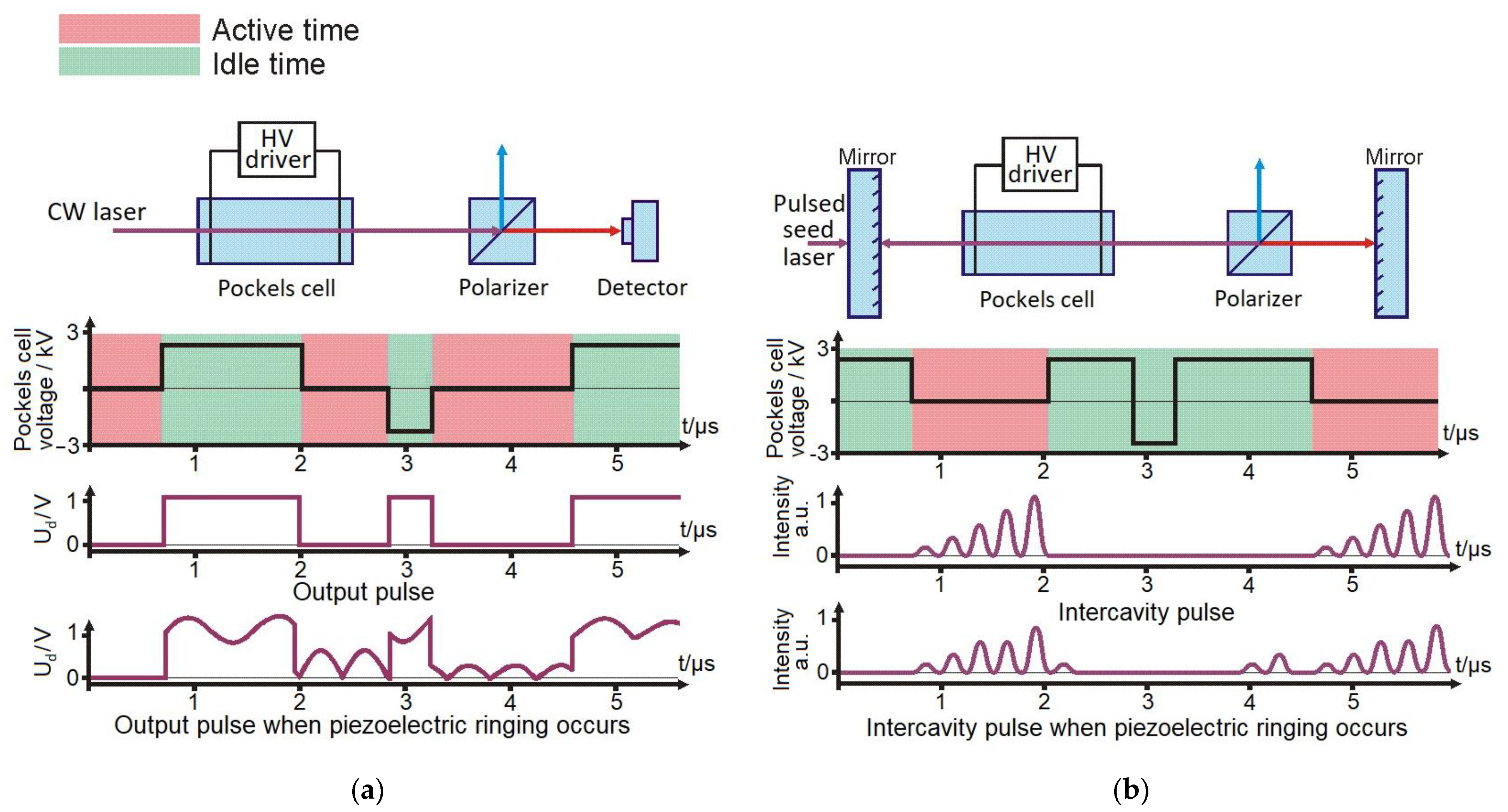
Figure 1. Timing diagram of operation of Pockels cell in: (a) extracavity mode; (b) intracavity mode (Ud is detector output voltage).
Symmetry 13 00677 g001
Figure 2. Circuit diagram of developed high voltage driver.
Symmetry 13 00677 g002
Figure 3. Photo of developed high voltage driver: (a) top and bottom of one arm; (b) the whole high voltage driver.
Symmetry 13 00677 g003
Figure 4. Shortest pulse generated: (a) by one of high voltage driver arms; (b) by whole high voltage driver.
Symmetry 13 00677 g004
Figure 5. Timing diagram of the high voltage driver. Acoustic wave caused by the rising edge of the high voltage pulse is marked in blue, caused by the falling edge—in red and resulting wave—in grey.
Symmetry 13 00677 g005
Figure 6. Optical response of deuterated potassium dihydrogen phosphate (DKDP) Pockels cell: (a) with no active piezoelectric suppression; with active piezoelectric ringing suppression using bursts of (b) 1 μs, (c) 0.5 μs, (d) 0.25 μs pulses.
Symmetry 13 00677 g006
Figure 7. Optical response of the DKDP Pockels cell when active piezoelectric ringing suppression with 250 ns burst pulse width is used. Variations of the intensity during the burst of pulses have been compensated by adjusting the voltage of supply sources.
Symmetry 13 00677 g007
Figure 8. Optical response of the DKDP Pockels cell to high voltage pulses of 25 kHz frequency: (a) when the pulses are continuous with a duration of 5 µs; (b) when 5 µs duration bursts of pulses are applied.
Symmetry 13 00677 g008
Figure 9. Optical response of the DKDP Pockels cell to high voltage pulses of 166 kHz frequency: (a) when the pulses are continuous with a duration of 1 µs; (b) when 1 µs duration bursts of pulses are applied.
Symmetry 13 00677 g009
Publisher’s Note: MDPI stays neutral with regard to jurisdictional claims in published maps and institutional affiliations.