1. Introduction
Milling cutters are widely used in manufacturing due to their capacity to process a large variety of surface shapes, from very simple ones to freeform shapes. Still, a certain type and size of milling cutter must be chosen to fit the specific shape of the surface to be machined. Sometimes special milling cutters have to be designed to fit to the machined profiled surfaces. A particular kind of milling cutters are the modular ones, the so-called gang milling cutters or profiled gang cutters. When it is necessary to cut a part with a certain profile, a solution is to materialize that profile as a generating curve on the milling cutter. However, this might pose some technological problems, both in manufacturing the cutter and sharpening it. To overcome these problems, a solution is to divide the profiled cutter into “slices”, which are easier to be machine, and which are later put together on a central shaft. That is, in fact, a gang milling cutter, a modular cutting tool [
1,
2]. The main drawback of these kinds of tools is that they can be used only for a specific job. Because of their narrow range of applications they are available for, the profiled gang, tool designers rarely focus on this category of cutting tools. However, some patents were issued on this subject [
3,
4,
5,
6,
7]. Some research papers and their findings have been published on the topic in the scientific literature and at conferences. Yet, they point to aspects other than those approached in the present paper. Some of the published works are mentioned here.
The dynamic behaviour of the modular cutting tools was studied. A theoretical study—finite elements analysis—was performed and applied for modular cutting tools to forecast the behaviour of these cutting tools under the action of cutting forces [
8], and experimental research aimed to find out if the cutting performance of the modular cutting tools is influenced by their dynamic flexibility [
9]. In the literature, a computer aided design (CAD) technique for designing profiled gang cutters is presented as an application of using computers in engineering [
10]. High speed machining for modular milling is approached as well: the behaviour of the modular tools under the stress of high acceleration and shocks posed by high speed machining is studied in an experimental research paper [
11]. A generalized tool with elements of modularity is also described. Based on the estimation of the cutting forces, different tools can be modelled on the same tool body due to adjustment facilities of some tool’s elements [
12]. In terms of cooling the cutting area at milling, some studies are presented, regarding the distribution of the heat field when cooling with CO
2 [
13], the using of an internal cooling system [
14], and heat pipe cooling to dissipate the heat from the cutting area [
15]. An external cooling system for milling [
16] able to lead the coolant straight to the cutting area is also presented. This displays the advantage that in fact it is a tool holder that can be coupled with any type of tailed milling cutter, so it has a certain level of universality. In [
17] modularity is studied, but as an application for machine tools, not for cutting tools. Yet, some principles of modularly design can be applied both for machine tools and cutting tools. Some different approaches to the cooling the cutting area can be found in literature as well. The authors of [
18] investigated the way the cooling strategy can influence some aspects of cutting technologies, like power consumption or the roughness of the surface machined by the end milling of a certain material. A strategy of optimizing the cooling performance by using three coolant jets is presented in [
19]. One jet has a stable orientation, while the orientation of the other two can be adjusted to fit better to the specifics of machining. Alternative coolants are investigated to reduce the impact of the cutting processes on the environment. The authors of [
20] proposed a new metalworking fluid based on biological agent, whose main components were two yeast strains. A relative new technique, minimum quantity lubrication (MQL) is more and more present in literature. Three different approaches to it are presented in [
21,
22,
23].
The last seven cited works have a common feature—they investigate narrow domains which need special infrastructure or materials. In contrast with that, the present proposal targets a solution with a certain level of universality in terms of the means of cooling the cutting area. This needs only a machine tool equipped with an inner cooling system, which is something common nowadays.
The authors of this paper are concerned with the problem of profiled gang cutters and modular milling cutters, having published their own results in papers [
1,
2,
24,
25], which resulted in two patent proposals [
26,
27]. The novelty of the modular milling cutter presented here consists in some original and innovative key elements: a new shape of the shaft, which offers a much higher capacity to transmit torque than the classic shafts, a new cooling system that distributes coolant on the entire circumference of the cutting tool, and in the integrated manner of approaching the subject: modularity, symmetry, torque transmission, and cooling system.
2. Materials and Methods
A CAD model of original modular milling cutting tool is presented in this paper. It is the outcome obtained as a result of combining the knowledge available in the literature, the personal experience of the authors, and creative and innovative technical thinking. Based on a critical analysis of the existing milling cutting tools, a new, technically enhanced solution was issued. This is a new concept of complex cutting tool. It was carefully designed to simultaneously meet the requirements of a performant cutting tool, of versatility given by the modular concept, and those imposed for manufacturing it. The principles of design for manufacturing (DFM) were obeyed to create a product that can be manufactured easily, effectively, and with low costs of production. The product was modelled in a CAD environment. The assembly was checked to ensure that it is free of interferences between the adjacent parts. Several variants of the products obtained through assembling the same set of elements in different ways were studied. At the same time, special attention was paid to the symmetry of the complex as well, as a necessary condition for a rotating object. When needed, different variants of the constructive solutions of the parts were analysed to find the best solution that could lead to a good functioning of the modular complex on the one hand, and to the product itself being easy to manufacture, on the other hand.
The main drawbacks emphasized when analysing the existing modular milling cutters are as follows:
They are usable only for a specific job because of their unchangeable shape;
The difficulty of aligning the cutting elements to obtain the correct desired profile;
The lack of coolant needed to properly cool the cutting area and the cutting tool.
This new concept of modular milling cutting tool removes all the above presented disadvantages.
3. Results
The main results of the research are the concept and the model of a new modular milling cutter with an enhanced self-cooling system, and a patent proposal [
27]. The mentioned patent proposal is the base of the modular cutting tool presented here.
Figure 1 displays the model of the modular tool mounted in the tool holder [
27], and in
Figure 2 the exploded model is presented so that its elements can be identified and their roles explained [
27].
The special screw (1) is the part that keeps all the other elements together, being screwed into the tool holder. The front side elementary milling cutter (2), and the elementary regular milling cutters (3) are assembled by means of their special profiled reaming on the shaft (8). This, in turn, has in cross section the conjugated profile to the cutters’ reaming. The distributor (7) leads the coolant provided by the inner cooling system of the machine tool to the nozzles (6). The nozzles drive the coolant to the side surface of the modular tool and to the cutting area. The distributor is fixed on the shaft by means of the threaded pins (6).
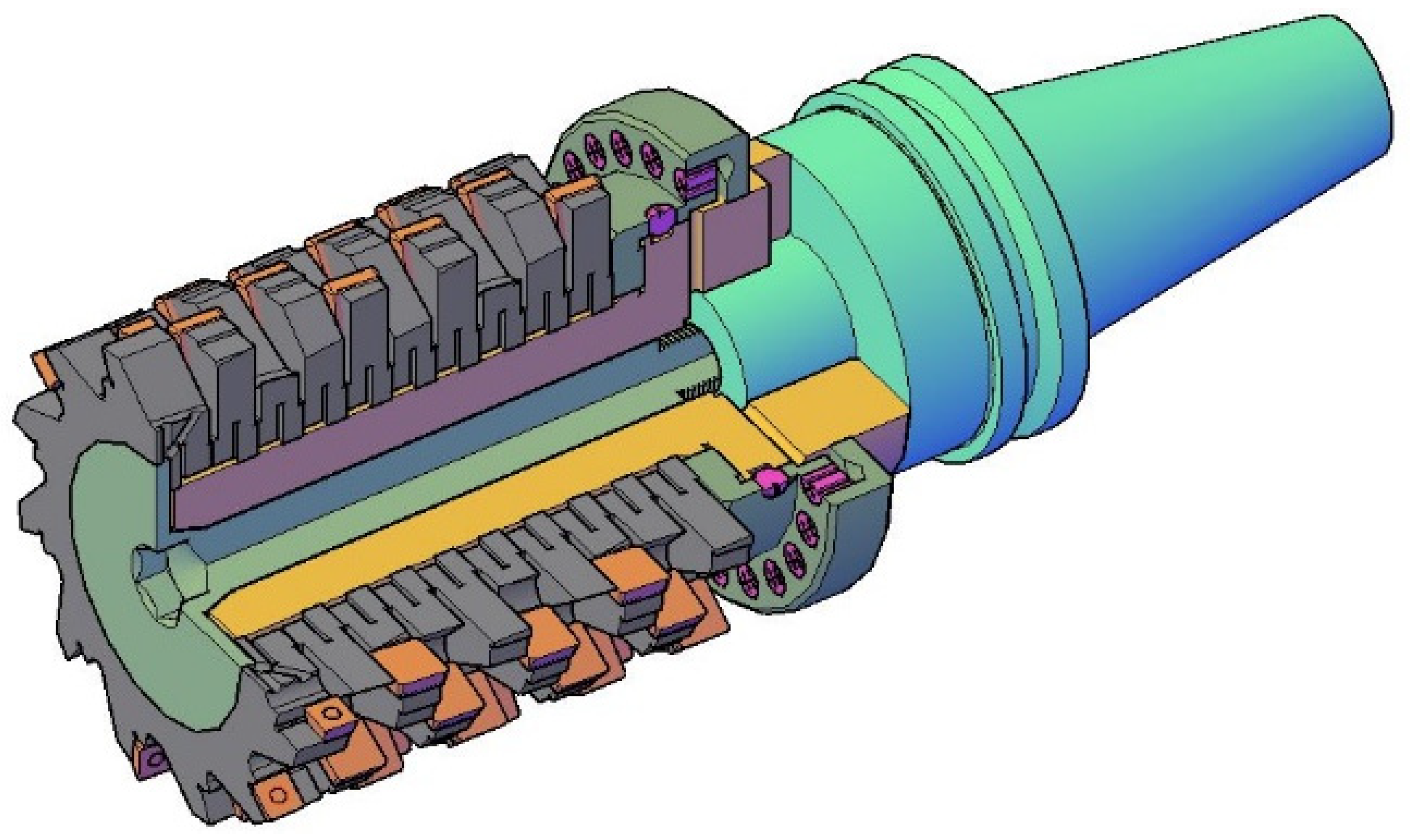
3.1. Grooved Shaft
The shaft is a grooved one, having a particular shaped cross section. The shape is obtained simply cutting some longitudinal grooves onto the cylindrical surface of the shaft. The even (symmetrical) distribution on the periphery of the shaft is determined by the profile of the milling cutters’ holes, which is more sophisticated. In
Figure 3 it can be seen how the two parts—the shaft and the milling cutters—are conjugated. The correct alignment of the coupled parts is given by the outer diameter of the shaft that forms a precise fit with the smooth hole of the milling cutters (described in the next subsection) [
27].
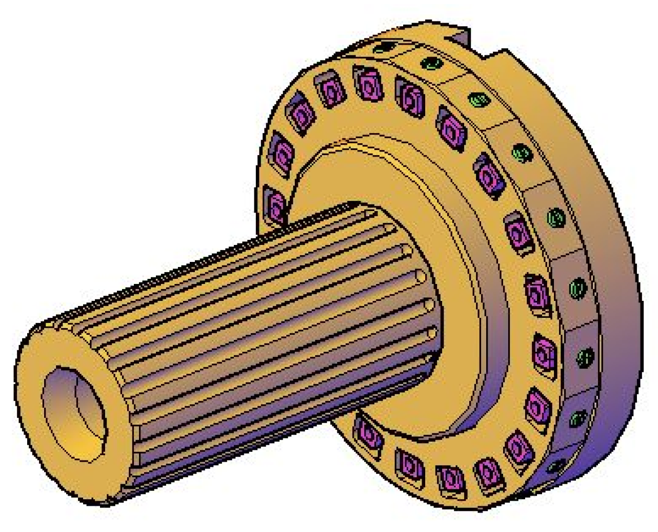
The longitudinal grooves on the shaft shown in
Figure 4 are easily manufactured by a ball nose milling cutter [
27]. On the front end of the shaft are some radial grooves that are constrained together with the flange of the central screw, forcing the coolant to flow to the front cutting edges of the modular milling cutter. The coolant arrives at the front end of the shaft through the gap between the screw and the hole of the shaft. The conical surface of the shaft and of the screw ensure the correct centring of the two parts. At the rear end of the shaft are bored some radial holes that lead the coolant to the distributor. On the cylindrical outer surface of the shaft’s collar there is a ring groove used to assemble the distributor on the shaft by means of some threaded pins.
In the first variant of the design, the shaft and distributor formed a single part, as shown in
Figure 5 [
27]. This part can be considered too complex, as it might pose manufacturability difficulties, so an assembled solution was finally adopted. This complex shaft shape also had the disadvantage of the nontechnological shapes of the nozzle and the pockets they are mounted in. The way they had to be assembled was a difficult one as well.
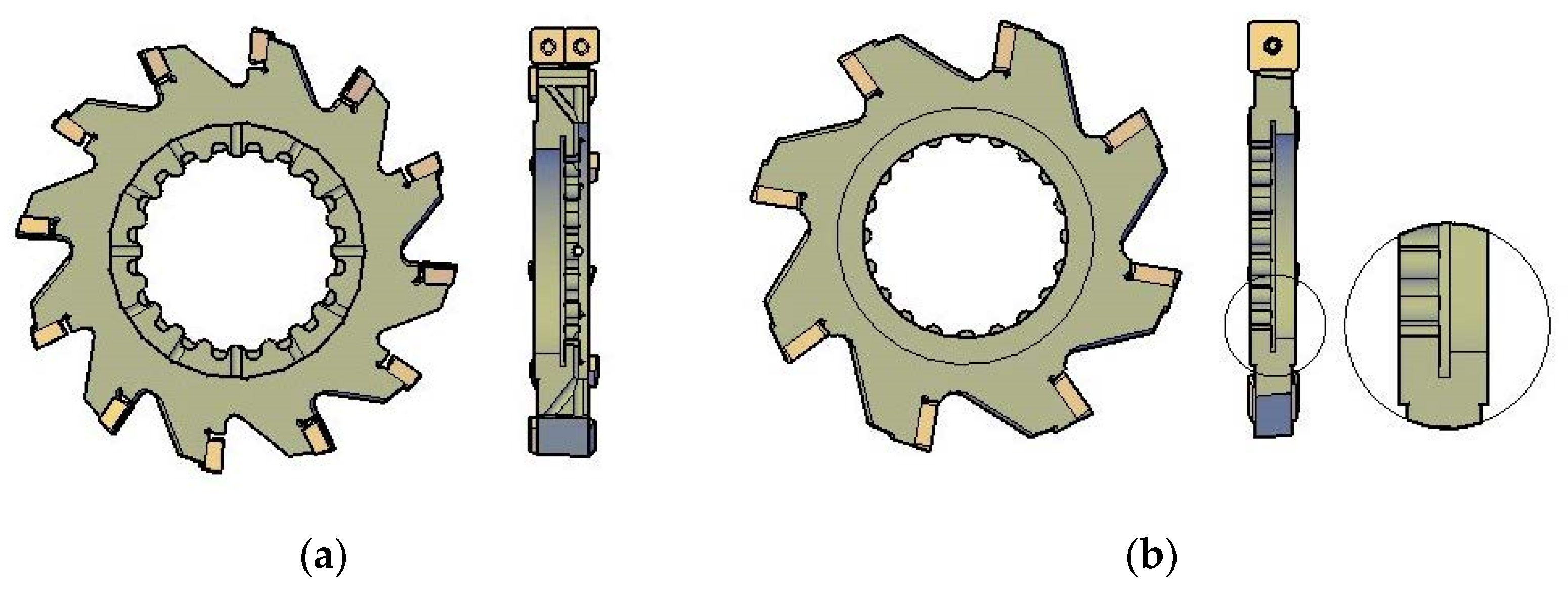
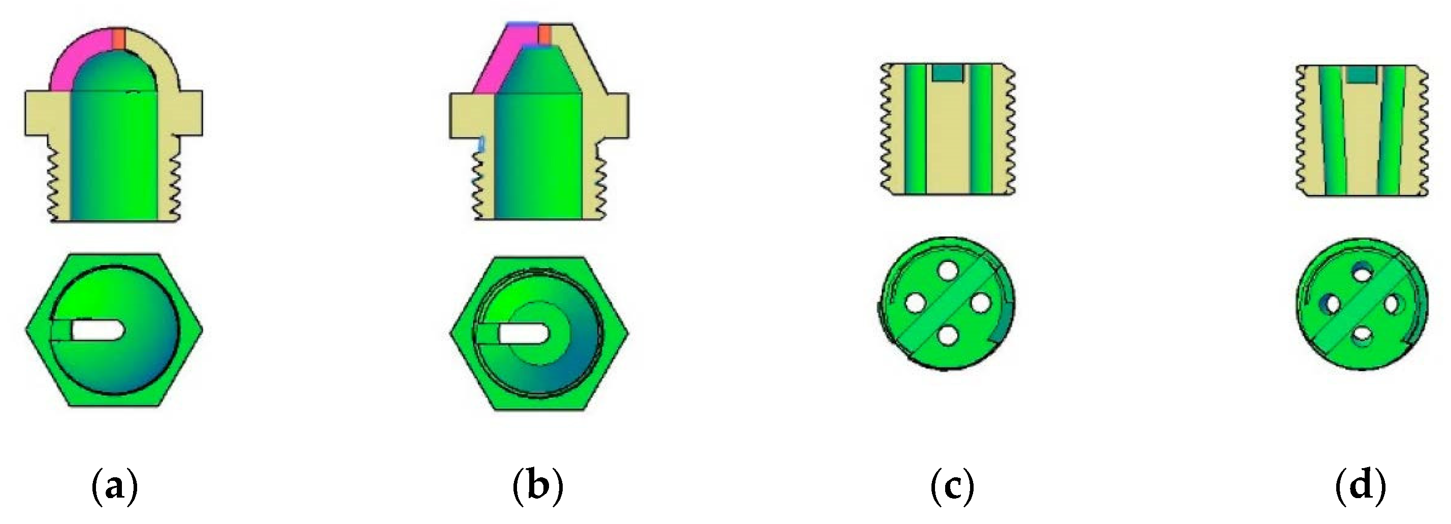
3.2. Elementary Milling Cutters
Several types of elementary milling cutters can be assembled to form the modular milling cutter. The front one, shown in
Figure 6a, has the appropriate geometry to be able to act as a front cutter and to receive the coolant from its inner side. No matter the type of elementary milling cutter, the geometry of the reaming is important. This is shown in the detail of
Figure 6b. The reaming has two distinctive sections, as can be seen in the cross sections of the milling cutters—
Figure 6a,b. One section is profiled and one smoothed. The profiled section, conjugated to the shaft profile, fulfils the task of transmitting the torque. The smoothed section ensures the correct alignment and the centring of the elementary milling cutter, since its diameter and the outer diameter of the shaft form a precise fit (H7/H6). The two sections of the reaming are separated by a technological groove.
Symmetry is essential to find the optimal profile of the reaming. The profile must have certain radii of the internal and external arcs, the value of the internal radius must have a normalized value, and the two adjacent arcs have to be filleted. The restrictions mentioned are imposed for technological reasons, so the profile can be easily programmed and machined using a common cutting tool (end mill for the reaming, and ball nose mill for the shaft—preferably, the two milling cutters should have the same diameter). Furthermore, all these restrictions must be fulfilled respecting the condition that the number of pitches of the profile must be an even integer. It is recommended that the angular pitch of the profile be a divisor of 90° to be able to respect the symmetry, and to obtain a repeated pattern of the elementary milling cutters along the axis of the tool. The smaller the angular pitch is, the more versatile the modular milling cutter is, and the more combinations of elementary cutters are available.
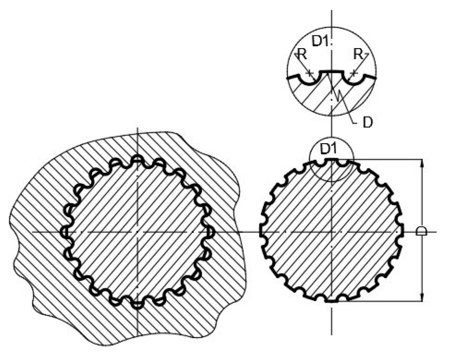
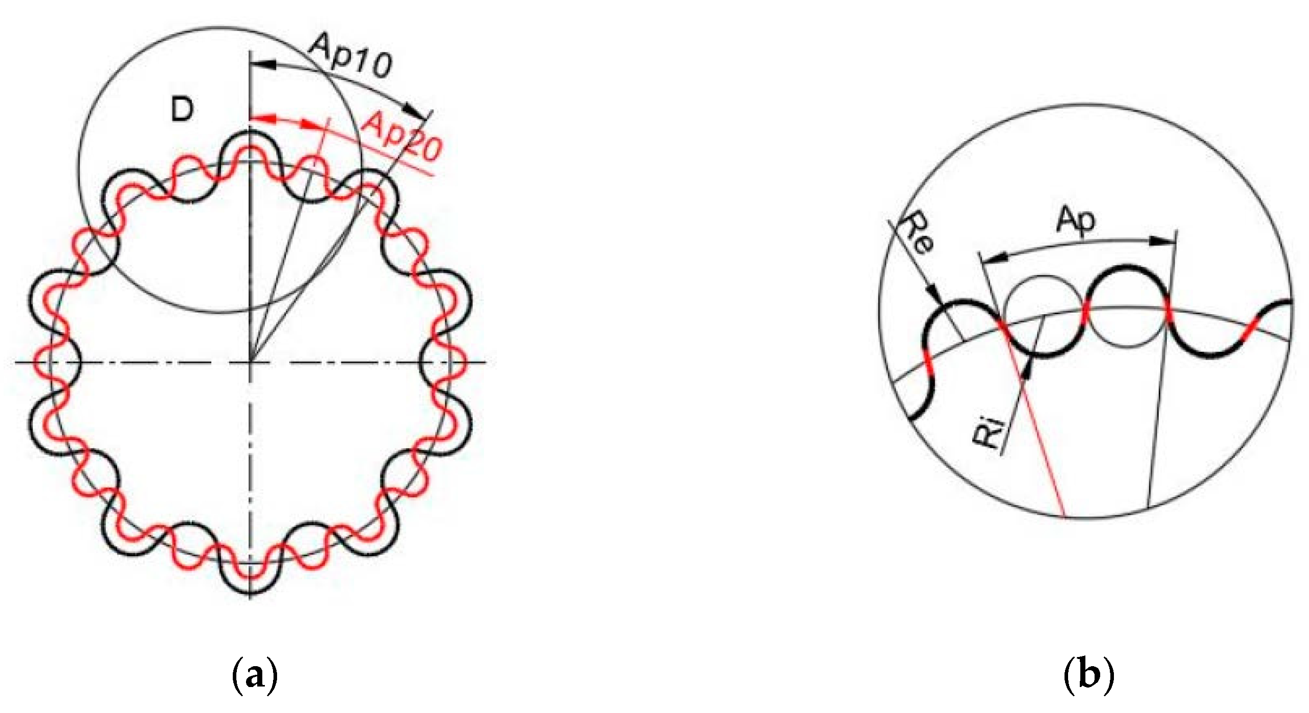
3.3. Determining the Profile of the Elementary Cutter Reaming
To determine the inner profile of the elementary cutter’s hole are better used the facilities of a CAD environment. In this case, the center of the arc with
Ri radius (equal to that of the ball nose milling cutter used to machine the grooves on the shaft) should be placed on the diameter of the shaft for an easy adjustment of the tool when manufacturing the shaft. However, this leads to the
Ri arc having an opening smaller than 180°. If the outer arc needs to have the same radius,
Ri, as the inner one, they do not fill an angular pitch of the profile, and they need to be connected by their common tangent (emphasized in red in
Figure 7b. All the stated work correctly in terms of their geometry, but they pose technological problems: the profile so described cannot be machined because of some undercuts which produce interference between the shaft and cutter, so they cannot be assembled.
In these conditions, another solution must be adopted. It is a little more difficult in terms of the tools’ adjustment when machining the shaft, but eliminates the reasons for the undercut while manufacturing the parts, ensuring an assembly free of interferences. Again, the facilities offered by the CAD environment are helpful. The premises of drawing the profile are as follows:
The profile section of shaft groove is an arc with an opening of 180°; this requires that its centre is inside of the shaft diameter; the exact position of this arc must be determined analytically;
The tangent point of the inner and outer arc on the cutter hole profile must be exactly on the circumference of shaft,
R in
Figure 8b. Because of that, the outer arc of the profile will have not the same radius like the inner one. This is not important, because it does not count for the correct assembly of the shaft and elementary cutter; furthermore, this radius does not depend on the cutting tool diameter, as happens when machining the groove on the shaft;
The outer arc will have a bigger opening than 180°, and its radius will be determined by either analytical or by CAD construction;
The angular pitch is determined by the number of grooves on the shaft.
The necessary mathematical equations are presented below:
where:
Ap = angular pitch of the profile;
z = number of grooves on the shaft, and of teeth of the profile;
where:
A = the included angle on the profile of the hole covered by the diameter of inner arc—see
Figure 8b;
Ri = radius of the profile inner arc;
R = shaft radius;
where:
Yc = the
Y coordinate of the inner arc center on profile. The
X coordinate of the same center is 0 if we assume that the origin of the coordinate system is in the center of the profile.
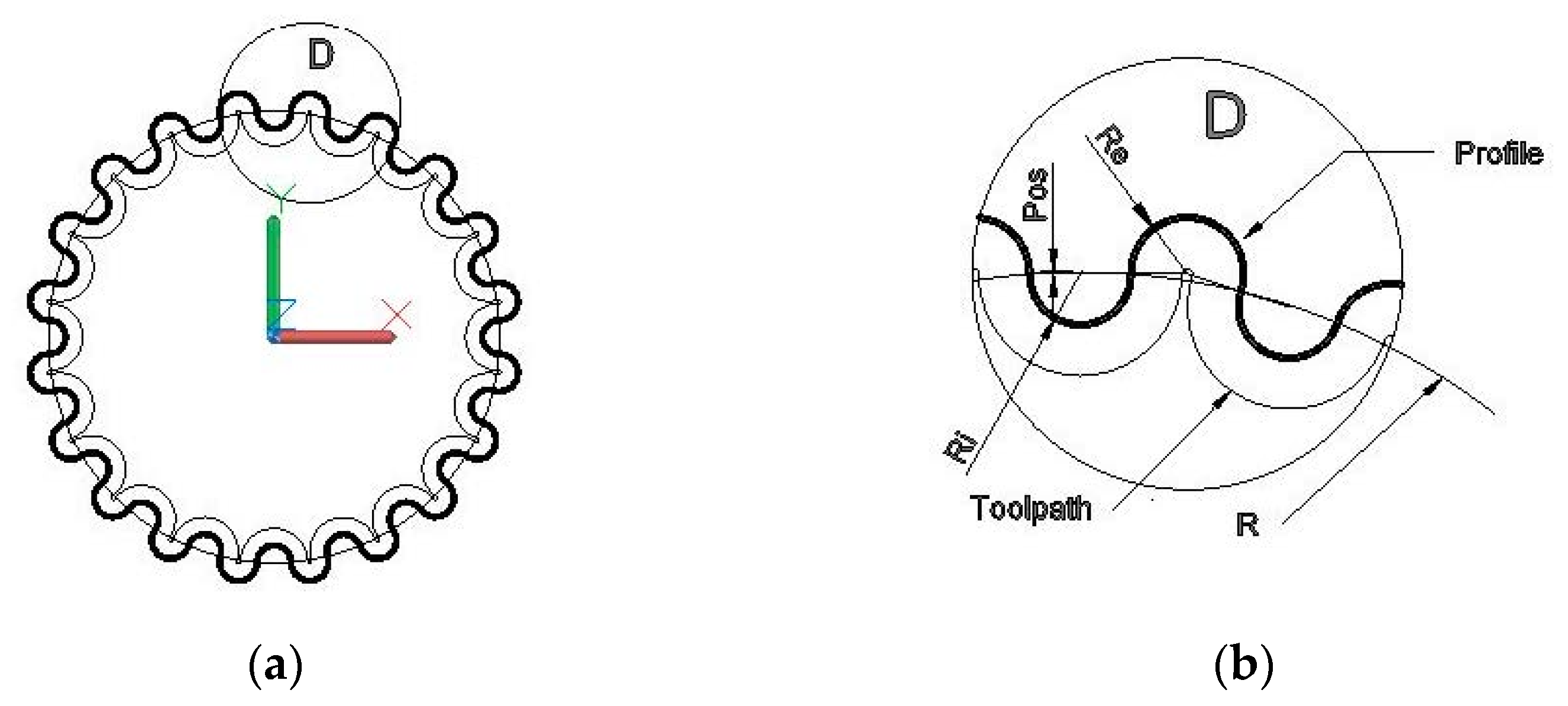
The center of the outer arc (
Re) of the profile is also determined using the CAD environment. In
Figure 6b,
Pos indicates the center position of circle
Ri inside the shaft diameter. In
Table 1 are presented the data determined for different grooved assemblies. The symbols in the heading of
Table 1 represent:
D = shaft diameter;
z = number of grooves (teeth on the inner cutter profile);
R = radius of cross section of the groove on the shaft;
Ri = radius of the inner arc on the profile, as input data;
Ap = angular pitch of the profile;
Re = radius of the outer arc on profile;
Pos = position of center of
Ri inside the diameter of shaft, as output data.
Ap,
Re and
Pos are collected from the CAD system.
3.4. Determination of Capacity to Transmit Torque of the Grooved Shaft
When thinking about the capacity to transmit the torque of the new grooved shaft, a comparison to the classical key and keyway assembling might be interesting. The capacity to transmit the torque is limited by the shear stress the key is subjected to. The torque transmitted depends on the tangential force and the diameter it is applied on. Since the diameter of the shaft is the same in the two solutions compared, it follows that the comparison must be applied to the capable tangential (shearing) force. Furthermore, if we accept that the material the shaft is made of has a similar admissible shear stress as the material of the key, the ratio of the shearing stress for the two studied cases is given by the ratio of the shearing surfaces.
Case study. Comparison between the transmitted torque by the grooved assembly vs. the classical one, that with key and keyway. The hypotheses are (in Equations (4)–(12), N and K, indices pointing to the features of the new grooved shaft and those of the classical shaft, respectively):
where:
R = the radius of the shaft; the significance of the indices was explained above;
where
σ = the admissible shear stress;
where
L = the reference length (let us say 24 mm, which covers the width of three adjacent elementary milling cutters);
where:
Tc = the capable torque;
Fs = shearing force;
R = shaft radius (according to
Figure 8b);
σa = admissible shear stress;
As = total area of shearing section;
z = number of grooves on the shaft;
B = width of shearing section;
Re = radius of the outer arc on the profile of the groove (according to
Figure 8b).
Equation (10) is a reasonable approximation, since the included angle of the Re arc falls in the range of 175–185°.
Similarly, the capable torque of the classical assembly is calculated, with the single difference that B is the key width.
The ratio,
RNK, of the capable torque of the two assemblies is given by Equation (11):
Replacing Equations (7)–(10) and the similar equations for the classical assembly in Equation (11), one gets (12):
After mathematical processing is operated, is obtained the Equation (13):
For the present case study the values bound to the symbols are:
z = 20 mm,
Re = 1.663 mm, according to the data in line 1,
Table 1, and, according to standards,
BK = 12 mm. By introducing these values in Equation (13) we obtain:
RNk = 5.543, that is Tcn is 554.3% of Tck. This means that the grooved shaft increases the capacity to transmit the torque over five times relative to the classical shaft, which uses the key and the keyway to transmit torque.
3.5. Distributor with Nozzles and Threaded Pins
The distributor spreads the coolant to the nozzles. The coolant comes through the radial holes in the shaft and floods the space in the distributor emphasized in
Figure 9 in red [
27]. From here, the nozzles lead the coolant to the side teeth of the modular tool and to the cutting area. The distributor and the shaft form a precise fit. They are assembled by means of the threaded pins coloured in green (
Figure 9).
The way the nozzles are placed on the periphery and above the complex tool ensures a better cooling of the entire tool than the tool holder presented in reference [
16] can do. That tool holder sends jets of the coolant parallel to the axis of the cutting tool, in contrast to the proposed solution, which sends the jets (or curtains) of the coolant towards the side teeth of the tool.
3.6. Nozzles Used for Coolant Jets
The nozzles are designed to lead multiple jets of the coolant to the side teeth of the modular milling cutter and to the cutting area. In
Figure 10 several variants of the nozzles are shown. The conical and the spherical ones form a curtain of coolant that is oriented to the axis of the complex tool [
27]. The nozzles are threaded in the body of the distributor.
3.7. Needed Accessories
Some accessories are needed to complete the assembly of the modular milling cutter. The most important of them is the screw. Its main role is to keep all the parts together. It is screwed into the tool holder, and its flange presses the package of the elementary milling cutters to form a block. The flange also constrains the coolant to flow to the front teeth of the tool. The conical side ensures the correct centring of the screw to the shaft. The spacer is an important part, which contributes to enlarging the versatility of the modular milling cutter. Its utility will be emphasized in the following section. The threaded pins that fix the distributor on the shaft, some seals are used to insulate the coolant circuit inside the shaft, and a distributor completes the set of accessories. All of them can be seen in
Figure 2 [
27].
Elementary milling cutters with different sizes and or shapes, but having the same shaped reaming can be assembled on a shaft to form profiled gang cutters.
The complex tools obtained by the reconfiguration of the initial modular milling cutter were checked for overlapping the components. No intersections were found between the neighbouring parts. With some restrictions were imposed by the overlap of the adjacent parts, elementary milling cutters may be joined together to form new variants of milling cutters according to particular needs.
4. Discussion
The modular milling cutter presented here offers a large range of solutions for different particular processes. Symmetry plays an important role from many points of view, such as the possibility of building milling cutters with the bending angle of the side edges, to control the direction of the global axial force, as shown in
Figure 11 [
27].
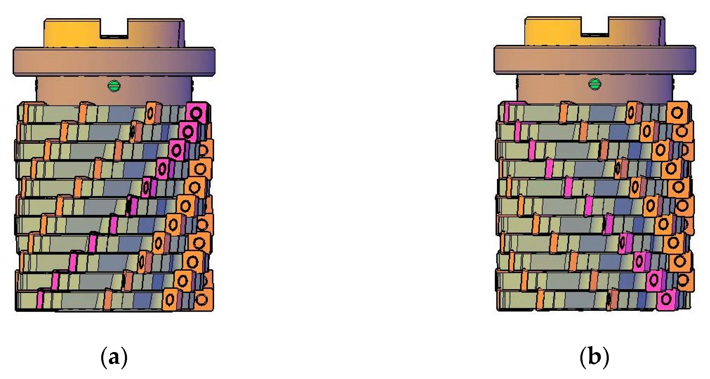
Furthermore, exploiting the symmetry of the tool and its versatility adequately mounting the elementary cutters on the shaft, a balanced milling cutter (in terms of axial force) can be obtained, as shown in
Figure 12 [
27]. The elementary milling cutters are differently rotated each from the next one at the two ends of the shaft.
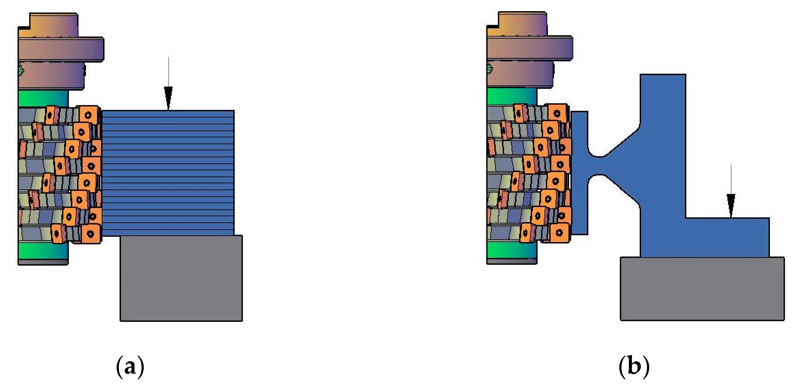
The modular milling cutter can be used for different jobs that involve machining parts with low stiffness. In
Figure 13 are presented two such cases [
27]. The tool’s active length can be adjusted by replacing the elementary milling cutters with spacers.
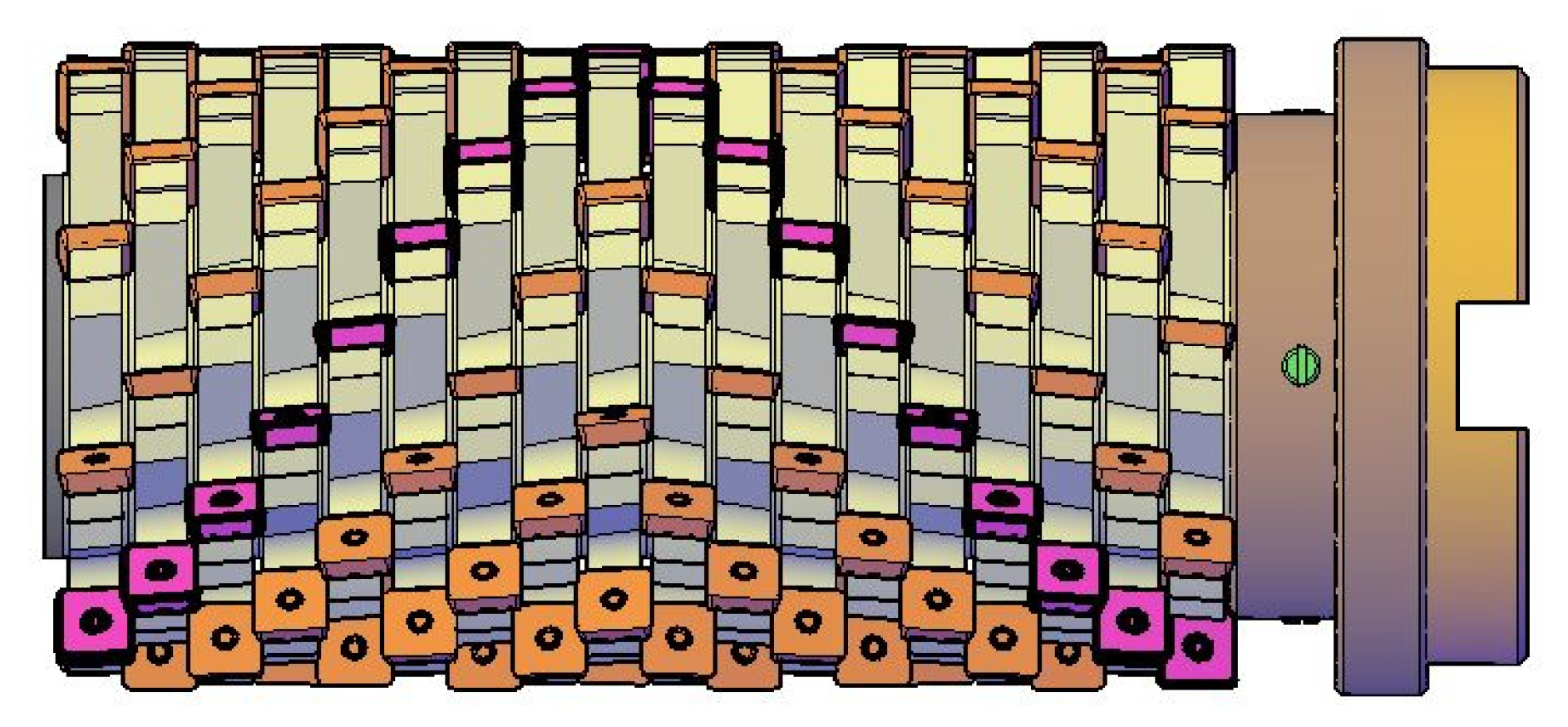
In
Figure 14 two possible combinations of the elementary milling cutter and the part machined by them are shown [
27]. The spacers are important for the shape of the modular tool, or for the adjustment of its active length. A symmetrical cutting tool plays an important role in machining asymmetrical parts.
5. Conclusions
The paper presents an integrated approach of designing the modular milling cutters. Some novel aspects can be found, such as the new particular way to assemble the elementary milling cutters on the shaft, the cooling system of the complex tool, and the exploitation of symmetry to obtain constructive and technological advantages for manufacturing.
The new shape of the shaft and reaming of the milling cutters brings several advantages, including the high capacity to transmit torque, about five times higher than the similarly sized classic assembly. What is indeed important is that the grooves, both on the shaft and in the milling cutter hole, do not need special cutting tools or special machine tools. They can be machined using common end mill and ball nose cutters. The high capacity to transmit torque is accompanied by a high precision of centring the elementary milling cutters on the shaft, facilitated by the smoothed cylindrical section of the hole, which forms a precise fit with the outer diameter of the shaft. The shape of the grooves and of the hole profile are very easy to manufacture with common technological means.
The self-cooling system feeds the entire cutting area with coolant. The particularity of the proposed solution is that by their design, the nozzles are able to send jets or curtains of coolant towards the axis of the milling cutter, instead of sending jets parallel, as other systems [
16] do. In this way the inserts are permanently cooled, even when they are not engaged in the workpiece. The coolant is delivered by the inner-cooling system of the machine tool, that is, at high flow and pressure. One can appreciate that the new cooling system is superior to other existing classic outer cooling ones [
16], because the coolant is distributed simultaneously on the entire side surface of the cutter, not only focused on a narrow area.
Symmetry is highly exploited to obtain multiple advantage including balanced forces in cutting process and the possibility of controlling the direction of the axial cutting force. The multiple symmetry of the profile of the milling cutter hole does not pose technical difficulties for its processing: there is no need for a complex dividing device, since the profile is controlled through the CNC program used to process it.
As designed, the modular milling cutter benefits from high versatility, being a unitary concept that is able to provide users with multiple choices of exploitation.
Due to its versatility, the modular milling cutter is very useful mainly for workshops or plants where small batch production is predominant. The same complex cutting tool can be reconfigured to fit to different specific machining cases, as can be seen in
Figure 13 and
Figure 14. Furthermore, elementary milling cutters with different diameters but same sized reaming can be mounted on the same grooved shaft. This extends the range of applications the modular milling cutter can be used for.
Further developments are foreseen for the project. They refer to using additive manufacturing for building some parts, e.g., the distributor. Benefitting from the capabilities of additive manufacturing technologies, the nozzles could be integrated in the distributor body so they form a single part. Using additive technologies, the shape of the network of channels in the distributor could be optimized to minimize the hydraulic losses that occur at the drastic change in the flow direction of fluid.
Once the new concept has been turned into a laboratory experimental demonstrator, the modular milling cutter will be subjected to mechanical tests, including vibration trials. The possible influence of the improved cooling conditions on the cutting forces will be investigated as well.
6. Patents
The work presented in the present manuscript had as its outcome a patent proposal, recorded under the title Modular Mill and Gang Mill Constructions with Adjustable Dimensional and Geometric Parameters and Interior Cooling System in Double Version and number RO132084 (A0)—30 August 2017. The authors of the patent proposal are the same as those of the present paper.
Author Contributions
Conceptualization, D.M.R., M.-V.D. and G.O.; methodology, M.-V.D. and G.O.; software, M.-V.D.; validation, D.M.R. and M.F.F.; writing—original draft preparation, M.-V.D., D.M.R. and M.F.F.; writing—review and editing, M.F.F.; supervision, D.M.R.; project administration, M.-V.D. All authors have read and agreed to the published version of the manuscript.
Funding
This research received no external funding.
Institutional Review Board Statement
Not applicable.
Informed Consent Statement
Not applicable.
Data Availability Statement
Data sharing is not applied.
Conflicts of Interest
The authors declare no conflict of interest.
References
- Oancea, G.; Drăgoi, M.V.; Ivan, N.V. CAD of Profiled Gang Cutter. In Romanian Journal of Technical Sciences, Aplied Mecanics, Tome 47, Proceeding of the International Conference on Manufacturing Systems, ICMAS 2002, Bucharest, Romania, 10–11 October 2002; Editura Academiei Române: Bucureşti, Romania, 2002; pp. 545–548. [Google Scholar]
- Oancea, G.; Ivan, N.V.; Lancea, C.; Oancea, C. The WinFP2006 System Used for Profiled Gang Cutter Design. In Proceedings of the 8th International MTeM Conference, Annals of MTeM for 2007, Cluj-Napoca, Romania, 4–5 October 2007; pp. 327–332. [Google Scholar]
- Beerli, B. Schneidwerkzeug. Patent CH-A-236811, 15 March 1945. [Google Scholar]
- Schmid, K. Milling Tool, Especially Gang Cutter. U.S. Patent 4242020 A, 30 December 1980. [Google Scholar]
- Schrader., G. Federfraser. Patent DE-C-163148, 7 June 1904. [Google Scholar]
- Nalley, P.D.; Slayton, J.R. Rotary Cutter Knife. U.S. Patent 3986543 A, 19 October 1976. [Google Scholar]
- Swanson, K.A.; Abeyta, W.J.; Doaf, S. Erodible Spacer Dicing Blade Gang Assembly. U.S. Patent 2011041308-A1, 24 February 2011. [Google Scholar]
- Lukina, S.; Krutyakova, M. Analytical Study of Modular Cutting Tools Dynamic Properties. In Proceedings of the MATEC Web of Conferences, International Conference on Modern Trends in Manufacturing Technologies and Equipment (ICMTMTE 2017), Sevastopol, Russia, 11–15 September 2017; Bratan, S., Gorbatyuk, S., Leonov, S., Roshchupkin, S., Eds.; 2017; Volume 129, p. 01061. [Google Scholar] [CrossRef][Green Version]
- Hijink, J.A.W.; Wolf, A.C.H. Measurements on the Dynamic Behaviour of Modular Milling Tools. CIRP Ann. 1992, 41, 113–116. [Google Scholar] [CrossRef]
- Ciofu, C.D.; Tabacaru, L.; Carausu, C.; Tataru, M. Computer Aided Design of an Modular Milling Gear Hob. In Proceedings of the International Conference ModTech, the 14th International Conference on Modern Technologies, Quality and Innovation (ModTech 2010), Slănic-Moldova, Romania, 20–22 May 2010; Nedelcu, D., Slatineanu, L., Mazuru, S., Milosevic, O., Eds.; pp. 211–214. [Google Scholar]
- Hunt, E. Modular milling goes high speed. Mod. Mach. Shop 1988, 61, 60–67. [Google Scholar]
- Brindasu, P.D.; Beju, L.D.; Cofaru, N. Generalized Approach to the Design of Boring Heads. In Proceedings of the 16th International Conference on Manufacturing Systems—ICMaS; Editura Academiei Române: Bucharest, Romania, 2007. [Google Scholar]
- Augspurger, T.; Koch, M.; Klocke, F.; Dobbeler, B. Investigation of Transient Temperature Fields in the Milling Cutter under CO2 Cooling by Means of an Embedded Thermocouple. In Proceedings of the Procedia CIRP, 12th CIRP Conference on Intelligent Computation in Manufacturing Engineering (CIRP ICME), Naples, Italy, 18–20 July 2018; Teti, R., Daddona, D.M., Eds.; 2018; pp. 33–38. [Google Scholar] [CrossRef]
- Yin, N.X.; Li, G.H.; Tan, G.Y.; Shen, C.; Xue, J. Design of the Feed Liquid System for an Internal Cooling End-milling. In Proceedings of the Journal of Physics Conference Series, 2nd International Conference on Fluid Mechanics and Industrial Applications, Guilin, China, 12–14 July 2018; p. 012061. [Google Scholar] [CrossRef]
- Quan, Y.M.; Liang, L.; Liu, Z.J. Design and Heat Dissipation Test of the Cutter with Heat Pipe Cooling. In Proceedings of the Progress of Machining Technology, 10th International Conference on Progress of Machining Technology (ICPMT2012), Tsubame, Japan, 25–27 September 2012; Chen, D., Narutaki, N., Fan, R., Ochi, A., Eds.; pp. 47–51. [Google Scholar]
- Cutting Tool Engineering. Available online: https://www.ctemag.com/news/articles/through-coolant-toolholders-efficient-economical (accessed on 29 January 2021).
- Xu, Z.; Xi, F.; Liu, L.; Chen, L. A Method for Design of Modular Reconfigurable Machine Tools. Machines 2017, 5, 5. [Google Scholar] [CrossRef]
- Abbas, A.T.; Anwar, S.; Abdelnasser, E.; Luqman, M.; Qudeiri, J.E.A.; Elkaseer, A. Effect of Different Cooling Strategies on Surface Quality and Power Consumption in Finishing End Milling of Stainless Steel 316. Materials 2021, 14, 903. [Google Scholar] [CrossRef] [PubMed]
- Saravanan, P.; Raj, D.S.; Hussain, S.; Shankar, V.R.; Raj, N. Optimization of jet position and investigation of the effects of multijet MQCL during end milling of Ti-6Al-4V. J. Manuf. Process 2021, 64, 392–408. [Google Scholar] [CrossRef]
- Damm, O.; Bezuidenhout, M.; Uheida, E.; Dicks, L.; Hadasha, W.; Hagedorn-Hansen, D. Yeast-based metalworking fluid for milling of titanium alloy—An example of bio-integration. CIRP J. Manuf. Sci. Technol. 2021. [Google Scholar] [CrossRef]
- Singh, G.; Aggarwal, V.; Singh, S.; Kumar, A. Influence of Nozzle Distance on Tool–Chip Interface Temperature Using Minimum Quantity Lubrication. In Advances in Production and Industrial Engineering, Lecture Notes in Mechanical Engineering; Pandey, P.M., Kumar, P., Sharma, V., Eds.; Springer: Singapore, 2021. [Google Scholar] [CrossRef]
- De Bartolomeis, A.; Shokrani, A. Electrohydrodynamic Atomization for Minimum Quantity Lubrication (EHDA-MQL) in End Milling Ti6Al4V Titanium Alloy. J. Manuf. Mater. Process. 2020, 4, 70. [Google Scholar] [CrossRef]
- Shokrani, A.; Betts, J. A new hybrid minimum quantity lubrication system for machining difficult-to-cut materials. CIRP Ann. 2020, 69, 73–76. [Google Scholar] [CrossRef]
- Roșca, D.M. A New Constructive Conception on Cutting Tools Used for Lathing Shaped Surfaces. In Proceedings of the 1st International Conference on Computing and Solutions in Manufacturing Engineering, Brasov, Romania, 16–18 September 2004; pp. 161–163. [Google Scholar]
- Roșca, D.M. The Functional Flexibility through the Modularisation of Cutting Tool Construction. In Proceedings of the 1st International Conference on Computing and Solutions in Manufacturing Engineering, Brasov, Romania, 16–18 September 2004; pp. 163–165. [Google Scholar]
- Rosca, D.M.; Folea, M.F. Grooved Shaft for Positioning and Driving in Rotational Movement of Reamed Milling Cutters Elements (Translated from Romanian—Arbore Canelat Pentru Poziționarea și Antrenarea în Mișcarea de Rotație a Componentelor Frezelor cu Alezaj). Patent Proposal RO 130751 A0, 30 December 2015. [Google Scholar]
- Rosca, D.M.; Oancea, G.; Drăgoi, M.V.; Folea, M.F. Modular Mill and Gang Mill Constructions with Adjustable Dimensional and Geometric Parameters and Interior Cooling System in Double Version. Patent Proposal RO 132084 (A0), 30 August 2017. [Google Scholar]
| Publisher’s Note: MDPI stays neutral with regard to jurisdictional claims in published maps and institutional affiliations. |
© 2021 by the authors. Licensee MDPI, Basel, Switzerland. This article is an open access article distributed under the terms and conditions of the Creative Commons Attribution (CC BY) license (http://creativecommons.org/licenses/by/4.0/).


