Abstract
We describe a method for constructing developable bands with N ≥ 3 half twists. Each band is formed by threading a flat rectangular strip through a scaffold made from identical circular cylinders and smoothly connecting its short ends. The N cylinders in a scaffold are arranged with N-fold rotational symmetry. The number of half twists in a band is equal to the number N of cylinders in its scaffold and each band inherits the symmetry of its scaffold. Each scaffold admits a family of bands of the same length but variable width up to a maximum value determined by the features of the scaffold. Apart from orientable and nonorientable unknots, our method allows for the construction of bands with the topology of torus knots. We detail the geometric properties of the construction, discuss certain fundamental restrictions that must be met to ensure constructability, and calculate the elastic bending energy of each band. The rotational symmetry underlying the construction is essential for obtaining the presented bands, as the general non-symmetric problem is even more complex and has not yet been investigated. The bands and their corresponding scaffolds can be used as structural elements in practical applications, one of which we describe and analyze. The construction serves as a basis for a general framework for building a large variety of scaffolds and the corresponding unstretchable bands. Together, these assemblies can be used in architectural, interior, and machine design. They also open new avenues for the layout of conveyor belts in factories, airports, and other settings.
Keywords:
structural scaffolds; orientable and nonorientable surfaces; torus knots; interior design; pure bendings; elastic bending energy PACS:
02.40.-k; 02.40.Hw; 89.20.Kk
1. Introduction
In 1930, Sadowsky [1,2] used a constructive argument to establish the existence of a family of isometric deformations from a rectangular strip to a Möbius band with one half twist, settling a controversy that had previously prevailed regarding the existence of such deformations. His construction involves threading a rectangular strip over three circular cylinders, one of diameter equal to the sum of the diameters of the remaining two, arranged so that their axes project onto an equilateral triangle. We present here a new, versatile construction for developable bands with N ≥ 3 half twists using N circular cylinders. For each choice of N, these cylinders are identical and are regularly distributed on a base circle to form a scaffold with N-fold rotational symmetry relative to the symmetry axis of the circle. Each band arising from our construction inherits the symmetry of its supporting scaffold. To convey a sense for the general construction, we show in Figure 1 a stepwise sequence of isometrically deforming a flat rectangular strip into a Möbius band that conforms to a scaffold made from three cylinders.
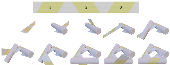
Figure 1.
Sequence of intermediate steps in isometrically threading a flat rectangular strip (top) into a Möbius band (also shown in Figure 8) through a scaffold of three cylinders. The properties that a scaffold must have to allow for the construction of a band are the primary focus of this paper. Starting from the flat configuration, the first cylinder is placed on the strip making contact at the line where parallelogram 1 (yellow and denoted by “1” on the strip) begins. The band is next wrapped around the first cylinder until parallelogram 1 conforms fully to the cylinder. The second cylinder is next placed on the band, making contact along the line where parallelogram 2 begins and the band is wrapped around the second cylinder, until parallelogram 2 conforms fully to the cylinder. The third cylinder is finally put into place and parallelogram 3 is wrapped over it in the same fashion as parallelograms 1 and 2 were wrapped around the first and second cylinders. This aligns the vertical edge of the strip to the right of parallelogram 3 with the edge of the strip to the left of parallelogram 1 and allows for the strip to be smoothly joined into a band, thereby creating a flat trapezoid from the portions of the strip to the left and right of parallelograms 1 and 3.
Having established the existence of a developable Möbius band, Sadowsky [1,2] also formulated a variational problem for determining the equilibrium shape of a free-standing Möbius band with one half twist and reduced the underlying surface integral for the bending energy to an integral over the midline of the band, restricting attention to bands with infinitesimal width-to-length aspect ratios. Although Sadowsky’s [1,2] construction is highlighted in an expository article by Schwartz [3], the literature that has developed in response to Sadowsky’s [1,2] paper has so far focused entirely on various features of his variational problem. Wunderlich [4,5] generalized Sadowsky’s [1,2] dimensional reduction to bands with finite width-to-length aspect ratios. Guven et al. [6] explored the influence of the constraint of isometry on the boundary conditions that apply along the free edge of an unstretchable surface. Seguin et al. [7] extended Wunderlich’s [4,5] work to account for the constraints needed to ensure that a solution to the dimensionally reduced variational problem constitutes an isometric and locally injective deformation from a rectangular strip to an unknotted Möbius band, allowing for any number of half twists, and derived the corresponding Euler–Lagrange equations and jump conditions. Starostin and van der Heijden [8] were the first to develop a numerical method for minimizing the Wunderlich [4,5] functional and applied that method to determine the shape of a Möbius band with one half twist. Subsequently, Starostin and van der Heijden [9] applied their method to determine the shapes of multiply twisted bands with and without knots. Shen et al. [10] developed an alternative dynamical scheme for minimizing the Wunderlich [4,5] functional numerically and applied their scheme to determine the shape of a Möbius band with one half twist. In a departure from efforts based on the Wunderlich [4,5] functional, Bartels and Hornung [11] established qualitative properties of Möbius bands that minimize the surface bending energy underlying the dimensional reductions of Sadowsky [1,2] and Wunderlich [4,5] and used numerical simulations to illustrate and bolster their analytical findings. Moore and Healey [12] developed and applied numerical methods to construct and explore the stability of Möbius bands. Velimirović and coworkers [13,14] exposed connections between the literature inspired by Sadowsky’s [1,2] work and mathematical investigations directed at minimizing the Willmore [15] functional.
Distinct from the publications cited in the preceding paragraph, we develop here a new construction inspired by Sadowsky’s [1,2] original construction. We are not aware of any existing works in this direction. Any of our scaffolds can be designed by selecting three independent parameters: a positive number r representing the radius of a base circle upon which each scaffold is built, an angle between 0 and which depends on the number of cylinders in the scaffold and their connectivity, and an angle between 0 and which determines the orientation of the cylinders relative to the plane of the base circle. Each admissible choice of r, , and determines the dimensions and relative orientations of the cylinders that form the scaffold, and the same goes for the length and maximum width of any band that can be constructed upon the scaffold.
The simplification afforded by our use of identical cylinders carries a cost. Sadowsky’s [1,2] construction yields Möbius bands with curved portions that cover only half of each of the three cylinders involved and any of his constructions can therefore be achieved with appropriately oriented cylinders of half-circular cross section. In our construction, the turning angle over which the band covers each cylinder is not simply but varies from scaffold to scaffold. We determine explicitly in terms of the design angles and .
As with Sadowsky’s [1,2] construction, our construction yields developable bands which alternate between flat sections and curved sections that conform to the cylinders of the scaffold. Any such band inhabits a shape obtained by a pure bending of a flat rectangular strip. If such a strip is modeled as a homogeneous, isotropic two-dimensional material, then the energy stored in elastically bending it into a band depends at most on the mean curvature of the deformed shape. For our constructions, one principle curvature vanishes and the other is equal to the diameter of the cylinders that comprise the underlying scaffold. A closed form expression for the total bending energy E can therefore be obtained for any of our constructions. We display that expression in the particular case where the bending energy density depends quadratically on the mean curvature of the band. In addition to complex dependence on the design parameters r, , and , we find that E scales linearly with both the half-width w of the band and inversely with the radius R of the cylinders that form the underlying scaffold.
We show in Section 2.3 that our construction can be applied to create load bearing structures that are easily assembled and disassembled, as exemplified by a table made from a scaffold with three cylinders and the corresponding Möbius band.
For perspective, we discuss generalizations of our construction by, for example, relaxing the requirement that all cylinders must be identical or by allowing the use of more general (not just right circular) cylinders and cones for the scaffold. In conclusion, we formulate a conjecture concerning the constructability of -twisted bands using only cylinders.
2. Results
2.1. Construction
The geometrical features of a band which can be constructed upon a scaffold are entirely determined by the properties of that scaffold, with the exception of the width of the band, which can be chosen freely up to a maximum length, which again depends on that scaffold. For clarity, we consider scaffolds alone before addressing the corresponding bands. The basic properties of our scaffolds are presented in Section 2.1.1. A smooth closed curve of piecewise constant curvature that winds around a scaffold is described in Section 2.1.2 and a limit for the constructability of that curve is derived in Section 2.1.3. Bands are finally considered in Section 2.1.4.
2.1.1. Scaffolds
Each scaffold we consider is constructed relative to a base circle C of radius . To construct a scaffold of identical cylinders, we first identify N equidistant points on C, place a straight line tangent to C at each such point, and rotate each such line around its radial axis going through the center of C and the contact point of the line. This rotation out of the plane of C is performed by an angle satisfying
while maintaining contact with C, as illustrated in Figure 2.
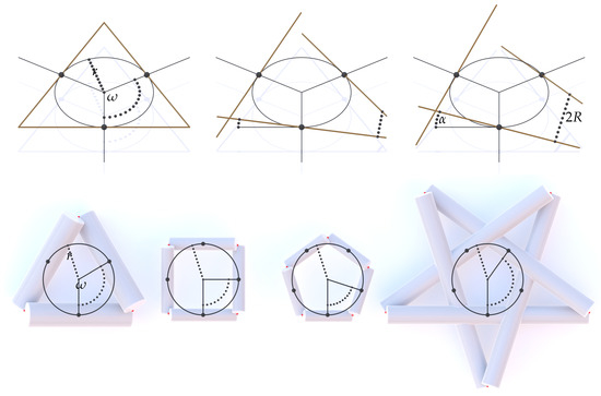
Figure 2.
(Top) N line segments (here shown for the case of ) equidistantly distributed on a base circle of radius r. These lines serve as the axes of the cylinders once they have been rotated around radial axis of the base circle C by the angle such that the shortest distance between associated lines equals . (Bottom) The basic construction after cylinders have been added for , 4, 5 (scaffolds , , , respectively) and and for cylinders (scaffold ) and . The indicated angle depends on the number N of cylinders as well as k and is given by . The integer specifies that a cylinder has a common point (in red) with each of the two “k-th” neighboring cylinders. For , we obtain convex scaffolds (scaffolds , , ). For a nonconvex scaffold () to be possible (scaffold ) two conditions must be satisfied: and k is not a divisor of N.
We emphasize that the common sense of rotation for all lines, which is either counterclockwise or clockwise, specifies the chirality of the scaffold and all subsequent objects in the construction (namely the connecting curve and the band), as discussed below. Next, we simultaneously allow the lines to grow radially into circular cylinders until their common radius reaches a certain critical value R that is related to the presence of isolated points of tangential contact between certain pairs of cylinders. These isolated tangential contact points between pairs of cylinders are the crucial geometric feature that allows our construction to work because they lead to a common plane tangential to both cylinders in which a corresponding flat section of a spanning band lies. We say that pairs of cylinders that possess such points of contact are ‘associated’. Each cylinder of a scaffold is generally associated with two other cylinders that are removed from it by cylinders. The scaffolds form regular polygrams which can be further differentiated into two families. For , each cylinder is associated with its two immediate neighboring cylinders, leading to scaffolds like those depicted in Figure 2 for and . The cylinders in this type of scaffold exhibit tangential points of contact but do not intersect. For the contact points form regular polygons (with Schläfi symbol ) and we refer to scaffolds of this kind as convex. The scaffolds obtained for are distinguished by the presence of contact or overlap between cylinders that are not associated, leading to scaffolds like that shown in Figure 2 for and . Scaffolds of this kind form regular star polygons (with Schläfi symbol ) and we refer to them as nonconvex. If , then a scaffold of identical cylinders cannot be built unless k satisfies and the ratio is not a natural number (or, equivalently, N and k are “co-prime”). If is a natural number, then the cylinders overlap to create a scaffold consisting of only scaffolds. Hence, no generality is lost by stipulating that is not a natural number.
Each choice of and yields a scaffold with N-fold rotational symmetry. In such a scaffold, the distance between two adjacent points on the base circle C is given by , with
See Figure 2 for depictions of for the particular scaffolds consisting of and cylinders, for which case k is necessarily equal to unity, and cylinders for and . The radius R of each cylinder in a scaffold is completely determined by r, , and , as is the length L of the cylinders needed to ensure that they extend to contact points with two other associated cylinders, see Figure 3.
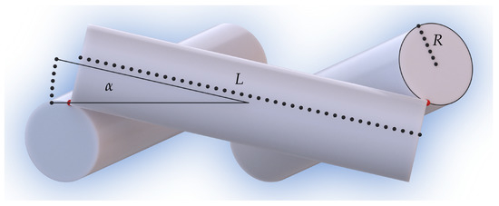
Figure 3.
Side view of the basic construction for displaying the tilt angle , the length L of the cylinders (granted that they are extended until their common endpoints, shown in red, meet), and the radius R of the cylinders.
In the Appendix A, we find that R and L can be expressed as
where defined through and such that
measures the half-angle between the axes of the associated cylinders in the scaffold. Although identities that determine and consistent with (5) can be used in (4) to express R and L solely in terms of r, , and , we omit those expressions for brevity. What is evident from the foregoing discussion is that three independent parameters are sufficient to design any one of our scaffolds.
2.1.2. Connecting Curve of a Scaffold
For each choice of the angle and a certain range of the tilt angle that we consider in Section 2.1.3, the associated rods of a scaffold built as described in Section 2.1.1 can be connected by a smooth closed space curve with piecewise constant curvature, consisting of N identical circular helices separated by N identical straight line segments. We conjecture here that is the shortest closed curve which entwines all cylinders of a scaffold. Whereas a convex scaffold () result in an unknotted curve , a nonconvex scaffold () leads to an torus knot. Each circular helix is necessarily of radius R and pitch . Additionally, as we show in the Appendix A, the turning angle of each helix can be expressed as
where the usual principle values of the arccos function with the range are used. With reference to (5), we thus see that is completely determined by the angles and (via ) entering the design of each scaffold. Each helix is therefore of length
where , given by
measures the distance that the helix traverses along the cylinder axis, as illustrated in Figure 4 for the special case of a scaffold consisting of cylinders.
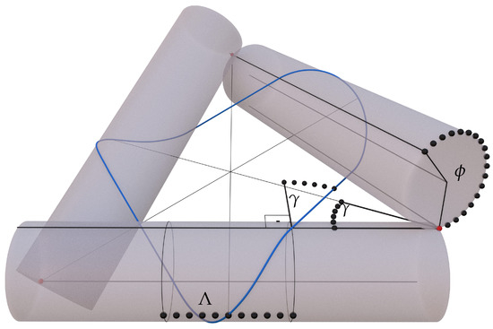
Figure 4.
The connecting curve (in blue) for . Also shown is the incidence angle at which meets the cylinder; also appears as half of the angle between the axes of two cylinders which have a common point (in red). Also depicted is the angle for which is covering each cylinder and the length for which a helical part of traverses along the cylinder axis.
Moreover, the straight line segment connecting the helices on a pair of associated cylinders in the scaffold has length
2.1.3. Maximum Tilt Angle
For each choice of satisfying (3), there exists a maximum value of the tilt angle above which the associated cylinders of a scaffold cannot be connected by a closed space curve of the kind discussed in Section 2.1.2. This upper bound is achieved if the connecting curve intersects the points where each pair of associated cylinders are in tangential contact, as illustrated in Figure 5 for the special case of a scaffold consisting of cylinders. We next characterize as a function of . The length a of the shortest path between a point at which a pair of associated cylinders is in tangential contact and the connecting curve is given by
as depicted in Figure 5 for the special case of a scaffold of cylinders. The curve therefore passes through the contact point if . With reference to the expressions (4) and (8) determining R, L, and in terms of the design parameters r, , and for the scaffold, the condition takes the form of a transcendental equation:
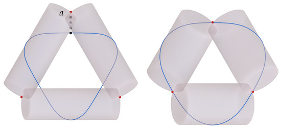
Figure 5.
(Left) Illustration of the length a of the shortest path between a contact point of two cylinders (in red) and the connecting curve (in blue) for the case . The length a bounds the possible half-width w of the band as discussed in Section 2.1.4. (Right) For the maximum tilt angle of the scaffold, the length a vanishes and the curve intersects all contact points.
For any admissible choice of , the maximum angle is determined by solving (12). Numerical approximations of for all possible combinations of N and k with are given in Table 1 and are plotted in Figure 6, where the scaffold type is identified with the abbreviated notation .

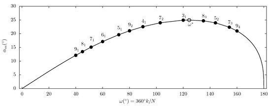
Figure 6.
The maximum tilt angle (see Figure 3) for which the connecting curve can be constructed as a function of resulting from the solution of the transcendental Equation (12). Indicated are all scaffolds with and the highest possible value for occuring at (with ) which is close to (with ). Considering nonconvex scaffolds, it is easy to find a case with , for example, (with ). Since every real number can be approximated arbitrarily close by a rational number, one can find a nonconvex scaffold with being arbitrarily close to .
From Figure 6, we see that as defined by (12) is a nonmonotonic function of . On a basic level this can be confirmed by considering the two limits and and demanding that the function attains an extremum somewhere in its range of admissible values. The limit can be thought of as the limit , with k being finite, for which the midline of the band approaches the radius r of the base circle C. For , the midline is a braided torus knot which contracts to C on passing to the limit . The limit is harder to picture since it corresponds to taking while simultaneously taking . Under this limit, the point of tangency of each pair of associated cylinders tends to the point at infinity and the cylinders become parallel.
Given a choice of satisfying (3), we hereafter restrict to obey
2.1.4. Planar Development and Maximum Width of a Band
Given a base circle of radius and an angle satisfying (3), the connecting curve of any scaffold with tilt angle satisfying can serve as the midline of a developable band. Like the curve , the bands that can be constructed on a scaffold are (ribbon-like) unknots or torus knots depending on whether the scaffold is convex () or nonconvex (). We use the notation to identify the type of any band, exactly as with scaffolds. Moreover, since each winding of the band around a cylinder introduces a -twist in the orientation, a band may be orientable or nonorientable depending on the number N of cylinders in the supporting scaffold. If N is odd, we obtain nonorientable (Möbius) bands, and if N is even, orientable bands. An illustration of a band is shown in Figure 7. While any such band is of the same length l as , its half-width w must not exceed a certain maximum value that is determined by r, , and . Each of these bands consists of N isosceles trapezoids (or, in the extreme limit, isosceles triangles) separated by N curved sections that result from bending, without stretching, parallelograms onto the cylinders of the scaffold. While the flat trapezoidal (or triangular) sections of the band have base angle , the interior angles of the curved sections are bent from parallelograms with interior angles . The heights of these trapezoids (or triangles) and parallelograms must necessarily equal the width of the band. See Figure 8 for an illustration of a band and its planar development in the particular case of a scaffold consisting of cylinders. Also, see Figure 1 for a step-by-step sequence of the process of isometrically deforming a flat rectangular strip into a band.
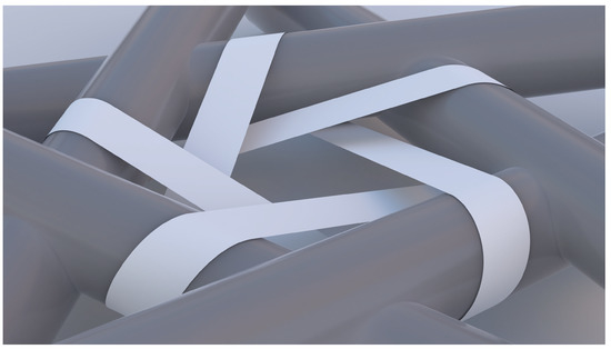
Figure 7.
Example of a nonconvex scaffold with a knotted, non-self-intersecting band. The scaffold is identical to that in Figure 2 () with and . The corresponding band is a torus knot and a nonorientable Möbius band.
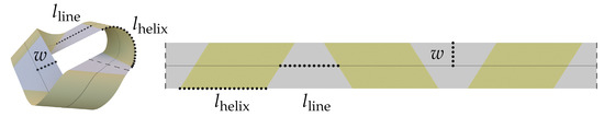
Figure 8.
A band (left) and its flat rectangular development (right). The trapezoids (grey) in the development remain flat in the deformed state while the parallelograms (yellow) lie on the curved cylinder surfaces. The midline lengths of the trapezoids () and parallelograms () and the half-width w of the band are indicated. The opening cut of the band (emphasized by a dashed line) is located at the middle of one of the trapezoids.
A knotted band can self-intersect in several ways, as illustrated, for instance, in Figure 9. Detecting such self-intersections is generally a difficult problem that can only be solved numerically. For unknotted bands, only one type of self-intersection is possible and this occurs only for the band. In this situation the edge of the band collides with the axis of symmetry at the center of the base circle C if the half-width w is equal to
as shown in Figure 10.
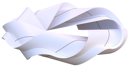
Figure 9.
A knotted band with maximal band width for the prescribed , extending the edge out to the common points. The band clearly self-intersects along a closed curve.
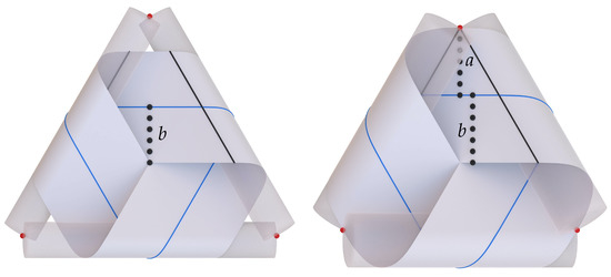
Figure 10.
(Left) Illustrating the length b of the shortest path between the center of the construction and the connecting curve (in blue) for the case . The half-width w of the band must not exceed the length b otherwise the band self-intersects. (Right) For the special angle the case occurs and the band can extend from the center out to the contact point, see Section 2.1.3 for the definition of a.
An interesting special configuration appears for , where a is as defined in (11). In this singular case, the band can extend from the center to the common point, as depicted in Figure 10 for the case . This configuration is related to a specific critical tilt angle we denote by which is given as the solution to the transcendental equation
which differs from (12) only by the presence of the second contribution to the parenthetical term in the numerator on the left-hand side. For unknotted bands, we can distinguish three different cases: , , and . For , (15) has the nontrivial solution . This leads to the scaffold and corresponding band of maximal width depicted on the right in Figure 10. For , the only solution to (15) is , meaning that the four cylinders of the supporting scaffold degenerate to line segments that form a flat square frame and that the associated band is completely flat. For we have always and (15) has no solution. Thus, since the half-width w must obey the restriction , the unknotted band with can never self-intersect in the center of its scaffold. In general (also for knotted bands), a nontrivial with exists only for bands with .
2.2. Elastic Bending Energy of a Band
Consider a flat rectangular strip modeled as a homogeneous, isotropic two-dimensional material. From the classical theory of plates, as described for instance in the authoritative treatise of Naghdi [16], the energy stored, per unit area, in elastically deforming such a strip to a surface must be an isotropic scalar-valued function, say , of the metric and curvature tensors of . Let the strip form the band corresponding to a scaffold consisting of N identical cylinders built on a base circle of radius r with defined by (2) satisfying (3) and tilt angle satisfying . To achieve this deformation, the strip must be of length l given in terms of r, , and by (10). Additionally, we assume that the half-width w of the strip is sufficiently small to ensure that no overlaps of the kind discussed in Section 2.1.4 are present. Since the process of threading the strip through the scaffold involves only bending, the metric tensor of the band is equal to that of the strip, namely the two-dimensional identity tensor, with the consequence that the Gaussian curvature K of the band vanishes identically. Under these circumstances, reduces to a function, say , of the mean curvature H of the band:
Recognizing that
with R, the radius of the cylinders that comprise the scaffold, being determined from r, , and through (4), we infer from (16) that the total bending energy E of the band is given by
where denotes the total area of the curved segments of the band. If, in particular, depends quadratically on H, as is commonly assumed in theories for plates, in which case (16) specializes to
with being the constant bending modulus, we then see from (4), (6)–(8), and (18) and (19) that the total dimensionless bending energy of the band has the explicit form
We thus find that the dimensionless bending energy of a band of half-width w constructed upon a scaffold of N cylinders designed on a base circle C of radius r with design angles and that respectively satisfy (3) and (13) scales linearly with the ratio of the half-width of the band to the radius of C but depends intricately on and .
The particular choice (19) of the energy density can be interpreted as a specialization of a model introduced by Germain [17], who considered reference shapes with intrinsic mean curvature and allowed for general quadratic dependence on the principal curvatures and of the deformed surface. In terms of the mean and Gaussian curvatures, Germain’s energy density reads
with being an additional modulus that accounts for energy stored in connection with any changes of length that accompany bending. Evidently, (21) reduces to (19) for any isometric deformation of a flat reference shape. The model (21) subsequently became prominent in the early literature on plates, gained interest among geometers and analysts, and was rediscovered in works concerning biomembranes. Perspectives and comprehensive references concerning the developments in these and other relevant disciplines are provided by Naghdi [16], Stoker [18], Weiner [19], Nitsche [20], Seifert [21], Kuwert and Schätzle [22], Deserno [23], and Guven and Vázquez-Montejo [24].
2.3. Force Needed to Tighten an Unknotted Band on Its Supporting Scaffold
So far, we have treated each of our scaffolds as a rigid object upon which bands of certain length and a range of widths can be perfectly fitted. With a view to using our constructions as structural elements, we consider a scaffold consisting of cylinders, , and title angle and a band of length l determined in terms of r, , and through (10), width w less than the maximum value obtained from (11) and (14), and bending modulus as a system (In choosing , we have restricted attention to constructions that yield unknotted bands. The counterpart of the question considered here is more complicated for because the cylinders of the corresponding scaffolds generally overlap). We envision a situation in which the scaffold is rigidly supported by reactive forces normal to the plane of its base circle C and each cylinder is subject to a force , where denotes the gravitational acceleration, directed toward the plane that supports the scaffold. We then determine the minimum value of m needed to ensure that the system is in static equilibrium. To simplify the analysis, we treat the cylinders as rigid bodies and neglect the weights of the cylinders and the band. We also suppose that the cylinders are capped by half spheres, so that all reactive and applied forces act along their axes.In Section 3, we consider a practical application of this problem in which the total force applied to the scaffold is due to the mass m of the platform. (See, also, Figure 13.)
We take each cylinder of the scaffold to be of total length
where and respectively represent extensions toward the supporting plane of the scaffold and toward the plane where the loads are applied to the scaffold. We begin with the moment balance for an individual cylinder and determine how an applied force couple created by the pair of forces (the applied load) and (the reaction of the supporting plane) is transmitted to the contact points at which the cylinder is tangent to its associated cylinders, resulting in a force couple with a corresponding pair of forces and at those points, see Figure 11.
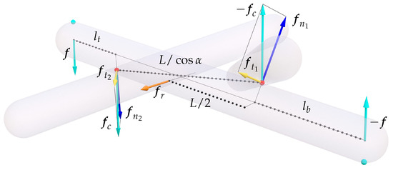
Figure 11.
The relevant forces on a cylinder for a band construction if vertical loads are applied at the ends of the cylinder through a heavy platform and the floor (contacting at the position of the cyan balls) leading to a force couple. This results in a force couple of magnitude at the common points of the cylinder with the other two cylinders (red balls). The force is then split up into normal () and tangential () components to the cylinder surfaces at the common points. The sum of the forces leads to a radial force acting on the cylinder which needs to be balanced by the band.
The balance reads
where and being the perpendicular distances between the lines of action for the two pairs of forces. The forces normal to the contacting cylinder surfaces at the contact points are
where and are the respective normal vectors (with ) defined in the Appendix A. The normal forces and are balanced by the reactive forces of the other cylinders. The tangential forces at the contact points are then given by
Finally, the resulting force acting on the midpoint of the original cylinder (excluding the extensions of length and ) is radially pointing outward and reads
Using the foregoing relations, we calculate the magnitude of to be
To answer the question how much of a weight the platform has to exert for the band to be tightened, we now consider the following subproblem shown in Figure 12.
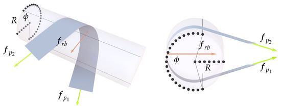
Figure 12.
A band wrapped around a cylinder. The magnitude of the pulling forces and necessary to tighten the band is given in (29).
If a band is wrapped around a cylinder, how much of a tangential pulling force has to be exerted on the ends of the band for it to be tight? Here, “tight” means that the band is either in touch with the cylinder surface or straight. The problem as illustrated in Figure 12 can be approached easily if we imagine the band to be wrapped around the cylinder in a conveyer belt fashion. Then, the vector and the tangent vector of the path (arc length parameterized by ) for the midpoint of one of the short edges of the band (at which the force is applied) during the wrapping motion are always parallel. Therefore, the work integral simplifies and is then equated to the bending energy
leading to the somewhat surprising result that the magnitude of the necessary force
does neither depend on the angle for which the band is covering the cylinder nor the incidence angle . The resulting force exerted by the band on the cylinder is then given by the sum of the two tangential pulling forces of magnitude acting on the band. The force is radially pointing inward and has the magnitude
The forces and have to be antiparallel and equal in magnitude to balance each other, leading to an equilibrium in the table construction. If we equate (27) and (30), we find the necessary mass m of the platform for the band to be tightened
To obtain an estimate for m, we consider a table with the proportions identical to the assembled one shown in Figure 13, using , , (resulting in ), , , . Even if we assume a rather high value of (a rough estimate for thicker paper of about ), we find a necessary mass of only . The canvas-like material we use for the band of the table shown in Figure 13 certainly has a much lower bending modulus and therefore an even lower necessary mass m. Thus, we conclude that for all practical applications the necessary mass of the plate needed to keep the band tight is exceeded by several orders of magnitude. In other words, on earth the band will always be tight.
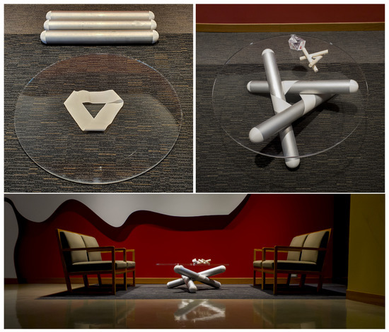
Figure 13.
Photographs of a table made from three aluminum cylinders (with 3D-printed spherical white caps), an acrylic plate, and a band (a synthetic printing canvas). (Top left) The disassembled parts. (Top right) The assembled table. (Bottom) The table in relation to the surrounding chairs. Each cylinder has a radius of mm, a total length (without the spherical caps) of mm, and a mass (including the spherical caps) of 3.7 kg. The band has a length of mm, a half-width of mm, and a thickness of 0.28 mm. The short ends of the synthetic band were connected using an ultrasonic welder. The acrylic plate has a diameter of 1 m, a thickness of 18 mm, and a mass of 17 kg. The values for R and l are chosen to yield the value for the tilt angle. The total height of the table is 366 mm.
To formally determine the mass that the cylinders alone would need to have to tighten the band is a much more involved problem because of their nontrivial spatial orientation. We therefore describe a simple approximation for the influence of the weight of the cylinders. Consider an idealization whereby the entire mass of each cylinder is concentrated as two point masses on the cylinder axis at the beginning and end of the cylinder. Then the force exerted by the point mass at the floor would be balanced by the floor itself and would not contribute any further. The force exerted by the point mass at the top of the cylinder would act identical to the load that the tabletop exerts. So, if the total mass of N cylinders were twice the necessary mass of the tabletop, then the cylinders would exert approximately the same force on the band as the tabletop. In light of the very small necessary mass discussed in the previous paragraph, the mass of the cylinders alone should be sufficient to tighten the band in all practical applications.
3. Discussion
The reported results nicely illustrate how the presence of an underlying symmetry (in this case an N-fold rotational symmetry) can lead to the discovery of new geometric structures that would be difficult to imagine in the absence of the assumed symmetry. The construction concept of a single common point for two associated cylinders can readily be generalized to systems where cylinders have different lengths and diameters. A simple example exploiting two-fold rotational symmetry is shown in Figure 14. The next step would be to give a general algebraic prescription how to construct bands starting on a cylinder and successively adding more cylinders with choosable dimensions, positions and orientations, given certain geometric constraints. Locally these constraints would still allow for the selection of several design parameters freely. However, the global constraint that the band must be closed constitutes a highly nontrivial condition. This is reminiscent of the problem for closed kinematic chains which locally follow simple geometric constraints but the overall closing of the chain couples all constituents with each other. Another generalization step would be to lift the restraint of using just right circular cylinders and allow for general cylinders and cones.
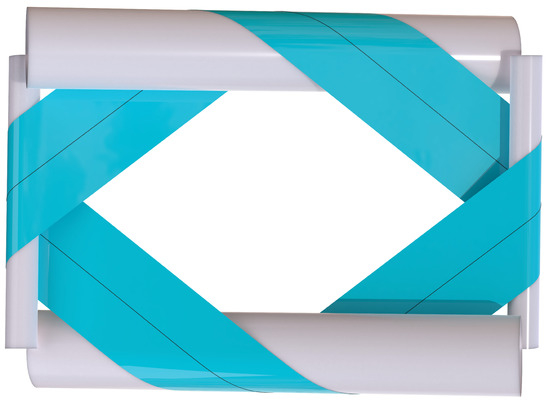
Figure 14.
Generalization of the construction idea to cylinders of different lengths and diameters.
Noting that Sadowsky’s classical construction resulted in a band with a -twist and our bands have -twists with , one is naturally led to the question of how to construct a -twisted band. If self-intersections are allowed, an answer is very easy: Take two parallel cylinders which do not touch and wind the band around them in a “figure eight” fashion. However, without self-intersections, the answer seems to be more complicated. We state here the conjecture that it is impossible to construct a -twisted band without self-intersections with just two cylinders. The interesting question is: How many cylinders are needed?
As indicated in Section 2.1.4, nonconvex scaffolds which lead to knotted bands can have nontrivial self-intersections different from the one discussed, as exemplified in Figure 9. An interesting open problem would be to classify the possible categories of self-intersections and how these are related to the connectivity of the scaffold.
Our constructions have the potential to serve as structural elements with load carrying capacity, as shown in the photographs, in Figure 13, of a band that binds, entirely without recourse to fasteners or adhesives, three aluminum cylinders (with 3D-printed spherical caps) which support an acrylic tabletop parallel to the plane of construction. The band is made from a synthetic printing canvas and is the limiting factor for the load-carrying capacity of the assembly because the band is likely to tear at some critical load. During a load test, the table depicted in Figure 13 supported an additional mass of 103 kg without difficulty, showing that this particular assembly can easily carry a mass of 120 kg (on planet earth). Since they are easy to assemble and disassemble, structural elements like these reduce the space needed for storage or transport.
All possible bands with can be explored in an interactive viewer available online at https://hannes.home.oist.jp/projects/babylon/cylinderband.html (accessed on 8 March 2021). After selecting , one can set the tilt angle and the band width freely within their bounds.
Author Contributions
Conceptualization, J.S. and E.F.; software, J.S.; formal analysis, J.S. and E.F.; writing—original draft preparation, J.S. and E.F.; visualization, J.S. and M.G.; supervision, E.F. All authors have read and agreed to the published version of the manuscript.
Funding
The authors gratefully acknowledge support from the Okinawa Institute of Science and Technology Graduate University with subsidy funding from the Cabinet Office, Government of Japan.
Conflicts of Interest
The authors declare no conflict of interest.
Appendix A
We provide concise derivations of the geometric quantities central to the construction. Referring to Figure A1, we introduce a right-handed orthonormal basis with normal to the plane of the base circle C and directed from the center of an arbitrarily chosen cylinder to the center of C. This setup is illustrated in Figure A1, the chosen cylinder is in front of the remaining two cylinders and its axis lies in the plane spanned by and . We begin with the vector directed from the center of the chosen cylinder to the center of its associated cylinder on its immediate right, as defined by
Let and be unit vectors aligned with the axes of the chosen cylinder and the associated cylinder on its immediate right, respectively, with directed away from the common point of the cylinders and directed toward that point. (Common points are indicated by red spheres in Figure A1.) Relative to the basis , these vectors read

Figure A1.
A technical sketch of the cylinders for introducing the relevant quantities.
Figure A1.
A technical sketch of the cylinders for introducing the relevant quantities.

We next calculate the length L of the cylinders. To achieve this, it suffices to determine the value of L for which the length of the vector directed from the axis of the chosen cylinder to the axis of its associated cylinder on the immediate right is minimal. Since , it follows that is minimal if and only if , with the consequence that
Since, for this choice of L, is equal to the diameter of the cylinders (as illustrated in Figure A1), it also follows that
As is apparent from Figure 4 and Figure A1, the incidence angle is directly related to the unit vectors along the cylinder axes and is thus determined by or, equivalently,
To determine the angle traversed by the helix that winds around each cylinder, we introduce the counterpart of the vector corresponding to the chosen cylinder and its associated cylinder on the immediate left. Since each cylinder is of the same radius, . Recalling that and observing that relative to the basis , and only differ by the signs of their components along , as illustrated in Figure A1, we find that is given by
References
- Sadowsky, M. Ein elementarer Beweis für die Existenz eines abwickelbaren MÖBIUSschen Bandes und die Zurückführung des geometrischen Problems auf ein Variationsproblem. Sitzungsber. Preuss. Akad. Wiss. Phys.-Math. Kl. 1930, 22, 412–415. [Google Scholar]
- Hinz, D.F.; Fried, E. Translation of Michael Sadowsky’s Paper “An elementary proof for the existence of a developable Möbius band and the attribution of the geometric problem to a variational problem. J. Elast. 2015, 119, 3–6. [Google Scholar] [CrossRef]
- Schwarz, G.E. The dark side of the Moebius strip. Amer. Math. Mon. 1990, 97, 890–897. [Google Scholar] [CrossRef]
- Wunderlich, W. Über ein abwickelbares Möbiusband. Monatsh. Math. 1962, 66, 276–289. [Google Scholar] [CrossRef]
- Todres, R.E. Translation of W. Wunderlich’s “On a developable Möbius band”. J. Elast. 2015, 119, 23–34. [Google Scholar] [CrossRef]
- Guven, J.; Müller, M.M.; Vázquez-Montejo, P. Isometric bending requires local constraints on free edges. Math. Mech. Solids 2019, 24, 4051–4077. [Google Scholar] [CrossRef]
- Seguin, B.; Chen, Y.-C.; Fried, E. Closed unstretchable knotless ribbons and the Wunderlich functional. J. Nonlinear Sci. 2020, 30, 2577–2611. [Google Scholar] [CrossRef]
- Starostin, E.L.; van der Heijden, G.H.M. The shape of a Möbius strip. Nat. Mater. 2007, 6, 563–567. [Google Scholar] [CrossRef] [PubMed]
- Starostin, E.L.; van der Heijden, G.H.M. Equilibrium shapes with stress localisation for inextensible elastic Möbius and other strips. J. Elast. 2015, 119, 76–112. [Google Scholar] [CrossRef]
- Shen, Z.; Huang, J.; Chen, W.; Bao, H. Geometrically exact simulation of inextensible ribbon. Comput. Graph. Forum 2015, 34, 145–154. [Google Scholar] [CrossRef]
- Bartels, S.; Hornung, P. Bending paper and the Möbius strip. J. Elast. 2015, 119, 113–136. [Google Scholar] [CrossRef]
- Moore, A.; Healey, T. Computation of elastic equilibria of complete Möbius bands and their stability. Math. Mech. Solids 2019, 24, 939–967. [Google Scholar] [CrossRef]
- Velimirović, L.S.; Ćiric, M.S.; Velimirović, N.M. On the Willmore energy of shells under infinitesimal deformations. Comput. Math. Appl. 2011, 61, 3181–3190. [Google Scholar] [CrossRef]
- Velimirović, L.S.; Cvetković, M.D.; Najdanović, M.S.; Velimirović, N.M. Variation of shape operator under infinitesimal bending of surface. Appl. Math. Comput. 2013, 225, 480–486. [Google Scholar] [CrossRef]
- Willmore, T.J. Note on embedded surfaces. An. Şti. Univ. “Al. I. Cuza” Iaşi Secţ. I a Mat. (NS) 1965, 11B, 493–496. [Google Scholar]
- Naghdi, P.M. The theory of shells and plates. In Handbuch der Physik, Volume VIa/2, Mechanics of Solids II; Truesdell, C., Ed.; Springer: Berlin, Germany, 1972; pp. 425–640. [Google Scholar]
- Germain, S. Recherches sur la Théorie des Surfaces Élastiques; Imprimerie de Huzard-Courcier: Paris, France, 1821. [Google Scholar]
- Stoker, J.J. Mathematical problems connected with the bending and buckling of elastic plates. Bull. Amer. Math. Soc. 1942, 48, 247–261. [Google Scholar] [CrossRef]
- Weiner, J.L. On a problem of Chen, Willmore, et al. Indiana Univ. Math. J. 1978, 27, 19–35. [Google Scholar] [CrossRef]
- Nitsch, J.C.C. Boundary-value problems for variational integrals involving surface curvatures. Quart. Appl. Math. 1993, 51, 363–387. [Google Scholar] [CrossRef][Green Version]
- Seifert, U. Configurations of fluid membranes and vesicles. Adv. Phys. 1997, 46, 13–137. [Google Scholar] [CrossRef]
- Kuwert, E.; Schätzle, R. The Willmore functional. In Topics in Modern Regularity Theory; Mingione, G., Ed.; Edizioni della Normale: Pisa, Italy, 2012. [Google Scholar]
- Deserno, M. Fluid lipid membranes: From differential geometry to curvature stresses. Chem. Phys. Lipids 2015, 185, 11–45. [Google Scholar] [CrossRef] [PubMed]
- Guven, J.; Vázquez-Montejo, P. The geometry of fluid membranes: Variational principles, symmetries and conservation laws. In The Role of Mechanics in the Study of Lipid Bilayers; Steigmann, D.J., Ed.; Springer: Cham, Switzerland, 2018; pp. 167–219. [Google Scholar]


Publisher’s Note: MDPI stays neutral with regard to jurisdictional claims in published maps and institutional affiliations. |
© 2021 by the authors. Licensee MDPI, Basel, Switzerland. This article is an open access article distributed under the terms and conditions of the Creative Commons Attribution (CC BY) license (http://creativecommons.org/licenses/by/4.0/).