Abstract
Natural systems achieve favorable mechanical properties through coupling significantly different elastic moduli within a single tissue. However, when it comes to man-made materials and structures, there are a lack of methods which enable production of artifacts inspired by these phenomena. In this study, a method for design automation based on alternate deposition of soft and stiff struts within a multi-material 3D lattice structure with desired deformation behavior is proposed. These structures, once external forces are applied, conform to the geometry given in advance. For that purpose, a population-based algorithm was proposed and integrated with a multi-material physics simulator. To reduce the amount of data processed during optimization, a generative encoding method based on discrete cosine transform (DCT) was proposed. This enabled a compressed topological description and promoted symmetry in material distribution. The simulation results showed different three-dimensional lattice structures designed with proposed algorithm to meet a set of desired deformation behaviors. The relation between residual deformation error, targeted deformation geometry, and material distribution is discussed.
1. Introduction
Processes of manufacturing and design are tightly coupled. The approach designers take when shaping a product is biased by both CAD (Computer Aided Design) platform used, but also by manufacturing process necessary for product realization. Usually, so called feature-based modeling, in which either standard 2D or 3D primitives are used to create 3D volumes out of homogenous material by standard CAD tools, are applied. These standard CAD environments were not created with a freeform design paradigm in mind. This is a limiting factor for their accommodation to complex, non-homogenous, multi-material 3D design and analysis [1,2]. The standard design approach has its justification in manufacturing costs, only if the technologies based on additive manufacturing, that naturally create complex freeform shapes of arbitrarily internal material distribution, are omitted from consideration. These latter technologies can deliver products of the highest complexity, where the complexity of the manufactured part comes at no added cost. This opens a vast space for engineers to explore and utilize when designing completely new products, with new and previously unattainable properties. Lattice structures are especially suited for manufacturing with additive technologies. Their complex internal morphology is materialized through layer-by-layer material deposition, which is hard to replicate with conventional manufacturing processes. Lattices have several advantages over homogenous structures, due to their favorable mass to strength ratios. These complex structures have received more attention recently in the scientific community because they can be used to fill out the internal space of a volume defined by arbitrarily complex freeform surfaces [3].
A considerable amount of work has been done in the field of topology and shape optimization, especially for mono-phase material structures. Both lattice-based and continuous volumes were considered, with the most common optimization criteria of compliance minimization subject to a mass constraint. Additional constraints on buckling, stress, etc. were also extensively studied in the single-material field. The seminal method in the topology optimization field is the homogenization method [4,5], which is an iterative process of removing unnecessary fractions of materials from the whole volume based on the stress of each considered fraction of the volume. The “unloaded” fractions of material are removed from the structure to save weight, with the rationale that they contribute more to the weight of the structure then they contribute to stress reduction.
In the context of multi-material structures, there are some examples of structures topologically optimized using multiple materials to emulate an actuated structure [6], and create compliant mechanisms [7,8]. A thorough review of these approaches can be found in [9]. The majority of approaches are based on the homogenization method and are limited to optimizing a single criterion, such as deflection in a specific point or a force at the specific point. For added complexity, i.e., targeting a deflection line, or competing objectives including multiple materials with different properties, homogenization approaches become unwieldy or even completely impractical [10].
In the context of lattice structures, analogically to the homogenization method, a Ground Structure Approach (GSA) [11] and its derivatives are used to find and remove unnecessary elements from the highly interconnected lattice (ground structure) while keeping the nodal locations fixed. Additionally, nodal coordinates, struts cross sections, or the connectivity might be optimized for, yielding instances of shape, sizing, or topology optimization [12,13]. However, most of the work based on GSA approaches deals with single static load scenarios, structured meshes of single-material structures optimized for stiffness to weight ratio. Another approach to optimization of lattice structures is design of so called auxetic materials [14]. These structures are designed for negative Poisson’s ratio, by a carefully performed orientation of the base units to produce a handed structure with desired properties. The majority of work is done in 2D space. In case of 3D space, linear, bending, and twisting actuators have been proposed. In these examples, the function originates from the structural orientation of the elements, and not from the heterogeneity of the materials used. There are significantly less studies dealing with multi-material lattices. An approach to optimization of multi-material lattice structures directed towards mass minimization under displacement constraints is proposed [15]. Computational methods for Poisson’s ratio minimization [16], robustness of topology optimization methods under load uncertainties, and ultralight lattice structures have been proposed for dynamic loads [17]. Lattices can be designed using, i.e., grating method, where density of the lattice structure is manipulated, and as a consequence, stiffness of the structure is alternated in specific regions. Lattices can also be combined with rigid homogenous volume sections, in order to manipulate stiffness in specific regions. These properties have not been used to design structures for desired deformation behaviors [18]. The objective is to find optimal distribution of nodes to maximize stiffness and critical buckling load of the structure. Comparing previous studies to the approach presented in this study, the main objective here is to explore additional aspects of lattice structures, in terms of exploiting multi-materiality of struts to meet geometrically conforming structures for given loads and restraints.
To achieve this, each strut can be printed from different material, thus having specific mechanical properties. This enables the structure to respond in an unintuitive way to given external loads and restraints. At this point, the lattice struts are limited to one of the two phases: (a) stiff material, in following figures illustrated with the red color, and (b) soft material, in following figures illustrated with the blue color. This limitation is introduced primarily for the sake of reduction of the search space which the optimization algorithm has to explore. On the other hand, current top of the market multi-phase 3D printing devices can use a limited number of materials that can be combined in a single model.
Theoretically, an indefinite number of phases exist through continuous mixing of resins, but only a selected combination can be printed in a single structure, due to 3D printers’ manufacturers limitations, and physical compatibility of distinct phases. Regarding the analyzed soft and stiff materials, we show in the following sections how certain combinations of materials limit the ability of the structure to comply to a desired deflection line. The structure shown in Figure 1a is a homogenous lattice structure, with illustrated loads and restraints. It deforms in an expected way, referred to as the normal response. On the right side is a structure optimized by deposition of soft and stiff lattice struts with the goal of deforming in a straight line.
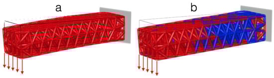
Figure 1.
(a) Response of the homogenous structure, and (b) evolved heterogenous structure for given equal loads and restraints. Red struts—stiff material, blue struts—soft material. The structure (b) is optimized for linear deflection.
The deflection lines considered in the paper range from simple ones such as straight line, to complexly composed ones including combinations of linear members, negative curvatures, step deflection, and fourth order polynomials, where locations of inflections and slopes are manipulated. These unintuitive responses have the potential to be used in different applications, i.e., ductility enhancements, fracture toughness, negative to zero thermal expansion, biomimetic materials, soft robotics, and functional materials [19,20,21,22]. Comparable concepts are also present in biological tissues, bones, plants, etc., where nature has produced a strategy to achieve unusual mechanical properties through coupling variable elastic moduli from a few GPa to below KPa [23].
The problem of finding material distribution to meet desired profile is formulated in optimization domain. A robust optimization algorithm is needed to reliably explore this domain. An evolutionary algorithm is developed and tested for the purpose in this study. Since the problem considered here has a vast search landscape, which is related to the number of struts in lattice and number of phases of materials used, a particular consideration in the development of the algorithm was dedicated to the genotype–phenotype mapping scheme since it is a time-consuming procedure.
It is necessary to find such an encoding that will allow the representation of the whole structure using a minimal number of parameters. The scheme should be simple, but allow for the representation of a desired level of details in the structure. It should also naturally promote evolvability of the population. For that reason, a generative encoding procedure was proposed, based on inverse Discrete Cosine Transform (DCT).
This procedure compresses the data necessary to describe complete structures at the arbitrarily fine resolution, and has some other favorable traits, such as natural symmetry promotion, which is important since it allows reduced calculation of error profiles, as explained in detail in Section 2.2.
The main contributions in this paper can be summarized as follows: (1) Proposing a method based on the Discrete Fourier Transform (DFT) for compressing the topological data of multi-material lattice structures, and reliable transformation from genotypic to phenotypic space and vice versa. This allows reduction of the convergence time in the evolutionary optimization domain. The method described in this study can be considered as a generalization of methods proposed to describe continuous topology in the frequency domain [24,25]. (2) Multi-material lattice domain space exploration by evolutionary algorithms allows optimization of the complete structures’ deformation behavior, as opposed to deformation performed in a single point.
The whole lattice structure with all attributes, including topology, elasticity constants, and shape, is uniquely mathematically described using connectivity and nodal matrices, is scalable in terms of including additional materials, and is suitable for manufacturing using additive manufacturing processes.
The remainder of the paper is organized as follows: the methods and algorithm outline are presented in Section 2 and Section 3. In Section 4, a number of 3D structures optimized to conform to deflection lines of different complexities are presented. Limitation of the structures based on material properties and complexity of deflection lines are discussed. In Section 5, discussion is given, and results are compared to similar existing approaches. Section 6 gives conclusions and insights in future research.
2. Method
2.1. Evolutionary Algorithms
Evolutionary algorithms belong to the family of population based heuristic optimization algorithms. These algorithms are inspired by some of the processes found in biological evolution, i.e., selection, mutation, and recombination. These mechanisms are used to evolve, or to artificially breed a solution for a typically hard optimization problem. The basic principle here is that individuals that form a population of potential solutions compete to survive. An individuals’ fitness, which is proportionate to its survival rate, is measured with the fitness function. Fitter individuals have a higher chance to survive and to pass their genetic material through crossover and mutation to the following generations.
Evolutionary algorithms, and other population-based algorithms, have been successfully applied to different problem domains. Nondeterministic polynomial time (NP) hard problems, large search spaces, constrained optimization problems with deceptive domains, among others, have all been successfully explored and optimized with evolutionary algorithms [26,27,28]. The disadvantages of evolutionary algorithms (EA)s compared to other optimization techniques lie in their stochastic nature. There is no formal guarantee of finding global optima. The quality of the solution depends on many factors, whose interconnections are highly nonlinear and stochastic in nature. Thus, finding a satisfactory combination of these parameters, i.e., population size, selection and surviving mechanism, probabilities of mutation and recombination, fitness scaling, genotype to phenotype mapping, etc., is very problem dependent and requires tedious experimental fine tuning to yield satisfactory results. Additionally, similarly to the biological process of evolution, the evolutionary algorithms might become slow for larger populations of individuals holding large information size in their genotype.
In this study, we propose a procedure based on generative encoding concept to compress the data contained in each individual, using a frequency matrix, and an inverse discrete cosine transform to make the mapping from genotype—this is a computational domain where crossover and mutation take place, to phenotype—this is the physical space where selection takes place. In our example, genotypic space consists of 3D frequency matrices where frequencies dictate material properties of struts, while phenotypic space consists of actual three-dimensional multi-material lattice structures subjected to loads and restraints.
2.2. Generative Encoding
It is worth describing encoding procedure in more detail. In generative encoding-based approaches, the information about the individual in the population are stored indirectly applying a set of rules. These rules are used to perform the transition of the individual from the phenotypic to genotypic space and vice versa. This can be considered a way of compressing the amount of data that describes the individual. The drawback of this approach is that there exists a computational overhead in applying these rules. Some examples of successfully applying generative encodings are generative grammar approaches, which were used to reduce the search space in evolving conceptual tensegrity structure deigns [29]. Compositional pattern-producing networks (CPPN) were used to optimize shape and material distribution of free-form objects [30]. Gaussian Mixtures (GMX) and its derivatives, based on level-set approaches, have been used to describe density fields and successfully applied to describe continuous soft-body robot systems [31].
In this study, we use a DCT approach to represent material distribution of the lattice structure. It is applied here for its simplicity and proven evolvability, and the ability to easily describe increasingly complex material distributions by including higher order harmonics. The distribution of material along a specific axis can be interpreted as a one-dimensional signal and treated as Fourier series. The usefulness of the Fourier analysis is that we can break up any arbitrary periodic function into a set of simple terms that can be solved individually and then recombined to reconstruct the original signal to a high degree of accuracy.
In the approach adopted in this paper, a phenotype of an individual is a 3D matrix composed of frequency amplitudes ranging from an arbitrarily chosen interval. Each amplitude is related to an adjacent harmonic, and the number of harmonics for each axis included in the phenotype limits the complexity of the design that can be reconstructed from the frequency matrix for that specific axis.
If there are N harmonics dedicated to the specific axis of the lattice design, there are potentially N regions along this axis, each describing a region of different mechanical properties of the structure. If we sum the numbers of all harmonics for all axes, we can define a metric called fineness of the structure:
where j is for all the harmonics associated with a particular axis, and i is for the number of axes considered: 1 is for 1D case, 2 is for 2D, and 3 is for a 3D case. The Discrete Cosine Transformation sums all weighted sinusoids and applies a threshold at a given value to define distinct regions of materials. This procedure is applied for each axis of the structure allowing the reconstruction of volumetric density field for the complete lattice structure.
The structure illustrated in Figure 2 is represented by summation of three weighted sinusoids to form a three-dimensional weighted space. The three sine waves have the following form:

Figure 2.
Generative representation of material distribution for truss structure using three weighted sinusoids.
This space is thresholded by the usage of inverse discrete cosine transformation. In the material distribution given above, the lattices belonging to regions above the threshold are defined as stiff and vice versa. This approach easily represents 3D topologies with arbitrarily detailed resolution of geometry in all three principal axes.
The one-dimensional Fourier cosine series on the interval [0, L] is given by:
with coefficients:
This representation is useful for even functions. Now, the discrete version of the Fourier cosine series can be derived by dividing the interval [0, L] into N equal segments. Let xi denote the midpoint of the ith segment and let fi denote f (xi). To avoid aliasing, the values of k are limited to be k = 0, 1, 2, …, N—1. The integral (4) is approximated by the midpoint quadrature rule, yielding:
which is, in some settings, known as Discrete Cosine Transform of Type II (DCT-II). This is the most used form and referred to as the DCT [32]. It is important to stress here that describing the structure using the approach presented in this study not only compresses the data required for representation of the structure, but also promotes symmetry of material deposited through the structure. This is exploited for the case of symmetrical loads and restraints analyzed in this study.
In general, to meet the targeted defection profile, at least four contours, each associated to one edge along the longest dimension, in our case, x1 of the structure, should be evaluated. This also holds for the case of symmetrical loads and restraints, but without promoting the symmetry through appropriate encoding. In the approach presented in this paper, all the deflection error calculations were performed only for one edge, which proved enough, as will be explained in the following sections.
Before rendering a multi-material lattice structure, it is necessary to check the position of the center of mass (cm) of each strut. The position of cm for the strut i in the 3D density matrix defines the property of the material of this strut, proportional to the material density field. This procedure must be repeated for each strut in the lattice structure. Despite that, the computational overhead in doing this is not excessively intensive, because the topology of the lattice stays fixed over time, since the nodes remain fixed and there is no variation of the length of the struts. For that reason, no iteration over the structure is necessary, a lookup table is designed in advance holding the information of cm and compared to mass distribution matrix.
2.3. Fitness Evaluation
Fitness function presents a central part of any evolutionary algorithm. This function is, in evolutionary context, an environment to which competing individuals must adapt. The ones that can make this adaptation better are fitter and have an increased chance to survive compared to the individuals that are less fit. In the example presented here, individuals must evolve a material distribution which enables them to achieve desired structural deformation.
To measure how a multi-material lattice structure deforms, the following is needed: a method to create the outer shape of the structure, a method to fill this shape with lattice structure, and a method to apply restraints, loads, and evaluate structural response.
As it concerns the first problem, outer geometry defined as a STEP model method is applied in this paper. STEP-file can support arbitrarily complex shapes, is free, easy to read, and recognized through the ISO-10303-21 standard. The outer geometry then is used to bound the lattice. The lattice itself is constructed using a standard tetrahedral mesh generator. In this study Gmsh generator [33] is used.
The output from the mesh generator consists of two matrices: connectivity matrix, later referred to as Conn.txt, and a nodal coordinate matrix, later referred to as Coord.txt. These two matrices are fed to the next step. In the next step, material and volume is associated with each strut. This enables the calculation of the response of the structure once loads are applied. The following step is to employ a multi-material physics simulator to evaluate structures’ response based on the distribution of the material, loads and restraints. Standard nonlinear finite element solvers are of limited applicability in situations including large deformations, instabilities, and significant differences between elastic moduli of struts [34]. Another problem is their computational time, which makes them impractical for implementation in population-based optimization algorithms. For that purpose, VoxCAD [35,36,37,38,39,40], a multi-material physics simulator is used. Voxelyze, the underlying engine running behind VoxCAD, is a computationally efficient simulation approach based on nonlinear relaxation of structural elements. Voxelyze simulates elastic voxels based on an internal lattice of discrete points, interconnected by spring like beam elements with translational and rotational stiffness. Once it is possible to calculate deformation of the structure subjected to loads, the optimization algorithm distributes the soft and stiff lattice struts throughout the structure, trying to minimize the deviation between the actual deflection profile, and the desired deflection profile. The outline of the optimization processes are illustrated in Figure 3.
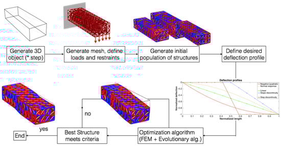
Figure 3.
The outline of the proposed optimization process.
To limit the search space size, the length of the cantilever beam is normalized and divided to thirteen equally spaced regions. For the problems presented in this study, this number proved to be a good balance between calculation time and ability of the structure to conform to given profiles. Finer discretization of the lattice comes at higher computational cost but would enable conforming to more complex geometries. On the other hand, a coarse discretization, with less elements, comes with increased rigidity, and thus limits the ability of the structure to conform to complex geometries. In each of these regions, the differences between the target and actual profiles are checked, and the summation of these differences defines so called root mean square error (RMSE), Equation (6), which is to be minimized. Individuals from the population with smaller RMSE values have a higher chance of being transferred to the population of parents, and to transfer their phenotypic material to the following generations.
3. Algorithm Details
A population of 60 individuals is subject to optimization until either the deviation of the best individual in the population, measured by RMSE, falls below a predefined threshold, or there is no significant fitness increase in the last 50% of the evaluations. RMSE, which is the objective function, is calculated as the difference between targeted deflection profile and current deflection profile of the structure, according to Equation (6):
N is for number of evaluated points along the deflection line. is a deviation vector to measure the difference between targeted and current profiles, as shown in Figure 4. As indicated in previous sections, due to promotion of symmetrical load distribution through presented encoding procedures, it is enough to evaluate only one contour for RMSE minimization. In the case of symmetrical structures and loads, this suffices. For more complex distributions of loads and restraints, a minimum of two or even more profiles should be associated to the contours of the structure and included in RMSE calculation.

Figure 4.
Difference between the optimized multi-material and unoptimized single material structures for RMSE minimization.
To evaluate a population and find those individuals fitter than others, a tournament selection scheme was used. Five individuals were randomly chosen from the population. The two fittest members of the five produced two children. A weight associated to the Fourier series defining material distribution was randomly selected from one and added to the other parent to create offspring. After the new population of 60 individuals was created, the mutation operator was applied.
Mutation was used to randomly change a small part of an individual and thus ensure diversity in the genetic pool and connectivity of the search space.
A randomly chosen weight of an individual was changed by 2%. In one individual, at most, 10% of weights can change through mutation.
4. Results
In this section, results of the proposed evolutionary algorithm for multi-material lattice structures are presented. So far, the structures are optimized to follow a predefined response, deflection after the load is applied. In all the cases illustrated in Figure 5, the left surface is clamped, the right one is free. The load was applied on the latter surface, and the bottom edge. Four cases are presented here: linear, quadratic, step, and slope discontinuity. All the deformations were multiplied ten times for the purpose of illustration. Red struts correspond to stiff material, while blue struts were for soft material. By deposition of soft and stiff struts, it was possible to evolve structures that follow given deformation behaviors with a small error. In all the results presented, the lattice consisted of 731 struts. There were no constraints on the distribution of soft and stiff materials in the lattice, although these could be easily implemented. All the structures were evolved for five thousand generations. For the case (a) linear deformation response, the algorithm showed favorable results for this problem, being able to minimize RMSE below 10−3 within 2000 iterations. Case (b) showed that the deflection line was constructed to have a zero slope both on the clamped and the free edge.
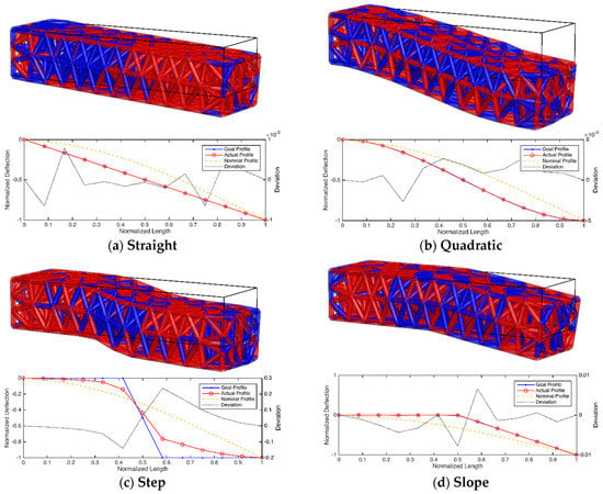
Figure 5.
Evolved structures for different deflection profiles, with goal, actual, and normal profiles and deviation between target and actual profiles.
Additionally, inflection point was enforced in the midpoint of the structure in the direction of the longest axis. To meet these criteria, we assume the deflection line is a fourth order polynomial of the form:
With following boundary conditions:
then the deflection line takes following form:
The polynomial order is 3, which is the same as for the homogenous case, but boundary conditions are satisfied.
If we move the x location of second derivative equals zero condition away from x = 0.5, the deflection line takes the general fourth order polynomial form. The algorithm performed well on this problem, being able to reduce RMSE to approximately 5e10−3 within 5000 iterations. Case (c) was for the step function, which proved to be hard to satisfy, especially in the region where discontinuities were located.
To minimize deflection error in this case, significant differences between elastic moduli between the two phases are required, as discussed later. Here, we have larger RMSE, approximately 2.5e10−1 at the end, compared to the previous two cases. The last case, (d), presents the slope discontinuity, which is composed of two piecewise linear functions. The algorithm yields quality results, with the RMSE values at 10−2 found around the discontinuity of the profile.
A typical optimization cycle of the structure is shown in Figure 6. Three phases are presented: at the beginning of the optimization, at 50% of total iterations number, and the final structure. The structure presented was optimized for negative curvature. This type of curvature is difficult to achieve, which is illustrated with the error plot. The error plot shows that difference between target and achieved is spread thorough whole structure.

Figure 6.
Evolution of the structure optimized for negative quadratic curvature: (a) initial stage, (b) 2500 generations, and (c) at 5000 generations. Top right is the goal profile along with actual, nominal, and error plots for the final structure.
The ratio between elastic moduli of stiff and soft struts is an important parameter, and it bounds the minimal RMSE the structure can achieve for the given total number of struts. This is illustrated in Figure 7. Parameter ξ is defined as: .

Figure 7.
RMSE relation to different elastic moduli ratio , for negative quadratic (S1) and step discontinuity specimens (S2).
The error plots were obtained by running the algorithm 50 times for a particular deflection profile. Two specimens were compared here: negative quadratic deflection profile (Specimen S1) and step discontinuity profile (Specimen S2).
It is obvious that step discontinuity minimizes the residual RMSE better with increase of ξ. Whereas negative quadratic profile has a sweet spot at ξ =100, and with further increase of ξ, the residual error increases. That means that there is no general rule about the nature of relation between error minimization and elastic moduli difference.
We analyzed hypothetical minimal values for ξ which will allow the desired structural deformation behaviors. We found that for simpler scenarios, i.e., linear response, and to minimize RMSE to acceptable level, and for most complex desired deformation profiles. We found that is enough to minimize RMSE to acceptable level in case of simple deflection profiles, i.e. linear target deformation. For most complex cases, i.e. step discontinuity, a significantly larger difference in elastic moduli, is required.
It is important to stress that, in theory, significant differences between elastic moduli, as high as 3000 times, are possible at the present state of the art 3D printing technology [15]. In addition to the parameter ξ, the number of lattice struts plays a role in RMSE minimization. The drawback of increasing this number is the computational cost that comes with it. The number of 731 struts used in the paper showed to be a good compromise between the quality of solutions and computational time. Fundamentally, this number does not give new qualitative insight, it is favorable to have a finer lattice compared to more coarse structures if the calculation time is not a limiting factor.
5. Discussion
Heterogeneity of material distribution in lattice structures was exploited to enable conforming of lattice to a set of predefined shapes. It was shown that by combining different elastic moduli, it was possible to achieve a range of predefined geometries with various complexities. Existing approaches dealing with design of functional, lattice-based materials deal with auxetics [14], optimality criteria for mass minimization [15], and design of a complex data-driven process for volume deformation control [41].
Other important findings have been made in the field of simulation tools designed for deformation analysis of lattice structures [34]. In the case of auxetic materials, careful orientation of the base units is needed to produce a handed structure with desired properties. Most of the work in auxetics deals with 2D problems. In the case of 3D structures, motions such as bending, twisting, or linear extension are considered. Recent works in 3D lattice optimization consider a grading approach to increase yield strength and stiffness of the structure through manipulation of shape and size of the struts [18].
In this study, the goal is to exploit the trait of different elastic moduli to enable conforming of the lattice structure to different 3D structures once load is applied. This approach is motivated by the current state of the art of 3D multi-material technology, which enables simultaneous printing of different material phases. The proposed population algorithm can explore the search space and evolve complex multi-material structures that deform to the predefined geometry once external forces are applied. This is not easily achieved by manually designing structures using conventional CAD techniques, or using standard topological optimization approaches, such as homogenization or shape optimization. It was pointed out that the crucial parameter for success of optimization is the ratio between the elastic moduli of stiff and soft materials, .
The dependency between this parameter and residual error is neither linear nor proportionate. For some cases, residual error decreases with increase of only up to a certain point, after which the structure cannot use the heterogeneity of materials as a source of further decreasing the residual error. For , the optimization cannot be performed, considering the problems presented in this paper and the methods used.
A procedure based on discrete cosine transform was proposed for data compression of the topology of truss structures. This increases the speed of the convergence, but also symmetry is naturally promoted in the structures. This is a favorable trait for the case of symmetrically loaded structures, and desired symmetrical deformation behaviors.
6. Conclusions and Future Work
The method presented in this study proved suitable for solving the problem of finding material distribution of lattices’ struts with the goal of achieving desired deformation behaviors. Despite proven reliability of the used numerical simulation environment, additional analyses through both numerical and experimental validation are necessary to reliably describe the hyperelastic nature of printed structures.
The future work will include additional optimization criteria, i.e., mass minimization in addition to fulfilling deformation criteria. Another interesting problem will be to enable simultaneous shape optimization. In addition, variable lattices will be incorporated, which will affect the rigidity/compliance of the structure in certain regions, based on the structure of the lattice in that domain. The last step would be to manufacture specimens and experimentally confirm results obtained through simulations.
Funding
This research was supported by Fulbright postdoctoral research grant Maximum Mobility of Robots Based on Co-evolutionary Algorithms.
Institutional Review Board Statement
Not applicable.
Data Availability Statement
Not applicable.
Conflicts of Interest
The author declares no conflict of interest.
References
- Rus, D.L.; Tolley, M.T. Design, fabrication and control of soft robots. Nature 2015, 521, 467–475. [Google Scholar] [CrossRef] [PubMed]
- Li, S.; Rus, D. JelloCube: A Continuously Jumping Robot with Soft Body. IEEE/ASME Trans. Mechatron. 2019, 24, 447–458. [Google Scholar] [CrossRef]
- Lipson, H.; Kurman, M. Fabricated: The New World of 3D Printing; Wiley: New York, NY, USA, 2013. [Google Scholar]
- Bendsoe, M.P.; Noboru, K. Generating optimal topologies in structural design using a homogenization method. Comput. Methods Appl. Mech. Eng. 1988, 71, 197–224. [Google Scholar] [CrossRef]
- Cotelo, J.; Das, S.; Castañeda, P.P. A differential homogenization method for estimating the macroscopic response and field statistics of particulate viscoelastic composites. Int. J. Solids Struct. 2020, 204, 199–219. [Google Scholar] [CrossRef]
- Zhang, H.; Kumar, A.S.; Fuh, J.Y.H.; Wang, M.Y. Topology optimized design, fabrication and evaluation of a multimaterial soft gripper. In Proceedings of the 2018 IEEE International Conference on Soft Robotics (RoboSoft), Livorno, Italy, 24–28 April 2018; pp. 424–430. [Google Scholar]
- Wang, N.; Hu, K.; Zhang, X.M. Hierarchical optimization for topology design of multi-material compliant mechanisms. Eng. Optim. 2017, 49, 2013–2035. [Google Scholar] [CrossRef]
- Chu, S.; Gao, L.; Xiao, M.; Luo, Z.; Li, H. Stress-based multi-material topology optimization of compliant mechanisms. Int. J. Numer. Methods Eng. 2017, 113, 1021–1044. [Google Scholar] [CrossRef]
- Zhu, B.; Zhang, X.; Zhang, H.; Liang, J.; Zang, H.; Li, H.; Wang, R. Design of compliant mechanisms using continuum topology optimization: A review. Mech. Mach. Theory 2020, 143, 103622. [Google Scholar] [CrossRef]
- Hiller, J.; Lipson, H. Rapid manufacturing of digital materials. In Proceedings of the Rapid Manufacturing Conference, Loughborough, UK, 8–9 July 2009. [Google Scholar]
- Cheng, G. Some aspects of truss topology optimization. Struct. Optim. 1995, 10, 173–179. [Google Scholar] [CrossRef]
- Cao, H.; Qian, X.; Chen, Z.; Zhu, H. Enhanced particle swarm optimization for size and shape optimization of truss structures. Eng. Optim. 2017, 49, 1939–1956. [Google Scholar] [CrossRef]
- Millan-Paramo, C.; Filho, J.E.A. Size and Shape Optimization of Truss Structures with Natural Frequency Constraints Using Modified Simulated Annealing Algorithm. Arab. J. Sci. Eng. 2020, 45, 3511–3525. [Google Scholar] [CrossRef]
- Lipton, J.I.; MacCurdy, R.; Manchester, Z.; Chin, L.; Cellucci, D.; Rus, D. Handedness in shearing auxetics creates rigid and compliant structures. Science 2018, 360, 632–635. [Google Scholar] [CrossRef] [PubMed]
- Stanković, T.; Mueller, J.; Egan, P.F.; Shea, K. A Generalized Optimality Criteria Method for Optimization of Additively Manufactured Multimaterial Lattice Structures. J. Mech. Des. 2015, 137, 111405. [Google Scholar] [CrossRef]
- Kazemi, H.; Vaziri, A.; Norato, J.A. Multi-material topology optimization of lattice structures using geometry projection. Comput. Methods Appl. Mech. Eng. 2020, 363, 112895. [Google Scholar] [CrossRef]
- Fan, Z.; Yan, J.; Wallin, M.; Ristinmaa, M.; Niu, B.; Zhao, G. Multiscale eigenfrequency optimization of multimaterial lattice structures based on the asymptotic homogenization method. Struct. Multidiscip. Optim. 2020, 61, 983–998. [Google Scholar] [CrossRef]
- Dong, G.; Tang, Y.; Li, D.; Zhao, Y.F. Design and optimization of solid lattice hybrid structures fabricated by T additive manufacturing. Addit. Manuf. 2020, 33. [Google Scholar] [CrossRef]
- Wu, L.; Lingling, W.; Zhou, J. Isotropic Negative Thermal Expansion Metamaterials. ACS Appl. Mater. Interfaces 2016, 8, 17721–17727. [Google Scholar] [CrossRef]
- Lakes, R. Cellular solids with tunable positive or negative thermal expansion of unbounded magnitude. Appl. Phys. Lett. 2007, 90, 221905. [Google Scholar] [CrossRef]
- Curkovic, P.; Jambrecic, A. Improving Structural Design of Soft Actuators Using Finite Element Method Analysis. Interdiscip. Descr. Complex Syst. 2020, 18, 490–500. [Google Scholar] [CrossRef]
- Gao, T.; Zhang, W. A new methodology for thermostructural topology optimization: Analytical definition and validation. Proc. Inst. Mech. Eng. Part L J. Mater. Des. Appl. 2020. [Google Scholar] [CrossRef]
- Chen, D.; Zhen, X. Multi-Material Additive Manufacturing of Metamaterials with Giant, Tailorable Negative Poisson’s Ratios. Sci. Rep. 2018, 8, 9139. [Google Scholar] [CrossRef] [PubMed]
- Hiller, J.; Lipson, H. Design Automation for Multi-Material Printing. In Proceedings of the 20th Annual International Solid Freeform Fabrication Symposium, Austin, TX, USA, 3–5 August 2009. [Google Scholar]
- White, D.A.; Stowell, M.L.; Tortorelli, D.A. Toplogical optimization of structures using Fourier representations. Struct. Multidiscip. Optim. 2018, 58, 1205–1220. [Google Scholar] [CrossRef]
- Curkovic, P.; Čehulić, L. Diversity Maintenance for Efficient Robot Path Planning. Appl. Sci. 2020, 10, 1721. [Google Scholar] [CrossRef]
- Eiben, A.E.; Smith, J.E. Introduction to Evolutionary Computing; Springer: Cham, Switzerland, 2003. [Google Scholar]
- Curkovic, P.; Jerbic, B.; Stipancic, T. Coordination of Robots with Overlapping Workspaces Based on Motion Co-Evolution. Int. J. Simul. Model. 2013, 12, 27–38. [Google Scholar] [CrossRef]
- Rieffel, J.; Valero-Cuevas, F.; Lipson, H. Automated discovery and optimization of large irregular tensegrity structures. Comput. Struct. 2009, 87, 368–379. [Google Scholar] [CrossRef]
- Evins, R.; Vaidyanathan, R.; Burgess, S. Multi-Material Compositional Pattern-Producing Networks for Form Optimisation. In Applications of Evolutionary Computation. EvoApplications 2014; Lecture Notes in Computer Science; Springer: Berlin/Heidelberg, Germany, 2014. [Google Scholar]
- Hiller, J.; Lipson, H. Automatic Design and Manufacture of Soft Robots. IEEE Trans. Robot. 2011, 28, 457–466. [Google Scholar] [CrossRef]
- Yaroslavsky, L.P. Image Recovery from Sparse Samples, Discrete Sampling Theorem, and Sharply Bounded Band-Limited Discrete Signals. Adv. Imaging Electron Phys. 2011, 167, 295–331. [Google Scholar] [CrossRef]
- Geuzaine, C.; Remacle, J.F. Gmsh: A three-dimensional finite element mesh generator with built-in pre- and post-processing facilities. Int. J. Numer. Methods Eng. 2009, 79, 1309–1331. [Google Scholar] [CrossRef]
- Weeger, O.; Boddeti, N.; Yeung, S.-K.; Kaijima, S.; Dunn, M. Digital design and nonlinear simulation for additive manufacturing of soft lattice structures. Addit. Manuf. 2019, 25, 39–49. [Google Scholar] [CrossRef]
- Hilller, J.; Lipson, H. Dynamic Simulation of Soft Multimaterial 3D-Printed Objects. Soft Robot. 2014, 1, 88–101. [Google Scholar] [CrossRef]
- VoxCAD. Available online: https://sites.google.com/site/voxcadproject/ (accessed on 12 January 2021).
- Sui, X.; Cai, H.; Bie, D.; Zhang, Y.; Zhao, J.; Zhu, Y. Automatic Generation of Locomotion Patterns for Soft Modular Reconfigurable Robots. Appl. Sci. 2019, 10, 294. [Google Scholar] [CrossRef]
- Gu, Y.; Zhang, X.; Wu, Q.; Li, B.; Gao, F.; Luo, Y. Research on Motion Evolution of Soft Robot Based on VoxCAD. In Intelligent Robotics and Applications; Yu, H., Liu, J., Liu, L., Ju, Z., Liu, Y., Zhou, D., Eds.; Lecture Notes in Computer Science; ICIRA: Shenyang, China, 2019. [Google Scholar]
- Methenitis, G.; Hennes, D.; Izzo, D.; Visser, A. Novelty Search for Soft Robotic Space Exploration. In Proceedings of the 2015 Annual Conference on Genetic and Evolutionary, GECCO’15, Madrid, Spain, 11–15 July 2015. [Google Scholar]
- Kriegman, S.; Cappelle, C.; Corucci, F.; Bernatskiy, A.; Cheney, N.; Bongard, J.C. Simulating the Evolution of Soft and Rigid-Body Robots. In Proceedings of the GECCO’17 Companion, Berlin/Heidelberg, Germany, 15–19 July 2017. [Google Scholar]
- Bickel, B.; Bächer, M.; Otaduy, M.A.; Lee, H.R.; Pfister, H.; Gross, M.; Matusik, W. Design and fabrication of materials with desired deformation behavior. ACM Trans. Graph. 2010, 29, 1–10. [Google Scholar] [CrossRef]


Publisher’s Note: MDPI stays neutral with regard to jurisdictional claims in published maps and institutional affiliations. |
© 2021 by the author. Licensee MDPI, Basel, Switzerland. This article is an open access article distributed under the terms and conditions of the Creative Commons Attribution (CC BY) license (http://creativecommons.org/licenses/by/4.0/).