Article

Research on Segmented Primary Consequent-Pole Permanent Magnet Linear Synchronous Motor with Symmetric and Periodic End Force

Department of Electrical Engineering, Nanjing University of Aeronautics and Astronautics, Nanjing 210016, China
*
Author to whom correspondence should be addressed.
Symmetry 2021, 13(12), 2374; https://doi.org/10.3390/sym13122374
Submission received: 21 October 2021 / Revised: 19 November 2021 / Accepted: 22 November 2021 / Published: 9 December 2021
(This article belongs to the Section Computer)

Abstract

:
The end force of North-South permanent magnet linear synchronous motor (NS-PMLSM) fluctuates symmetrically with a period of one pole. Different from it, the end force’s fluctuation cycle of the consequent-pole permanent magnet linear synchronous motor (CP-PMLSM) is usually two poles and asymmetrical. Especially, within two half cycles, the end force presents complex asymmetric characteristics. In this paper, a piecewise function model of the end force of CP-PMLSM is established. Then a primary segmented design method for adjusting the period, symmetry and phase of the end force waveform is proposed. The two-segment and grouped four-segment modular distances are combined and matched to eliminate the odd-numbered harmonics of the end force and suppress the thrust ripple. A slotless primary core experimental platform and a slotted CP-PMLSM prototype are manufactured and tested to verify the theoretical analysis and simulation results.

1. Introduction

The demand for permanent magnet linear synchronous motor (PMLSM) has increased in logistics transportation and automated production. However, the global shortage of permanent magnet materials and unstable supply make the cost of the motor high, which restricts the development of the PMLSM [1]. How to reduce the cost has become a focus of the research on PMLSM. Compared with traditional North-South (NS) motors, consequent-pole (CP) motors employ a part of iron poles (IPs) instead of permanent magnets (PMs). IP and PM are alternately arranged for excitation. This structure has been applied to both rotary motor [2,3,4,5,6,7,8,9,10,11,12,13] and linear motor [14,15,16,17,18,19,20].
In addition to reducing costs, CP structure may have the following advantages: Compared with conventional surface-mounted NS motor with stainless steel sleeves, CP motor is beneficial to reducing the total iron loss and PM loss, thereby reducing rotor temperature and improving motor efficiency [2,3]. Compared with the conventional surface-mounted PM motor with 4-pole/6-slot combination, the proposed CP flux reversal PM motor with 16-pole/6-slot combination outputs 1.38 times higher torque. Its PM utilization rate is much higher with the torque per PM volume increasing by 2.8 times. Moreover, its flux weakening capability is much better than the conventional one [4]. In [5], the proposed CP flux reversal PM machine topology adopting Halbach array magnets shows higher back-electromotive force (back-EMF), torque density, and magnetic flux utilization. The leakage flux can be reduced effectively by the Halbach array magnets, which are placed in the rotor slot top and can guide the flux into the rotor teeth. In [6], the proposed dual-CP transverse flux motor increases the space utilization and torque density. Its stator and rotor all adopt CP structure.
However, the CP motor has the following shortcomings. The asymmetric air-gap flux density results in even-numbered back-EMF harmonics, bigger torque ripple, severe end magnetization, as well as unbalanced magnetic tension. In order to overcome these shortcomings, slot/pole combination [7,8], multilayer windings or equal-pole-arc magnetic pole [9], and asymmetric magnetic pole structure [10] can be used to reduce or eliminate even-numbered back-EMF harmonics. The torque or thrust ripple can be suppressed by modular structure, eccentric shape PMs, skewed poles, and non-uniform air gap [11]. In [12], in order to improve the unbalanced magnetic flux, the improved CP structure of “N-S-IP-S-N-IP” is employed. It is helpful to reduce the stator yoke saturation and increase the torque density and efficiency as well [12]. In [13], the utilization of rare earth PM materials is enhanced by obtaining the best PM-arc ratio.
For the linear motors, in addition to the above methods, response surface method combined with finite element analysis was employed for obtaining greater output capability and quality of Halbach CP-PMLSM through the optimization of pole parameters. In [14], the proposed topology of double-sided shifting one pole pitch can offset magnetic unbalance, which is beneficial to suppress the thrust ripple. In [15], in order to get the flux linkage, induced EMF and average thrust, the surface-mounted and CP linear vernier hybrid motor shows an analytical method which can model the no-load air-gap flux density. In [16], the leakage flux could be suppressed by the novel dual-CP transverse flux linear topology. Because of the dual-PM structure, the coil flux linkage and the force density are much higher without increasing the occupied volume. In [17,18,19,20], Shi-UK Chung built a variety of modular models of CP-PMLSM and set the distance between each primary core to achieve the suppression of the thrust fluctuation.
The above research has laid a good foundation for the optimization of the CP-PMLSM. However, the accurate end force model of the CP-PMLSM has not been established, nor has the end force characteristics been analyzed in detail. The cogging force and the end force are coupled together. This exacerbates the complexity of CP-PMLSM’s detent force.
This paper adopts CP structure instead of NS structure for PMLSM to save the PMs amount, thereby reducing the machining cost of the motor with long secondary. However, the fluctuation characteristics of the CP-PMLSM’s end force are different from traditional NS-PMLSMs, which is complex to analyze and difficult to suppress. The end force models and suppression methods in previous studies are not well-suited to CP-PMLSM, so this paper focuses on establishing an accurate model of CP-PMLSM’s end force, clarifying its periodic and asymmetric characteristics, and proposing a primary segmented design method. The main contents include: In Section 2, the simplified magnetic circuits describe the difference of air-gap flux between the NS-PMLSM and CP-PMLSM. The pulsating magnetic field of the CP-PMLSM is analyzed, which is the source of the end force. The magnetic flux function through the primary end of CP-PMLSM is established. Based on this, the characteristic of the end force is clarified and the piecewise function model is established. Section 3 proposes a two-segment classification method to adjust the period and symmetry of the end force. The experimental verification is carried out on a slotless primary core experimental platform. Section 4 proposes a grouped four-segment method to realize the anti-phase cancellation of the end forces between the groups and eliminate a large number of odd-numbered harmonics. The two-segment and four-segment modularizations are matched. One slotted CP-PMLSM prototype has been manufactured. The finite element (FEM) and experimental results verify the versatility and effectiveness of the method. The conclusions are drawn in Section 5.

2. End Force Model of CP-PMLSM

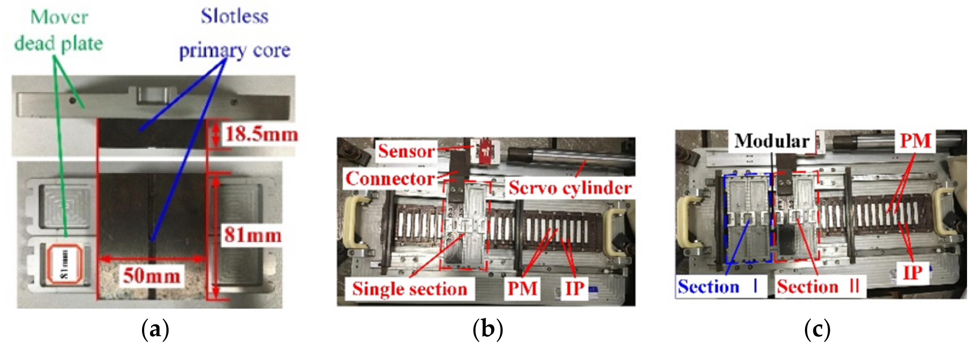
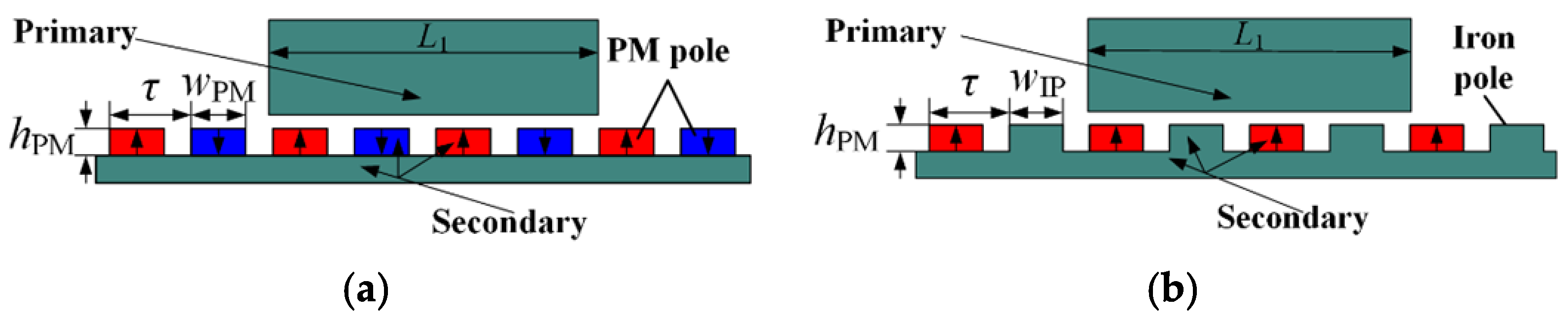
2.1. Structure of CP-PMLSM

Figure 1 shows the structures of the NS-PMLSM and CP-PMLSM with slotless structure. The difference between them is reflected in the secondary structures. The PMs of the NS-PMLSM have N and S poles. They are alternately arranged to form a pair of poles. CP-PMLSM adopts PMs with single polarity and IPs alternately arranged. Iron poles and secondary back yoke are integrated with the same material. Obviously, the secondary structure of CP-PMLSM can effectively reduce the amount of PMs and machining cost, especially in the application of long secondary and long stroke.
The NS-PMLSM’s and CP-PMLSM’s magnetic circuits are drawn in Figure 2, which are simplified by neglecting the leakage flux. Fm, Rm, and Rg are the PM magneto motive force, PM reluctance and air-gap reluctance respectively. Rpc, Rsc, and RIP represent the reluctances of the primary core, secondary core, and IP respectively, which can be neglected for further simplifying the magnetic circuit. As shown in Figure 2a, Φ1 and Φ2 represent the air-gap flux above PM in the NS-PMLSM. As shown in Figure 2b, Φ1′ represents the air-gap flux above PM in the CP-PMLSM, and Φ2′ represents the air-gap flux above IP in the CP-PMLSM.
Based on the simplified magnetic circuit in Figure 2a, Φ1, and Φ2 can be obtained as follows:
ϕ 1 = ϕ 2 = F m R m + R g
Similarly, Φ1′ and Φ2′ in Figure 2b can be expressed as follows:
ϕ 1 = ϕ 2 = F m R m + 2 R g
From Equations (1) and (2), the air-gap flux in NS-PMLSM is larger than that in CP-PMLSM. Therefore, for these two kinds of motors of the same size, the thrust of CP-PMLSM is smaller. Table 1 lists the parameters of the NS-PMLSM I and two kinds of CP-PMLSMs. The parameters of the NS-PMLSM I and CP-PMLSM I are the same. For the CP-PMLSM I, the geometrical parameters of the PM and IP poles are the same, wPM = wIP. For the CP-PMLSM II, the widths of the PM and IP poles are different, wPMwIP. With the same primary parameters, the CP-PMLSM I can output 75% of the NS-PMLSM I’s thrust by using 50% PMs, whereas the CP-PMLSM II can output the same thrust of the NS-PMLSM by just using 80% PMs.
Comparing the ratio of thrust to PM volume (fr = F/VPM) of NS-PMLSM I and CP-PMLSM I, as shown in Figure 3, as the VPM increases, the coefficient fr of the NS-PMLSM and CP-PMLSM decrease, and the coefficient fr of NS-PMLSM ranges from 2.485 N/cm3 to 5.026 N/cm3, whereas the fr of the CP-PMLSM changes from 3.893 N/cm3 to 7.470 N/cm3. With the same PM parameters, the value of fr of the CP-PMLSM is about 1.5 times that of the NS-PMLSM. All parameters of CP-PMLSM II listed in Table 1 have been optimized to obtain the same thrust as the NS-PMLSM, and its fr is 4.873 N/cm3.

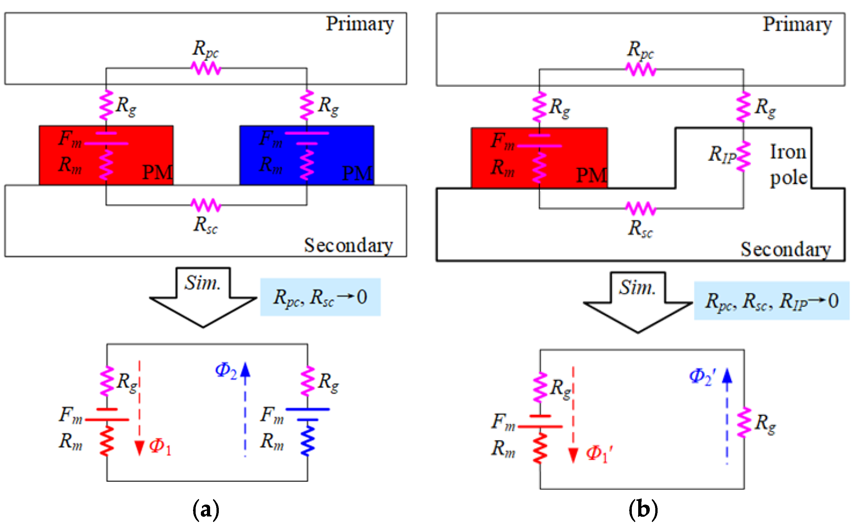
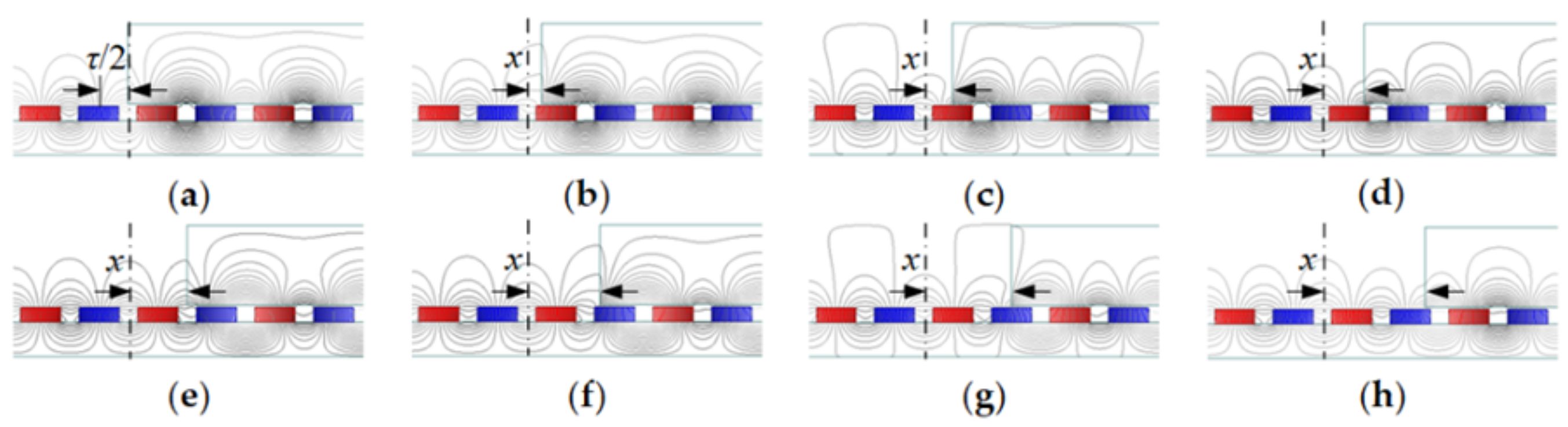
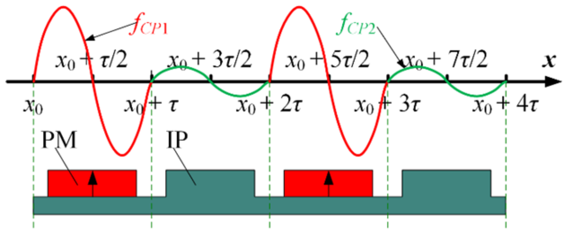
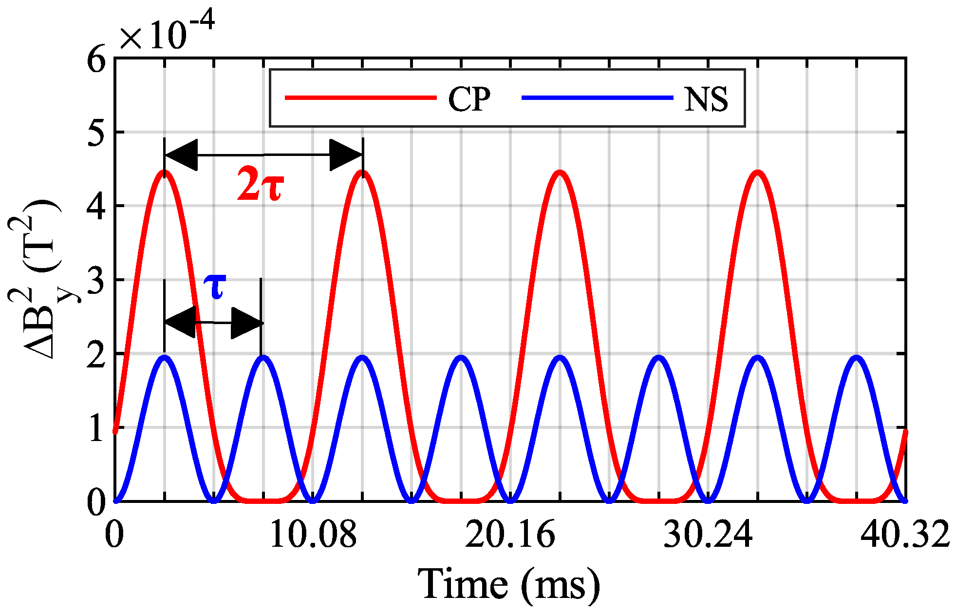
2.2. Characteristics of Pulsating Magnetic Fields

The alternating arrangement of PMs and IPs of the CP-PMLSM causes the air-gap flux density distribution to be different from that of the NS-PMLSM. The FEM models shown in Figure 4 are established to obtain the air-gap flux density of the CP-PMLSM I. Besides, the end effect generates a pulsating magnetic field, which results in the end force and can be calculated by the different boundary condition models [21]. The FEM models of the NS-PMLSM I are established based on the same principle. The primary and secondary act as stator and mover respectively. The primary employs a slotless structure to eliminate the influence of the slot effect. In Figure 4a, the master-slave boundary is used to eliminate the influence of the end effect. In Figure 4b, the whole motor model with the conventional vector magnetic potential boundary can consider the end effect. It is assumed that the air-gap flux density in Figure 4a,b are By0(x) and By(x), respectively.
The magnetic field variation in the air gap caused by the end effect is the pulsating magnetic field, which can be expressed as
Δ B y x = B y x B y 0 x
where x is the relative position between the primary and the secondary; By(x) is the air-gap flux density with end effect; By0(x) is the air-gap flux density without end effect, and ΔBy(x) is the pulsating magnetic field.
At the initial time, By0, By, and ΔBy of the CP-PMLSM and NS-PMLSM are obtained by FEM, as shown in Figure 5. By0 and By of the NS-PMLSM coincide with each other basically, and ΔBy is a direct current (DC) component whose value is almost to 0. However, By0 and By of the CP-PMLSM do not coincide, which reflects that the value of ΔBy is not 0. Therefore, the change law of ΔBy of different pole structure is different even under the same FEM simulation conditions. The reason for this difference is that the effect of pulsating magnetic field caused by end effect on different pole structure is different.
Figure 6a,c show the curves of ΔBy at different times of CP-PMLSM and NS-PMLSM respectively. These several ΔBy curves of NS-PMLSM are all approximately horizontal, whereas the ΔBy curves of CP-PMLSM fluctuate around horizontal lines. With the change of time, the average values of ΔBy change periodically, as shown in Figure 6b. The rated speed of the mover is 2 m/s. The time it takes the mover to run a pair of poles is 10.08 ms. It is obvious that the curves of average values of ΔBy vary sinusoidally by the period of 10.08 ms. The curve of the NS-PMLSM goes up and down around 0, whereas the curve of the CP-PMLSM is in the negative half axis which has a DC offset.
According to the principle of energy conversion, the end force of the motor can be calculated by
f e d = 1 2 μ 0 x V Δ B y 2 d V
where μ0 is the vacuum permeability and V is the volume of the equivalent air gap.
Figure 7 shows the square of average values of ΔByBy2) varying with time. The periods of ΔBy2 of the PMLSMs with different pole structures are different, which indirectly reflects the fluctuation law of the end force of the CP-PMLSM and NS-PMLSM. The end-force’s period of the NS-PMLSM is τ, whereas that of the CP-PMLSM is 2τ. The difference above calls for a new accurate model of CP-PMLSM’s end force to clarify its period and asymmetric characteristics.

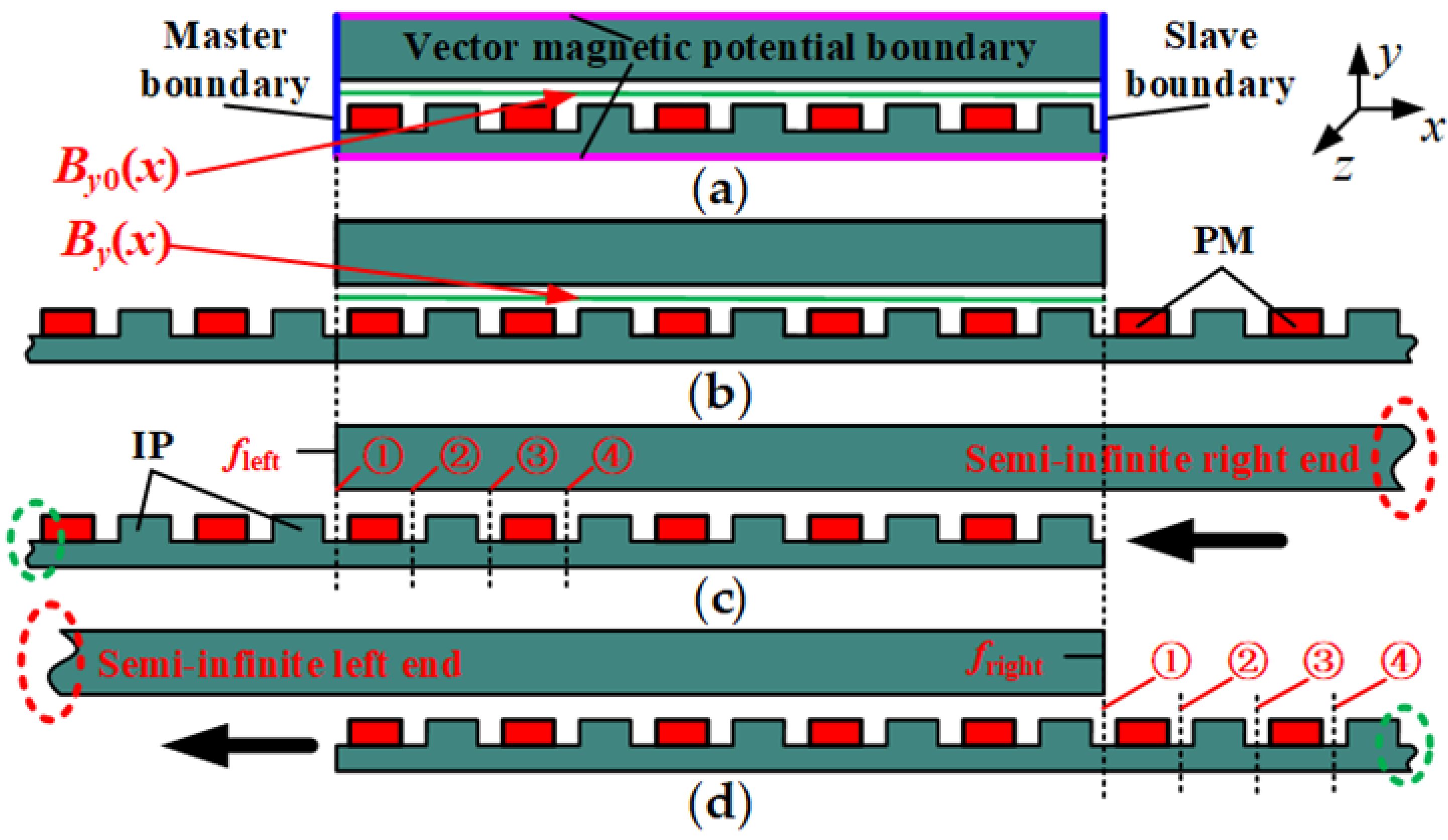
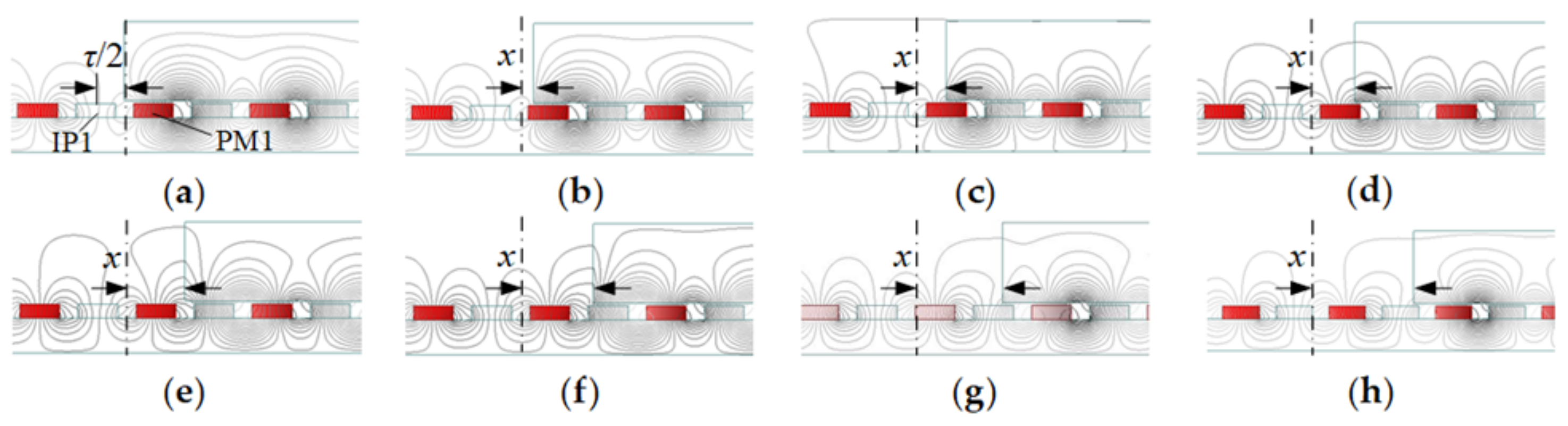
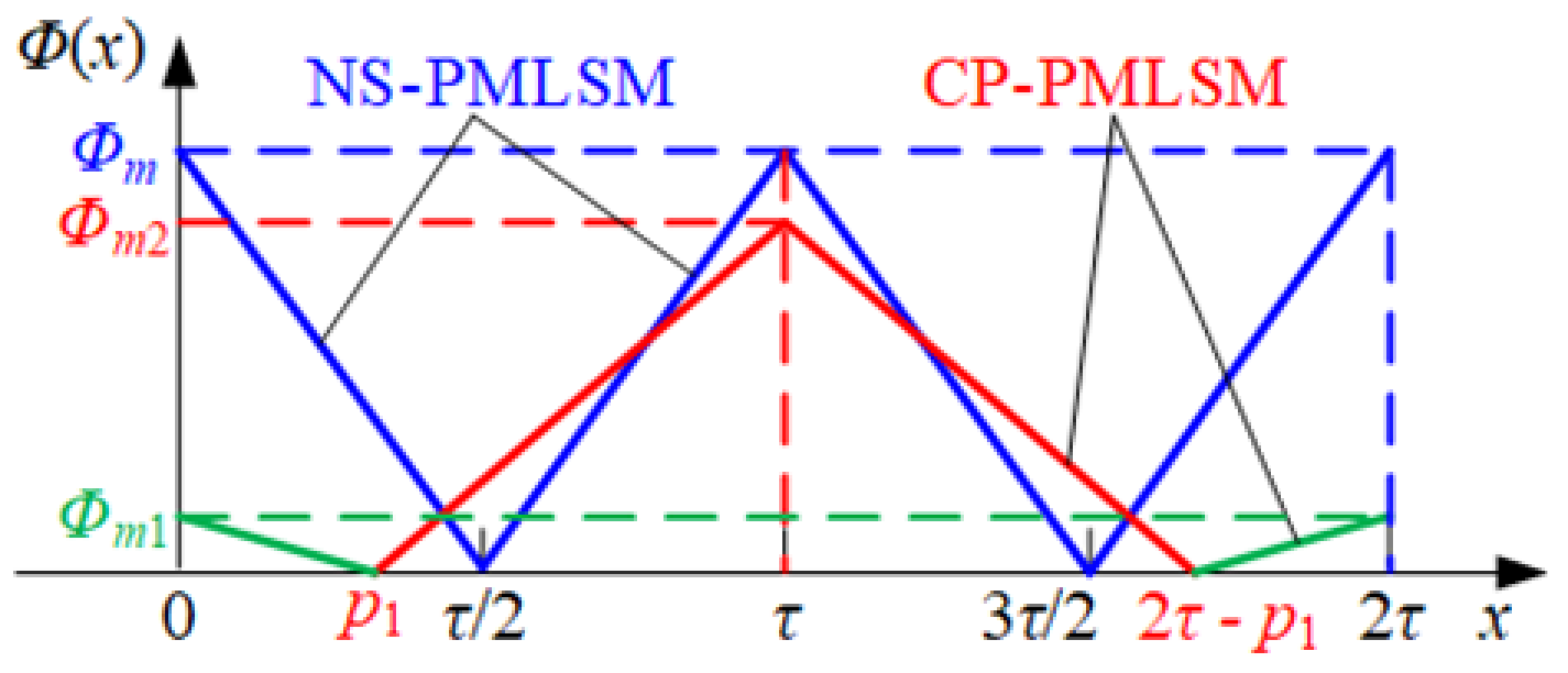
2.3. Modeling of CP-PMLSM’s Magnetic Flux Function through the Primary End

Figure 8 and Figure 9 show the magnetic flux function through the primary end in the range of 2τ of NS-PMLSM and CP-PMLSM. The magnetic flux across the longitudinal end of the primary armature core varies with the position of the mover. At x = 0 in Figure 8a, the magnetic flux passing through the left end of the primary armature core reaches its maximum value Φm, that is, Φ(0) = Φm. As the mover runs, the magnetic flux passing through the end becomes less and less. When it reaches the position x = τ/2 in Figure 8c, the magnetic flux passing through the left end is zero, that is, Φ(τ/2) = 0. As the primary continues to move, the magnetic flux across the left end becomes larger and larger. When running at x = τ in Figure 8e, the magnetic flux across the left end becomes maximum again, Φ(τ) = Φm. The above periodic change is then repeated. The magnetic flux function at the left end of the primary armature core has a period of one pole pitch (τ). However, the magnetic flux variation of CP-PMLSM is different from that of NS-PMLSM. At x = 0 in Figure 9a, the iron pole (IP1) does not actively excite, and the magnetic flux generated by the PM (PM1) forms a magnetic loop with IP1 through the primary left end. At this time, the magnetic flux is Φ(0) = Φm1. As the mover runs, less and less magnetic flux passes through the end, and the magnetic flux is Φ(p1) = 0 in Figure 9b. The primary continues to move, and the magnetic flux passing through the left end becomes larger and larger until x = τ reaches its maximum value in Figure 9e, Φ(τ) = Φm2. The primary continues, and the magnetic flux across the end decreases to zero (Figure 9g) and then increases gradually until the relative position in Figure 9a reaches Φm1. The above periodic change is repeated. The flux function at the left edge of the primary armature core has a period of 2τ. Whether from the above qualitative analysis or the Equations (1) and (2), it can be concluded that Φm1 < Φm2 < Φm, which affects the amplitude of the detent force.
Based on the above qualitative analysis, the magnetic flux curve passing through the primary end can be obtained, as shown in Figure 10. The position of p1 is associated with wPM and wIP. It is hoped that p1 gets as close to τ/2 as possible.
If the end-face flux is regarded as linearly varying, the magnetic flux ΦNS(x) of NS-PMLSM passing through the primary end can be obtained from Figure 10:
ϕ N S x = ϕ m 2 ϕ m τ x 0 , τ 2 ϕ m + 2 ϕ m τ x τ 2 , τ
Similarly, the magnetic flux ΦCP(x) of CP-PMLSM can be expressed as follows:
ϕ C P x = ϕ m 1 ϕ m 1 p 1 x 0 , p 1 p 1 ϕ m 2 τ p 1 + ϕ m 2 τ p 1 x p 1 , τ 2 τ p 1 ϕ m 2 τ p 1 ϕ m 2 τ p 1 x τ , 2 τ p 1 2 τ p 1 ϕ m 1 p 1 + ϕ m 1 p 1 x 2 τ p 1 , 2 τ
From Equations (5) and (6), the period of CP-PMLSM’s magnetic flux ΦCP(x) is different from that of NS-PMLSM’s magnetic flux ΦNS(x). Moreover, the ΦCP(x) within one period (2τ) can be divided into two categories with different peak values. Therefore, NS-PMLSM’s end force model is inadequate to describe CP-PMLSM’s end force, which needs to be improved and revised further.

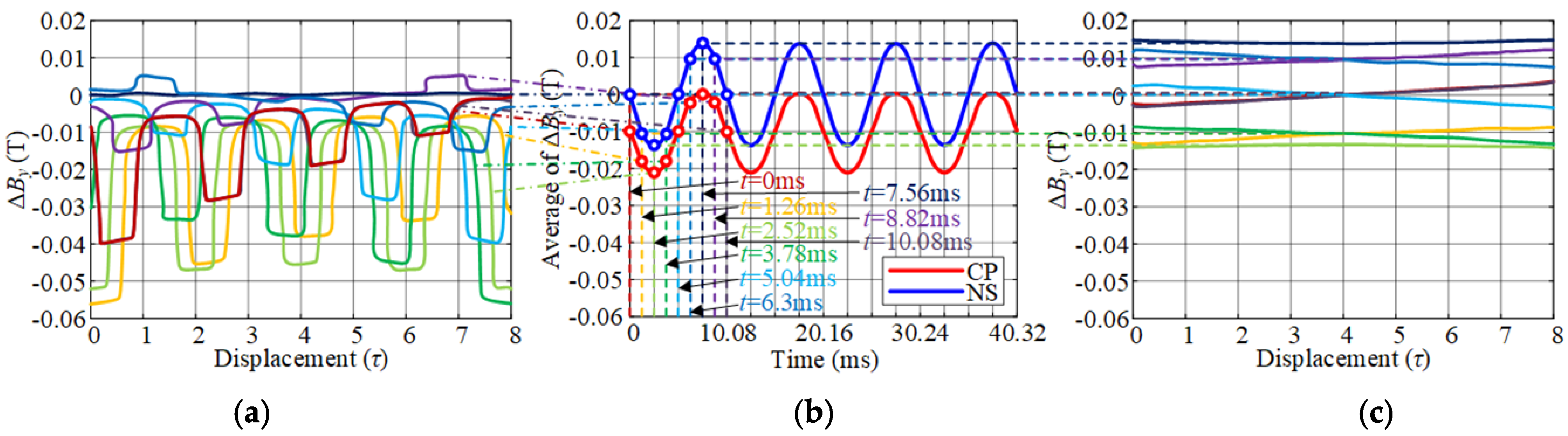
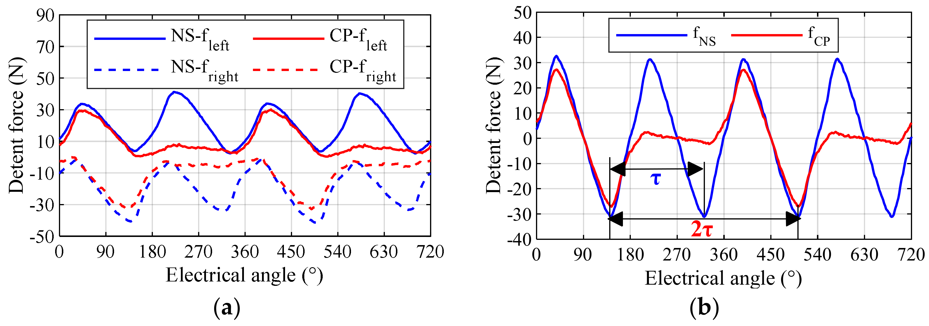
2.4. Modeling of CP-PMLSM’s End Force

As shown in Figure 4c,d, the FEM models of semi-infinite primary are established to obtain the single end force. The FEM modeling method of the NS-PMLSM is the same as that of the CP-PMLSM, which is not repeated here. Through the semi-infinite FEM model, the relative positions of the left/right ends and the secondary change by “①-②-③-④”. The left and right end forces can be obtained, as shown in Figure 11a. The fluctuation period of the single end force of the NS-PMLSM is τ, while that of the CP-PMLSM is 2τ. When the position changes from ① to ② (0~180°), the left and right ends are both in the PM area, the peak values of single end force of the CP-PMLSM are slightly smaller than that of NS-PMLSM. But the position from ② to ③ (180°~360°), both the left and right ends of the CP-PMLSM are in the IP area, the amplitudes of the single end force change very little because the Φm1 is very small. Figure 11b shows the end force of the entire PMLSMs. The end force of NS-PMLSM fluctuates with the period of τ, but that of the CP-PMLSM fluctuates with a period of 2τ, which is consistent with the fluctuation law of pulsating magnetic field shown in Figure 6 and magnetic flux ΦCP(x) in Figure 10.
According to the above period and asymmetry characteristic, the end force of the CP-PMLSM within one period can be divided into two categories, fCP1 and fCP2. They are symmetrical and alternately distributed on the displacement x. Based on this, the piecewise function model of the CP-PMLSM’s end force can be established. As shown in Figure 12, PMs corresponds to the first category of end force fCP1, IPs corresponds to the second category of end force fCP2. x0 is the initial relative position of the primary and secondary. Among the entire displacement x, the interval corresponding to fCP1 is (x0 + 2, x0 + (2j + 1)τ), the interval corresponding to fCP2 is (x0 + (2j + 1)τ, x0 + (2j + 2)τ), where j is an integer. The piecewise function model of the CP-PMLSM’s end force can be expressed as Equation (7).
f = f C P 1 = n = 1 F C P 1 n 2 cos n π τ L 1 cos 2 n π τ x + n π τ L 1 f C P 2 = n = 1 F C P 2 n 2 cos n π τ L 1 cos 2 n π τ x + n π τ L 1
where L1 is the primary iron length; FCP1n and FCP2n are the amplitudes of the n-th component of fCP1 and fCP2 respectively. The calculation methods are the same with those of the NS-PMLSM.

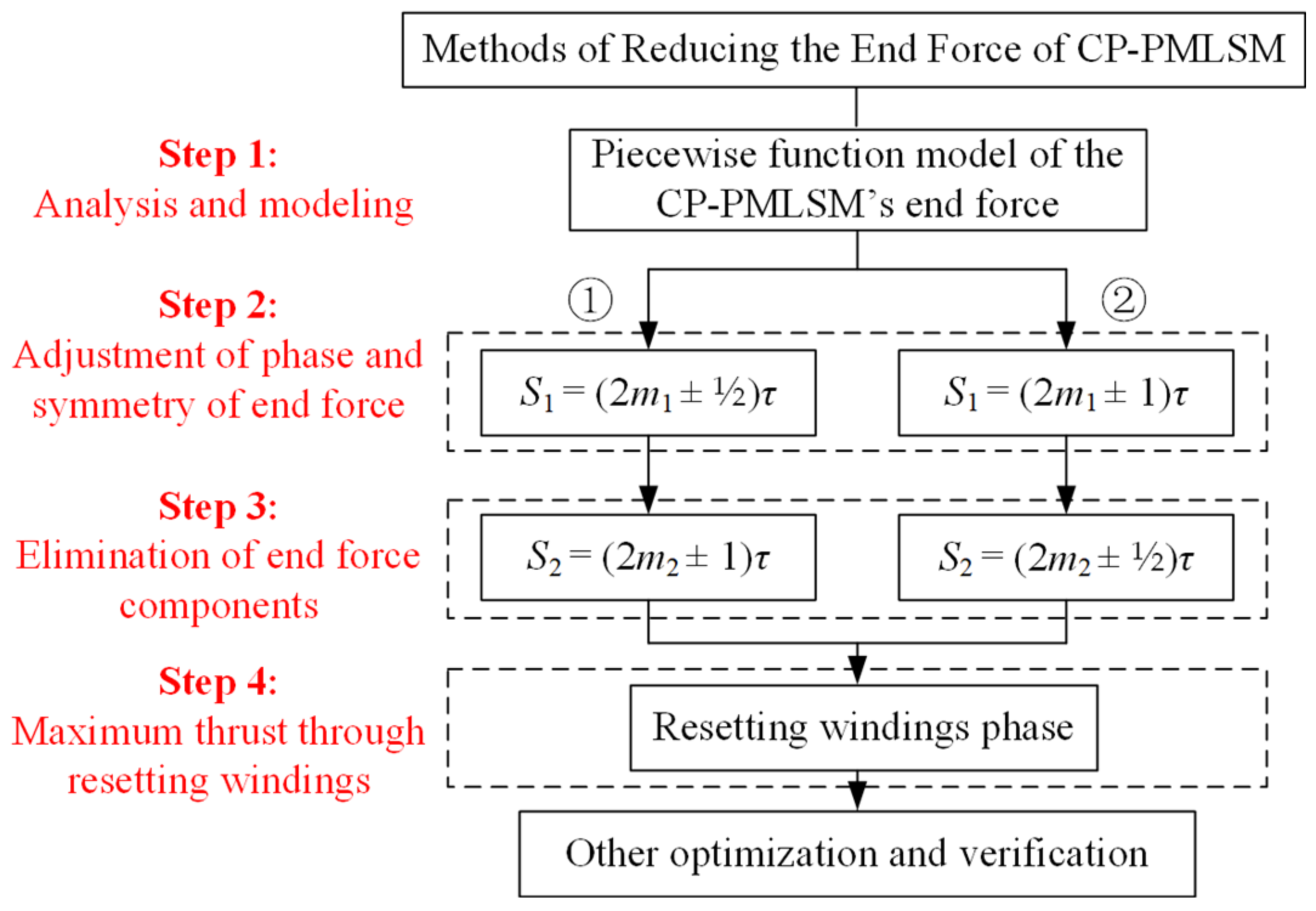
3. Two-Segment Design to Adjust the Period and Symmetry of the CP-PMLSM’s End Force

Modular design is a very effective method to reduce the end force of PMLSMs. In the existing modular design, the end force should be periodic symmetrical [22]. However, the end force of the CP-PMLSM is obviously asymmetry, so in this section, the two-segment method of adjusting the symmetry of the end force is discussed.

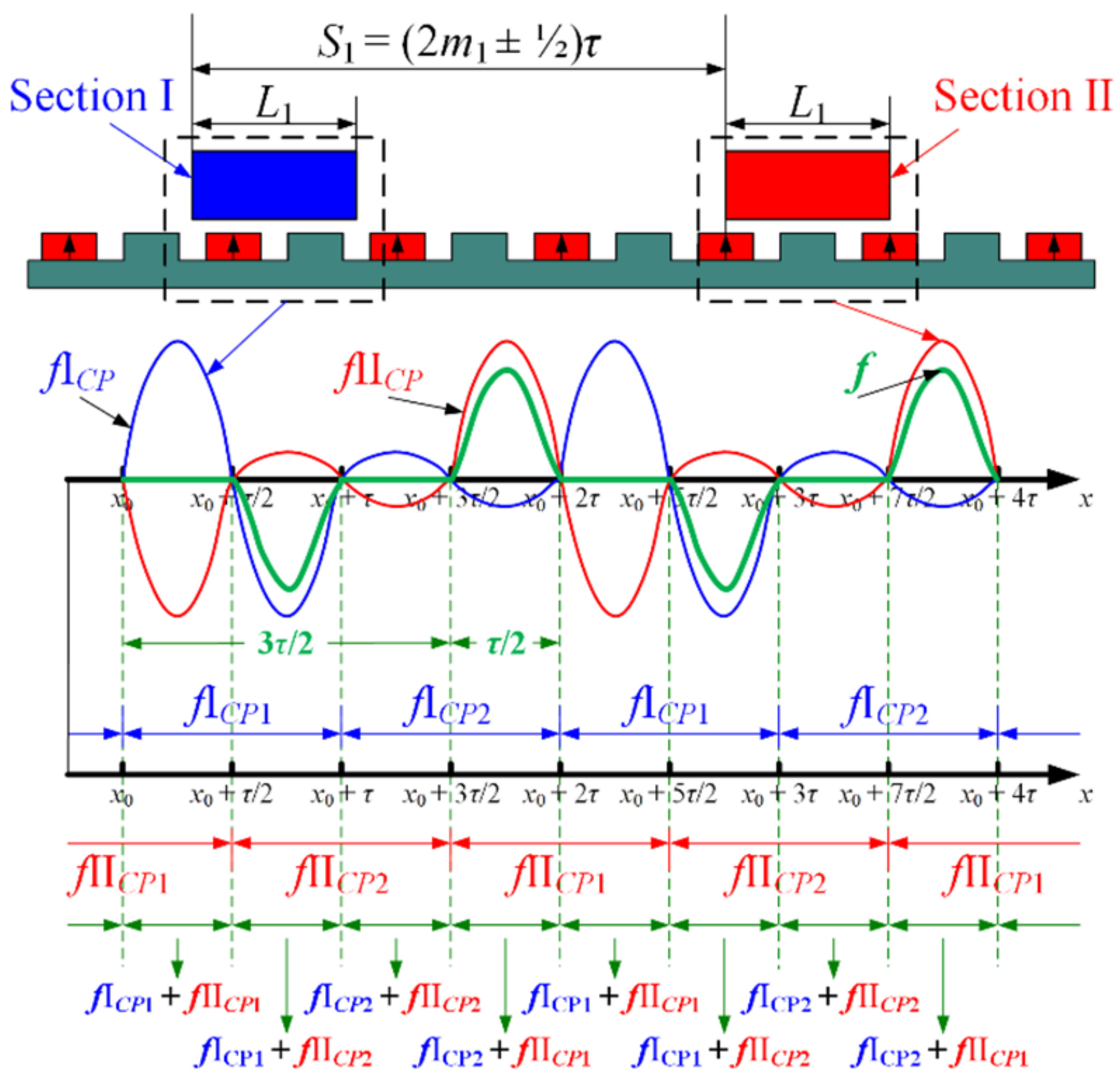
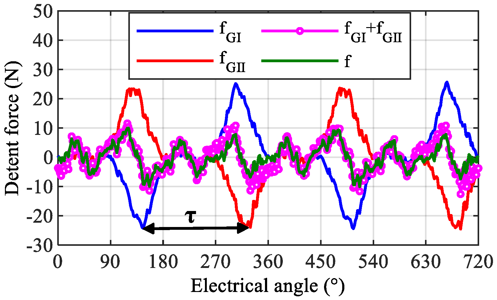
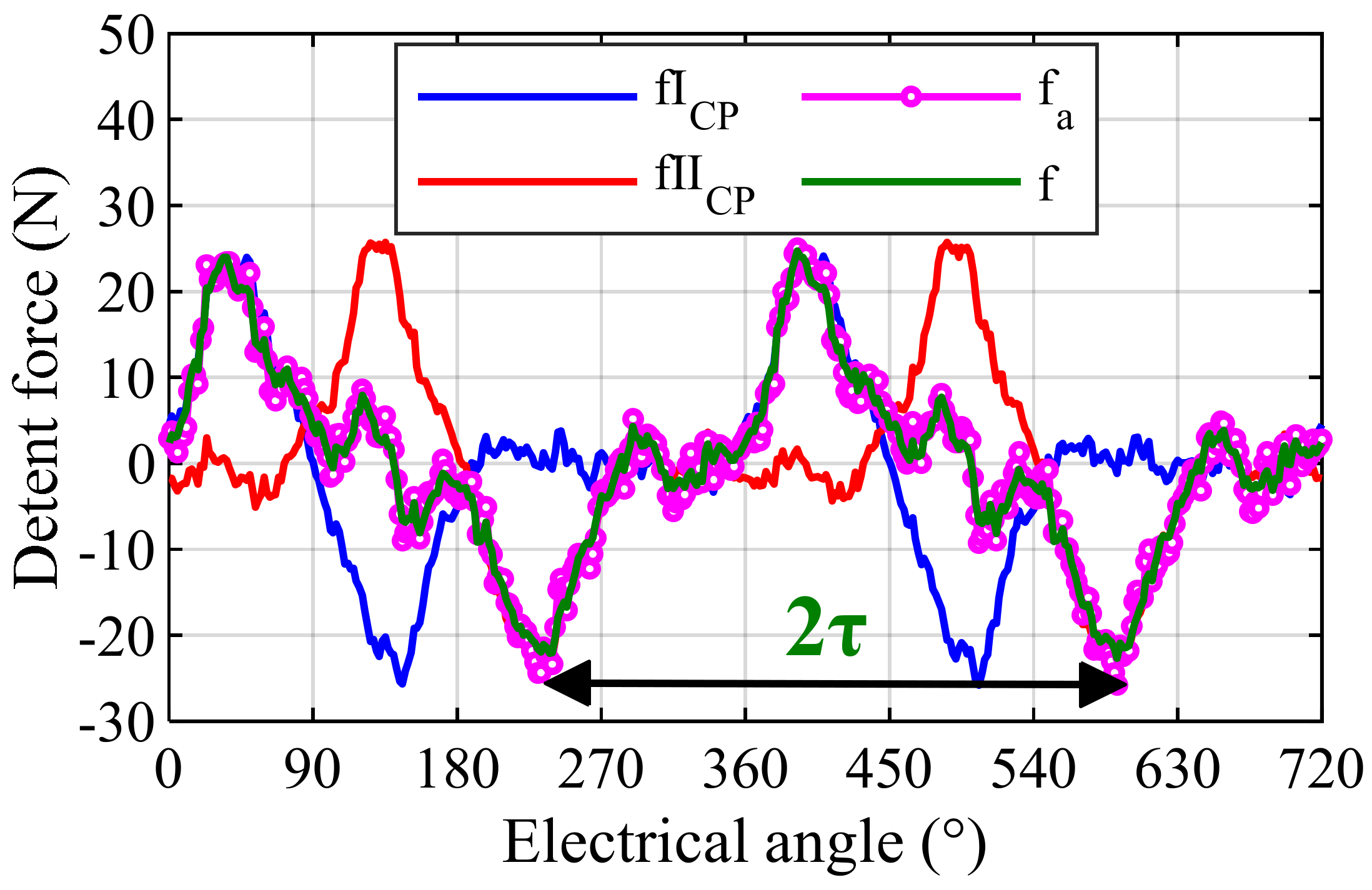
3.1. First Two-Segment Design to Adjust the Period to 2τ

Figure 13 shows a two-segment primary topology of the CP-PMLSM. The end forces of Section I and Section II are expressed as fICP and fIICP respectively. The distance between the left ends of the two sections is S1. It should meet the condition S1 = (2m1 + 1/2)τ (m1 is an integer). The addition of the two end forces of the two sections is f, which is a symmetrical waveform with a period of 2τ. It can be expressed as a piecewise Equation (8), which divides the displacement into four intervals in each period.
f = f I C P 1 + f II C P 1 , x x 0 + 2 j τ , x 0 + 2 j + 1 / 2 τ f I C P 1 + f II C P 2 , x x 0 + 2 j + 1 / 2 τ , x 0 + 2 j + 1 τ f I C P 2 + f II C P 2 , x x 0 + 2 j + 1 τ , x 0 + 2 j + 3 / 2 τ f I C P 2 + f II C P 1 , x x 0 + 2 j + 3 / 2 τ , x 0 + 2 j + 2 τ
Ideally, it can be considered that the waveforms of fCP1 and fCP2 on each interval are sinusoidal, that is, FICP1n = FIICP1n and FICP2n = FIICP2n. Therefore, Equation (8) can be further expressed as
f I C P 1 + f II C P 1 = f I C P 2 + f II C P 2 = 0 f I C P 1 + f I C P 2 = f I C P 2 + f II C P 1
The amplitude of each harmonic of the end force in the first and third intervals is 0, whereas the amplitude of that in the second and fourth intervals is |FCP1nFCP2n|.
Employing the parameters of the secondary of CP-PMLSM I listed in Table 1, and setting L1 = 2τ, S1 = 3.5τ, the end forces of Section I (fICP), Section II (fIICP), their superposition (fa = fICP + fIICP), and the whole motor (f) are drawn in Figure 14. The waveforms of f and fa are basically the same. At this time, f is a symmetrical waveform with a period of 2τ, and the fluctuation law basically conforms to Equation (9). Due to the different harmonic distribution of each end force on different modules in actual situations, the waveforms of (fICP1 + fIICP1) and (fICP2 + fIICP2) slightly fluctuate around 0 N.

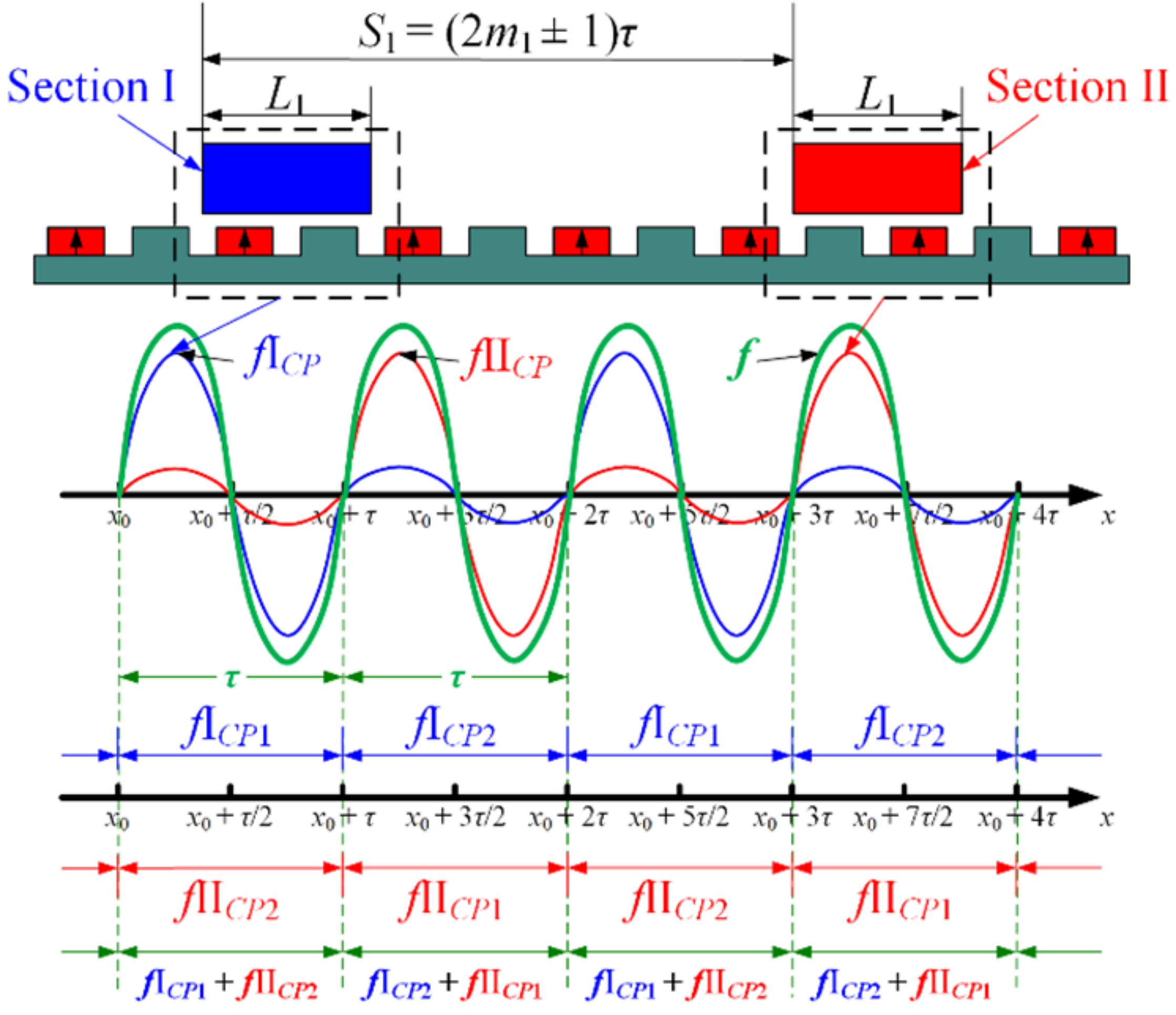
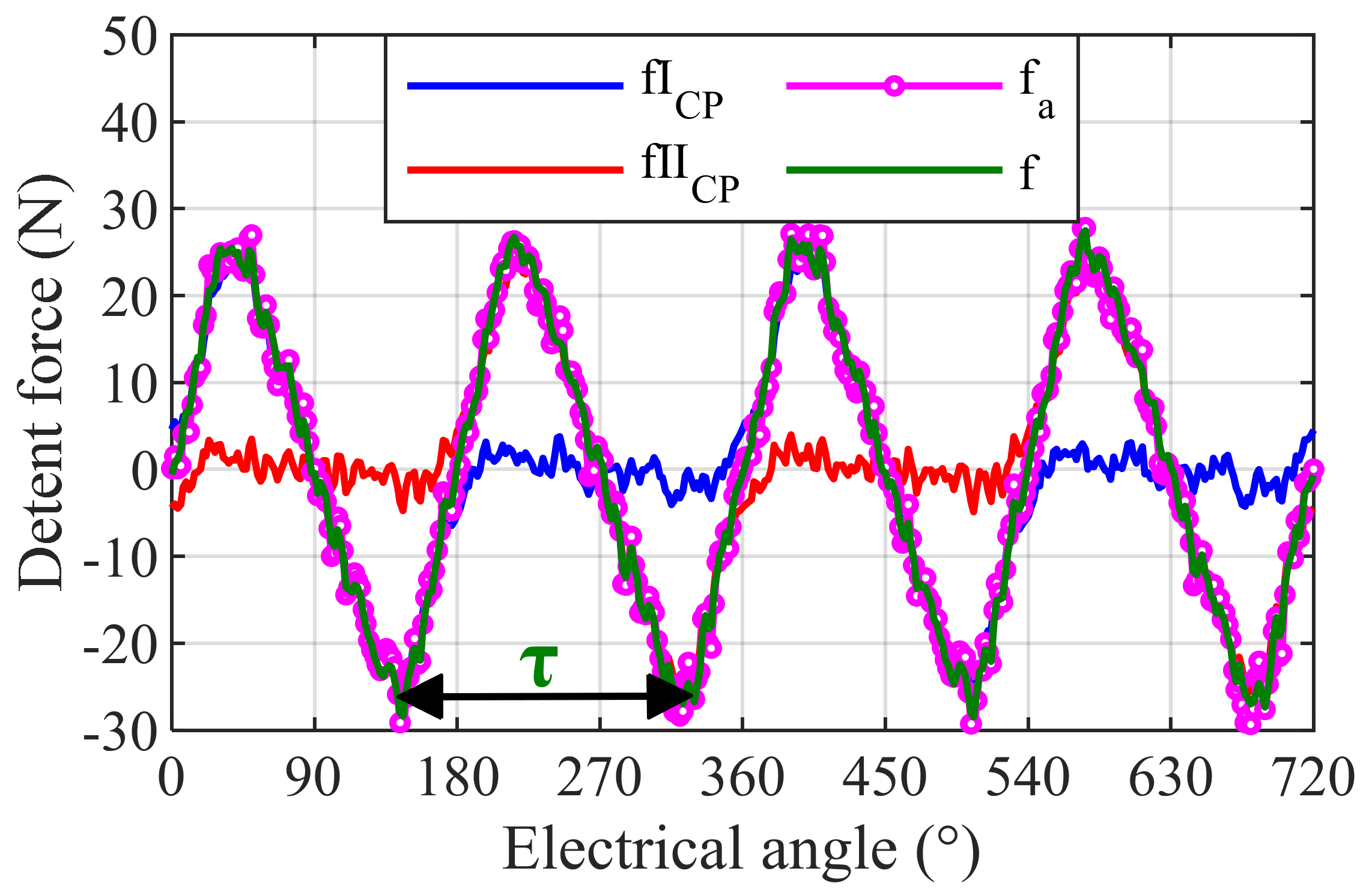
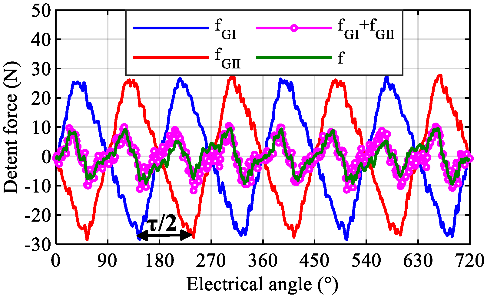
3.2. Second Two-Segment Design to Adjust the Period to τ

Figure 15 shows the second two-segment method. The modular distance satisfies S1 = (2m1 ± 1)τ, and the end force f is a symmetrical waveform with a period of τ, which can be expressed as a piecewise Equation (10). The displacement can be divided into two intervals in each cycle.
f = f I C P 1 + f II C P 2 , x x 0 + 2 j τ , x 0 + 2 j + 1 τ f I C P 2 + f II C P 1 , x x 0 + 2 j + 1 τ , x 0 + 2 j + 2 τ
Ideally, FICP1n = FIICP1n = FCP1n, FICP2n = FIICP2n = FCP2n, so Equation (10) can be expressed further as Equation (11).
f = n = 1 F C P 1 n + F C P 2 n 2 cos n π τ L 1 cos 2 n π τ x + n π τ L 1
The n-th harmonic amplitude is |FCP1n + FCP2n|. Figure 16 shows the curves of fICP, fIICP, fa = fICP + fIICP and f with the setting of L1 = 2τ, S1 = 3τ. The simulation results are basically consistent with (11).
In summary, through the first two-segment design, the end force waveform has achieved odd symmetry in the first half and the second half cycle. Moreover, the second two-segment method adjusts the period of the end force from 2τ to τ and realizes the symmetrical characteristics.

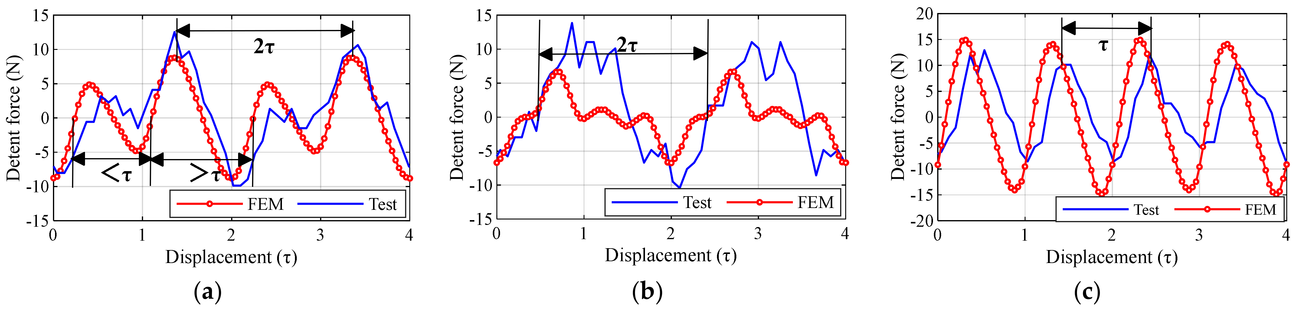
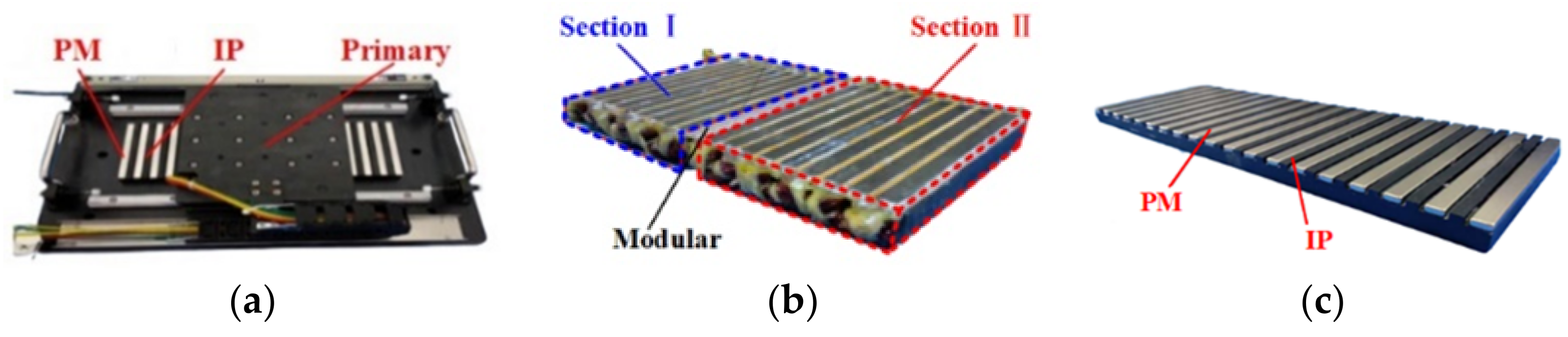
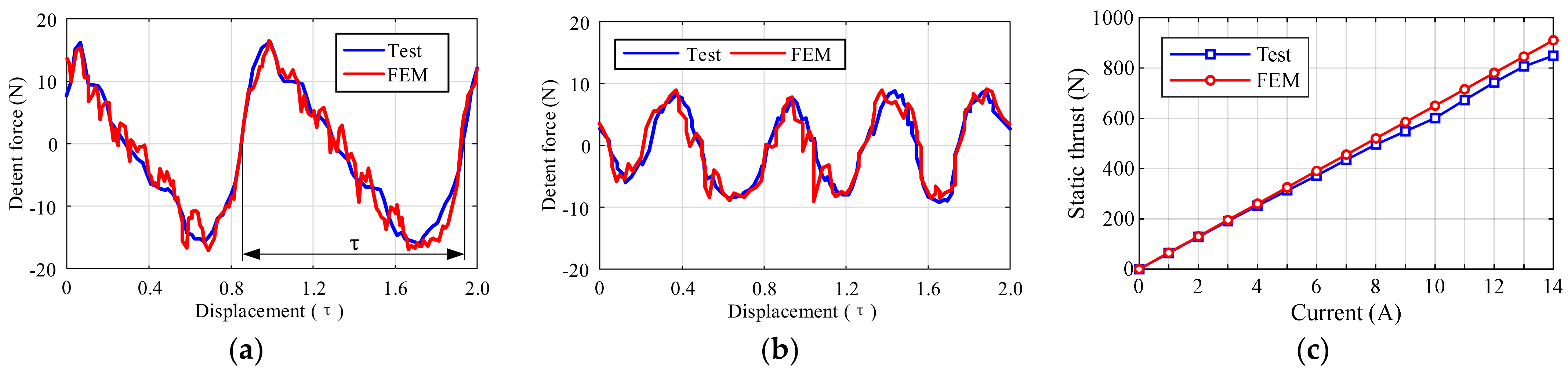
3.3. Experimental Verification

In order to obtain the same thrust as the NS-PMLSM, the developed test platform adopts the geometrical parameters of CP-PMLSM II listed in Table 1. The structure and parameters of the slotless iron are shown in Figure 17a. The single primary test platform is shown in Figure 17b. The two-segment primary test platform is shown in Figure 17c, in which the distance between the two primary segments can be adjusted. The primary iron, connectors, and tension pressure sensor are connected to the servo cylinder. The servo cylinder drives the primary to make a reciprocating linear motion. The tension pressure sensor feeds back the induced force to the oscilloscope to obtain the end force.
Figure 18 shows the experimental and simulated end force waveforms. For the single primary, the period of the end force is 2τ. Because the PM width is larger than the IP width in the test platform, as wPM > wIP, the sinusoidal period of the first type of end force is a little greater than 180°, and that of the second type of end force is a little less than 180°, which is different from the condition of wPM = wIP.
However, the principle of the two-segment design method is also applicable. In Figure 18b, the structure of S1 = (2m1 ± 1/2)τ adjusts the end force period to 2τ. Whereas the structure of S1 = (2m1 ± 1)τ adjusts the end force cycle to τ, as shown in Figure 18c. The periods of the experimental and simulated waveforms are exactly the same. There are some differences between the amplitudes of the tested and analyzed waveforms. The reasons may come from the machining and assembly errors of the air-gap, modular distance, and so on. Besides, the material inconsistency, sensor accuracy, and mesh generation in FEM calculation also have function on the difference.

4. Four-Segment Design to Eliminate Odd Harmonics of the CP-PMLSM’s End Force

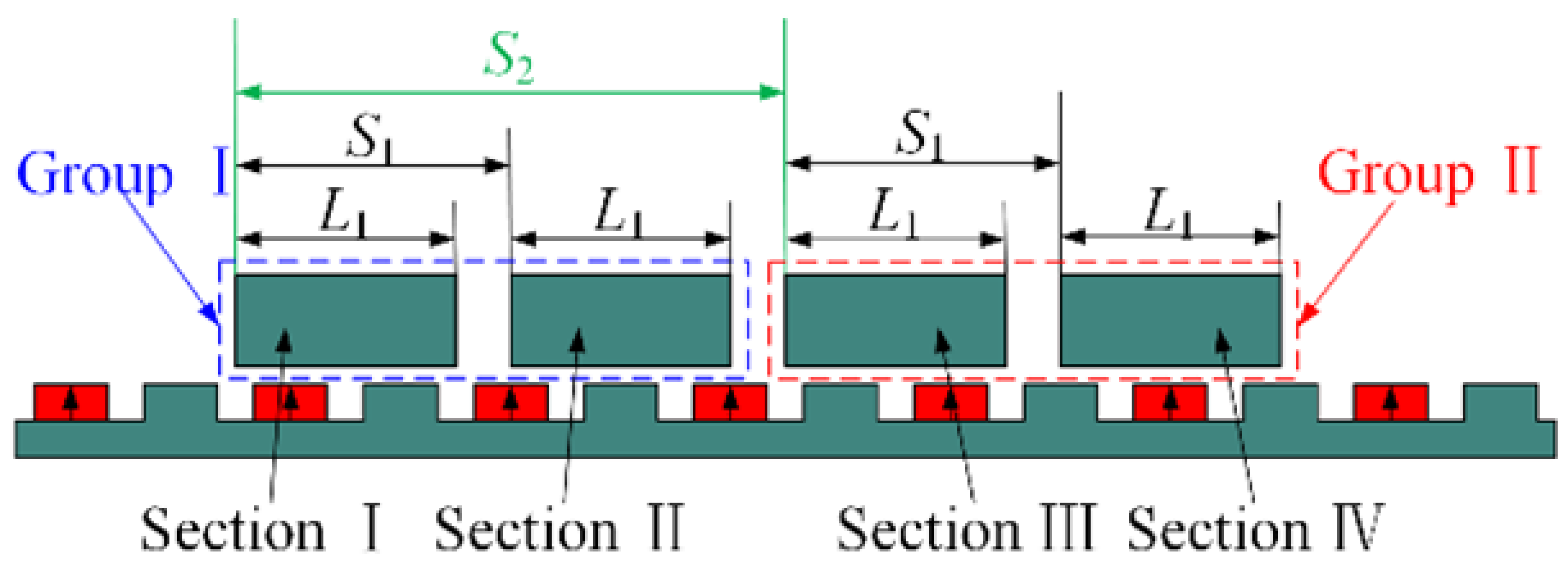
4.1. Four-Segment Structure and Spacing Matching

Figure 19 shows the grouped four-segment topology, including two groups. Each group includes two primaries, which are designed and located through the above two-segment design to obtain the periodic and symmetrical end force. The modular distance S2 is used to make the end forces of the two groups with the anti-phases, so that the fundamental and some harmonics can be eliminated. It should be noted that the value of S2 needs to match S1.
When S1 = (2m1 ± 1/2)τ, the end force of each group is symmetrically distributed with the period of 2τ. Then a phase difference of 180° exists between the end forces of the two groups, thus the end forces can be offset by each other. Under this circumstance, the value of S2 should be designed and matched as (2m2 ± 1)τ (m2 is an integer), forming the first type four-segment design method.
Figure 20 shows the end force of the first group, the second group, the sum of the two groups, corresponding to fGI, fGII and (fGI + fGII), respectively, as well as the end force of the entire motor (f). The amplitude of one single primary’s end force is 50.11 N. After employing the above modular design, the end force amplitude of the whole four-segment motor is reduced to 20.01 N. The Fourier decomposition results are shown in Table 2. The fundamental waveforms of the two groups differ with the phase angle 180°, which cancel each other out and are completely eliminated. Except for the fundamental component, the difference of the same odd harmonic components of the two groups’ end forces is also about 180°. Therefore, the odd-numbered harmonics can also be eliminated greatly. But the even-numbered harmonics have almost the same phase. Therefore, the remaining end force of the whole four-segment motor is mainly composed of even-numbered components.
Different from the above condition S1 = (2m1 ± 1/2)τ, when S1 = (2m1 ± 1)τ, the end force waveforms of each group are distributed symmetrically according to the period of τ. The phase difference of 90° is between the end forces of the two groups. In this case, the matching distance should be S2 = (2m2 ± 1/2)τ, forming the second type four-segment design method. Figure 21 shows the waveforms of fGI, fGII, (fGI + fGII) and f. The amplitude of the end force is reduced from 50.11 N for each primary to 19.15 N for the whole four-segment motor. The Fourier decomposition results are similar with the laws in Table 2, so the fundamental and odd harmonic components of the end forces can be eliminated.
In summary, the above two grouped four-segment design methods can effectively suppress the end force of CP-PMLSM. When the first method is employed, the minimum length of the entire four-segment motor’s primary is 4L1 + 1.5τ. Whereas when the second method is adopted, the minimum length is 4L1 + 2.5τ. In contrast, the first method is more conducive to reducing the length of the entire motor. Besides, it is recommended to set the cooling structure in the gap between the adjacent primaries, which can help reduce temperature rise, increase thrust density, and make full use of space.

4.2. Experimental Verification

In order to eliminate the influence of the slot effect, the slotless structures are used in the above studies and the exact characteristic of the end force of the CP-PMLSM is obtained. When the primary core adopts the slotted structure, the coupling of slot and end effects will generate. In order to investigate whether the group four-segment method is applicable for the CP-PMLSM with slotted structure, a slotted CP-PMLSM with 10-pole/9-slot combination is developed. As shown in Figure 22, the parameters of the secondary are wPMwIP. The output thrust is nearly kept the same as that of the NS-PMLSM, thus it is convenient to compare the other properties, such as the usage of PM, detent force. The second type of two-segment method is used to design the mover. The mover can be seen as one group in the four-segment design. The specific parameters of the prototype are listed in Table 3.
The group of primaries is driven to carry out linear motion from an initial position. The FEM simulation and experimental results are shown in Figure 23. The detent force of a single group in Figure 23a includes the cogging force coming from the slot effect and end force coming from the end effect. Because of the second two-segment design method, the period of the detent force is adjusted to τ. The simulation and experimental waveforms fit each other very well.
The detent force of group I is obtained based on the given initial position. The detent force of group II can be obtained by moving the group of primaries along the initial position by τ/2. Through superposing the measured detent forces of group I and group II, the detent force of the entire four-segment motor is shown in Figure 23b, which amounts to the second four-segment method. The results of the simulation and experiment are also consistent. Compared with the detent force of a single group, the detent force of the entire motor is also greatly reduced. It also verifies the universality and effectiveness of the primary segmented design method proposed in this paper on slotless and slotted structures.
Figure 23c shows the static thrust of the entire motor. The experimental and simulated values are basically the same. It should be noted that the primary segmented design method will cause the back EMF phase of the same phase windings on each section to change, so it is necessary to adjust winding phase sequence on each segment to maximize the back EMF and thrust of the entire motor [23].
In short, the end force and thrust fluctuation suppression of CP-PMLSM can be divided into three steps, as shown in Figure 24. The first step is establishing the piecewise function model of the end force of CP-PMLSM and analyzing the phase-amplitude characteristic. Then a two-segment design is used by designing the modular distance S1 to adjust the period and symmetry of the end force waveform. The third step is a grouped four-segment design. The modular distance S2 is designed to make the fundamental and odd components of the end forces be eliminated. The value of S2 is determined by the corresponding S1. Following this, the resetting of the windings to maximize the back EMF and thrust of the entire modular motor.

5. Conclusions

Compared with NS-PMLSM, CP-PMLSM has the advantage of saving the amount of PMs, and has a price superiority in long-secondary occasions. When outputting the same thrust, the PM dosage of CP-PMLSM is only about 80% of NS-PMLSMs. However, the magnetic circuits, pulsating magnetic fields and magnetic flux functions of CP-PMLSM and NS-PMLSM are different from each other. The curve of average values of pulsating magnetic field of the CP-PMLSM is in the half axis region which has a DC offset. The curve of square of average values of pulsating magnetic field of the CP-PMLSM fluctuates with 2τ. Therefore, the period and symmetry of end force generated by pulsating magnetic field are different between the CP-PMLSM and NS-PMLSM. The asymmetric end force of CP-PMLSM is divided into two categories for establishing the piecewise function model. The two-segment design methods can obtain periodic and symmetrical end forces through two types of modular distance S1. The grouped four-segment primary design methods can realize the anti-phase cancellation of the end forces with two kinds of combinations of modular distances S2 and S1. So far, the fundamental and odd harmonics of the end force are eliminated greatly. A slotless primary core test platform and a slotted CP-PMLSM prototype are developed to test the end force, detent force and static thrust, etc. The experimental results are almost consistent with the simulation results, verifying the correctness of the theoretical analysis and the generality of the above methods.

Author Contributions

Conceptualization, J.L. and X.H.; methodology, J.L. and X.H.; software, J.L.; validation, J.L., Y.L. and Z.W.; formal analysis, J.L.; investigation, J.L.; resources, X.H.; data curation, J.L.; writing—original draft preparation, J.L.; writing—review and editing, J.L., X.H. and B.Z.; visualization, J.L. and X.H.; supervision, X.H. and B.Z.; project administration, J.L. and X.H.; funding acquisition, X.H. All authors have read and agreed to the published version of the manuscript.

Funding

This research was funded by the National Natural Science Foundation of China, grant number 52022040.

Conflicts of Interest

The authors declare no conflict of interest.

References

  1. Petrov, I.; Pyrhonen, J. Performance of low-cost permanent magnet material in PM synchronous machines. IEEE Trans. Ind. Electron. 2013, 60, 2131–2138. [Google Scholar] [CrossRef]
  2. Li, J.; Wang, K.; Liu, C. Torque improvement and cost reduction of permanent magnet machines with a dovetailed consequent-pole rotor. IEEE Trans. Energy Convers. 2018, 33, 1628–1640. [Google Scholar] [CrossRef]
  3. Li, J.; Wang, K.; Liu, C. Comparative study of consequent-pole and hybrid-pole permanent magnet machines. IEEE Trans. Energy Convers. 2019, 34, 701–711. [Google Scholar] [CrossRef]
  4. Qu, H.; Zhu, Z.Q.; Li, H.Y. Analysis of novel consequent pole flux reversal permanent magnet machines. IEEE Trans. Ind. Appl. 2021, 57, 382–396. [Google Scholar] [CrossRef]
  5. Yang, K.; Zhao, F.; Wang, Y.; Bao, Z.C. Consequent-pole flux reversal permanent magnet Machine with halbach array magnets in rotor slot. IEEE Trans. Magn. 2021, 57, 8100905. [Google Scholar] [CrossRef]
  6. Yang, X.B.; Kou, B.Q.; Luo, J.; Zhang, H. A novel dual-consequent-pole transverse flux motor and its analytical modeling. IEEE Trans. Ind. Electron. 2021, 68, 4141–4152. [Google Scholar] [CrossRef]
  7. Chung, S.U.; Kim, J.W.; Chun, Y.D.; Woo, B.C.; Hong, D.K. Fractional slot concentrated winding PMSM with consequent pole rotor for a low-speed direct drive: Reduction of rare earth permanent magnet. IEEE Trans. Energy Convers. 2015, 30, 103–109. [Google Scholar] [CrossRef]
  8. Chung, S.U.; Moon, S.H.; Kim, D.J.; Kim, J.M. Development of a 20-pole–24-slot SPMSM with consequent pole rotor for in-wheel direct drive. IEEE Trans. Ind. Electron. 2016, 63, 302–309. [Google Scholar] [CrossRef]
  9. Li, F.; Wang, K.; Li, J.; Zhang, H.J. Suppression of even-order harmonics and torque ripple in outer rotor consequent-pole PM machine by multilayer winding. IEEE Trans. Magn. 2018, 54, 8108605. [Google Scholar] [CrossRef]
  10. Li, F.; Wang, K.; Sun, H.Y.; Kong, J.W. Influence of various magnetic pole on electromagnetic performance of consequent-pole permanent magnet machine. IEEE Access 2019, 7, 121853–121862. [Google Scholar] [CrossRef]
  11. Li, F.; Wang, K.; Li, J.; Sun, H.Y.; Luk, P.C.K. Electromagnetic performance analysis of PMSM with eccentric consequent pole rotor. In Proceedings of the 2017 7th International Conference on Power Electronics Systems and Applications—Smart Mobility, Power Transfer & Security (PESA), Hong Kong, China, 12–14 December 2017; Institute of Electrical and Electronics Engineers: New York, NY, USA, 1963. [Google Scholar] [CrossRef]
  12. Li, J.; Wang, K.; Li, F.; Zhu, S.S.; Liu, C. Elimination of even-order harmonics and unipolar leakage flux in consequent-pole PM machines by employing N-S-iron–S-N-iron rotor. IEEE Trans. Ind. Electron. 2019, 66, 1736–1747. [Google Scholar] [CrossRef]
  13. Li, J.; Wang, K. Analytical determination of optimal PM-arc ratio of consequent-pole permanent magnet machines. IEEE/ASME Trans. Mechatron. 2018, 23, 2168–2177. [Google Scholar] [CrossRef]
  14. Xu, X.Z.; Sun, Z.; Du, B.Y.; Ai, L.W. Pole optimization and thrust ripple suppression of new halbach consequent-pole PMLSM for ropeless elevator propulsion. IEEE Access 2020, 8, 62042–62052. [Google Scholar] [CrossRef]
  15. Botha, C.D.; Kamper, M.J.; Wang, R.J.; Chama, A. Analytical modeling of surface-mounted and consequent-pole linear vernier hybrid machines. IEEE Access 2021, 9, 26251–26259. [Google Scholar] [CrossRef]
  16. Luo, J.; Kou, B.Q.; Yang, X.B.; Zhang, H.; Zhang, L. Development, design, and analysis of a dual-consequent-pole transverse flux linear machine for direct-drive applications. IEEE Trans. Ind. Electron. 2021, 68, 6097–6108. [Google Scholar] [CrossRef]
  17. Chung, S.U.; Lee, H.J.; Woo, B.C.; Kim, J.W.; Lee, J.Y.; Moon, S.R.; Hwang, S.M. A feasibility study on a new doubly salient permanent magnet linear synchronous machine. IEEE Trans. Magn. 2010, 46, 1572–1575. [Google Scholar] [CrossRef]
  18. Chung, S.U.; Kim, J.M.; Woo, B.C.; Hong, D.K.; Lee, J.Y. Development of doubly salient permanent magnet linear synchronous motor for general-purpose automation applications. Int. J. Precis. Eng. Manuf. 2013, 14, 2075–2080. [Google Scholar] [CrossRef]
  19. Chung, S.U.; Kim, J.W.; Woo, B.C.; Hong, D.K.; Lee, J.Y.; Chun, Y.D.; Koo, D.H. Design and experimental validation of doubly salient permanent magnet linear synchronous motor for precision position control. Mechatronics 2013, 23, 172–181. [Google Scholar] [CrossRef]
  20. Chung, S.U.; Kim, J.W.; Woo, B.C.; Hong, D.K.; Lee, J.Y.; Koo, D.H. Force ripple and magnetic unbalance reduction design for doubly salient permanent magnet linear synchronous motor. IEEE Trans. Magn. 2011, 47, 4207–4210. [Google Scholar] [CrossRef]
  21. Tan, Q.; Wang, M.Y.; Li, L.Y.; Li, J.C. Pulsating magnetic field of permanent magnet linear synchronous motor and its influence on detent force. IEEE Trans. Energy Convers. 2021, 36, 703–712. [Google Scholar] [CrossRef]
  22. Huang, X.Z.; Yu, H.C.; Zhou, B.; Li, L.Y.; Gerada, D.; Gerada, C.; Qian, Z.Y. Detent-force minimization of double-sided permanent magnet linear synchronous motor by shifting one of the primary components. IEEE Trans. Ind. Electron. 2020, 67, 180–191. [Google Scholar] [CrossRef]
  23. Li, J.; Huang, X.Z.; Zhou, B.; Yu, H.C.; Huang, Q. Design principle of a 16-pole 18-slot two sectional modular permanent magnet linear synchronous motor with optimisation of its end tooth. IET Electr. Power Appl. 2020, 14, 441–447. [Google Scholar] [CrossRef]
Figure 1. Motor structure with slotless primary: (a) NS-PMLSM; (b) CP-PMLSM.
Symmetry 13 02374 g001
Figure 2. Simplified magnetic circuits: (a) NS-PMLSM; (b) CP-PMLSM.
Symmetry 13 02374 g002
Figure 3. Ratio of thrust to PM volume: (a) NS-PMLSM I; (b) CP-PMLSM I.
Symmetry 13 02374 g003
Figure 4. FEM models: (a) Master-slave boundary; (b) Whole motor with vector magnetic potential boundary; (c) Semi-infinite right end; (d) Semi-infinite left end.
Symmetry 13 02374 g004
Figure 5. Air-gap flux density and pulsating magnetic field: (a) CP-PMLSM; (b) NS-PMLSM.
Symmetry 13 02374 g005
Figure 6. Pulsating magnetic field. (a) Curves of the pulsating magnetic field at different time of CP-PMLSM; (b) Average values of the pulsating magnetic field varying with time; (c) Curves of the pulsating magnetic field at different time of NS-PMLSM.
Symmetry 13 02374 g006
Figure 7. Square of average values of ΔBy.
Symmetry 13 02374 g007
Figure 8. Schematic of magnetic flux function through the primary end of NS-PMLSM: (a) Maximum end flux Φm (x = 0); (b) End flux decreases gradually; (c) End flux is zero (x = τ/2); (d) End flux increases gradually; (e) Maximum end flux Φm (x = τ); (f) End flux decreases gradually; (g) End flux is zero (x = 3τ/2); (h) End flux increases gradually.
Symmetry 13 02374 g008
Figure 9. Schematic of magnetic flux function through the primary end of CP-PMLSM: (a) Maximum end flux Φm1 (x = 0); (b) End flux is zero (x = p1); (c) End flux increases gradually; (d) End flux increases gradually; (e) Maximum end flux Φm2 (x = τ); (f) End flux decreases gradually; (g) End flux is zero (x = 2τp1); (h) End flux increases gradually.
Symmetry 13 02374 g009
Figure 10. Approximate relationship between Φ(x) and x.
Symmetry 13 02374 g010
Figure 11. Curves of end force: (a) Single-end end force; (b) End force.
Symmetry 13 02374 g011
Figure 12. Two categories of CP-PMLSM’s end force.
Symmetry 13 02374 g012
Figure 13. Principle of the first two-segment topology adjusting the end force period to 2τ.
Symmetry 13 02374 g013
Figure 14. Detent force when “L1 = 2τ, S1 = 3.5τ”.
Symmetry 13 02374 g014
Figure 15. Principle of the second two-segment topology adjusting the end force period to τ.
Symmetry 13 02374 g015
Figure 16. Detent force when “L1 = 2τ, S1 = 3τ”.
Symmetry 13 02374 g016
Figure 17. Test platform: (a) Single primary section with slotless iron; (b) Single primary test platform; (c) Two-segment primary test platform.
Symmetry 13 02374 g017
Figure 18. Experimental and simulation waveforms: (a) Detent force of single section; (b) S1 = (2m1 ± 1/2)τ; (c) S1 = (2m1 ± 1)τ.
Symmetry 13 02374 g018
Figure 19. Grouped four-segment topology.
Symmetry 13 02374 g019
Figure 20. Detent force when “L1 = 2τ, S1 = 3.5τ, S2 = 7τ”.
Symmetry 13 02374 g020
Figure 21. Detent force when “L1 = 2τ, S1 = 3τ, S2 = 5.5τ”.
Symmetry 13 02374 g021
Figure 22. Prototype test platform: (a) Slotted CP-PMLSM prototype; (b) A group of primary; (c) CP secondary.
Symmetry 13 02374 g022
Figure 23. Experimental and simulation waveforms: (a) Detent force of single group; (b) Detent force of whole motor; (c) Static thrust variation with current.
Symmetry 13 02374 g023
Figure 24. Flow chart of primary segment design method.
Symmetry 13 02374 g024
Table 1. Parameters of PMLSMs (unit: mm).
SymbolQuantityNS-PMLSM ICP-PMLSM ICP-PMLSM II
wPM = wIPwPMwIP
τpole pitch10.0810.088.1
wPMPM width6.96.98
hPMPM height2.52.55
wIPIP width/6.95
hIPIP height/2.55
L1primary length100.8100.881
PM%PM dosage100%50%80%
Table 2. Harmonic distribution.
Harmonic OrderGroup IGroup II
Amplitude (N)Phase (°)Amplitude (N)Phase (°)
DC0.022270.00.064270.0
112.090135.012.570−44.9
21.962267.31.935268.1
37.084224.36.97845.6
42.514−2.52.469−2.8
52.308−48.42.308136.1
Table 3. Parameters of slotted CP-PMLSM (Unit: mm).
SymbolQuantityValueSymbolQuantityValue
gair gap0.5τpole pitch8.1
t1slot pitch9.0wPMPM width8.0
wsslot width4.6hPMPM height3.8
wttooth width4.4wIPIP width5.0
httooth height11.4hIPIP height3.8
he1primary yoke height3.0he2secondary yoke height10.7
Publisher’s Note: MDPI stays neutral with regard to jurisdictional claims in published maps and institutional affiliations.

