Abstract
Visual cryptography (VC) has found numerous applications in privacy protection, online transaction security, and voting security, etc. To counteract potential cheating attacks, Lin et al. proposed flip visual cryptography in 2010, where a second secret image can be revealed by stacking one share with a flipped version of another share. The second secret image can be designed as an additional verification mechanism. However, Lin’s scheme produces meaningless shares and is only applicable to binary secret images. It is interesting to explore whether it is possible to extend the flip VC to having cover images (i.e., extended VC) and these cover images are color images. This problem is challenging since too many restricting conditions need to be met. In this paper, we designed a flip VC for gray-scale and color cover images based on constraint error diffusion. We show that it is possible to meet all the constraints simultaneously. Compared with existing schemes, our scheme enjoys the following features: Color cover images, no computation needed for decoding, and no interference from cover image on the recovered secret image.
1. Introduction
In today’s world, information is a popular application resource and an essential carrier of communication in our lives. The rapid development of science and technology has driven the continuous advancement of information technology, and more people have begun to pay attention to the importance of information. At the same time, more and more people have put forward more security requirements for the protection of their privacy [,,]. Visual cryptography (VC) is an important branch of information security and has been further developed in the field of secret sharing. It can not only ensure the security of people’s privacy but also has a simple decoding operation and numerous potential applications. Therefore, visual cryptography technology has become a hot research direction since its proposal in 1994.
Naor and Shamir designed the first visual cryptography algorithm in 1994 []. The basic idea is to replace each pixel in an image with a block of pixels. The pixel information in the pixel block is filled with the superposition between pixels, and finally, an encrypted image cannot be recognized by the human eye [,,,,,,,,,]. For a -threshold scheme, The information transmitting end encrypts the secret image into k share images and transmits them to the receiving end. After receiving the k share images, The receiving end superimposes and restores the secret image. The recovered secret image is displayed in black and white by the synthesized pixels. If the receiving end receives less than k share images, The secret image cannot be recovered. Therefore, The visual cryptography scheme has sufficient security and feasibility. However, if a secret image is encrypted by this scheme, The pixels are expanded to m pixels, in order to generate k noise-like share images. The size of the recovered secret image is m times of the size of the original image. Each of the black pixels and the white pixels is composed of a certain number of sub-pixels, i.e., a mixture of black and white. So, The visual quality of the recovered secret image is not ideal. Therefore, more visual cryptography algorithms tried to improve the image quality of the stacked image [,].
There is a trade-off between the quality of the recovered secret image and the size expansion. Ordinary visual cryptography divides the secret image pixels into blocks and embeds the secret pixel information with the basic matrix. Since each secret pixel can be rendered by a block of pixels in a recovered image, ordinary visual cryptography has better visual quality. However, The recovered secret image is larger than the original secret image []. In 2002, Nakajima and Yamaguchi proposed extended visual cryptography for natural images []. This scheme can produce a meaningful share of images. The use of halftone technology and contrast-enhancing methods improves the quality of recovering secret images. In 2011, Liu and Wu proposed a scheme that combined extended VC with digital halftoning. Embedding a cover image into a share image improves the quality of the share image [].
The development of meaningful visual cryptography provides more room for the development of subsequent visual cryptography technologies because, with meaningful VC, share images can be stored in large quantities, which is convenient for encrypting more secret information. Naor and Shamir also designed the first meaningful VC [], which has a good visual quality and is easier to store multiple share images. At the same time, share images are less likely to attract the attention of attackers. Image encryption often uses halftone images and gray-scale images, so meaningful visual cryptography requires high fidelity for share images. There are mainly two types of meaningful visual cryptography algorithms: the first is to process in the frequency domain, and then use the original encryption algorithm to embed the encrypted secret image in the frequency domain of the cover image by wavelet transform, and finally output a gray band share images with covered images []. For the second method, The gray-scale image is halftoned in the spatial domain, and then the cover image is embedded in the share image using the pixel compensation method [].
Color visual cryptography is also one of the main researches in the field of visual cryptography [,]. Color visual cryptography has good visual quality. The earliest research on color visual cryptography was the color visual cryptography (k, n) solution. The secret image is encrypted into n share images, and no less than k share images are taken to superimpose to obtain the secret image. In 2000, Yang and Laih constructed a new color visual cryptography scheme. The basic structure of the sub-pixels can be directly used for the proposed structure in the image editing package, and it is easy to implement []. In 2003, Hou proposed VC algorithms for color images. He proposed three VC methods for VC and grayscale images. These methods are based on VC for binary images, digital halftoning, and color decomposition methods. These methods have similar VC advantages to binary images []. In 2011, Prakash and Govindaraju proposed a color visual cryptography scheme based on direct binary search (DBS) with adaptive searching and exchange functions []. Through this solution, a better halftone image can be generated, in addition to lossless recovery.
We conclude the literature review by noting that, even though a color extended VC with authentication capacity is desired, currently no such design is reported. One possible reason is that to design such a VC system, one needs to meet many restrictions.
In this paper, a meaningful flipping visual cryptography algorithm is proposed based on the constraint error diffusion. The main features of our system are as follows:
- The cover image can be a gray-scale image or color image. So, The share image is meaningful.
- The share image and the cover image are of the same size, and there is no pixel expansion after encryption.
- Two secret images are simultaneously embedded. That is, by superimposing two share images on the front side, one obtain a secret image ; by superimposing the share image and the flipped share image , one obtain the second secret image .
- When the secret image are recovered by stacking, there is no interference from the cover image.
To the best of our knowledge, currently, there is no VC algorithm that meets all the above requirements.
The structure of this paper is as follows: Related background is reviewed in Section 2. In Section 3, we present a meaningful flipping visual cryptography algorithm. Section 4 combines the color VC algorithm to obtain color meaningful flip VC. Section 5 provides the experimental results. Section 6 concludes this paper.
2. Related Works
This paper is divided into two parts: gray-scale meaningful flipping visual cryptography and color meaningful visual cryptography. Meaningful flipping visual cryptography uses the method of constrained error diffusion to embed the cover image into the share images, which improves the visual quality of the share images and can better protect the secret image from being discovered. Color flip visual cryptography can encrypt color secret images, and the share images are color images with better visual quality. In this section, we review the basic structure of VC with meaningful shares and flip VC [,]. Unless otherwise stated, all the secret images in this section and next section are binary images.
We would like to ask our readers to pay attention to the difference between the secret image and the share images.
- A binary secret image is a digital image stored in a computer disk and/or memory, and it consists of white pixels and black pixels. Following the convention in VC and digital halftoning, we use a ‘1’ to represent a black pixel on the secret image, and we use a ‘0’ to represent a white pixel on the secret image.
- A share image is printed on a transparency. When printing on paper, which is white by default, a printer only needs to print a black dot or print ‘no dot’. Most printers are not able to print white color except for some UV printers that are designed to print on cloth and plastic. So, when printing a share image on a transparency, a black pixel is printed as black while a white pixel is printed as ‘transparent’ since no dot is printed. So, when referring to a ‘white’ pixel on a transparency, we use the term ‘transparent’ pixel. Following the convention in VC and digital halftoning, we use a ‘1’ to represent a black pixel on a transparency, and we use a ‘0’ to represent a transparent pixel on a transparency.
2.1. VC with Meaningful Shares
A VC system with meaningful shares is also referred to as the extended VC in the literature. The overall structure of such a system is illustrated in Figure 1. For illustration purposes, we consider the case with two secret images and two cover images. A secret image is an image that the holder would like to share and would like to keep confidential during the sharing process. It can be a binary image, grayscale image, or even color image. In Figure 1, and are two secret images. In an ordinary VC, these secret images are encoded into share images and that are noise-like (i.e., meaningless). These share images are printed on transparencies, such as projector films or other transparent plastic thin sheets. Then the share images are distributed to different parties (also called participants). However, these noise-like shares may arouse the suspicion of an attacker. Extended VC is a countermeasure to this issue, where natural-looking cover images are used to generate shares. The two images and are two cover images. After gathering enough shares, a VC decoder can decode the secret images by simply stacking the transparencies carrying the shares. By inspecting the stacking results, a human is able to read the secret using his/her human vision system. So a VC decoder, in its strict sense, doesn’t need computation. In Figure 1, and are two decoded secret images. These images are also referred to as target images in the VC literature. The target image is usually not the same as its secret image counterpart. However, as long as the content of the secret image can be recognized from the target image, one deems the decoding as valid.
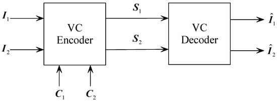
Figure 1.
Structure of a VC system with meaningful shares.
The most basic and simple algorithm model of visual cryptography is the (2, 2) scheme proposed by Naor and Shamir, which can be considered as a degenerated version of extended VC. It is also a building block of extended VC, so we review it briefly with a focus on its encoder. In the (2, 2)-threshold scheme, The secret image is encrypted into two share images. Even if an attacker obtains one of the share images, The secret image cannot be inferred from it. Two share images are needed in order to recover the secret image. The (k, n) threshold VC is an extension of (2,2) threshold scheme, that is, The secret image is encrypted to generate n share images. Only when k or more share images are superimposed, The secret image can be restored. A -threshold scheme consists of two collections of matrices, such as:
It should be noted that all the matrices in a set , where , can be obtained by column permutation of a basic matrix. For example, all matrices in can be obtained by column permutation of the matrix
Similarly, all matrices in can be obtained by column permutation of the matrix
So and are usually called the basic matrices for this -threshold VC scheme [].
To encode a white pixel, one randomly chooses a matrix from the set and assign the first row to share 1 and the second row to share 2. Likewise, when encoding a black pixel, one randomly chooses a matrix from the set and assign the first row to share 1 and the second row to share 2.
To illustrate this encoding process, let us consider a toy example as shown in Figure 2. The secret image consists of two pixels on a white paper, a black pixel (top) and a white pixel (bottom). To encode the black pixel, we randomly choose a matrix from the set . Suppose that the matrix
is chosen. Then the first row of , which is , is assigned to share 1 and the second row of , which is , is assigned to share 2. Noting that the shares are printed on transparencies, so share 1 gets a black pixel and a transparent pixel on its transparency, and share 2 get a transparent pixel and a black pixel on its transparency. When stacking share 1 and share 2, The stacking result consists of two black pixels. Likewise, to encode the second secret pixel (i.e., a white one), we randomly choose a matrix from the set . Suppose that we get the matrix
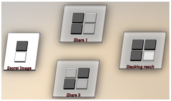
Figure 2.
A 3D illustration of basic -threshold VC. Please note that share 1 and share 2 are printed on transparencies.
Then the first row of is is assigned to share 1 and the second row of is is assigned to share 2. So, share 1 gets a black pixel and a transparent pixel on its transparency, and share 2 gets the same pattern as share 1. When stacking share 1 and share 2, The stacking result consists of one black pixel and one transparent pixel. So, after stacking, it is possible to distinguish between the white pixel and the black pixel in the secret image.
2.2. Flip VC
In 2010, Lin et al. proposed a flipping visual cryptography scheme based on non-expanded VC []. The general structure of a flip VC is shown in Figure 3. Two secret images, and , are encoded to generate two shares and . At the decoder side, if and are stacked, an image is generated, which reveals the content of the secret image . However, if we flip horizontally before stacking with (A flipping operation on an image is a horizontal mirroring operation so that two pixels at positions and are exchanged, where N is the number of columns of that image, and i is row index. For a more precise definition, please refer to Section 3.1), then a different image can be generated, which reveals the contents of . So, a flip VC can encode two different secret images into two shares simultaneously.
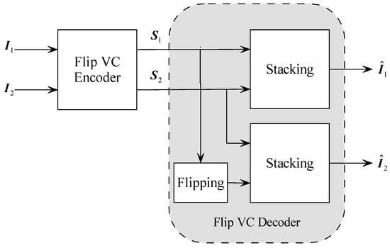
Figure 3.
The block diagram of flip visual cryptography (VC).
However, more restrictions are enforced on encoder in flip VC than ordinary VC. Figure 4 shows the stacking operation by the decoder. While in conventional VC one only needs to consider one pixel a time, now we need to consider operations on four pixels simultaneously, where is the pixel at the location of share image , and N is the number of columns. These four pixels can be grouped into a quadruple
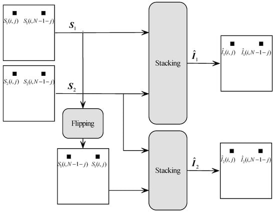
Figure 4.
Restrictions imposed on shares by flip VC decoder.
To recover the secret image, The decoder must meet the following requirements:
- Stacking with , the secret image should be revealed, i.e., , where ⊗ denotes the stacking operation.
- Stacking with , the secret image should be revealed, i.e., .
- Stacking with , the secret image should be revealed, i.e., .
- Stacking with , the secret image should be revealed, i.e., .
The first two conditions ensure that when and are stacked, we can decode the secret image . The last two conditions ensure that when flipped is stacked with , we can decode the secret image .
Lin et al. constructed 16 basic matrices for each of the quadruples
where B denotes ‘black’ and W denotes ‘white’. As an example, The basic matrix for quadruple ‘BWBB’ is []:
So, if the encoder needs to encode the quadruple
then it randomly selects one column from the basic matrix and assign it to the four pixels on the two shares and , respectively. It is not difficult to verify that, when the first row and the third row of are stacked, The ratio of black is 1. This ensures that when stacking and , The probability of black pixel is 1. When the second row and the fourth row are stacked, The ratio of black is 5/6. This ensures that when stacking and , The probability of black pixel is 5/6 and the probability of white pixel is 1/6. So a relative contrast of can be ensured on stacking results. For a complete list of the 16 basic matrices, please refer to Table 1 in []. Lin also proved that using these basic matrices, a relative contrast of can be ensured on stacking results. Furthermore, his construction is also proved to be secure.
3. Proposed Scheme
Before elaborating on the proposed algorithm, let us fix the notations for matrix operation and share stacking.
3.1. Definition of Operation
Definition 1 (matrix concatenation).
Let be one of the matrices in the share matrix, where are the position indices of the block matrix in the share matrices. Define
as the concatenation of matrices. For example, if
then we have
Definition 2 (stacking).
Operation for image stacking ⊗ is the logical OR operate, where. For two matrices and , results in pixel-wise OR between two pixels at the same position on and .
Definition 3 (matrix flipping).
Matrix flipping operation flips the matrix with respect to its central column. Let , where is the set of real numbers, and m and n are even integers. Then we have
where For example, given
and then we have
The flipping operation is part of the VC decoder presented in the next subsection.
Definition 4 (Left and right region of a matrix).
Given a matrix , we define the operation as returning the left half region of the matrix :
Similarly, we define the operation as returning the right half region of the matrix :
Obviously, when concatenating the two halves, we should have .
3.2. Overview
In this section, we describe the overall structure of the proposed algorithm. The block diagram of this system is shown in the Figure 5. During encoding stage, two secret images and are encrypted into two shares and that are perceptually similar to the two cover images and .
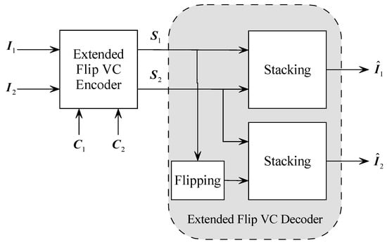
Figure 5.
Overall structure of the system. and are cover images, and are secret images, and are share images, and are recovered images.
These shares are distributed to two different participants. During decoding stage, after gathering two shares, The decoder is able to recover the content of the secret images by stacking operation. More specific, The content of secret image can be recovered by stacking and :
and the content of the secret image can be recovered by stakcing with the flipped
where is the flipping operation as defined in previous subsection.
We can recover the secret image that have the same information content as when stacking the front side of share with the front side of share . However, when we stack the front side of share and the reverse side of share , we can recover the secret image .
3.3. Determining Pixel Position
Let us assume in this section that the cover images are gray-scale images and the secret images are binary images. The grayscale cover image is of M rows and N columns. We divide the share images into blocks of size , and encode the 1-bit of (i.e., 1 pixel) secret image into block in the share images. So the size of the secret images has rows and columns, where returns the nearest integer towards the .
When stacking two shares in order to recover the secret image, two types of interference may appear:
- Interference from the cover images.
- Interference from the other secret image.
In order to recover secret images without interference, we must superimpose pixels that do not contain secret information in black. Let the matrix contain all the secret image pixels and the matrix contain all the auxiliary black pixels, where p is the index of the matrix of the secret image informations and q is the index of the share matrix. When recovering a secret image, in order to avoid interference of another secret image pixel, another secret pixel must be black after stacking. We define these pixels as auxiliary secret pixels .
In our algorithm, The positions for encoding the secret pixels are generated randomly. This random approach is advantageous than deterministic approaches in terms of security and ensuring the exact number of secret image pixels (SIP). The position determination algorithm is summarized in Algorithm 1.
We assume that each share image is segmented into blocks. Within each block, there are black pixels, which means that pixels are used for encoding the secret pixel from and pixels are used for encoding the secret pixel from .
When stacking two shares, we must use auxiliary black pixels (ABP) to remove the interference from the non-SIPs on stacking result. To ensure that we have enough ABPs, then number of ABPs should be at least half of the number of non-SIPS, i.e.,
| Algorithm 1 Determine pixel position |
| Input: |
| Q: Size of block. |
| : Size of the share image. |
| : The number of pixels in each secret image in a block. |
| : The number of black auxiliary pixels in a block. |
| Output: |
| and : Position matrix of pixel locations of secret image and secret image |
| pixels in the share image. |
| and : Position matrix of black auxiliary pixel position in share image and . |
| 1: for 1 to do |
| 2: for 1 to do |
| 3: Generate non-repeating random numbers from 1 to to form a sequence , |
| and map the sequence to a pixel block. |
| 4: Select the first random numbers and return their corresponding positions in the pixel block x(k), y(k), Where x(k) and y(k) represent the row and column positions of the kth random number in the pixel block, respectively. |
| 5: for m←1 to do |
| 6: |
| 7: end for |
| 8: for m← to do |
| 9: |
| 10: end for |
| 11: Select the random number after the th and return its corresponding position |
| x(k), y(k) in the pixel block. |
| 12: for m← to do |
| 13: |
| 14: end for |
| 15: for m← to end do |
| 16: |
| 17: end for |
| 18: end for |
| 19: end for |
| 20: Return the position matrices |
First, to determine the location for SIPs and non-SIPs, we generate a vector which contains a permutation of all integers between 1 and . Then we use the first numbers as positions of the SIPs for , and use the numbers as positions of the SIPs for . The positions are for ABPs in share , and the positions are for ABPs on share . Next, we map these positions into positions in a block, and fill the corresponding positions of with 1 and other positions with 0.
For example, let us take , then we have . Let us assume that the random permutation is
Then, the positions are used for embedding pixel from , and the positions are used to embed pixel from . The positions for ABPs on share and are and , respectively. Suppose that the current image block index is , then we get the following position matrices:
These positions are also illustrated in Figure 6.
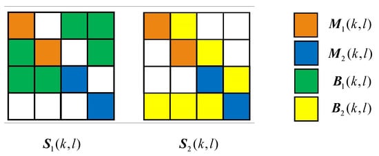
Figure 6.
Determining the locations of secret pixels and non-secret pixels().
3.4. Embedding the Secret Image into Shares
From the last subsection, we get a collection of secret pixel locations and non-secret pixel locations. In this section, we describe the process of embedding the secret information at the secret pixel locations. Since every block in the share contains two pieces of secret information and corresponds to another share in different ways, the secret pixel position needs special design when embedding the secret pixel.
In order to eliminate interference during stacking, we have to adjust the position matrices obtained from previous section before embedding secret pixels. The ABP matrix must meet the following two requirements
- When stacking and , the ABP matrix should cover the SIPs for the secret image ;
- When stacking and , the ABP matrix should cover the SIPs for the secret image .
So, we should adjust the position matrices as follows.
These positions on shares and are illustrated in Figure 7.
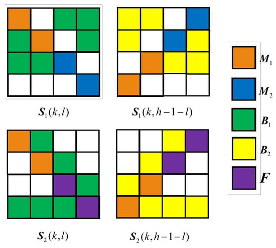
Figure 7.
Locations on shares after adjustment.
The basic matrices for bit 1 and bit 0 are denoted as and , respectively. For example, for a (2, 2) scheme, when , we let
That is, when the secret pixel is bit 0, then is selected and it is transformed into , where denotes column permutation. The first line of is filled into the corresponding secret pixel position in share 1, and the second row is filled in the corresponding secret pixel in share .
Now that we know how to embed a secret bit, then we can embed the whole secret image into the shares. First, we embed the bits from . The other block index is (k,l), which is also the pixel index of the secret pixel. If the pixel in is 0, we need to fill the lines of into the corresponding positions in the two shares, otherwise we fill in . Next, the bits from is embedded based on the information of . If the bit of is 0, we fill in the complement of the position information in into the position in . Instead, the location information is copied. Finally, fill the auxiliary secret pixel and the auxiliary black pixel position with the bit 1.
3.5. Embed Cover Image In Share
The above section describes the process of embedding two secret images into two shares. The share obtained through this process is meaningless. In this section, we use constraint error diffusion to embed the cover image into the shares [], making the shares meaningful. The pixels in the share image are sequentially scanned using the raster scanning order. The cover image is quantized and embedded into the share image. The quantization process can be expressed as
where , , and are the position matrices obtained from previous sections. The first term in the summation says that for those positions carrying the SIPs and ABPs, we leave them unchanged during cover image embedding process. The second terms says that for those positions allocated for carrying cover image, we use a simple binary quantizer:
To achieve better visual quality for the share images, the error between the share images and the cover images is spread to the non-secret information positions and the non-auxiliary positions by the error diffusion. Error diffusion diffuses the error produced by quantization at current location to its neighbors, so that when quantizing these neighboring pixels, these errors can be compensated. A diffusion kernel is like a filter kernel that determines how the errors are allocated to its neighbors [].
Let be the diffusion kernel located in the pixel (k, l), then in the constrained diffusion, the modified diffusion coefficient is . That is, the diffusion coefficient is set to 0 at the and and positions.
4. Flip Visual Cryptography for Color Images
Color visual cryptography has better visual quality than its gray-scale counterpart since it can render more details with colors. In this section, we design a color VC in RGB color space. The secret image is divided into three channels of R, G, and B, and the secret image is embedded into the share image according to the principle of color stacking. The color overlay model is shown in Figure 8.
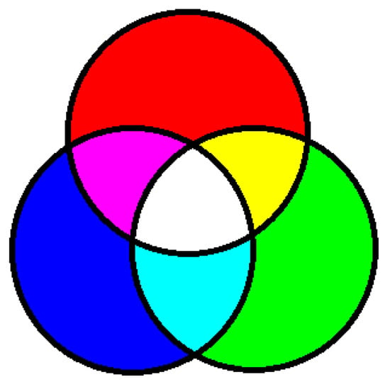
Figure 8.
Color overlay model for RGB color space.
Our color VC is based on the human perception of color. When different pixels having different colors are clustered then our HVS (Human Visual System) perceives and average color. For example, if four pixels having color R, G, B, and W (R: red, G: green, B: blue, and W: white) are arranged as a block, then we perceive white. Similarly, the effect of other colors can be achieved according to the proportion of colors in a small block. For example, if we have two B, one R and one G, then the ratio of the R, G, and B colors that are shared by the two shares is , and the perceived color is blue. We can get different proportions of different colors after superimposing the sharing of different colors, as shown in Figure 9.
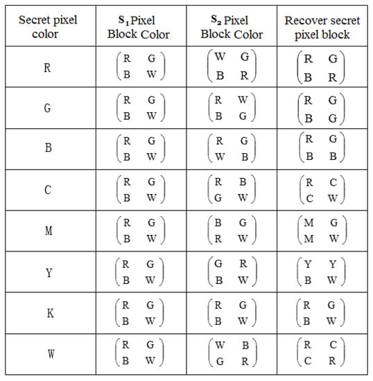
Figure 9.
Color sub-channel visual cryptography scheme.
The steps to embed a secret image in a share during the color visual cryptography process are as described as follows:
- Step 1: Color decomposition and halftoning. The RGB color image channels of and are separately halftoned.
- Step 2: Embed R, G, B, W at the secret information 1 position in the (k, l), where (k, l) denotes the position of the pixel block, where .
- Step 3: Embed the corresponding color in the secret information position of the (i, j) pixel block according to the color of (i, j) and the color of (i, j) position corresponding to secret information .
- Step 4: Embed in the secret information position of the pixel block at (i, N + 1 −j) position according to the color of (i, N + 1 −j) and the color of the secret information 1 of (i, j) pixel block.
- Step 5: Embed R, G, B, and W at the secret information position in (i, N + 1 − j) position pixel block.
- Step 6: Fill in secret information position of (i, N + 1 −j) pixel block according to the color of (i, N + 1 −j) and the color of secret information 1 in (i, N + 1 − j) pixel block.
- Step 7: According to the color of (i, j) and the color of secret information in (i, N + 1 −j) pixel block, fill in the corresponding color of the secret information position in (i, j) pixel block.
5. Experiments
5.1. Experiment for Gray-Scale Image
In this section, we show the experimental results for gray-scale cover images. The parameters used for the experiment are and . In order to measure the visual quality of the share images, we use the MSSIM (Mean Structural Similarity Measure) and PSNR (Peak Signal-to-Noise Ratio) metrics. The diffusion mask is the Floyd—Steinberg mask in experiments. The two cover images and two secret images are shown in Figure 10.

Figure 10.
The images used in the experiment. (a–d) are cover image , cover image , secret image , and secret image , respectively.
The share images obtained from the proposed algorithm are shown in Figure 11. Before calculating image quality, Gaussian filtering is performed on the halftone image of the cover images and the share images. This Gaussian filtering simulates the low-pass property of the HVS. The PSNRs for the two share images are 16.3478 and 13.8942, respectively. The MSSIM measures are 0.6584 and 0.6196, respectively.
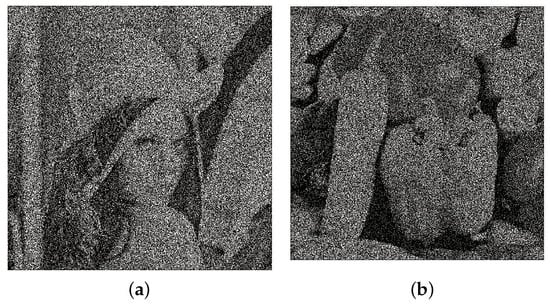
Figure 11.
The generated meaningful shares. (a,b) are share image , share image , respectively. The corresponding PSNR values are 16.3478 and 13.8942, respectively.
The superimposed results of the two share images are shown in Figure 12. Among them, Figure 12a is stacking result of Figure 11a,b. Figure 12b is the stacking result of the front side of Figure 11a and the reverse side of Figure 11b.
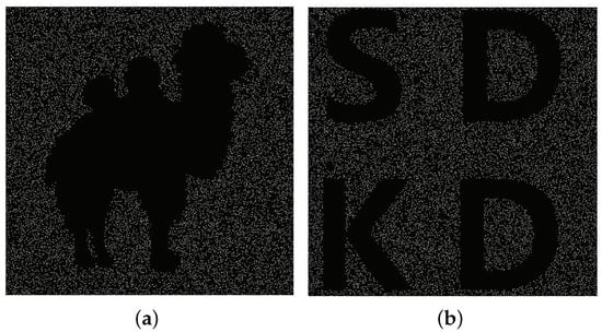
Figure 12.
The superimposed results of the two share images. (a) The recovered secret image 1. (b) The recovered secret image 2.
In order to test if the proposed algorithm is applicable to various types of images, we performed a batch test on ten standard testing images. Figure 13 shows the gray-scale cover images and Figure 14 shows the secret images. In our experiment, different images are selected as the cover images, and the corresponding binary image with the same size as cover images are used as the secret image. The binary secret images are randomly chosen from a set of 18 binary images. The grayscale cover images are randomly chosen from a set of 18 grayscale images. If the size of the secret image is too large or too small, it is resized so that it is suitable for the cover image. To resize the binary image, we found that the nearest interpolation method gives a reasonably good result. Then, we use the simple binary thresholding to convert the gray-scale image to a binary image. PSNR and MSSIM metrics are used to measure the visual quality of the share images.
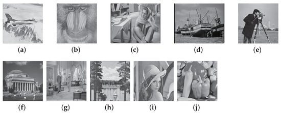
Figure 13.
A collection of cover images in batch test. (a–j) are samples of the cover images.
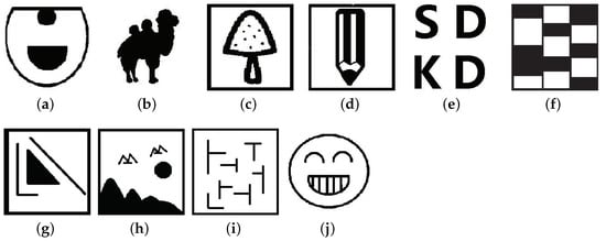
Figure 14.
A collection of secret images in batch test. (a–j) are samples of the secret images.
5.1.1. Feasibility Experiment for Gray-Scale Cover Images
For the batch test, the variance of the Gaussian filter is set to 4 and the kernel size is . Table 1 shows the values of the PSNR and MSSIM values for some images in the batch test.

Table 1.
The values of PSNR and MSSIM for some images in the batch test. The images kodim01 to kodim18 are cover images, and the binary images binary1 to binary18 are secret images.
It can be seen from Table 1 that, the values of PSNR and MSSIM in the image experiment do not fluctuate much, indicating that our algorithm performs well and consistent for different cover images and secret images. The contrast of the recovered secret image is the same as in []. The cover image, which is also halftoned before encryption, is Gaussian filtered and compared with the share image. In this paper, the compared cover image information in each pixel block of the share image accounts for , while in [], the compared cover image information in each pixel block of the share image accounts for . Therefore, the contrast of our flip VC is only slightly inferior to [], but visually quite similar.
The time complexity of our algorithm is tested in terms of machine time. The machine time of each experiment is affected by the location of the image pixels and the random distribution of the secret information. That is to say, because the pixel positions of each image are different and the pixel positions are randomly distributed when the secret information is embedded, the machine time of each image experiment is also different. The machine time of each experiment in the batch experiment is shown in Figure 15.
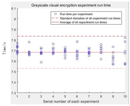
Figure 15.
Machine time in batch test.
According to the chart, it can be seen that the machine time of the algorithm has nothing to do with the content of the image, it is only related to the size of the image, all floating around the average. At the same time, it can be seen that the short machine time of the algorithm is generally about 7.7 s, indicating that the algorithm is simple to run, high in efficiency, and easy to apply.
5.1.2. Security Analysis
This section analyzes the security of our algorithm. We show that it is not possible to infer the secret image from just one share. Each block in the share image contains two secret image bits and two cover image bits, each of which has the same proportion of secret image information. At the same time, the position of each pixel information is random. In Figure 16, we list the position distribution of the corresponding pixel blocks in the share image between the secret image and the secret image . The five cases are listed among all the possibilities. Among them, and are secret images, is a pixel index of the secret image, is a share image, and is a block index corresponding to the secret image . Each position situation has the same probability.

Figure 16.
The distribution of secret image bits in the share image pixel block (five in all cases).
The secret information in the corresponding pixel block in the share image is obtained by the random column transformation of the basic matrix. The probability of each position situation in the picture is the same. so the secret information in the pixel block cannot be determined. Therefore, even if someone obtains one of the share images, the secret image information cannot be obtained from it. Therefore, the system build using our algorithm is secure.
In our algorithm, the share images use a random allocation method to embed the secret image and the cover image. So, the attacker cannot copy the secret information and the black auxiliary information location without knowing the allocation location. An attacker can only change any pixel information in a pixel block. However, under this attack, the secret image can still be recovered. Therefore, the proposed algorithm is also robust to attacks.
5.2. Experiments for Color Images
In this section, we show the experimental results for color cover images. The parameters used for the experiment are and . In order to measure the quality of the share images, we apply the MSSIM and PSNR parameters. The diffusion kernel is the Floyd—Steinberg mask in experiments. The two cover images and two secret images are shown in Figure 17.

Figure 17.
The images used in the experiment. (a–d) are cover image , cover image , secret image , and secret image , respectively.
The color flip visual cryptography experiment is similar to the gray-scale flip visual cryptography. When the two share images are superimposed on the front side, the secret image is recovered. After the share image is flipped and the share image is stacked, we obtain the secret image . The experimental result is shown in Figure 18.
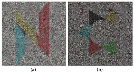
Figure 18.
The generated meaningful shares. (a,b) are share image1 and share image2 , respectively. PSNR values are 3.5139 and 2.5697, respectively.
The secret image recovery result is shown in Figure 19, where Figure 19a is the recovery secret image , and Figure 19b is the recovery secret image .
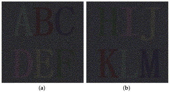
Figure 19.
The superimposed results of the two share images. (a) The recovered secret image 1. (b) The recovered secret image 2.
Testing Contrast
According to the algorithm principle of the previous chapter, when the two share images are superimposed to generate a secret image, the recovered black color is biased, not pure black, but a black-like color displayed by mixing cyan and red through the human eye system. At the same time, because the secret pixel information in each pixel of the share image is relatively small, the visual quality of the recovered secret image is dark. The size of each pixel block in the paper is . According to the principle of visual cryptography and overlay, it can be concluded that only 4 pixels in the share image pixel block are one of the secret image information. The color obtained by superimposing the secret image information is a mixture of colors, so only two pixels in each share image pixel block are secret image information colors. That is, the contrast of the share image with respect to the cover image is 1/8.
Because the pixel block in each superimposed recovered secret image includes information auxiliary pixels and black auxiliary pixels, and each auxiliary pixel is a black pixel, the entire recovered secret image is displayed black, and the black and white information of the secret image is not obvious. Because 3/4 of the pixel blocks in each share are superimposed with black pixels and white pixels are mixed with four colors of R, G, B, and W, the superimposed white pixels are relatively dark and cannot be used. This analysis shows that black and white pixels in a secret image can be distinguished in a recovered image.
According to the above analysis, each color in the recovered secret image has the same proportion in the block, so the brightness is the same. However, the restored images of different colors have different visual quality, objectively because the color contrast of each color and the background black is different, so each recovered secret image has a different visual quality.
Because the recovered secret images have the same brightness, we cannot objectively evaluate which color has the best visual quality, so we performed a series of subjective evaluations. First, we use the image in Kodak as a cover image and combine different letters or numbers to form a secret image for encryption. Each secret image has six different colors: red, green, blue, cyan, magenta, and yellow. In order to print the image with better visual quality, we set the size of each secret image to , then cover up the image size to , and print the image with 600 dpi (dots per inch) to get a larger image, which is easier for visual inspection. Secondly, the different colors of each secret image are encrypted and superimposed to recover the secret image. The recovered secret image has a dpi of 600 and a size of two inches (5.08 cm). Finally, the different color overlay results of each secret image are printed on a piece of paper. In order to avoid the human eye’s adaptation to their color differences, each experiment is repeated for a different participant. The participant is asked to be exposed to the test image for 5 s and is asked to scale the quality. These subjective rankings are then counted, and the final ranking obtained according to the principle of majority voting is used as the final subjective evaluation data. After the above experimental process, we finally get the subjective judgment results of recovering the secret image from good to bad, which are blue, red, cyan, yellow, magenta, and green, respectively. Figure 20 shows the results of a set of experiments in a batch experiment. We can sort the following experiments according to the above process.
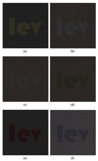
Figure 20.
Contrast main observation evaluation chart. (a) Yellow. (b) Cyan. (c) Magenta. (d) Green. (e) Red. (f) Blue.
5.3. Comparison with Other Algorithm
In our design, we apply the following restrictions to our algorithms:
- Meaningful shares;
- Simple decoding without calculation;
- No interference from cover images on stacking result;
- Applicable to color cover images.
Our experimental test verified that these requirements are met simultaneously by our design. For a fair comparison with existing algorithms, we focus on the type where no computation is needed in the decoding stage [,,,,]. Among these algorithms, Lin’s proposal is closely related to our proposal since both of these two belongs to flip VC []. Compared with Lin’s algorithm, our algorithm applies to color cover images and produces meaningful shares, where Lin’s algorithm is designed for binary secret image and it produces meaningless shares. In terms of computational complexity, our algorithm is slightly higher than Lin’s algorithm because local error propagation is a neighborhood operation, while encoding in Lin’s algorithm is point-wise. However, both algorithms have a complexity which scales linearly with the number of pixels in secret image.
Similar to our proposal, Fang’s algorithm also hides a second secret image in shares which can be decoded by stacking one share with a shifted version of the other share []. However, Fang’s algorithm is not directly applicable to color cover images and it produces meaningless shares. Furthermore, Fang’s algorithm is not size-invariant so that each share image is four times larger than the secret images. In contrast, our algorithm is size-invariant. Our algorithm has a higher complexity since both the secret images and the cover images needs to be consider during encoding stage. This is the price we have to pay for added function.
Yan’s algorithm hides a second secret image in meaningful shares []. But unfortunately, it is not directly applicable to color secret images. Yan’s algorithm have a similarity complexity as our algorithm since both of them are based on constrained error diffusion. Wang’s algorithm produces meaningful shares but is also not directly applicable to color secret images []. Furthermore, Wang’s algorithm hides only one secret image, while our algorithm hides two. In terms of complexity, our algorithm has a slightly higher complexity than Wang’s due to the added functions.
Lou’s algorithm applies to color secret images, but the stacking image has interference from the cover images []. This makes the decoding of fine details in the secret image more difficult. In contrast, our algorithm can guarantee a clean stacking result, i.e., no interference from cover images. Both Lou’s algorithm and the proposed algorithm scale linearly with the number of pixels in the secret image.
We summarize the above comparison and analysis in Table 2. It is evident that our algorithm is the only one that meets these requirements simultaneously.

Table 2.
Comparison with related papers.
6. Conclusions
Based on the principle of the VC system, this paper constructs an extended VC system that can embed two secret images on two color cover images. Constraint error diffusion is designed to embed two secret images during the halftoning process. The two secret images are restored by flipping the overlay, and the secret images do not interfere with each other. Experiments show that there is a trade-off between the restoration of secret images and share images. Compared with other related papers, this paper has the better visual quality and good image quality. Our work also demonstrates that joint VC encrypting and halftoning is promising in improving the visual quality of the share images.
Author Contributions
Conceptualization, L.W., B.Y., J.-S.P. and H.-M.Y.; software, L.W., B.Y.; Methodology, J.-S.P., H.-M.Y.; Writing—original draft, L.W., B.Y., J.-S.P. and H.-M.Y.; Writing—review & editing, H.-M.Y. All authors have read and agreed to the published version of the manuscript.
Funding
This work was funded by the the National Natural Science Foundation of China (NSFC) (No. 61272432), Shandong Provincial Natural Science Foundation (No. ZR2014JL044), and MOE (Ministry of Education in China) Project of Humanities and Social Sciences (Project No. 18YJAZH110).
Informed Consent Statement
Not applicable.
Data Availability Statement
The data presented in this study are available on request from the corresponding author. The data are not publicly available due to privacy.
Acknowledgments
The authors would like to thank Molefi Itumeleng Alice for proof-reading the whole manuscript.
Conflicts of Interest
The authors declare no conflict of interest.
References
- Weng, S.; Zhang, C.; Zhang, T.; Chen, K. High capacity reversible data hiding in encrypted images using SIBRW and GCC. J. Vis. Commun. Image Represent. 2020, 102932. [Google Scholar] [CrossRef]
- Cai, H.L.; Yan, B.; Pan, J.S.; Ye, J.L. Print-Scan Resistant Two-Level QR Code. J. Inf. Hiding Multimed. Signal Process. 2019, 10, 300–312. [Google Scholar]
- Yan, B.; Chen, N.; Yang, H.M.; Hao, J.J. Local blackness preserving visual cryptography for grayscale secret images. J. Inf. Hiding Multimed. Signal Process. 2018, 9, 370–382. [Google Scholar]
- Naor, M.; Shamir, A. Visual Cryptography. In Proceedings of the Workshop on the Theory and Application of Cryptographic Techniques (EUROCRYPT’94), Perugia, Italy, 9–12 May 1994; pp. 1–12. [Google Scholar]
- Sharma, R.G.; Dimri, P.; Garg, H. Visual cryptographic techniques for secret image sharing: A review. Inf. Syst. Secur. 2019, 27, 241–259. [Google Scholar] [CrossRef]
- Yang, C.N.; Laih, C.S. New Colored Visual Secret Sharing Schemes. Des. Codes Cryptogr. 2000, 20, 325–336. [Google Scholar] [CrossRef]
- Mhala, N.C.; Jamal, R.; Pais, A.R. Randomised visual secret sharing scheme for grey-scale and colour images. IET Image Process. 2018, 12, 422–431. [Google Scholar] [CrossRef]
- Chen, S.K. Friendly progressive visual secret sharing using generalized random grids. Opt. Eng. 2009, 48, 117001. [Google Scholar] [CrossRef]
- Hou, Y.C.; Quan, Z.Y. Progressive Visual Cryptography With Unexpanded Shares. IEEE Trans. Circuits Syst. Video Technol. 2011, 21, 1760–1764. [Google Scholar] [CrossRef]
- Wang, R.Z. Region Incrementing Visual Cryptography. IEEE Signal Process. Lett. 2009, 16, 659–662. [Google Scholar] [CrossRef]
- Yang, C.N.; Chung, T.H. A general multi-secret visual cryptography scheme. Opt. Commun. 2010, 283, 4949–4962. [Google Scholar] [CrossRef]
- Dewi, R.; Sari, P.K. The Improvement of Flip (2,2) Visual Cryptography Images Using Two Key Images. ComTech Comput. Math. Eng. Appl. 2016, 7, 213. [Google Scholar] [CrossRef][Green Version]
- Abdul, W.; Ali, Z.; Ghouzali, S.; Alfawaz, B.; Muhammad, G.; Hossain, M.S. Biometric Security Through Visual Encryption for Fog Edge Computing. IEEE Access 2017, 5, 5531–5538. [Google Scholar] [CrossRef]
- Cimato, S.; Prisco, R.D.; Santis, A.D. Probabilistic Visual Cryptography Schemes. Comput. J. 2006, 49, 97–107. [Google Scholar] [CrossRef]
- Guo, T.; Liu, F.; Wu, C. Threshold visual secret sharing by random grids with improved contrast. J. Syst. Softw. 2013, 86, 2094–2109. [Google Scholar] [CrossRef]
- Nakajima, M.; Yamaguchi, Y. Extended Visual Cryptography for Natural Images. J. WSCG 2002, 10, 303–310. [Google Scholar]
- Liu, F.; Wu, C. Embedded Extended Visual Cryptography Schemes. IEEE Trans. Inf. Forensics Secur. 2011, 6, 307–322. [Google Scholar] [CrossRef]
- Bao, L.; Zhou, Y. Image encryption: Generating visually meaningful encrypted images. Inf. Sci. 2015, 324, 197–207. [Google Scholar] [CrossRef]
- Kanso, A.; Ghebleh, M. An algorithm for encryption of secret images into meaningful images. Opt. Lasers Eng. 2017, 90, 196–208. [Google Scholar] [CrossRef]
- Hsiao, C.Y.; Wang, H.J. Enhancing image quality in Visual Cryptography with colors. In Proceedings of the International Conference on Information Security and Intelligence Control, Yunlin, Taiwan, 14–16 August 2012. [Google Scholar]
- Pahuja, S.; Kasana, S.S. Halftone visual cryptography for color images. In Proceedings of the International Conference on Computer, Jaipur, India, 1–2 July 2017; pp. 281–285. [Google Scholar]
- Hou, Y.C. Visual cryptography for color images. Pattern Recognit. 2003, 36, 1619–1629. [Google Scholar] [CrossRef]
- Prakash, N.K.; Govindaraju, S. Visual cryptography scheme for color images using halftoning via direct binary search with adaptive search and swap. Int. J. Comput. Electr. Eng. 2011, 3, 900. [Google Scholar] [CrossRef][Green Version]
- Yan, B.; Xiang, Y.; Hua, G. Improving Image Quality in Visual Cryptography; Springer Nature Singapore Pte Ltd.: Singapore, 2019. [Google Scholar]
- Lin, S.J.; Chen, S.K.; Lin, J.C. Flip visual cryptography (FVC) with perfect security, conditionally-optimal contrast, and no expansion. J. Vis. Commun. Image Represent. 2010, 21, 900–916. [Google Scholar] [CrossRef]
- Yan, B.; Wang, Y.F.; Song, L.Y.; Yang, H.M. Size-invariant extended visual cryptography with embedded watermark based on error diffusion. Multimed. Tools Appl. 2016, 75, 11157–11180. [Google Scholar] [CrossRef]
- Fang, W.P.; Lin, J.C. Visual cryptography with extra ability of hiding confidential data. J. Electron. Imaging 2006, 15, 023020. [Google Scholar] [CrossRef][Green Version]
- Wang, Z.; Arce, G.R.; Crescenzo, G.D. Halftone Visual Cryptography Via Error Diffusion. IEEE Trans. Inf. Forensics Secur. 2009, 4, 383–396. [Google Scholar] [CrossRef]
- Lou, D.C.; Chen, H.H.; Wu, H.C.; Tsai, C.S. A novel authenticatable color visual secret sharing scheme using non-expanded meaningful shares. Displays 2011, 32, 118–134. [Google Scholar] [CrossRef]
Publisher’s Note: MDPI stays neutral with regard to jurisdictional claims in published maps and institutional affiliations. |
© 2020 by the authors. Licensee MDPI, Basel, Switzerland. This article is an open access article distributed under the terms and conditions of the Creative Commons Attribution (CC BY) license (http://creativecommons.org/licenses/by/4.0/).