Article

Optimal Beacon Placement for Self-Localization Using Three Beacon Bearings

1
University of South Australia, Mawson Lakes, SA 5095, Australia
2
Joint and Operations Analysis Division, Defence Science and Technology Group, Melbourne, VIC 3207, Australia
*
Author to whom correspondence should be addressed.
Symmetry 2021, 13(1), 56; https://doi.org/10.3390/sym13010056
Submission received: 9 December 2020 / Revised: 23 December 2020 / Accepted: 28 December 2020 / Published: 31 December 2020

Abstract

:
Autonomous vehicles need to localize themselves within the environment in order to effectively perform most tasks. In situations where a Global Navigation Satellite System such as the Global Positioning System cannot be used for localization, other methods are required. One self-localization method is to use signals transmitted by beacons at known locations to determine the relative distance and bearing of the vehicle from the beacons. Estimation performance is influenced by the beacon–vehicle geometry and the investigation into the optimal placement of beacons is of interest to maximize the estimation performance. In this article, a new solution to the optimal beacon placement problem for self-localization of a vehicle on a two-dimensional plane using angle-of-arrival measurements is proposed. The inclusion of heading angle in the estimation problem differentiates this work from angle-of-arrival target localization, making the optimization problem more difficult to solve. First, an expression of the determinant of the Fisher information matrix for an arbitrary number of beacons is provided. Then, a procedure for analytically determining the optimal angular separations for the case of three beacons is presented. The use of three beacons is motivated by practical considerations. Numerical simulations are used to demonstrate the optimality of the proposed method.

1. Introduction

Autonomous vehicles usually require accurate estimation of their position and heading in a global coordinate system to effectively accomplish mission objectives. Global Navigation Satellite Systems (GNSS) such as the Global Positioning System (GPS) are widely used for localization. GNSS is not a viable localization solution in situations where line-of-sight communication with the navigation satellites is interrupted (e.g., indoor operation, or when the satellite signals are likely to be jammed). GNSS is also unsuitable for use in low-power systems that lack sufficient hardware capability [1]. When GNSS is impractical, an alternate localization approach is necessary, such as using signals transmitted by a set of beacons to determine relative distances and bearings. An example of localization using beacon measurements is angle-of-arrival (AoA) localization. AoA localization is a technique for determining the position of an emitter by triangulating bearing measurements received from multiple sensors. Bearing measurements can be acquired passively and can provide distance and orientation information [2,3], which makes them useful in applications such as self-localization. For self-localization, a vehicle uses AoA measurements from multiple transmitters to estimate its position and heading. The relative placement of the receiver and transmitters affects AoA estimation accuracy [4]. Investigating geometries that yield the best estimation accuracy provides useful insight into the optimal path an Unmanned Aerial Vehicle (UAV) should take in an optimal path-planning application [5].
For the AoA self-localization problem, the objective is to place the beacons to produce an optimal estimate of the two-dimensional (2D) position and heading of a vehicle from the measured beacon bearings (see, e.g., [6,7]). The optimal beacon placement is realized by positioning beacons at fixed but arbitrary distances from the UAV and selecting the beacon angular separations that minimize estimation uncertainty. Including the vehicle heading into the optimization problem greatly increases the difficulty of finding an analytical solution when compared to AoA target location estimation. We propose a new solution to the optimal placement of three beacons for self-localization using AoA measurements. Three beacons are the minimum sized constellation required for complete 2D localization [8], and thus the least expensive and the easiest deployed. It is desirable to limit the number of beacons used in many applications, such as underwater self-location using an acoustic positioning system.
Acoustic positioning systems such as the Long Baseline system (LBL) are an alternative to GNSS technology for self-location in underwater environments. GNSS technology is unsuitable for this application as electromagnetic signals from the satellites’ experience strong attenuation in water. LBL schemes use acoustic transponders placed on the seabed that act as beacons to self-locate [9]. These systems have been designed to work with as few as a single beacon to reduce the logistics associated with deploying more beacons [9,10]. Minimizing the number of localization beacons allows for energy conservation in communication and reduces computational complexity [11], motivating the use of three beacons.
For RF self-localization, the beacons operate at different frequencies. Including more beacons in the self-localization architecture requires a larger receiver bandwidth, resulting in increased hardware cost. The cost of including extra beacons is substantial if mobile beacons are considered. Providing mobility to beacons requires mounting them on vehicles with GNSS capability and the power capacity to provide transmission [12]. There are restrictions on the number of vehicles available to operate as a mobile beacon in resource-constrained applications. In these applications, it is useful to know the optimal configuration that uses the minimum amount of resources. When many beacons are present, the algorithm can be used to evaluate the subset of beacons that are closest to an optimal placement or require the lowest cost to configure optimally. In summary, the motivation for using three beacons is as follows. Using the minimum number of beacons for self-localization leads to reduced costs, placement logistics, computational complexity, and energy required for communication.
To the best of our knowledge, no optimal beacon geometry analysis for position and orientation self-localization using AoA measurements has been hitherto reported in the open literature.
In this article, we present an analytical solution to the optimal beacon placement problem for self-localization of a vehicle on a two-dimensional plane using angle-of-arrival measurements.
The key contributions of the study are:
  • A simplified expression for the determinant of the FIM for vehicle self-localization using AoA measurements for an arbitrary number of beacons.
  • An analytical method for calculating angular separations between beacons that satisfy the D-optimality criterion when three beacons are used.
  • A mathematical proof that our solution satisfies the sufficient and necessary conditions for optimality.
  • Simulations that confirm the optimality of the proposed approach.
The rest of this article is organized as follows. Related work is discussed in Section 2. The problem is introduced, and the determinant of the FIM is expressed in Section 3. Analysis of MSE and the FIM is undertaken in Section 4, including discussion of the complexity of the optimization problem and the introduction of several different forms for the objective function. The specific case of three beacons and one vehicle is introduced, and an analytical solution is formulated in Section 5. The results of numerical simulations used to verify the optimality of the proposed approach are presented in Section 6, and a conclusion is presented in Section 7.

2. Related Work

Placing beacons to minimize self-localization uncertainty is similar to placing sensors for minimizing target location estimation error. For target location estimation, multiple sensors are placed rather than beacons, and only position estimation uncertainty is minimized. In both applications, optimal geometries are realized by placing sensors or beacons such that some scalar objective function is either maximized or minimized [13]. The same process can be used to determine optimal trajectories for mobile sensors and beacons [5]. The objective functions are selected such that their optimization results in estimation error minimization, and they are usually based on the Cramér–Rao lower bound (CRLB) of the estimator or the Fisher information matrix (FIM). Popular objective functions include the D-optimality criterion and the A-optimality criterion.
The D-optimality criterion maximizes the determinant of the FIM and thus minimizes the volume of the confidence ellipsoid for the localization estimates [13]. The D-optimality criterion has been used in stationary bearings-only target localization [4,5,14], and to develop trajectories for localizing stationary targets [15,16] and maneuvering targets [17,18,19]. The A-optimality criterion minimizes the trace of the inverse FIM, which minimizes the mean squared error (MSE) of the estimates. The A-optimality criterion has been used to determine optimal flight paths for multiple UAVs using AoA measurements to localize a stationary target [20,21] or a moving target [22,23,24], and for 3D AoA target localization [25,26]. The diversity of the eigenvalues of the FIM has been used as an alternative criterion for the optimal placement of sensors for target position estimation [27]. In two dimensions, it produces the same result as using the D-optimality criterion.
An advantage of the D-optimality criterion over the A-optimality criterion is that it does not depend on the scale of the variables [28,29]. This advantage is beneficial for the application presented as the vehicle states are position and heading. The optimal geometries produced using the A-optimality criterion would be dependent on the units of measurement, unlike those produced using D-optimality.

3. Problem Definition

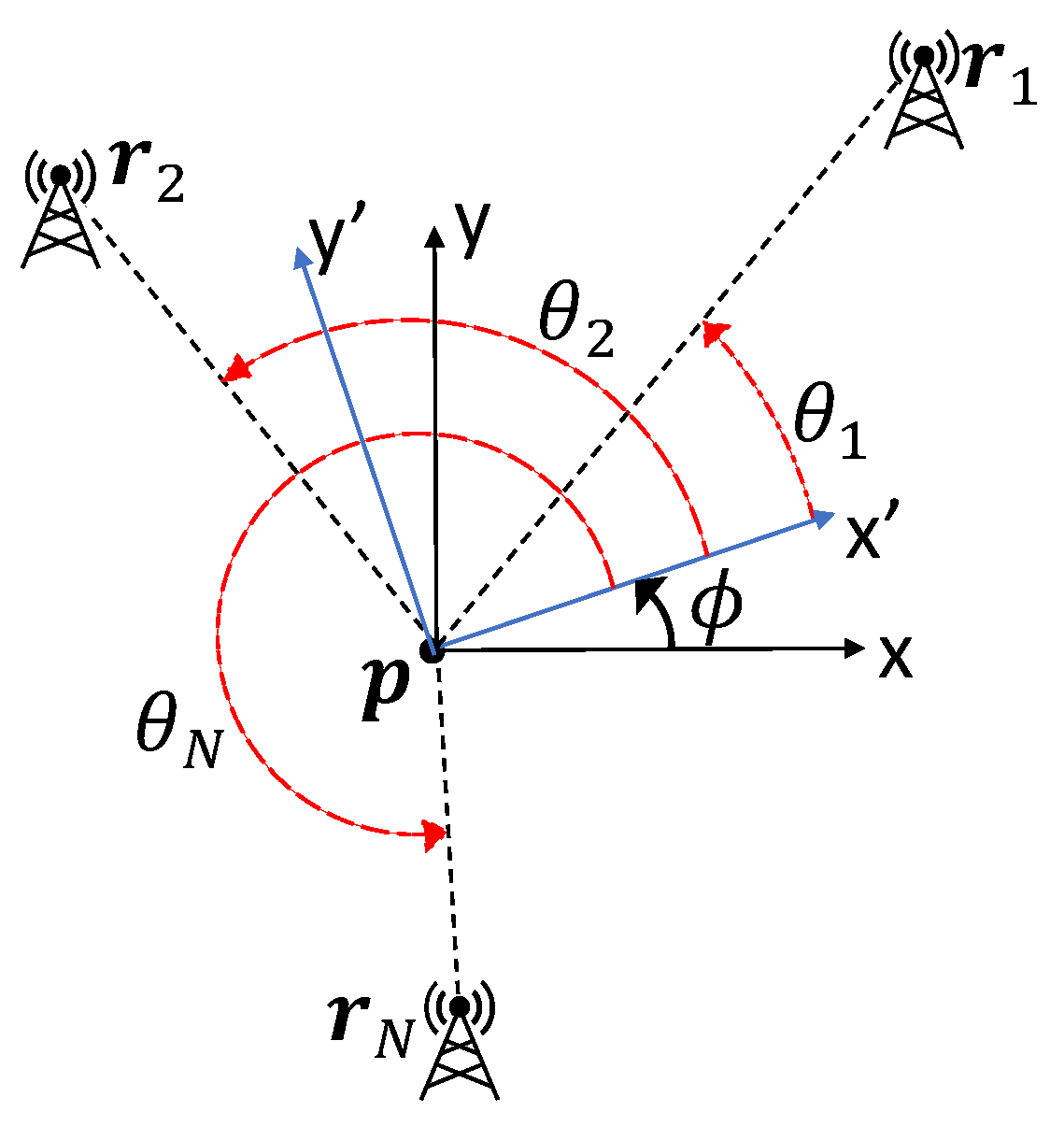
Consider the self-localization geometry in Figure 1. The objective is to determine the relationship between the beacon bearings in the global coordinates ϕ + θ 1 , ϕ + θ 2 , …, ϕ + θ N to optimize the estimates of p and ϕ for given and fixed beacon distances from the platform d i = | | p r i | | , i = 1 , 2 , , N for N 3 . Here, ϕ is the vehicle heading, p is the vehicle position, θ i is the relative bearing angle between the vehicle heading, and the ith beacon and r i is the position of the ith beacon.
The position and heading estimation problem is formulated as an optimization problem. The optimization criterion adopted for this work is the D-optimality criterion, chosen because it is invariant under scale changes in the parameters [28]. Assuming that the beacon bearing measurements are corrupted by i.i.d. zero-mean Gaussian bearing noise with covariance Σ = diag ( σ 1 2 , σ 2 2 , , σ N 2 ) , the FIM is given by
Φ = J 0 Σ 1 J 0 ,
where J 0 is the Jacobian matrix:
J 0 = sin ( θ 1 + ϕ ) | | p r 1 | | cos ( θ 1 + ϕ ) | | p r 1 | | 1 sin ( θ 2 + ϕ ) | | p r 2 | | cos ( θ 2 + ϕ ) | | p r 2 | | 1 sin ( θ N + ϕ ) | | p r N | | cos ( θ N + ϕ ) | | p r N | | 1 .
If all of the beacons and the vehicle are co-linear or co-circular, no unique estimate exists, making the Cramér–Rao lower bound CRLB (inverse of FIM) tend to infinity and the determinant of the FIM to zero [7,8,30]. In block matrix form, the FIM can be written as
Φ = A b b c ,
where
A = i = 1 N 1 γ i sin ( ϑ i ) 2 i = 1 N 1 γ i sin ( ϑ i ) cos ( ϑ i ) i = 1 N 1 γ i sin ( ϑ i ) cos ( ϑ i ) i = 1 N 1 γ i cos ( ϑ i ) 2 ,
b = i = 1 N d i γ i sin ( ϑ i ) i = 1 N d i γ i cos ( ϑ i ) , c = i = 1 N 1 σ i 2 , γ i = σ i 2 d i 2 , ϑ i = θ i + ϕ .
The D-optimality criterion can be used to place beacons for optimal self-localization. The D-optimality criterion selects the beacon angular positions that maximize the determinant of the FIM. Maximizing the determinant of the FIM minimizes the volume of the confidence ellipsoid for the self-localization estimate. The D-optimality criterion is
max ϑ 1 , ϑ 2 , , ϑ N | Φ | ,
where | Φ | denotes the determinant of Φ . Since the FIM is a block matrix, its determinant can be expressed as [31]
| Φ | = c 1 | A c b b | .
This optimization problem is nontrivial because | Φ | has a rather complicated expression involving the multiplication of sums of sines and cosines. In the following section, a simplification of the expression for | Φ | for the three-beacon case is presented, followed by a generalization to any number of beacons. For simplicity, we assume all the bearing measurements have the same variance, i.e., σ i 2 = σ 2 , i = 1 , , N .

4. Analysis of Mean Square Error and Determinant of Fisher Information Matrix

The CRLB is the inverse of the FIM:
1 | Φ | A 22 c b 2 2 A 12 c + b 1 2 A 12 b 2 A 22 b 1 A 21 c + b 2 b 1 A 11 c b 1 2 A 11 b 2 + A 21 b 1 A 21 b 2 A 22 b 1 A 11 b 2 + A 12 b 1 A 11 A 22 A 12 A 21 ,
where A i j is the { i j } th entry of A and A 21 = A 12 . The MSE is given by the trace of the CRLB [5]:
A 22 c b 2 2 + A 11 c b 1 2 + A 11 A 22 A 12 A 21 | Φ | = 1 | Φ | σ 4 { N i = 1 N 1 d i 2 i = 1 N sin ( ϑ i ) d i 2 i = 1 N cos ( ϑ i ) d i 2 + 1 4 i = 1 N 1 d i 2 2 1 4 i = 1 N sin ( 2 ϑ i ) d i 2 2 1 4 i = 1 N cos ( 2 ϑ i ) d i 2 2 } .
It is evident from the above expression that the beacon geometry that maximizes | Φ | does not necessarily minimize the MSE, unlike the case for the bearings-only localization problem [5]. Therefore, the A-optimality criterion (which minimizes the MSE directly) and the D-optimality criterion adopted here will produce different optimal geometries. Turning our attention to the D-optimality criterion, the expression for | Φ | for the case of N = 3 can be simplified to
| Φ | = sin ( ϑ 2 ϑ 3 ) σ 3 d 2 d 3 + sin ( ϑ 1 ϑ 2 ) σ 3 d 1 d 2 + sin ( ϑ 3 ϑ 1 ) σ 3 d 1 d 3 2 ,
the optimization problem becomes
max ϑ 1 , ϑ 2 , ϑ 3 sin ( ϑ 2 ϑ 3 ) d 2 d 3 + sin ( ϑ 1 ϑ 2 ) d 1 d 2 + sin ( ϑ 3 ϑ 1 ) d 1 d 3 2 .
An analytical solution to this optimization problem will be developed in Section 5. An expression for the determinant can be found for an arbitrary number of beacons using the same simplification techniques to derive (8). When N 3 , the determinant has as many square terms in the form of (8) as the number of unique combinations of three beacons, i.e., N ! 3 ! ( N 3 ) ! = N 3 3 N 2 + 2 N 6 terms:
k < l < m sin ( ϑ l ϑ m ) σ 3 d l d m + sin ( ϑ m ϑ k ) σ 3 d m d k + sin ( ϑ k ϑ l ) σ 3 d k d l 2 ,
where k , l , m { 1 , , N } , and d k , d l , d m and ϑ k , ϑ l , ϑ m are the beacon distances and angles, respectively. This expression is only practical for a small number of beacons as the number of terms grows in the order of N 3 with N. Using the block matrix form in (6), and defining x i = 1 d i cos ( ϑ i ) and y i = 1 d i sin ( ϑ i ) , the expression for | Φ | in (10) can be expressed more compactly as
| Φ | = 1 σ 6 N det Σ 11 Σ 12 Σ 12 Σ 22 ,
where
Σ 11 = N i = 1 N y i 2 i = 1 N y i 2 , Σ 12 = N i = 1 N y i x i + i = 1 N y i i N x i , Σ 22 = N i = 1 N x i 2 i = 1 N x i 2 .
The difficulty in finding an analytical solution is mainly due to the presence of terms consisting of sums of squares and squares of sums. Observing
i = 1 N x i 2 1 N i = 1 N x i 2 = i = 1 N ( x i x ¯ ) 2 , i = 1 N y i 2 1 N i = 1 N y i 2 = i = 1 N ( y i y ¯ ) 2 ,
where x ¯ = 1 N i = 1 N x i and y ¯ = 1 N i = 1 N y i , (11) can be rewritten as
| Φ | = N σ 6 i = 1 N y i y ¯ 2 i = 1 N y i y ¯ x i x ¯ i = 1 N y i y ¯ x i x ¯ i = 1 N x i x ¯ 2
= N σ 6 i = 1 N y i y ¯ 2 i = 1 N x i x ¯ 2 i = 1 N y i y ¯ x i x ¯ 2 .

5. Three Beacons and One Vehicle

In this section, we derive an analytical solution for the optimal geometry when N = 3 using (8) and (9). Assuming the beacons are at arbitrary but fixed distances from the vehicle, we first determine the stationary points of | Φ | by setting its gradient to zero:
ϑ | Φ ( ϑ ) | = 2 P cos ( ϑ 1 ϑ 3 ) d 1 d 3 cos ( ϑ 1 ϑ 2 ) d 1 d 2 cos ( ϑ 2 ϑ 3 ) d 2 d 3 cos ( ϑ 1 ϑ 2 ) d 1 d 2 cos ( ϑ 2 ϑ 3 ) d 2 d 3 cos ( ϑ 1 ϑ 3 ) d 1 d 3 = 0 ,
where ϑ = [ ϑ 1 , ϑ 2 , ϑ 3 ] and P = sin ( ϑ 2 ϑ 3 ) d 2 d 3 + sin ( ϑ 1 ϑ 2 ) d 2 d 1 + sin ( ϑ 1 ϑ 3 ) d 1 d 3 . Referring to (8), it is clear that any angle combination for which P = 0 will make | Φ | = 0 and thus corresponds to a minimum. This implies the solutions that maximize | Φ | must satisfy
d 2 cos ( ϑ 1 ϑ 3 ) d 3 cos ( ϑ 1 ϑ 2 ) d 1 cos ( ϑ 2 ϑ 3 ) d 3 cos ( ϑ 1 ϑ 2 ) d 1 cos ( ϑ 2 ϑ 3 ) d 2 cos ( ϑ 1 ϑ 3 ) = 0 0 0 .
From (9), it is clear that the maximum value of the determinant depends on the angular separation of beacons. By defining β 1 ϑ 1 ϑ 2 , β 2 ϑ 2 ϑ 3 , and β 3 ϑ 3 ϑ 1 , the determinant of the FIM can be parameterized using the two variables β 1 and β 2 as β 3 = β 2 β 1 . A necessary condition for optimality is that the gradient of | Φ ( ϑ ) | with respect to β 1 and β 2 should satisfy
d 3 cos ( β 1 ) d 2 cos ( β 1 + β 2 ) d 1 cos ( β 2 ) d 2 cos ( β 1 + β 2 ) = 0 0 .
By defining X i tan ( β i / 2 ) , i = 1 , 2 , 3 , and rewriting the equation above in terms of X 1 , X 2 using the identity tan ( ( β 1 + β 2 ) / 2 ) = ( X 1 + X 2 ) / ( 1 X 1 X 2 ) , we get
d 3 d 2 + X 1 2 ( d 2 d 3 ) + X 2 2 ( d 2 + d 3 ) X 1 2 X 2 2 ( d 3 + d 2 ) + 4 X 1 X 2 d 2 = 0 , d 1 d 2 + X 1 2 ( d 1 + d 2 ) + X 2 2 ( d 2 d 1 ) X 1 2 X 2 2 ( d 1 + d 2 ) + 4 X 1 X 2 d 2 = 0 ,
which can be re-expressed as a system of nonlinear algebraic equations
A i X i 6 + B i X i 4 + C i X i 2 + D i = 0 ,
where
X i tan ( β i / 2 ) , A i d k 2 ( d i + d j ) 2 , B i 6 d i d j d k 2 4 d i 2 d j 2 d i 2 d k 2 d j 2 d k 2 , C i 6 d i d j d k 2 4 d i 2 d j 2 d i 2 d k 2 d j 2 d k 2 , D i d k 2 ( d i d j ) 2 , ( i , j , k ) { ( 1 , 2 , 3 ) , ( 2 , 3 , 1 ) } .
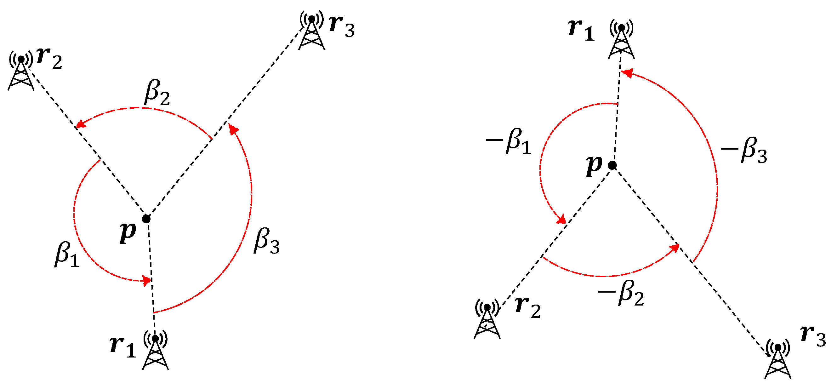
The sixth-order even polynomials in (17) have three pairs of roots each. In the general case where d 1 , d 2 , d 3 are different, A i < 0 , B i < 0 , D i > 0 , implying there are two sign changes between consecutive coefficients A i , B i , C i , D i . According to Descartes’ rule of signs [32], the associated polynomial A i z 3 + B i z 2 + C i z + D i , for some variable z, has two positive real roots and one negative real root. The negative root must be real because a cubic polynomial has either one or three real roots. Thus, the sixth-order polynomials in (17) have two positive roots, two negative roots and two imaginary roots each. Among these six roots, we only consider the two positive roots because the imaginary roots are not applicable and the negative roots are simply the negated versions of the positive roots. Figure 2 shows that, if { β 1 * , β 2 * , β 3 * } satisfies (17), so does { β 1 * , β 2 * , β 3 * } . The optimal geometries are symmetric with respect to the value of the objective function, reflecting all the beacons about the vehicle position gives an equivalent optimal geometry.
The sufficient condition for a stationary point to be a maximum is that the associated Hessian matrix should be negative-definite, i.e.,
H H 11 H 12 H 21 H 22 = 2 | Φ | β 1 2 2 | Φ | β 1 β 2 2 | Φ | β 1 β 2 2 | Φ | β 2 2
has only negative eigenvalues. If β 1 , β 2 satisfy the necessary condition, the sufficient condition reduces to two inequalities:
H 11 + H 22 < 0 ,
0 < H 11 H 22 H 12 2 < ( H 11 + H 22 ) 2 4 .
As demonstrated in the supplementary material in Appendix A, the inequalities in (18) are equivalent to
F F + d 2 sin ( β 1 β 2 ) > 0 ,
d 2 d 3 sin ( β 1 β 2 ) sin β 1 + d 1 d 2 sin ( β 1 β 2 ) sin β 2 + d 1 d 3 sin β 1 sin β 2 > 0 ,
( d 1 sin β 2 d 3 sin β 1 ) 2 + 4 d 2 2 sin 2 ( β 1 β 2 ) > 0 ,
where F = d 1 sin β 2 + d 2 sin ( β 1 β 2 ) + d 3 sin β 1 . At this point, we conclude that if β 1 * , β 2 * , β 3 * satisfy (17) and the inequalities (19), they are the solution to the optimization problem (9).
Theorem 1.
The positive roots of the polynomials in (17) that satisfy
X i > 1 , i = 1 , 2
are the solution to the optimization problem (9).
A proof of Theorem 1 is provided in Appendix A. Theorem 1 is readily applicable to the case where two or three of the beacon ranges are equal. If d i = d j , the polynomial A i z 3 + B i z 2 + C i z + D i has either one positive root or two positive roots. In the former case, the only positive root is the optimizing solution, while, in the latter case, the larger positive root is the optimizing solution. If d i = d j = d k = d , the polynomial A i z 3 + B i z 2 + C i z + D i becomes d 4 z 2 ( z 3 ) , implying tan ( β 1 * / 2 ) = tan ( β 2 * / 2 ) = ± 3 , or, equivalently, β 1 * = β 2 * = β 3 * = ± 2 π / 3 .

6. Simulation Results

This section presents simulation results confirming the validity of the proposed analytical method. Two simulation tasks were performed.
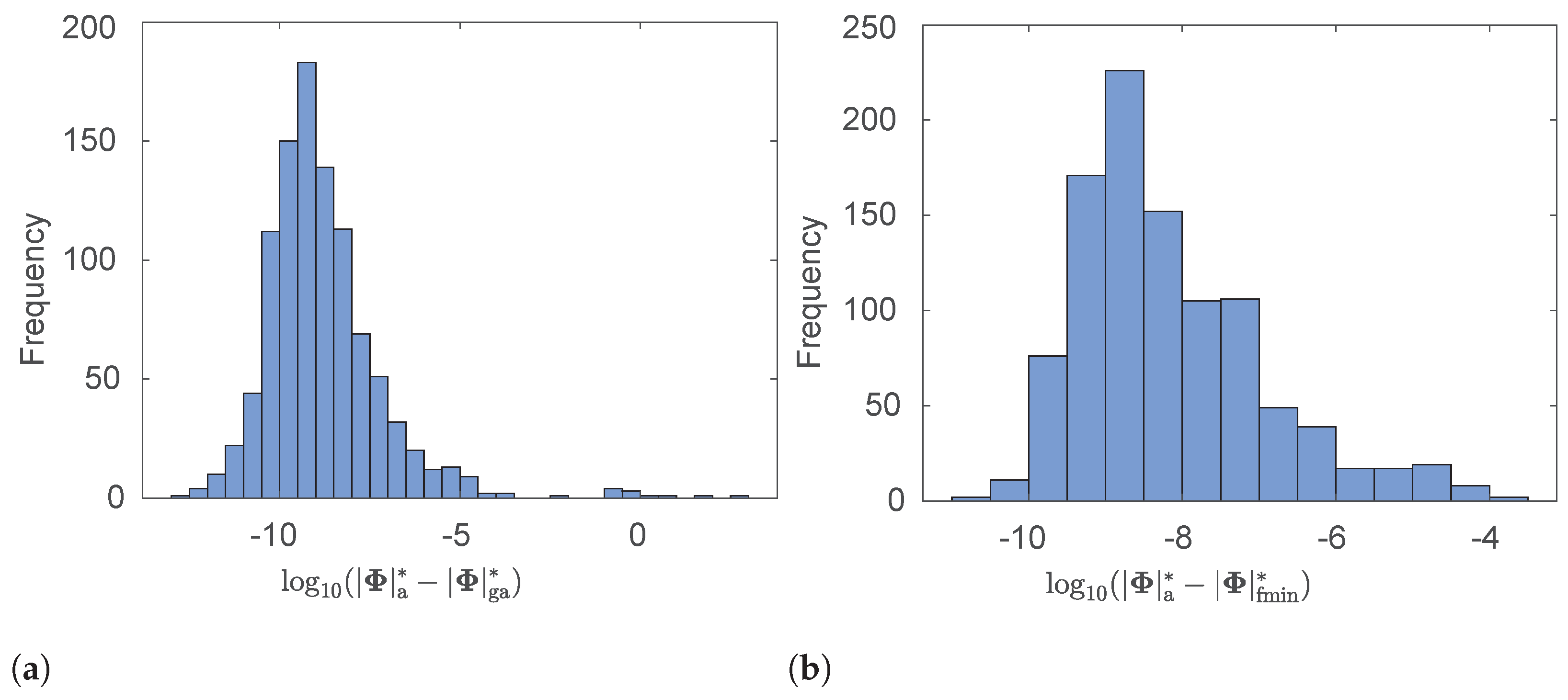
In the first simulation task, the optimal angular separations of the beacons, β 1 * , β 2 * , were calculated using the proposed analytical method for 1000 sets of beacon distances, where each distance is uniformly distributed between 0 and 100 units. For comparison, the optimal angular separations were also computed using (i) the MATLAB function ga, which implements a genetic algorithm; and (ii) the MATLAB function fminsearch, which implements a derivative-free method for finding the minimum of an unconstrained multivariable function. The histograms in Figure 3a,b help us visualize the distributions of differences | Φ | a * | Φ | ga * and | Φ | a * | Φ | fmin * , where | Φ | a * , | Φ | ga * , and | Φ | fmin * are the maximum values of | Φ | calculated using the proposed analytical method, the MATLAB function ga, and the MATLAB function fminsearch, respectively. Our observation that | Φ | a * | Φ | ga * and | Φ | a * | Φ | fmin * are always positive confirms that the maximum value calculated analytically is always larger than the maximum value calculated using either of the other methods.
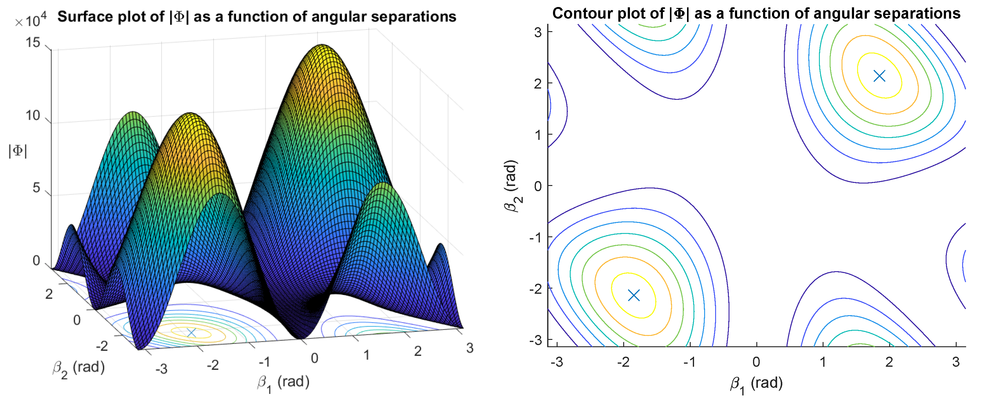
Figure 4 shows a surface plot and a contour plot of the objective function | Φ | as a function of β 1 and β 2 . The objective function has two maxima associated with two sets of angular separations that are negated version of each other (cf. Figure 2). The surface of the objective function is point-symmetric about the origin.
The second simulation task was to evaluate the estimation accuracy of maximum likelihood estimation (MLE) for different beacon geometries.
The maximum likelihood estimates, denoted [ p ^ M L , ϕ ^ M L ] , were obtained by maximizing the log-likelihood function of the noisy bearing measurements ln p ( θ ˜ | p , ϕ ) over the vehicle states ( p , ϕ ) , i.e.,
[ p ^ M L , ϕ ^ M L ] = arg min p R 2 , ϕ R J M L ( p , ϕ ) ,
where J M L ( p , ϕ ) is the maximum likelihood cost function [33]:
J M L ( p , ϕ ) 1 2 e ( p , ϕ ) Σ 1 e ( p , ϕ ) , e ( p , ϕ ) θ ˜ θ ( p , ϕ ) .
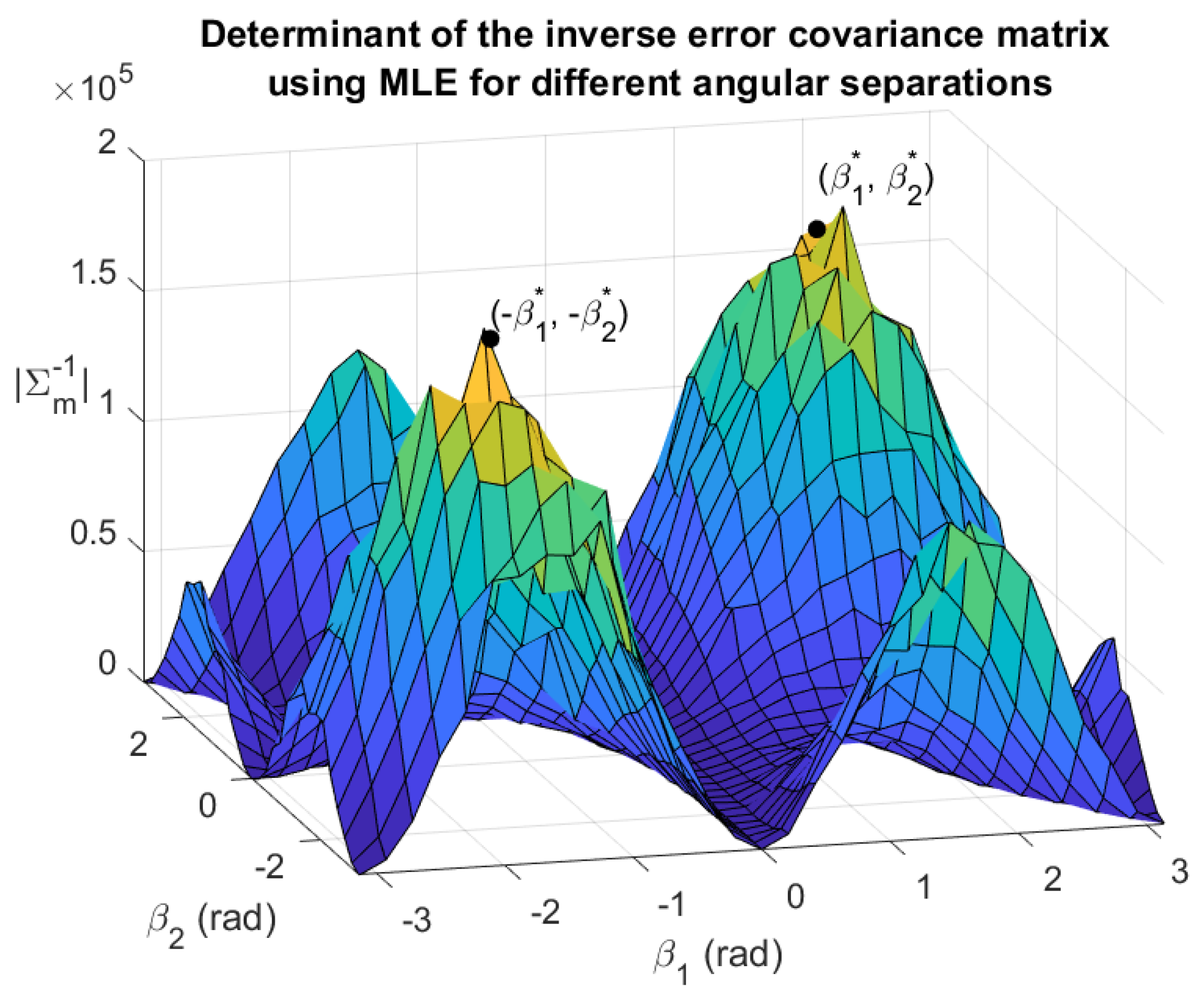
The problem of estimating the vehicle states by minimizing the maximum likelihood cost function in Equation (22) has no closed-form solution, but it can be solved numerically using algorithms such as the Nelder–Mead simplex algorithm, which the MATLAB function fminsearch implements. For this simulation task, the beacon distances associated with Figure 4 were used, and the angular separations of the beacons were varied. As β 1 and β 2 were varied from π to π at a step size of Δ = π 15 radians, 31 × 31 = 961 pairs of ( β 1 , β 2 ) values were generated. For each ( β 1 , β 2 ) value pair, 1000 MLEs were performed to estimate the vehicle states ( p , ϕ ) using AoA measurements corrupted by a zero-mean Gaussian noise with standard deviation σ = 1 ° . The maximum likelihood estimator was initialized at the true vehicle state values to ensure convergence. For each ( β 1 , β 2 ) pair, the determinant of the inverse estimation error covariance matrix | Σ m 1 | was calculated and used to produce Figure 5.
Observe in Figure 5 that the shape of | Σ m 1 | matches that of | Φ | in Figure 4. It is clear that, in practice, the objective function is maximized near the analytically determined optimal beacon placement, as the peaks of the plot in Figure 5 align closely with β 1 * and β 2 * . When the number of MLEs approaches infinity and the grid step size Δ approaches zero, the maxima of | Σ m 1 | are expected to overlap exactly with the maxima of | Φ | .
One of the limitations of this study is the assumption that the measurement noise variance is constant. The constant–variance assumption is common, although in practice the variance can be range-dependent [23,34,35]. Nevertheless, the proposed method is readily modifiable to take into account an alternative measurement noise model, which will depend on the system or application under consideration.
One of the key differentiators in the optimal geometry for self-localization and location estimation is the relationship between optimal geometries for a given set of beacon distances. For any given optimal geometry of an AoA location estimation problem, other geometries that produce the same D-optimality criterion value can be determined by making a point reflection of any number of beacons about the vehicle position [5]. For the AoA self-localization problem using three beacons, there are only two optimal geometries. The two optimal geometries are related by making a point reflection of all the beacons about the vehicle position. The resulting geometries take the form of two mirror-symmetric triangles (see Figure 2).

7. Conclusions

We have developed a method for optimally placing three beacons to minimize AoA self-localization uncertainty. Theorem 1 can be used to determine the optimal angular separations among three beacons such that the D-optimality criterion is satisfied. We proved that the proposed analytical solution satisfies the necessary and sufficient conditions for optimality. Additionally, our simulation results confirm the optimality of the proposed approach. Two simulation tasks were described. In the first simulation task, the optimal beacon angular separations calculated analytically were compared with the beacon angular separations calculated using two numerical methods. The results show that the value of the determinant of the FIM associated with the analytically obtained beacon angular separations is always larger than the value associated with the numerically obtained beacon angular separations. In the second simulation task, for one set of beacon distances, the value of the determinant of the FIM was computed for 961 sets of beacon angular separations using maximum likelihood estimation. The results show that the value of the determinant of the FIM is maximized at beacon angular separations that are close to the analytical solution.
Our future work is related to optimal path planning for self-localization, i.e., the determination of a vehicle trajectory that minimizes self-localization uncertainty. The task can be performed by controlling the vehicle to achieve the best possible self-localization geometry at discrete time intervals. We will extend the results reported here to the problem of optimal path planning.
Author Contributions

Conceptualization, K.D. and J.M.; methodology, K.D. and J.M.; software, J.M.; validation, J.M. and Y.W.L.; formal analysis, J.M. and Y.W.L.; investigation, J.M.; resources, J.C.; data curation, J.M.; writing—original draft preparation, J.M.; writing—review and editing, Y.W.L., K.D., and J.C.; visualization, J.M.; supervision, J.C., Y.W.L., and K.D.; project administration J.C.; All authors have read and agreed to the published version of the manuscript.

Funding

This research received no external funding.

Institutional Review Board Statement

“Not applicable”.

Informed Consent Statement

“Not applicable”.

Acknowledgments

This work was supported by the Australian Government Research Training Program (RTP).

Conflicts of Interest

The authors declare no conflict of interest.

Appendix A. Proof for Theorem 1

This supplementary material provides a proof of Theorem 1. For the proof, we need to use the fact
sign ( cos β 1 ) = sign ( cos β 2 ) = sign ( cos ( β 1 + β 2 ) ) = sign ( cos ( ( β 1 + β 2 ) ) ) = sign ( cos β 3 ) ,
based on (16). We also need the following lemmas.
Lemma A1.
The equalities
d 1 sin β 2 = d 3 sin β 1 ,
sin ( β 1 β 2 ) = 0 ,
cannot be both true.
Proof. 
From (16), we know d 1 cos β 2 = d 3 cos β 1 . If equality (A2) is true, then
d 1 d 3 sin β 2 cos β 1 = d 1 d 3 sin β 1 cos β 2 sin ( β 2 β 1 ) = sin ( β 1 β 2 ) = 0 .
If the equality above and the equality (A3) are both valid, then β 1 , β 2 can be determined irrespective of the values of d 1 , d 2 , d 3 , which is not true. Therefore, equalities (A2) and (A3) cannot be both true. □
Lemma A2.
If (A1) is true and
sign ( sin β 1 ) = sign ( sin β 2 ) = sign ( sin β 3 ) ,
where β 1 , β 2 have the same sign and β 3 = β 1 β 2 , then
sign ( cos β 1 ) = sign ( cos β 2 ) = sign ( cos β 3 ) = 1 .
Proof. 
Consider the following cases for positive β 1 and β 2 .
Case 1: sign ( cos β 1 ) = sign ( cos β 2 ) = sign ( cos β 3 ) = 1 and sign ( sin β 1 ) = sign ( sin β 2 ) = sign ( sin ( β 3 ) ) = 1 . This implies β 1 , β 2 and β 3 are all in the first quadrant. However, if β 1 and β 2 are in the first quadrant, then β 3 must be in the fourth quadrant, hence this case is invalid.
Case 2: sign ( cos β 1 ) = sign ( cos β 2 ) = sign ( cos β 3 ) = 1 and sign ( sin β 1 ) = sign ( sin β 2 ) = sign ( sin ( β 3 ) ) = 1 . This implies that β 1 , β 2 and β 3 are all in the fourth quadrant. However, if β 1 and β 2 are in the fourth quadrant, then β 3 must be in the first quadrant, hence this case is invalid.
Case 3: sign ( cos β 1 ) = sign ( cos β 2 ) = sign ( cos β 3 ) = 1 and sign ( sin β 1 ) = sign ( sin β 2 ) = sign ( sin ( β 3 ) ) = 1 . This implies β 1 , β 2 and β 3 are all in the second quadrant. Thus, as long as π < β 1 + β 2 < 3 π / 2 , β 3 is in the second quadrant.
Case 4: sign ( cos β 1 ) = sign ( cos β 2 ) = sign ( cos β 3 ) = 1 and sign ( sin β 1 ) = sign ( sin β 2 ) = sign ( sin ( β 3 ) ) = 1 . This implies β 1 , β 2 and β 3 are all in the third quadrant. Thus, as long as 5 π / 2 < β 1 + β 2 < 3 π , β 3 is in the third quadrant.
In conclusion, cases 3 and 4 are valid, but cases 1 and 2 are not, implying (A5). The same reasoning can be applied to arrive at the same conclusion for negative β 1 and β 2 . □
In our article, we showed that (17) captures the necessary condition for β 1 , β 2 to maximize | Φ | , while the sufficient condition is that the Hessian matrix of Φ , namely
H H 11 H 12 H 21 H 22 = 2 | Φ | β 1 2 2 | Φ | β 1 β 2 2 | Φ | β 1 β 2 2 | Φ | β 2 2
has only negative eigenvalues. In other words, the eigenvalues
λ 1 , 2 = H 11 + H 22 ± ( H 11 + H 22 ) 2 4 ( H 11 H 22 H 12 2 ) 2
must be real and negative, implying
H 11 + H 22 < 0 ,
0 < H 11 H 22 H 12 2 < ( H 11 + H 22 ) 2 4 ,
where
H 11 = 2 F d 1 2 d 2 2 d 3 2 d 2 sin ( β 1 β 2 ) d 3 sin β 1 ,
H 12 = H 21 = 2 F d 1 2 d 2 2 d 3 2 d 2 sin ( β 1 β 2 ) ,
H 22 = 2 F d 1 2 d 2 2 d 3 2 d 1 sin β 2 d 2 sin ( β 1 β 2 ) ,
F = d 1 sin β 2 + d 2 sin ( β 1 β 2 ) + d 3 sin β 1 .
Substituting (A7a), (A7c) and (A7d) into (A6a) gives us (A8a), while substituting (A7a)–(A7d) into the left inequality of (A6b) gives us (A8b):
F F + d 2 sin ( β 1 β 2 ) > 0 ,
d 2 d 3 sin ( β 1 β 2 ) sin β 1 + d 1 d 2 sin ( β 1 β 2 ) sin β 2 + d 1 d 3 sin β 1 sin β 2 > 0 ,
( d 1 sin β 2 d 3 sin β 1 ) 2 + 4 d 2 2 sin 2 ( β 1 β 2 ) > 0 .
Inequality (A8c) is obtained by substituting (A7a)–(A7d) into the right inequality of (A6b). Inequalities (A8) represent the sufficient condition for β 1 , β 2 to maximize | Φ | .
Suppose that the pair β 1 * , β 2 * satisfies the necessary condition represented by (17). If β 1 * , β 2 * additionally satisfy (A4), then inequalities (A8a) and (A8b) are also satisfied. Meanwhile, inequality (A8c) is readily satisfied because of Lemma A1. In other words, if β 1 * , β 2 * satisfy (17) and (A4), then β 1 * , β 2 * satisfy the necessary and sufficient conditions for maximizing | Φ | .
We can simplify the condition represented by (A4) by applying Lemma A2 to (A1) and (A4), which tells us that β 1 * , β 2 * satisfy (A5), which further implies for i = 1 , 2 ,
sign ( cos β i ) = 1 sign 1 tan 2 β i 2 1 + tan 2 β i 2 = 1 tan β i 2 = X i > 1 .
The inequality above is exactly (20). At this point, we conclude that (17)–(20) satisfy the necessary and sufficient conditions for β 1 * , β 2 * to maximize | Φ | .

References

  1. Bulusu, N.; Heidemann, J.; Estrin, D. GPS-less low-cost outdoor localization for very small devices. IEEE Pers. Commun. 2000, 7, 28–34. [Google Scholar] [CrossRef] [Green Version]
  2. Loevsky, I.; Shimshoni, I. Reliable and efficient landmark-based localization for mobile robots. Robot. Auton. Syst. 2010, 58, 520–528. [Google Scholar] [CrossRef]
  3. Niculescu, D.; Nath, B. Ad hoc positioning system (APS) using AOA. In Proceedings of the INFOCOM 2003, Twenty-Second Annual Joint Conference of the IEEE Computer and Communications, IEEE Societies, San Francisco, CA, USA, 30 March–3 April 2003; Volume 3, pp. 1734–1743. [Google Scholar]
  4. Bishop, A.N.; Fidan, B.; Anderson, B.D.; Doğançay, K.; Pathirana, P.N. Optimality analysis of sensor-target localization geometries. Automatica 2010, 46, 479–492. [Google Scholar] [CrossRef]
  5. Doğançay, K.; Hmam, H. Optimal angular sensor separation for AOA localization. Signal Process. 2008, 88, 1248–1260. [Google Scholar] [CrossRef]
  6. Shimshoni, I. On mobile robot localization from landmark bearings. IEEE Trans. Robot. Autom. 2002, 18, 971–976. [Google Scholar] [CrossRef]
  7. Doğançay, K. Self-localization from landmark bearings using pseudolinear estimation techniques. IEEE Trans. Aerosp. Electron. Syst. 2014, 50, 2361–2368. [Google Scholar] [CrossRef]
  8. Esteves, J.S.; Carvalho, A.; Couto, C. Generalized geometric triangulation algorithm for mobile robot absolute self-localization. In Proceedings of the ISIE’03, 2003 IEEE International Symposium on Industrial Electronics, Rio de Janeiro, Brazil, 9–11 June 2003; Volume 1, pp. 346–351. [Google Scholar]
  9. Melo, J.; Matos, A. Survey on advances on terrain based navigation for autonomous underwater vehicles. Ocean Eng. 2017, 139, 250–264. [Google Scholar] [CrossRef] [Green Version]
  10. LaPointe, C.E. Virtual Long Baseline (VLBL) Autonomous Underwater Vehicle Navigation Using a Single Transponder. Master’s Thesis, Massachusetts Institute of Technology, Cambridge, MA, USA, 2006. [Google Scholar]
  11. Jourdan, D.B.; Dardari, D.; Win, M.Z. Position error bound for UWB localization in dense cluttered environments. IEEE Trans. Aerosp. Electron. Syst. 2008, 44, 613–628. [Google Scholar] [CrossRef]
  12. Miles, J.; Kamath, G.; Muknahallipatna, S.; Stefanovic, M.; Kubichek, R.F. Optimal trajectory determination of a single moving beacon for efficient localization in a mobile ad-hoc network. Ad Hoc Netw. 2013, 11, 238–256. [Google Scholar] [CrossRef]
  13. Ucinski, D. Optimal sensor location for parameter estimation of distributed processes. Int. J. Control 2000, 73, 1235–1248. [Google Scholar] [CrossRef]
  14. Bishop, A.N.; Fidan, B.; Anderson, B.D.; Pathirana, P.N.; Doğançay, K. Optimality analysis of sensor-target geometries in passive localization: Part 2-Time-of-arrival based localization. In Proceedings of the 2007 3rd IEEE International Conference on Intelligent Sensors, Sensor Networks and Information, Melbourne, Australia, 3–6 December 2007; pp. 13–18. [Google Scholar]
  15. Hammel, S.; Liu, P.; Hilliard, E.; Gong, K. Optimal observer motion for localization with bearing measurements. Comput. Math. Appl. 1989, 18, 171–180. [Google Scholar] [CrossRef] [Green Version]
  16. Oshman, Y.; Davidson, P. Optimization of observer trajectories for bearings-only target localization. IEEE Trans. Aerosp. Electron. Syst. 1999, 35, 892–902. [Google Scholar] [CrossRef]
  17. Passerieux, J.M.; Van Cappel, D. Optimal observer maneuver for bearings-only tracking. IEEE Trans. Aerosp. Electron. Syst. 1998, 34, 777–788. [Google Scholar] [CrossRef]
  18. Zhang, H.; Dufour, F.; Anselmi, J.; Laneuville, D.; Nègre, A. Piecewise optimal trajectories of observer for bearings-only tracking of maneuvering target. In Proceedings of the 2018 IEEE Aerospace Conference, Big Sky, MT, USA, 4–11 March 2018; pp. 1–7. [Google Scholar]
  19. Sabet, M.; Fathi, A.; Daniali, H.M. Optimal design of the own ship maneuver in the bearing-only target motion analysis problem using a heuristically supervised extended Kalman filter. Ocean Eng. 2016, 123, 146–153. [Google Scholar] [CrossRef]
  20. Xu, S.; Doğançay, K.; Hmam, H. Distributed path optimization of multiple UAVs for AOA target localization. In Proceedings of the 2016 IEEE International Conference on Acoustics, Speech and Signal Processing (ICASSP), Shanghai, China, 20–25 March 2016; pp. 3141–3145. [Google Scholar]
  21. Wang, W.; Bai, P.; Zhou, Y.; Liang, X.; Wang, Y. Optimal configuration analysis of AOA localization and optimal heading angles generation method for UAV swarms. IEEE Access 2019, 7, 70117–70129. [Google Scholar] [CrossRef]
  22. Hernandez, M.L. Optimal sensor trajectories in bearings-only tracking. In Proceedings of the Seventh International Conference on Information Fusion, Stockholm, Sweden, 28 June–1 July 2004; Volume 2, pp. 893–900. [Google Scholar]
  23. Doğançay, K. Single-and multi-platform constrained sensor path optimization for angle-of-arrival target tracking. In Proceedings of the 2010 18th European IEEE Signal Processing Conference, Aalborg, Denmark, 23–27 August 2010; pp. 835–839. [Google Scholar]
  24. Roh, H.; Cho, M.H.; Tahk, M.J. Trajectory optimization using Cramér-Rao lower bound for bearings-only target tracking. In Proceedings of the 2018 AIAA Guidance, Navigation, and Control Conference, Grapevine, TX, USA, 9–13 January 2018; p. 1591. [Google Scholar]
  25. Moreno-Salinas, D.; Pascoal, A.; Aranda, J. Sensor networks for optimal target localization with bearings-only measurements in constrained three-dimensional scenarios. Sensors 2013, 13, 10386–10417. [Google Scholar] [CrossRef] [Green Version]
  26. Xu, S.; Doğançay, K. Optimal sensor placement for 3D angle-of-arrival target localization. IEEE Trans. Aerosp. Electron. Syst. 2017, 53, 1196–1211. [Google Scholar] [CrossRef]
  27. Zhao, S.; Chen, B.M.; Lee, T.H. Optimal sensor placement for target localisation and tracking in 2D and 3D. Int. J. Control 2013, 86, 1687–1704. [Google Scholar] [CrossRef]
  28. Ucinski, D. Optimal Measurement Methods for Distributed Parameter System Identification; CRC Press: Boca Raton, FL, USA, 2004. [Google Scholar]
  29. Dette, H. Designing experiments with respect to ‘standardized’optimality criteria. J. R. Stat. Soc. Ser. B (Stat. Methodol.) 1997, 59, 97–110. [Google Scholar] [CrossRef]
  30. Betke, M.; Gurvits, L. Mobile robot localization using landmarks. IEEE Trans. Robot. Autom. 1997, 13, 251–263. [Google Scholar] [CrossRef] [Green Version]
  31. Bernstein, D.S. Matrix Mathematics: Theory, Facts, and Formulas; Princeton University Press: Princeton, NJ, USA, 2009. [Google Scholar]
  32. Wang, X. A simple proof of Descartes’s rule of signs. Am. Math. Mon. 2004, 111, 525. [Google Scholar] [CrossRef]
  33. Doğançay, K. Bias compensation for the bearings-only pseudolinear target track estimator. IEEE Trans. Signal Process. 2006, 54, 59–68. [Google Scholar] [CrossRef]
  34. Yang, P.; Freeman, R.A.; Lynch, K.M. Distributed cooperative active sensing using consensus filters. In Proceedings of the 2007 IEEE International Conference on Robotics and Automation, Roma, Italy, 10–14 April 2007; pp. 405–410. [Google Scholar]
  35. Chung, T.H.; Gupta, V.; Burdick, J.W.; Murray, R.M. On a decentralized active sensing strategy using mobile sensor platforms in a network. In Proceedings of the 2004 43rd IEEE Conference on Decision and Control (CDC) (IEEE Cat. No. 04CH37601), Nassau, Bahamas, 14–17 December 2004; Volume 2, pp. 1914–1919. [Google Scholar]
Figure 1. Beacon geometry for self-localization.
Symmetry 13 00056 g001
Figure 2. Two equivalent optimal beacon geometries.
Symmetry 13 00056 g002
Figure 3. Histograms showing the distribution of the errors between analytically maximizing | Φ | and numerically maximizing | Φ | using (a) the MATLAB function ga or (b) the MATLAB function fminsearch.
Symmetry 13 00056 g003
Figure 4. | Φ | as a function of β 1 and β 2 where ( d 1 , d 2 , d 3 ) = ( 31.9025 , 25.7053 , 62.9409 ) . The maxima ( β 1 * , β 2 * ) = ± ( 1.8463 , 2.1373 ) radians are indicated with ‘×’.
Symmetry 13 00056 g004
Figure 5. The determinant of the inverse estimation covariance | Σ m 1 | plotted as a surface function for a grid of β 1 and β 2 with resolution Δ = π / 15 . ( d 1 , d 2 , d 3 ) = ( 31.9025 , 25.7053 , 62.9409 ) , σ = 1 ° .
Symmetry 13 00056 g005
Publisher’s Note: MDPI stays neutral with regard to jurisdictional claims in published maps and institutional affiliations.