Article

Collision Free Smooth Path for Mobile Robots in Cluttered Environment Using an Economical Clamped Cubic B-Spline

Department of Computer Science, Bahria University Islamabad, Lahore Campus 54600, Pakistan
Symmetry 2020, 12(9), 1567; https://doi.org/10.3390/sym12091567
Submission received: 22 August 2020 / Revised: 15 September 2020 / Accepted: 16 September 2020 / Published: 22 September 2020
(This article belongs to the Section Computer)

Abstract

:
Mobile robots have various applications in agriculture, autonomous cars, industrial automation, planetary exploration, security, and surveillance. The generation of the optimal smooth path is a significant aspect of mobile robotics. An optimal path for a mobile robot is measured by various factors such as path length, path smoothness, collision-free curve, execution time, and the total number of turns. However, most of the planners generate a non-smooth less optimal and linear piecewise path. Post processing smoothing is applied at the cost of increase in path length. Moreover, current research on post-processing path smoothing techniques does not address the issues of post smoothness collision and performance efficiency. This paper presents a path smoothing approach based on clamped cubic B-Spline to resolve the aforementioned issues. The proposed approach has introduced an economical point insertion scheme with automated knot vector generation while eliminating post smoothness collisions with obstacles. It generates C 2 continuous path without any stitching point and passes more closely to the originally planned path. Experiments and comparison with previous approaches have shown that the proposed approach generates better results with reduced path length, and execution time. The test cases used for experiments include a simple structure environment, complex un-structured environment, an environment full of random cluttered narrow obstacles, and a case study of an indoor narrow passage.

1. Introduction

Optimal path planning for mobile robots is an important aspect of motion planning with various applications in industrial robots [1], planetary exploration robots [2,3,4], medical robots [5,6], humanoid robots [7], driver-less cars [3], cleaning robots [8], and Un-manned Aerial Vehicle (UAV) applications [9,10]. The optimal path refers to find a feasible plan with optimized performance according to application specified criteria [10]. This criteria could be based on one or more conditions such as shortest distance, smoothness, low risk, or maximum area coverage considering different applications and constraints. Smoothness of robotic path also affects energy consumption, fuel requirement, and time to follow trajectory. Non-smooth path restricts robot’s motion with constant speed and causes deceleration followed by reorientation at turns. Consequently, a robot requires more energy [11,12] to follow the trajectory due to a lack of smoothness in the planner generated planned path. Trajectory tracking algorithms [13] are used to provide output velocity and steering commands to follow a planned path. These trajectory tracking algorithms require a feasibly continuous path to minimize controller exertion and trajectory tracking error. Curvature discontinuities in the path make controllers unstable and overshoot energy [13]. The situation becomes worse for heavy machinery such as industrial, defense, or agricultural robots. Hence, path smoothness is essential for mobile robots [14,15] in order to consume less energy and prevention from premature aging and damage. Smooth path generation has not only applications in mobile robotics, but also in medical ultra-precision motion systems such as hip and knee implants for smoothness and the accuracy of movement trajectory [16].
Mostly path planners such as Memory Efficient A* (MEA*), Rapidly exploring Random Tree Star-Adjustable Bounds (RRT*-AB) [15,17,18,19] generate linear piecewise path which is not feasible for robots due to lack of smoothness [12,20]. Path smoothing approaches are applied with planners to generate a final smooth path for a robot to follow. Most of the state of the art in path smoothing is established upon Bézier [21,22,23,24] curves. Bézier based techniques [21,22,23,24] have the limitations of maintaining continuity and suitable degree of curve. Recently, B-Spline based approaches are also used [13] to resolve the aforementioned issues. However, these approaches result in post smoothness collision in a complex environment, which leads to the failure of the robot’s movement. Secondly, they generate longer paths with deviation from originally planned paths and they use a large number of control points. Furthermore, the generation of knot vector for the B-Spline curve is not automated [12] and intuitive, which is not ideal for real-time application. We have proposed a clamped cubic B-Spline based path smoothing approach. Cubic B-Spline is a Computer Aided Graphic Design (CAGD) tool, desirable in multiple domains for its flexibility and high order accuracy functions [25]. This paper presents a path smoothing approach based on clamped cubic B-Spline that not only generates a shorter path, but also performs automated collision avoidance for a post smoothing path. The contributions of proposed smoothing approach are as follows:
  • Post smoothing collision checking and curve improvement.
  • Economical control point adjustment technique.
  • Automated knot vector generation according to planned path.
  • Improved execution time and path length.
  • More closer to the originally planned path.
The next section describes preliminaries concepts of path smoothing domain. Section 3 presents related work in the field. Section 4 presents the proposed methodology. Section 5 presents the results discussion, followed by conclusions and future directions.

2. Preliminaries

The smoothness of robot’s path is measured in terms of continuity. The level of continuity is decided by the differential values of the robotic path [26] also referred to as parametric continuity written as C k , and geometric continuity written as G k , where k is the order of continuity [27]. Parametric continuity ensures smoothness of the curve along with its parametrization while geometric continuity is the visual continuity. Continuity of different levels is shown in Figure 1.
Two path segments f ( u ) and g ( u ) in an interval t of [0, 1]; joining at a common point is referred to as C 0 or G 0 continuous [27], and can be defined by Equation (1). A G 1 continuous path defined by Equation (2) matches the first-order differential values at each joining point while sharing a common tangent direction and velocity [26,27]:
f ( 1 ) = g ( 0 ) .
f ^ ´ ( 1 ) = g ^ ´ ( 0 ) .
Similarly, two path segments are C 1 continuous if first derivatives of the two curves are the same [27], also referred to as velocity continuity, and are defined by Equation (3). Similarly, two path segments are C 2 continuous if second order derivatives of the two curves are the same [27], also referred to as acceleration continuity, are defined by Equation (4). C 1 is enough for slow moving robots, whereas, for fast moving robots, C 2 or curvature continuity is required [28]:
f ´ ( 1 ) = g ´ ( 0 ) .
f ´ ´ ( 1 ) = g ´ ´ ( 0 ) .

3. Related Work

Smooth path generation for mobile robots is usually accomplished by either of the two approaches, each having its own advantages and disadvantages. The first approach applies a kinematic constraint model during the path planning phase [12,13,15,19]. However, non-holonomic constraints require the addition of a robot’s orientation to state vector of planner. This phenomenon involves solving differential equations for each step. This additional dimension increases complexity of configuration space exploration resulting in a more complicated state transition equation, see Figure 2a. The later approach generates smooth path as a post-processing step, after planner generates linear piecewise path ignoring all kinodynamic constraints, see Figure 2b. This approach is less complex. However, it is computationally expensive due to frequent updates considering real world applications and online planners [13,29]. Recently, Mitsubishi Electric Research Laboratories generated a linear piecewise path for semi-autonomous vehicles [29] using RRT* [24] and later applied post-processing smoothing to generate a G 2 continuous smooth path to meet differential constraints of robotic vehicles.
Parametric curves such as Bézier and Splines have been widely used for post-processing path smoothing approaches [12,19,26]. Yang et al. introduced Bézier based smoothing techniques [21,22,23,24] and generated a G 2 continuous path [21,22]. However, these techniques are dependent upon manual parameters for control points’ selection. Similarly, in Spline based approaches [23,24], the control point selection mechanism requires manual adjustment of spline parameters, which hinder the practical implementation for mobile robots. These approaches also do not guarantee continuity at stitching points when multiple Bézier curves are stitched together for longer paths. Furthermore, the collision checking mechanism is also not incorporated with these smoothing approaches. Huh et al. [26] introduced a smoothness scheme using spline and polynomial interpolation preserving G 2 continuity. Later, Chang et al. [30] extended their approach with a limited collision avoidance feature. However, path lengths of both approaches are longer than originally planned paths. Moreover, their collision avoidance method is restricted to three points only and is not generalized for longer curved segments of paths. Elbanhawi et al. proposed a B-Spline based smoothing approach [13], which proved to be more robust than aforementioned approaches due to its ability to maintain continuity and order. It also offers a point insertion based strategy to avoid collision; however, it is only effective in a simple structured environment and fails in un-structured, complex, or narrow passage scenarios. It also lacks a post collision curve improvement mechanism and generates longer paths. Two categories of curve generation schemes are prominent in a path smoothing state of art, i.e., interpolation and approximation. Interpolation based schemes [26,30] pass from all the way points of path, generating a longer curve. Approximation based schemes [13,21,22,23,24] interpolate end points and approximate middle points, generating a shorter curve than interpolation. However, approximation based approaches are based on Bézier functions and inherit limitations of Bézier such as weak local control. Both types of approaches tend to generate curves that may deviate from originally planned paths at certain points and may collide with obstacles, as shown in Figure 3. Sun et al. [31] also used RRT Connect and Cubic Spline for motion planning of wheeled robots. Yang et al. [32] used C 3 continuous spline for corner smoothing for six rotational (6R) joints of a robot manipulator. Cubic splines have recently had a lot of success to maintain the smoothness of a robot’s movement [33].

4. Proposed Smoothing Algorithm

The proposed post-processing smoothing approach is integrated with a sampling based path planner RRT*-AB [15]. The proposed approach receives the way points of planner generated collision free path as input. During post-processing smoothing, it applies clamped cubic B-Spline and continuously checks for possible new collisions occurred and improves smooth path by eliminating post smoothing collisions. The proposed smoothing approach applies approximation based strategy using due to its capability of generating shorter paths in comparison to an interpolation based scheme.
The algorithm of the proposed smoothing approach is described in Algorithm 1. The smoothing algorithm receives path way-points P = [ p x , p y ] and degree of curve k. Hence, initially total control points are the same as the way-points of the planned path; see Algorithm 1, step 1. The proposed approach inserts mid-points in initial and final path segments for effective clamping on the path. If a path consists of three way-points as shown in Figure 4a, i.e., n = 5, p = 3 (cubic curve), then the knot vector would be equal to m = 9, with triple initial and final multiplicities [0, 0, 0.5, 1.0, 1.5, 2.0, 2.5, 3.0, 3.0] for clamping at both ends, as shown in Figure 4b.
Algorithm 1: Clamped B-Spline Smoothing Algorithm.
Symmetry 12 01567 i001
A B-Spline curve of degree p for given n control points P 0 , P 1 , P 2 , , P n , defined by Equation (5).
c ( u ) = i = 0 n N i , p ( u ) P i ,
where P i refers to ith control point and N i , p ( u ) is ith B-Spline basis function of degree p curve, and u is the normalized curve length parameter. A knot vector u ^ is generated (see step 2 in Algorithm 1) using the property defined by Equation (6), and u ^ is a knot vector which consists of m number of non-decreasing real numbers such that
m = n + p + 1 .
The curve is defined using the Cox–de Boor algorithm [34]. There are n basis functions for n number of control points with strong local control at that point. These basis functions are calculated using a recursive algorithm. First order basis functions with their respective knot vectors, u ^ i , u ^ i + 1 are defined by
N i , 0 = {   1 u [ u i ^ , u i + 1 ^ )   0 e l s e } .
Higher orders basis functions (from 2 to p) are defined by
N i , p ( u ) = u u i ^ u i + p ^ u i ^ N i , p 1 ( u ) + u i + p + 1 ^ u u i + p + 1 ^ u i + 1 ^ / N i + 1 , p 1 ( u ) .
The generated path after completion of a de Boor process is a C 2 continuous curve as per inherited properties of cubic B-Spline proven in [13,27,35]. Once the initial smooth path S P is generated, it is evaluated for possible collisions with obstacles in the surrounding due to smoothness introduced; see step 4 in Algorithm 1. If collision occurs in the new path, then the next step is to identify path segments facing collision, as shown in step 5.
Once c o l l i s i o n S e g m e n t s are identified, then an iterative process inserts mid-points between control points of corresponding segments to follow a planned path closely while avoiding collision, as shown in Figure 5d; see steps 6–9 in Algorithm 1. The proposed smoothing approach inserts mid-points (i.e., new control points) only in segments facing collision instead of all path segments. This leads to generation of an updated knot vector. Thus, a suitable knot vector u ^ is generated for a clamped cubic B-Spline, see step 11. Smooth path S P is regenerated after insertion of new control points in collision occurring segments, see step 12. The collision evaluation of smooth path and updating of control points continues until the whole path becomes collision free.
B-Splines are recognized for their flexibility and robustness. The order of a B-Spline curve is independent from the number of control points in contrast to Bézier curves. Its basis functions have better local control of segments [27,35] as compared to Bézier curves and splines. Due to this property, a path segment in B-Spline could be modified without disturbing neighboring segments while preserving the shape of remaining curve segments [13,27,35]. The proposed smoothing approach inherits all the nice properties of B-Spline such as strong local control, built-in C 2 continuity, and order independence of control points [13,27,35]. All these properties are desirable for dynamic re-planning during real time practical application.
Figure 5 shows different phases of smooth curve generated by the proposed approach. Figure 5a shows a linear piecewise planned path generated by planner RRT*-AB [15]. An originally planned path acts as a control polygon for the application of B-Spline. Figure 5b shows a collision occurring after applying the simple clamped B-Spline. The proposed smoothing approach identifies segments with collision to insert new control points. Path improvement is performed by insertion of a new control point in the middle of the affected path segment, as shown in Figure 5c. Figure 5d shows regeneration of smooth path after collision elimination.
The process block diagram is shown in Figure 6. The process figure shows that path planner RRT*-AB receives the environment map as input and generates a linear piecewise path. The path smoothing process receives a planner generated path as input and applies clamped cubic B-Spline using Cox–De Boor process. In case of a collision with obstacles after application of a smoothing algorithm, economical point insertion is performed only in the path segment of collision; see highlighted areas, whereas collision free segments remain free of un-necessary new point insertion. This phenomenon not only saves processing time, but also avoids an increase in path length and unnecessary decrease in a path’s smoothness.

5. Results and Discussion

This section presents results of smooth path generation by the proposed smoothing approach. Three different environment map cases are adopted from bench mark datasets [15,36,37] referred to as case 1, case 2, case 3, and a real-time case study referred to as case 4. Figure 7 and Figure 8 show the application of proposed smoothing approach in three different environments along with another B-Spline-based state of the art smoothing approach [13] discussed in Section 3.

5.1. Performance Metrics

The following metrics are used to evaluate the performance of the smoothing algorithms in known environment with different shapes, frequency, and structure of obstacles:
  • Total Path Length: The total length of path (measured in meters) directly affects the total operational time to cover the distance and the total energy consumption of the mobile robot. Therefore, the short length of smooth path is also desirable leading to energy efficiency: 1 grid cell in grid occupancy map = 1 m.
  • Run Time: The Computational time (measured in unit second) s required to compute the solution is a prominent efficiency indicator of the proposed approach.
  • Collision-free smoothness: It is the most crucial metric as a smooth path obtained in minimal computational time with required continuity and short length will be of no use if it is not free from collision. Once the post smoothing process provides a collision free smooth path, it is applicable to follow.

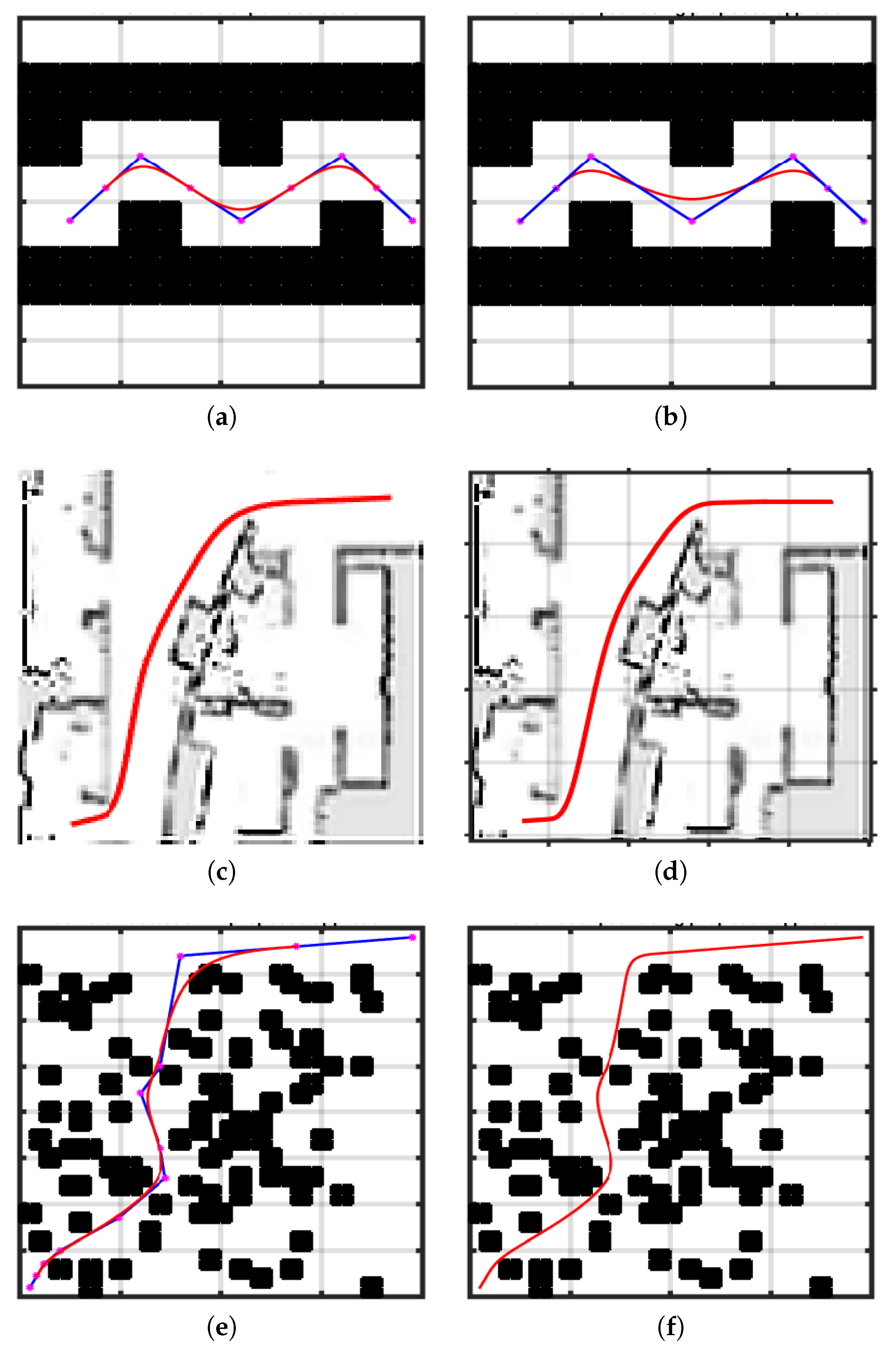
5.2. Experimental Cases

Case 1: Simple and structured environment
Both approaches generate a collision free path successfully for case 1. In this simple environment scenario, there is no post smoothing collision, but a previous approach still inserts mid points and makes the path longer and less smooth, as shown in Figure 7a. However, a path generated by the proposed approach is shorter and consumes less execution time because the proposed approach only inserts points in segments of collision as shown in Figure 7b. Hence, the proposed approach presents a more economical point insertion scheme with respect to execution time and path length.
Case 2: Complex and un-structured environment
It is the scenario of an environment map for indoor unstructured passages and obstacles. In this scenario, post smoothness collision occurs in the top first segment only. The previous approach [13] in Figure 7c is shown. As collision does not occur in every path segment, mid-point insertion in each segment is then merely increasing path length with reduced smoothness. Figure 7d shows evaluation of a smooth curve generated by the proposed smoothing approach presenting shorter and smoother paths than the previous approach.
Case 3: Highly dense obstacles cluttered environment
Case 3 is a map cluttered with dense structured obstacles. Previous methods fail to produce collision free smooth path even with a costly point insertion method for collision avoidance [13] shown in Figure 7d, whereas the proposed approach was successful in generating a collision free smooth path shown in Figure 7f.
Case 4: A case study of an L shape narrow passage
A case study of a second floor office at Bahria University, Lahore Campus is presented. The L shape passage is presented to test the proposed approach. Turtlebot2 was used to run experiments along with a Dell notebook as the Turtlebot notebook. The Turtlebot notebook was set up using Ubuntu 14.04 trusty and the Robot Operating System referred to as the ROS version Indigo along with Turtlebot packages. ROS ASTRA PRO was used as 3D sensors for robots. The configuration settings of robot were performed on an Ubuntu ROS server, i.e., Turtlebot notebook, whereas another computer system was set up as the HOST Node. After network configuration and testing, Turtlebot node was given a Start and End position in an L shape narrow passage environment with linear velocity v as 0.2 m per sec and rotational velocity w 1 deg per sec. Turtlebot completed the passage with collision free smoothness, whereas, when tested using the previous approach, the robot collided with corner of the obstacle. Case 4 of L shape narrow passage is shown in Figure 8.
Smoothing approach presented in [13] uses a mid point insertion technique in every path segment in order to avoid collision. Point insertion for post smoothing collision avoidance is performed at the cost of smoothness, path length, and execution time. Therefore, its final path becomes un-necessarily long. Secondly, a previous approach does not offer an effective post collision curve improvement mechanism because it only generates collision free smooth path for a simple structured environment scenario, whereas it collides with obstacles in a complex unstructured scenario or in an environment cluttered with narrow obstacles, as shown in Figure 7a,c,e, whereas, the proposed approach uses a mid-point insertion strategy economically and inserts mid-points only in segments where collision occurs after applying smoothness. This phenomenon also keeps a path closer to the originally planned path. Consequently, it also provides a better level of smoothness with a short path length of curve. Another challenge is the automated generation of knot vector for its easy application, which is done manually in the previous method, i.e., it is not automated and intuitive for real-time application.
In case 1, the proposed approach generated more smooth time in less execution time than the previous approach. However, the previous approach is not applicable at all in cases 2 and 3 because it failed to generate a collision free smooth path, which is the basic requirement for robotic path to be practical during real-time application—whereas the proposed approach successfully generated a collision free smooth path for all cases. During experiments, it was observed that collision detection, elimination, and path regeneration take 0.04 s, which is very minimal at the cost of collision elimination. However, this difference of runtime is only visible in cases where the proposed approach has to eliminate post smoothing collisions where other approaches fail and generate a path that is not applicable or functional, as shown in cases 2 and 3. Numerical statistics of all cases are presented in Table 1. A feature comparison of proposed approach and Elbanhawi’s smoothing approach [13] is summarized in Table 2. Moreover, a comparison of the proposed approach with state-of-the-art smoothing approaches is summarized in Table 3.
The proposed smoothing approach generates a C 2 continuous path for suitable cases; however, for scenarios of collision due to narrow or complex scenarios, collision elimination is introduced at the cost of decreased continuity. The benefits of proposed approach are summarized as:
  • Inherited properties of clamped cubic B-Spline such as better local control and guaranteed C 2 continuity [27,35].
  • Degree is independent of number of control points as compared to Bézier based approaches [27,35].
  • Collision checking is performed after smoothness application until all collisions are eliminated.
  • Post collision path improvement.
  • Collision based control point adjustment. Point insertion is avoided in collision free curve segments. New control points are inserted only in segments where collision occurs, and hence offers a need based and efficient point insertion scheme.
  • Automated knot vector generation.
  • Approximation with more close following of the planned path.
  • Obeys convex hull property and lies within a boundary of a planner generated path.
  • No stitching or joining points required, one whole single curve represents the smooth curve for the path.

6. Conclusions and Future Directions

This paper discusses path smoothness criteria to define a feasible path for mobile robots. A CAGD tool, i.e., clamped cubic B-Spline, is used to propose a smoothness approach. A major contribution of the proposed smoothing approach is elimination of post smoothness collisions by using an economical mid point insertion scheme in path segments found in collision. A third important feature of the proposed approach is avoidance from stitching points. Contrary to previous Bézier based approaches, a single B-Spline curve is used to generate the whole path avoiding any stitching point and discontinuity. It inherits all the nice properties of clamped cubic B-Spline and generates a feasible smooth path for mobile robots. Comparative analysis with other state-of-the-art smoothness approaches demonstrates path length and time efficiency of the proposed approach. Future directions are to extend the proposed approach with curvature continuity.

Funding

This research is funded by HEC-Pakistan Startup Research Grant Program (SRGP) under grant number 21-2286, with Bahria University Islamabad, Lahore Campus as Host Institution.

Conflicts of Interest

The author declares no conflict of interest. The funders had no role in the design of the study; in the collection, analyses, or interpretation of data; in the writing of the manuscript, or in the decision to publish the results.

Abbreviations

The following abbreviations are used in this manuscript:
UAVUnmanned Aerial Vehicle
CAGDComputer Aided Graphic Design
RRTRapidly Exploring Random Tree
RRT*Rapidly Exploring Random Tree Star
RRT*-ABRRT*-Adjustable Bounds
MEA*Memory Efficient A*
ROSRobot Operating System

References

  1. Lin, Y.; Wu, D.; Wang, X.; Wang, X.; Gao, S. Lift path planning for a nonholonomic crawler crane. Autom. Constr. 2014, 44, 12–24. [Google Scholar] [CrossRef]
  2. Tompkins, P.; Stentz, A.; Wettergreen, D. Global Path Planning for Mars Rover Exploration. In Proceedings of the 2004 IEEE Aerospace Conference Proceedings (IEEE Cat. No.04TH8720), Big Sky, MT, USA, 6–13 March 2004; Volume 2, pp. 801–815. [Google Scholar]
  3. Kuwata, Y.; Fiore, G.A.; Teo, J.; Frazzoli, E.; How, J.P. Motion Planning for Urban Driving using RRT. In Proceedings of the International Conference on Intelligent Robots and Systems, Nice, France, 22–26 September 2008; pp. 1681–1686. [Google Scholar]
  4. Kuwata, Y.; Elfes, A.; Maimone, M.; Howard, A.; Pivtoraiko, M.; Howard, T.M.; Stoica, A. Path Planning Challenges for Planetary Robots. In Proceedings of the International Conference on Intelligent Robots and Systems, Nice, France, 22–26 September 2008; pp. 22–27. [Google Scholar]
  5. Kong, X.Z.; Duan, X.G.; Wang, Y.G. An Integrated System for Planning, Navigation and Robotic Assistance for Mandible Reconstruction Surgery. Intell. Serv. Robot. 2015, 9, 113–121. [Google Scholar] [CrossRef] [Green Version]
  6. Ahmidi, N.; Hager, G.D.; Ishii, L.; Gallia, G.L.; Ishii, M. Robotic Path Planning for Surgeon Skill Evaluation in Minimally-Invasive Sinus Surgery. In Proceedings of the 15th International Conference on Medical Image Computing and Computer-Assisted Intervention, Nice, France, 1–5 October 2012; pp. 471–478. [Google Scholar]
  7. Suh, J.; Gong, J.; Oh, S. Energy Efficient High Dimensional Motion Planning for Humanoids Using Stochastic Optimization. In Proceedings of the 15th IEEE International Conference on Humanoid Robots, Seoul, Korea, 3–5 November 2015; pp. 564–569. [Google Scholar]
  8. Pham, H.V.; Moore, P.; Truong, D.X. Proposed smooth-STC algorithm for enhanced coverage path planning performance in mobile robot applications. Robotics 2019, 8, 44. [Google Scholar] [CrossRef] [Green Version]
  9. Karaman, S.; Frazzoli, E. Sampling-based Algorithms for Optimal Motion Planning. Int. J. Robot. Res. 2011, 30, 846–894. [Google Scholar] [CrossRef]
  10. LaValle, S.M. Planning Algorithms; Cambridge University Press: Cambridge, UK, 2006. [Google Scholar]
  11. Liu, S.; Sun, D. Minimizing Energy Consumption of Wheeled Mobile Robots via Optimal Motion Planning. IEEE/ASME Trans. Mechatron. 2013, 19, 401–411. [Google Scholar] [CrossRef]
  12. Noreen, I.; Khan, A.; Habib, Z. A review of path smoothness approaches for non-holonomic mobile robots. In Science and Information Conference; Springer: Berlin/Heidelberg, Germany, 2018; pp. 346–358. [Google Scholar]
  13. Elbanhawi, M.; Simic, M.; Jazar, R. Continuous Path Smoothing for Car-Like Robots Using B-Spline Curves. J. Intell. Robot. Syst. 2015, 80, 23–56. [Google Scholar] [CrossRef]
  14. Noreen, I.; Khan, A.; Habib, Z. A Comparison of RRT, RRT* and RRT*-Smart Path Planning Algorithms. Int. J. Comput. Sci. Netw. Secur. 2016, 16, 20–27. [Google Scholar]
  15. Noreen, I.; Khan, A.; Ryu, H.; Doh, N.L.; Habib, Z. Optimal path planning in cluttered environment using RRT*-AB. Intell. Serv. Robot. 2018, 11, 41–52. [Google Scholar] [CrossRef]
  16. Guerra, R.H.; Quiza, R.; Villalonga, A.; Arenas, J.; Castaño, F. Digital twin-based optimization for ultraprecision motion systems with backlash and friction. IEEE Access 2019, 7, 93462–93472. [Google Scholar] [CrossRef]
  17. Noreen, I.; Khan, A.; Habib, Z. Optimal Path Planning using Memory Efficient A*. In Proceedings of the IEEE International Conference on Frontiers of Information Technology, Islamabad, Pakistan, 19–21 December 2016; pp. 1–5. [Google Scholar]
  18. Noreen, I.; Khan, A.; Asghar, K.; Habib, Z. A path-planning performance comparison of RRT*-AB with MEA* in a 2-dimensional environment. Symmetry 2019, 11, 945. [Google Scholar] [CrossRef] [Green Version]
  19. Elbanhawi, M.; Simic, M. Sampling-Based Robot Motion Planning: A Review survey. IEEE Access 2014, 2, 56–77. [Google Scholar] [CrossRef]
  20. Noreen, I.; Khan, A.; Habib, Z. Optimal Path Planning using RRT* Based Approaches: A Survey and Future Directions. Int. J. Adv. Comput. Sci. Appl. (IJACSA) 2016, 7, 97–107. [Google Scholar] [CrossRef] [Green Version]
  21. Yang, K.; Gan, S.K.; Sukkarieh, S. An Efficient Path Planning and Control Algorithm for RUAV’s in Unknown and Cluttered Environments. J. Intell. Robot. Syst. 2010, 57, 101–122. [Google Scholar] [CrossRef]
  22. Yang, K.; Jung, D.; Sukkarieh, S. Continuous curvature path-smoothing algorithm using cubic Bézier spiral curves for non-holonomic robots. Adv. Robot. 2013, 27, 247–258. [Google Scholar] [CrossRef]
  23. Yang, K. An efficient Spline-based RRT path planner for non-holonomic robots in cluttered environments. In Proceedings of the International Conference on Unmanned Aircraft Systems, Atlanta, GA, USA, 28–31 May 2013; pp. 288–297. [Google Scholar]
  24. Yang, K.; Moon, S.; Yoo, S.; Kang, J.; Doh, N.L.; Kim, H.B.; Joo, S. Spline-Based RRT Path Planner for Non-Holonomic Robots. J. Intell. Robot. Syst. 2014, 73, 763–782. [Google Scholar] [CrossRef]
  25. Akram, T.; Abbas, M.; Iqbal, A.; Baleanu, D.; Asad, J.H. Novel Numerical Approach Based on Modified Extended Cubic B-Spline Functions for Solving Non-Linear Time-Fractional Telegraph Equation. Symmetry 2020, 12, 1154. [Google Scholar] [CrossRef]
  26. Huh, Y.; Chang, R. A G2 Continuous Path-smoothing Algorithm Using Modified Quadratic Polynomial Interpolation. Int. J. Adv. Robot. Syst. 2014, 11, 25. [Google Scholar] [CrossRef]
  27. Farin, G. Curves and Surfaces for CAGD a Practical Guide, 5th ed.; Morgan-Kaufman: San Francisco, CA, USA, 2002. [Google Scholar]
  28. Habib, Z.; Sakai, M. Spiral Transition Curve and their applications. Sci. Math. Jpn. 2005, 61, 195–206. [Google Scholar]
  29. Lan, X.; Di Cairano, S. Continuous Curvature Path Planning for Autonomous Vehicle Maneuvers Using RRT*. In Proceedings of the European Control Conference (ECC), Linz, Austria, 15–17 July 2015. [Google Scholar]
  30. Chang, R.; Huh, Y. A Collision-Free G2 Continuous Path-Smoothing Algorithm Using Modified Quadratic Polynomial Interpolation. Int. J. Adv. Robot. Syst. 2014, 11, 194. [Google Scholar] [CrossRef]
  31. Sun, Y.; Zhang, C.; Sun, P.; Liu, C. Safe and Smooth Motion Planning for Mecanum-Wheeled Robot Using Improved RRT and Cubic Spline. Arab. J. Sci. Eng. 2019, 45, 3075–3090. [Google Scholar] [CrossRef]
  32. Yang, J.; Li, D.; Ye, C.; Ding, H. An analytical C3 continuous tool path corner smoothing algorithm for 6R robot manipulator. Robot. Comput.-Integr. Manuf. 2020, 64, 101947. [Google Scholar] [CrossRef]
  33. Lian, J.; Yu, W.; Xiao, K.; Liu, W. Cubic Spline Interpolation-Based Robot Path Planning Using a Chaotic Adaptive Particle Swarm Optimization Algorithm. Math. Probl. Eng. 2020, 2020, 20. [Google Scholar] [CrossRef]
  34. Boor, C.D. On calculating with B-splines. J. Approx. Theory 1972, 6, 50–62. [Google Scholar] [CrossRef] [Green Version]
  35. Richard, B.; John, B.; Brian, B. An Introduction to Splines for Use in Computer Graphics and Geometric Modeling; Morgan Kaufmann: San Mateo, CA, USA, 1987; p. 475. [Google Scholar]
  36. Stachniss Lab Photogrammetry & Rotbics; University of Freiburg, Bonn, Germany, 2016; Intel Research Lab (intel.gfs). Available online: http://www2.informatik.uni-freiburg.de/~stachnis/datasets.html (accessed on 22 September 2020).
  37. Nasir, J.; Islam, F.; Malik, U.; Ayaz, Y.; Hasan, O.; Khan, M.; Saeed, M. RRT*-SMART: A Rapid Convergence Implementation of RRT*. Int. J. Adv. Robot. Syst. 2013, 10, 1–12. [Google Scholar] [CrossRef] [Green Version]
Figure 1. Parametric continuity, from left to right as C 0 , C 1 , C 2 .
Symmetry 12 01567 g001
Figure 2. Smooth path generation. (a) during path planning and (b) post planning.
Symmetry 12 01567 g002
Figure 3. Comparison of approximation and interpolation based smoothness. (a) Interpolated smooth path [30], (b) Approximated smooth path [26].
Symmetry 12 01567 g003
Figure 4. Smooth path generation. (a) five control points, (b) clamp B-Spline.
Symmetry 12 01567 g004
Figure 5. Phases of proposed smoothing approach using unstructured complex environment. (a) Path generation by RRT*-AB, (b) B-Spline application, (c) Post smoothing collision, (d) Mid-point insertion in segment of collision, (e) Final smooth path.
Symmetry 12 01567 g005
Figure 6. Block diagram of process steps.
Symmetry 12 01567 g006
Figure 7. Comparison of experimental results of proposed algorithm with the state-of-the-art spline-based algorithm [13], case 1 structured map, case 2 complex un-structured map, and case 3 dense structure environment. (a) Case 1 Elbanhawi et al. [13], (b) Case 1 Proposed, (c) Case 2 Elbanhawi et al. [13], (d) Case 2 proposed, (e) Case 3 Elbanhawi et al. [13], (f) Case 3 proposed.
Symmetry 12 01567 g007
Figure 8. Turtlebot2 on L shape narrow passage running the algorithms.
Symmetry 12 01567 g008
Table 1. Statistical comparison with state-of-the-art algorithm.
CaseMetricElbanhawi et al. [13]Proposed Approach
Case 1: Simple Structured MapCollision StatusCollision freeCollision free
Path Cost31 m29 m
Run Time0.24 s0.17 s
Case 2: Complex Un-structured MapCollision StatusCollisionCollision free
Path CostNA111 m
Run TimeNA0.22 s
Case 3: Dense Cluttered Un-Structured MapCollision StatusCollisionCollision free
Path CostNA119 m
Run TimeNA0.27 s
Table 2. Feature comparison of the proposed approach with cubic spline-based state of the art [13].
FeaturesElbanhawi et al. [13]Proposed Approach
Collision detection and smooth path regeneration strategyNoYes
Economical point insertionNoYes
Suitable for unstructured complex environmentNoYes
Auto knot vector generationNoYes
Table 3. Comparison of proposed approach with other parametric curve based state of the art.
FeaturesYang et al. [22]Huh et al. [26]Elbanhawi et al. [13]Proposed Approach
Continuity G 2 G 2 C 2 C 2
Degree IndependenceNoNoYesYes
Local ControlNoNoYesYes
Avoiding Stitching DiscontinuityNoNoYesYes
Curvature ManagementNoNoYesNo
Collision CheckingPartiallyNoNoYes
Tested on Unstructured mapNoNoNoYes
Post Smoothness Collision Checking and EliminationPartiallyNoNoYes

