Article

An Improved Analytical Tuning Rule of a Robust PID Controller for Integrating Systems with Time Delay Based on the Multiple Dominant Pole-Placement Method

School of Optical-Electrical and Computer Engineering, University of Shanghai for Science and Technology, No. 516 Jun Gong Road, Shanghai 200093, China
*
Author to whom correspondence should be addressed.
Symmetry 2020, 12(9), 1449; https://doi.org/10.3390/sym12091449
Submission received: 20 August 2020 / Revised: 29 August 2020 / Accepted: 1 September 2020 / Published: 3 September 2020
(This article belongs to the Section Mathematics)

Abstract

:
An improved analytical tuning rule of a Proportional-Integral-Derivative (PID) controller for integrating systems with time delay is proposed using the direct synthesis method and multiple dominant pole-placement approach. Different from the traditional multiple dominant pole-placement method, the desired characteristic equation is obtained by placing the third-order dominant poles at −1/λ and placing the second-order non-dominant poles at −5/λ (λ is the tuning parameter). According to root locus theory, the third-order dominant poles and the second-order non-dominant poles are nearly symmetrically located at the two sides of the fifth-order dominant poles. This makes the third-order dominant poles closer to the imaginary axis than the fifth-order dominant poles, which means that, possibly, better performances can be achieved. Analytical formulas of a PID controller with a lead-lag filter are derived. Simple tuning rules are also given to achieve the desired robustness, which is measured by the maximum sensitivity (Ms) value. The proposed method can achieve better performances and maintain better performances when there exist parameters’ perturbation compared with other methods. Simulations for various integrating processes as well as the nonlinear continuous stirred tank reactor (CSTR) model illustrate the applicability and effectiveness of the proposed method.

1. Introduction

Recently, integrating systems have become a study hot topic in terms of automatic control. These types of systems have at least one pole at the origin, which is regarded as the characterization of the open-loop instability [1]. Integrating systems do not have a self-regulating nature. This implies that bounded inputs may lead to unbounded outputs in time domain. This phenomenon makes controlling such processes a difficult task. The type of integral system depends on the number of poles at the origin and the position of other poles in the denominator of closed-loop transfer function [2]. Generally speaking, the following integral systems can be divided into two types: a pure integral plus time delay system (PIPTD), a double integral plus time delay system (DIPTD), a stable first-order plus integral time delay system (FOPTDI) and an unstable first-order integral time delay system (UFOPTD) [3]. Time delay integrated systems exist in many industrial processes, such as a jacketed continuous stirred tank reactor [4], distillation column level and composition control loop [5], boiler drum [6,7], paper drum dryer drum [8], liquid storage tank and bioreactor [9].
Owing to its robustness and simple structure under various operating conditions, Proportional-Integral-Derivative (PID) control has become the most popular control algorithm for regulating integrating processes and has been widely used in industry applications [1]. PID parameter tuning for different types of integral systems is an active research field in the field of automatic control in recent years. In literature, a variety of methods have been reported to design PID controllers for integrating systems with time delay, such as the Internal Model Control (IMC) method [1,10,11], direct synthesis method [12,13], equating coefficient method (ECM) [14], two degree of freedom (2DOF) control scheme [15,16,17], stability analysis method [18] and optimization method [19,20].
Set-point weighting, set point filters and lead-lag filters are commonly used in closed loop to improve the performance. It is suggested that the set-point weighting be introduced to offset the overshoot caused by the zero in closed-loop servo transfer function [21,22]. Uma S. et al. [23] proposed an improved Smith predictor structure for cascaded integral systems with time delay. The weighted control is used to reduce the overshoot. In references [24,25], an additional lead-lag filter has been introduced to the PID controller to achieve better performance than conventional structure. Lee et al. [26] proposed a modified K-SIMC method for integrating processes with time delay. Set point filters have been introduced to limit the integral time and derivative time of the PID controller for better servo performance. Jin Q.B. and Liu Q. [27] proposed adjusting the rules of the 2DOF PID controller using an enhanced IMC method for PIPTD, DIPTD and FOPTDI systems. The adjustment rule is based on a trade-off between robustness and regulatory performance (measured by the Integral Absolute Error (IAE)) by specifying the required MS (maximum sensitivity). Santosh S. and Chidambaram M. [28] have proposed parallel cascade controllers for unstable FOPTD systems. A proportional (P) controller is designed for the secondary inner loop and a PI controller is designed for the primary outer loop. The parameters of the two controllers are obtained by the mathematical equivalence between the numerator of the closed-loop servo transfer function and the corresponding power of s in the denominator. Shamsuzzoha [29] proposed an analysis method to design PID controllers for various types of integral systems. The controller parameters are obtained by closed-loop step setting experiments. In order to get the PID parameters, a simple correlation is derived.
The pole placement method [30] mainly placed two main complex conjugate poles at the desired position in time domain. By specifying the settlement time, damping coefficient and the ratio of integral time to derivative time, the required position can be obtained. Wang Q.G. et al. [31] proposed an optimal pole assignment method with a conventional PID controller for integrating time delay systems including high-order systems. According to the required closed-loop performance, two main complex conjugate poles are selected and two real equations are derived. The I (integral) and D (derived) terms are solved by proportional gain (Kc). Using root locus or Nyquist diagram, the position of all other non-dominant poles can be studied. For the integral system without time delay, the root locus method is used to calculate the controller parameters, and the Nyquist diagram method is used to integrating system with time delay. M. Viteckova and A. Vitecek [32,33,34] have proposed various multiple dominant pole-placement methods for integrating systems. The analytical tuning rule of the PI/PID controller with a set point filter has been proposed. 2DOF PID tuning rule for integrating plants has been presented. Ch. Anil and R. Padma Sree [35] have given an MDP method with a conventional PID controller with an extra lead-lag filter for integrating time delay systems. To obtain the value of the multiple dominant pole and adjustable parameters of PID controller, simultaneous equations of diN/dsi = 0 (for i = 0, 1, 2, 3, N is the characteristic equation) have been solved by Matlab. The main advantage of this method is that it does not need to approximate the time delay of the process model. The methods of references [36,37] are both based on the direct synthesis (DS) approach. On the basis of comparing the expected characteristic equation with the closed-loop characteristic equation, the PID tuning rules of various forms of time delay integral systems are given in Ch. Anil [37]. The expected characteristic equation consists of five principal poles, which are placed in the same desired position.
Literature review shows that although many PID parameter tuning methods are proposed for integral systems with time delay, there is still scope for improving performance and robustness. Inspired by the method of Anil [37], this paper provides a straightforward analytical adjusting rule of a robust PID controller for integral time delay systems based on the modified multiple dominant pole-placement method. The proposed method is basically a combination of the DS method and the modified MDP method. The characteristic equation of the system composed of the control plant, the PID controller and a lead-lag filter is compared with the expected characteristic equation. The required characteristic equations are derived from the MDP method, which divides all the poles into the third-order dominant poles and the second-order non-dominant poles based on the idea of placing as many closed-loop poles as possible in the controller parameters. By placing the third-order dominant poles at −1/λ and placing the second-order non-dominant poles at −5/λ (λ is the tuning parameter), the desired characteristic equation can be easily obtained. According to the object parameters and setting parameters, the PID parameters of various integral systems are given. Setting rules are given as an analytical expression of Ms and tuning parameter.
The structure of this paper is arranged as follows: Section 2 gives the theoretical explanation and the details of the proposed method for all kinds of integrating systems and the rules for selecting the tuning parameter. In Section 3, the robustness, TV and performance indices are discussed. Section 4 gives the simulation results for a high-order system, a non-linear system and disparate types of integrating processes. Section 5 gives the conclusion.

2. The Proposed Method

2.1. Performance Indices

The maximum value of the sensitivity function amplitude ratio (Ms) is considered as a measurement of the robustness and stability of the proposed PID controller. The sensitivity function of the closed-loop control system for the proposed method is written as:
S ( s ) = 1 1 + G c ( s ) G p ( s )
Generally speaking, the process model uncertainty has a direct impact on the performance of the closed-loop system. The types of uncertainties mentioned here include process gain uncertainty, time constant and time delay uncertainties of the process model. The sensitivity function quantitatively reflects the sensitivity of the closed-loop transfer function to the uncertainty of process model parameters. The larger the value of MS, the more susceptible the controller is to parameter uncertainty. Conversely, the smaller the MS value, the better the stability of the controller to process parameter uncertainty. For the stable system, a range of 1.2 to 2 of Ms indicates good robustness. For integral systems considered as a subset of unstable systems, MS is equal to or greater than 2 for robust control. With regard to the proposed PID controller, Ms can be calculated as:
M s = | 1 1 + G p G c | M A X = | 1 1 + k p ( 1 + P s ) e L s s ( τ s + 1 ) k c ( 1 + 1 τ i s + τ d s ) ( α s + 1 β s + 1 ) | M A X

2.2. Theoretical Statements

The multiple dominant pole placement method is a frequently used tuning method of PID controllers for an integrating process. In general, most authors [30,31,32,33,34] use this method to obtain controller parameters by placing two main complex conjugate poles at desired positions. The dominance of a pole requires that the ratio of the real part of any other pole to the real part of the dominant pole is m (the value varies from 3 to 5), and there is no zero nearby. Therefore, all non- dominant poles are located on the left side of the line s = m a , where a is the real part of the dominant pole. The core problem of pole preserving assignment is to determine PID parameters so that the closed-loop poles are located in the desired region except for the main poles. This method makes it possible to determine adjustable PID parameters without overshoot of step response [37].
The multi-dominant pole placement method proposed in this paper is based on the assumption that the performance requirements of closed-loop control in time domain are transformed into multiple dominant poles and non-dominant poles, and there are no zeros nearby. The distance from the non-dominant poles to the origin is five times the distance from the dominant pole to the origin. Simultaneously, all the poles are real and stable and their values of multiplicity are equal to the number of the adjustable parameters of the designed PID controller.
Ch. Anil [37] has placed fifth-order dominant poles in the same location of −1/λ (λ is the tuning parameter) to constitute the closed-loop transfer function. PID parameters are derived on a constraint condition that Ms equals to 2 or exceeds 2. To satisfy the robustness specification, λ should be selected to reach the desired Ms. If the combination of the dominant pole and the non-dominant pole is used to replace the fifth order main pole, the dominant poles and the non-dominant poles must be neatly symmetrically located on both sides of the fifth order main pole to achieve the same Ms. Therefore, the dominant poles are closer to the origin than the fifth-order dominant.
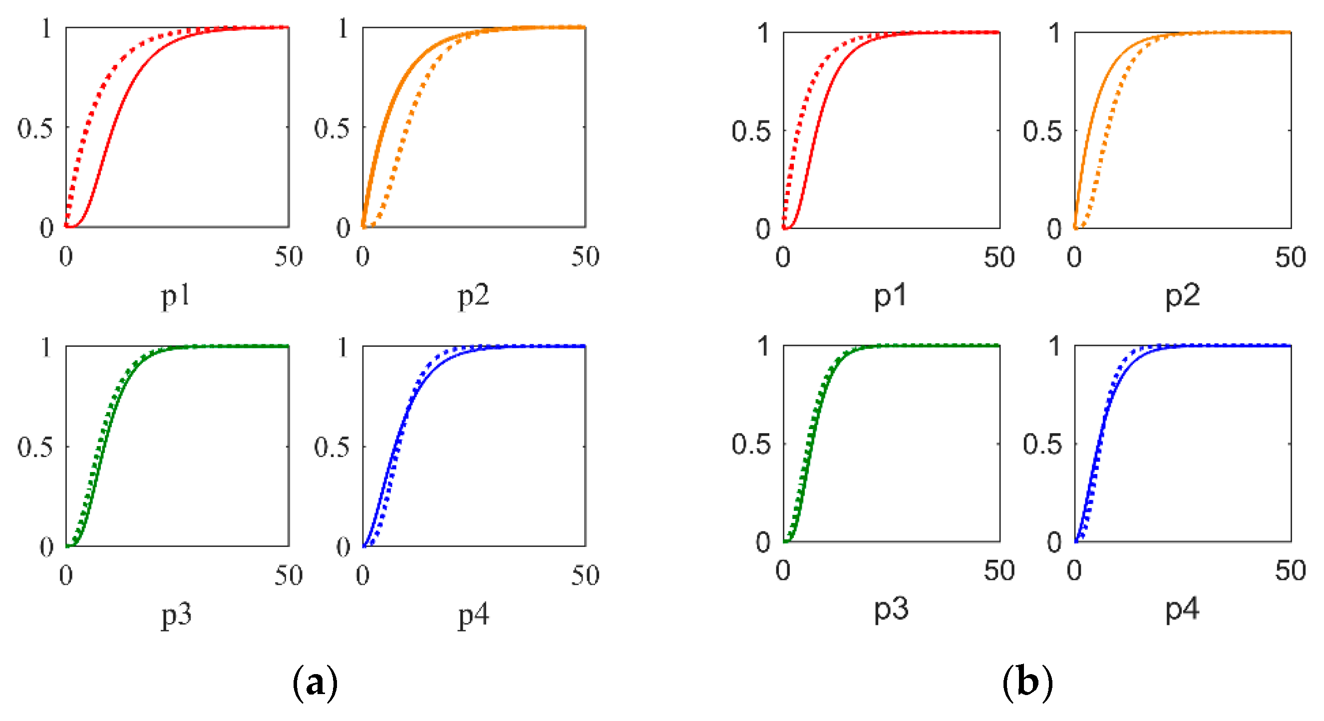
Figure 1a,b give the locations of the 1st-order, 2nd-order, 3rd-order, 4th-order dominant poles with their corresponding non-dominant poles and fifth-order dominant poles for a DIPTD system and an FOPTDI system with Ms = 2 (second-order poles denote two poles located at the same place, 3rd-order poles denote three poles located at the same place, and so forth). In Figure 1, ‘x’ denotes one or more poles at the same location, that is to say, ‘x’ only represents the location of the poles instead of the number. Pi (i = 1, 2, 3, 4, 5) denotes the ith-order dominant poles. It can be seen apparently that the dominant poles and the non-dominant poles are located at both sides of fifth-order dominant poles.
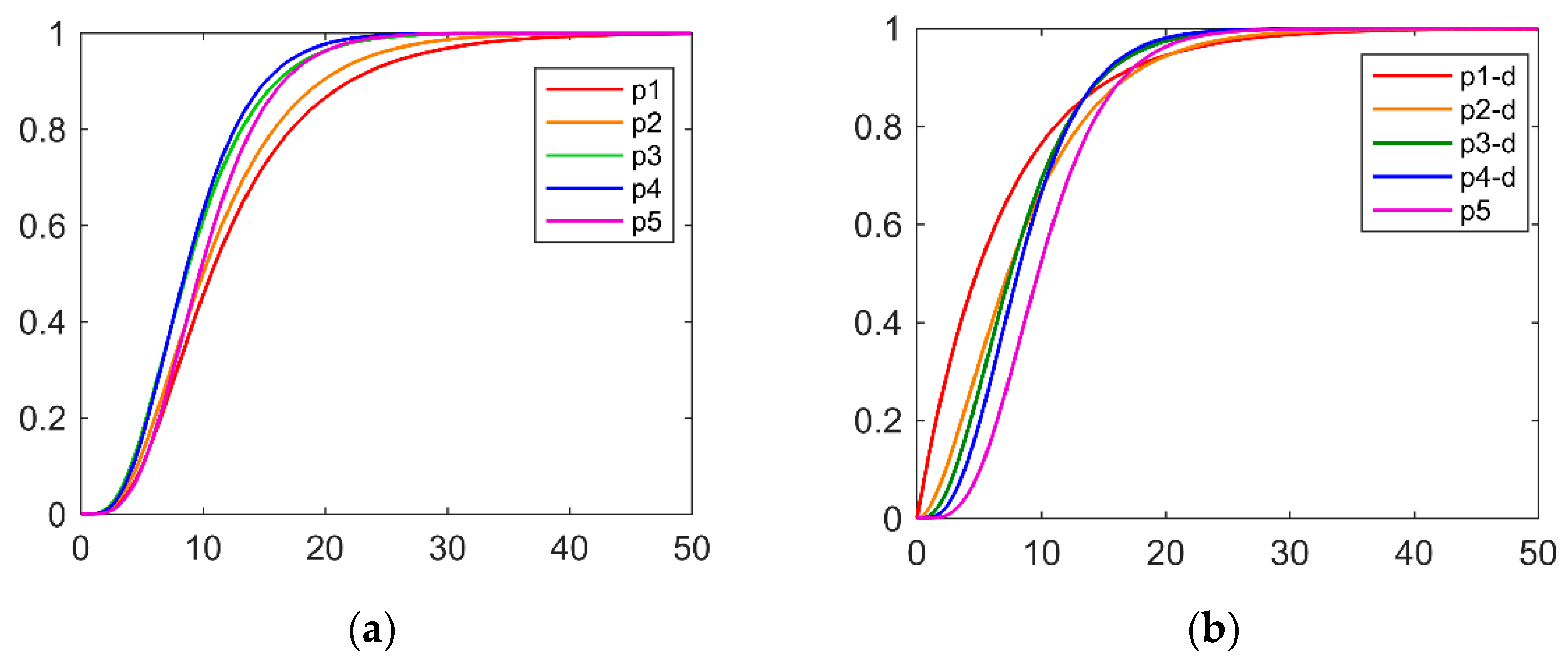
Generally, a smaller distance from poles to the origin results better servo and regulatory performance on the condition that there is only a single pole in a close-loop transfer function or all poles are at the same location. Figure 2 gives the dominance of the 1st-order, 2nd-order, 3rd-order, 4th-order dominant poles for a DIPTD system and an FOPTDI system with Ms = 2. It can be verified that the higher order of the dominant poles yields stronger dominance. In order to achieve better set point tracking performance and robustness, a trade-off between the distance from the multiple dominant poles to the origin and their dominance should be considered.
After numerous simulations, the third-order dominant poles are selected to achieve the best set- point tracking performance and robustness. The correctness and universal applicability of the theory are tested and verified in a large number of simulation experiments. The simulation results are similar to those shown in Figure 3.

2.3. The Process Model

The dynamic process of integral plus time delay process is modeled by the following general transfer function:
G p = k p ( 1 + P s ) e L s s ( τ s + c )
Case1: If τ = 0 ,   c = 1 ,   P = 0 , denote PIPTD systems with the transfer function
G p = k p e L s s
Case2: If τ = 1 ,   c = 0 ,   P = 0 , denote DIPTD systems with the transfer function
G P = k p e L s s 2
Case3: If c = 1 ,   P = 0 , denote stable FOPTDI systems with the transfer function
G P = k P e L s s ( 1 + τ s )
Case4: If c = 1 ,   P > 0   o r   P < 0 , denote stable FOPTDI systems with a positive/negative zero, and the transfer function is expressed as:
G p = k p ( 1 + P s ) e L s s ( τ s + 1 )

2.4. Controller Design

The PID controller with a lead-lag filter is given by Equation (8), where k c is the process gain, τ i is the integral time constant and τ d is the derivative time constant, α and β are viewed as the filter time constant.
G c = k c ( 1 + 1 τ i s + τ d s ) ( α s + 1 ) ( β s + 1 )
The characteristic equation can be calculated by:
N = 1 + G c G p = 0
Substituting Equations (3) and (8) into (9) yields:
N = 1 + k p ( 1 + P s ) e L s s ( τ s + c ) k c ( 1 + 1 τ i s + τ d s ) ( α s + 1 β s + 1 ) = 0
By means of the first order Pade’s approximation for the time delay term, i.e., e L s ( 1 0.5 L s ) / ( 1 + 0.5 L s ) , Equation (10) can be simplified as:
1 + k p k c ( 1 + P s ) ( 1 0.5 L s ) ( τ d τ i s 2 + τ i s + 1 ) ( α s + 1 ) τ i s 2 ( τ s + c ) ( 1 + 0.5 L s ) ( β s + 1 ) = 0
Simplifying and rearranging Equation (11) to extract the common factor of s 5 , s 4 , s 3 , s 2 and s , an equation can be obtained as follows:
( 0.5 τ i τ β L k c k p 0.5 α τ i τ d P L ) s 5 + ( β τ τ i k c k p + 0.5 L c β τ i k c k p + 0.5 τ i τ L k c k p 0.5 τ i τ d P L 0.5 α τ i τ d L + α P τ i τ d 0.5 α τ i P L ) s 4 + ( c β τ i k c k p + 0.5 L c τ i k c k p + τ τ i k c k p + α τ i τ d 0.5 τ d τ i L 0.5 α τ i L   + P τ i τ d 0.5 τ i P L + P α τ i 0.5 P L α ) s 3 ( c τ i k c k p + τ i τ d + α τ i 0.5 τ i L 0.5 α L + P τ i + α P 0.5 P L ) s 2 + ( α + τ i 0.5 L + P ) s + 1 = 0
The expected characteristic equation can be written as:
( λ 5 s + 1 ) 2 ( λ s + 1 ) 3 = 0
Expanding the Equation (13) yields the equation as follows:
λ 5 25 s 5 + 13 25 λ 4 s 4 + 58 25 λ 3 s 3 + 106 25 λ 2 s 2 + 17 5 λ s + 1 = 0  
Equating the corresponding coefficients of s 5 , s 4 , s 3 , s 2 and s in Equation (12) with that of Equation (14), the following five equations can be obtained as:
λ 5 25 = 0.5 β L τ i τ k c k p 0.5 α P L τ i τ d
13 25 λ 4 = β τ τ i k c k p + 0.5 L c β τ i k c k p + 0.5 τ L τ i k c k p 0.5 α L τ i τ d + α P τ i τ d 0.5 P L α τ i
58 25 λ 3 = c β τ i k c k p + 0.5 L c τ i k c k p + τ τ i k c k p + α τ i τ d 0.5 τ i τ d L 0.5 α τ i L + P τ i τ d 0.5 τ i P L + P α τ i 0.5 P L α
106 25 λ 2 = c τ i k c k p + τ i τ d + α τ i 0.5 τ i L   0.5 α L + P τ i + α P 0.5 P L
17 5 λ = τ i + α + P 0.5 L  
It can be deduced logically from the above equation that the adjusting parameter λ is directly related to the controller parameters. By selecting diverse λ for different Ms, simultaneous equations of Equations (15)–(19) can be solved by Matlab.

2.5. Condition for PIPTD System

For PIPTD systems, the lead-lag filter does not show the effect of improving performance. Hence, the conventional PID controller without a lead-lag filter is designed for this system. There are three adjustable PID parameters. The desired characteristic equation is obtained by dealing with the placement of three poles. In order to obtain better performance, the ratio of the distance between the non-dominate pole and the dominate poles to the origin is set to 3. Simultaneously, a combination of second-order dominant poles and a first-order non-dominant pole is chosen to achieve the trade-off between the distance from the multiple dominant poles to the origin and their dominance. The controller parameters can be obtained with the third order characteristic equation.
The characteristic equation for PIPTD processes can be written by:
1 + k p e L s s k c ( 1 + 1 τ i s + τ d s ) = 0
The expected characteristic equation is chosen as:
( λ 3 s + 1 ) ( λ s + 1 ) 2 = 0
By comparing the corresponding coefficients of Equations (20) and (21), PID parameters can be derived from the following three equations.
λ 3 3 = 0.5 τ i L k p k c 0.5 L τ i τ d
5 λ 2 3 = τ i k p k c + τ i τ d 0.5 L τ i
7 λ 3 = τ i 0.5 L

2.6. Selection of the Tuning Parameter and the Tuning Rules

The primary requirement for selecting the tuning parameter λ is to guarantee that all the controller parameters are positive. Furthermore, the adjustment method of λ should make the final controller have good nominal value and robustness (in terms of Ms). After a great deal of simulation experiments and analysis, it was observed that the initial value of λ can be selected as equal to 0.8L, where L is the time delay of the process plant. If good performance is not achieved with this value of λ, then gradually increase the adjustment parameters from this value until a good nominal value and robustness are reached. The range of λ that guarantees good nominal and robustness is L to 3L.
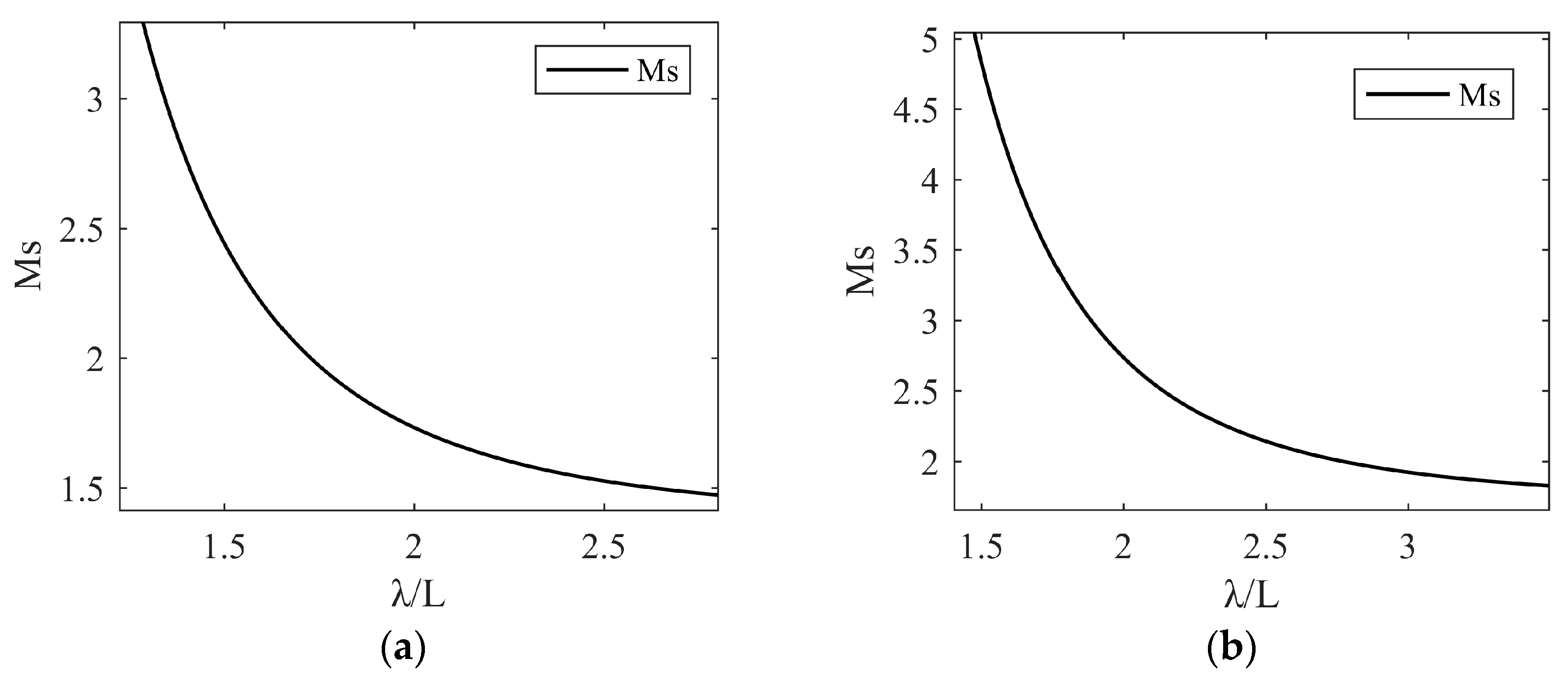
When a specific value of λ is taken into Equations (15)–(19) and Equations (22)–(24), the controller parameters can be obtained with the help of Matlab. Subsequently, Ms can be calculated with these known controller parameters. For different values of λ, obtain the Ms and PID settings, and draw the relationship between Ms and λ. According to this figure, the equations of Ms and λ are fitted by the curve fitting tool in Matlab. Taking the desired Ms into this equation, the tuning parameter of λ can be easily calculated. Finally, all the controller parameters can be obtained. Figure 4 gives the variation of Ms with λ/L for PIPTD systems and DIPTD systems. Table 1 and Table 2 give the tuning rules for PIPTD, DIPTD and FOPTDI (Ms = 2) systems.

3. Robustness, Input Usage and Performance Index

The proposed PID controller is designed not only to ensure the stability of the closed-loop system, but also achieve robustness and performance for servo and regulation problems. In order to illustrate the effectiveness of the proposed analytical method, integral performance index and robustness are adopted in this paper. Moreover, overshoot (OS) is considered as an index of performance evaluation to Section 3.1.

3.1. Integral Performance Index

To measure the performance of the controller, the integral performance index is considered. For single variable systems, there are four frequently encountered error integral rules: the Integral Square Error (ISE), Integral Time Square Error (ITSE), Integral Absolute Error (IAE) and Integral Time Absolute Error (ITAE). In the present work, comparison is carried out in terms of IAE with the PID controllers in other methods. A small value of the indexes mentioned above means fast setpoint tracking and interference suppression. The integral performance index IAE is given by:
I A E = 0 | e | d t

3.2. Total Variation Index

Total Variation (TV) is a performance index to measure the smoothness of the process input or the controller output. It is the sum of the differences between the current process input and previous process input over a period of time which equals to settling time of the systems. A smaller value of TV indicates that the controlled output of the controller is smoother than other methods. When the manipulated variable u(t) of the closed loop system is discretized as a sequence (u1, u2, u3, ..., ui, ...), TV is expressed as:
T V = i = 0 | u i + 1 u i |

4. Simulation and Analysis Studies

In this section, the proposed method are compared with methods reported recently by Ch. Anil and R. Padma Sree (CH) [35,37], Q.B. Jin and Q. Liu (JL) [27], M. Viteckova and A. Vitecek (V.V) [33], M. Ajmeri and A. Ali (A.A) [36], Shamsuzzoha [29] and Lee et al. (Lee) [26]. Various classes of integrating plustime delay models and a non-linear model are considered to illustrate the effectiveness and applicability of the proposed method. The tuning parameter λ is selected to give the same Ms as given by other methods to make sure the performance comparison is carried out for the same robustness level.
Remark 1.
The set point weighting is implemented in the PID controller designed in this paper to improve the servo performance. For fair comparison, the set point weight parameter is set to be ԑ = 0.4 (the same as chosen in Ch. Anil and R. Padma Sree [37]) in the controllers of the proposed method for case 1, case 2, case 3 and case 5. When there is a negative zero (1 + Ps) in the transfer function of process such as case 4 (P is positive), a first order lag filter of 1/(1 + Ps) is added along with the original PID filter (αs + 1)/(βs + 1). This is implemented on the integrating stable first order plus time delay system with a negative zero.
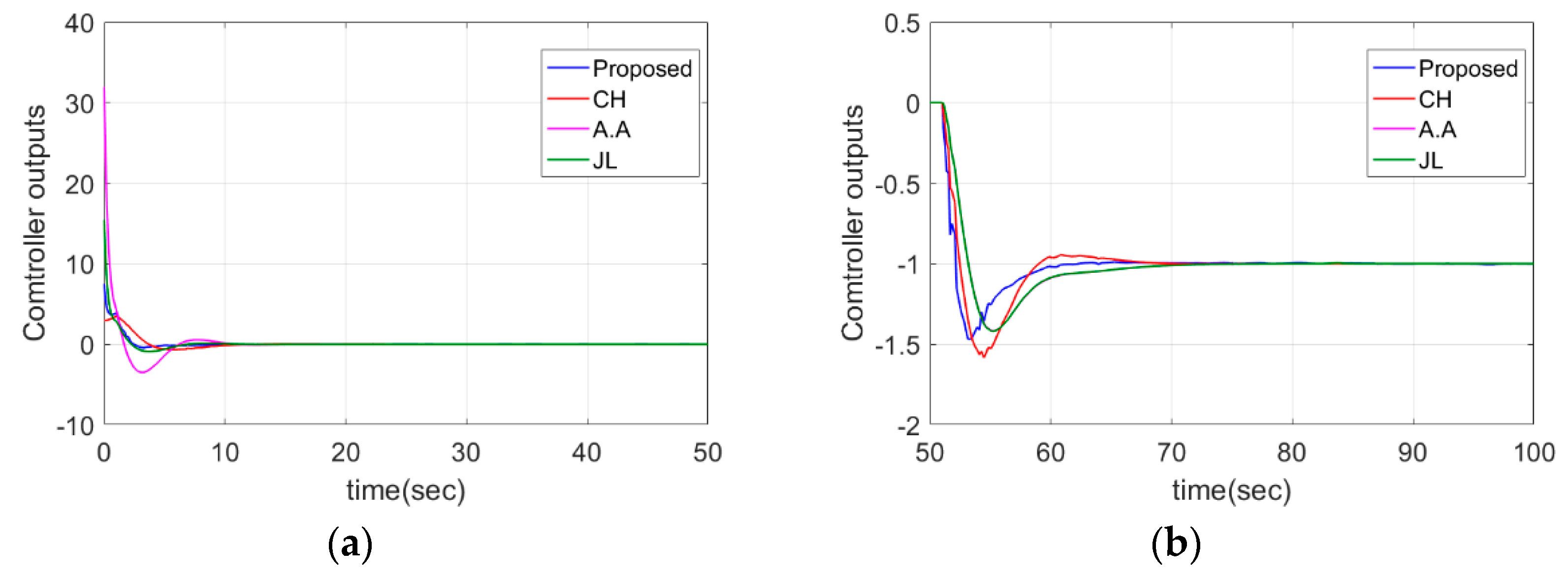
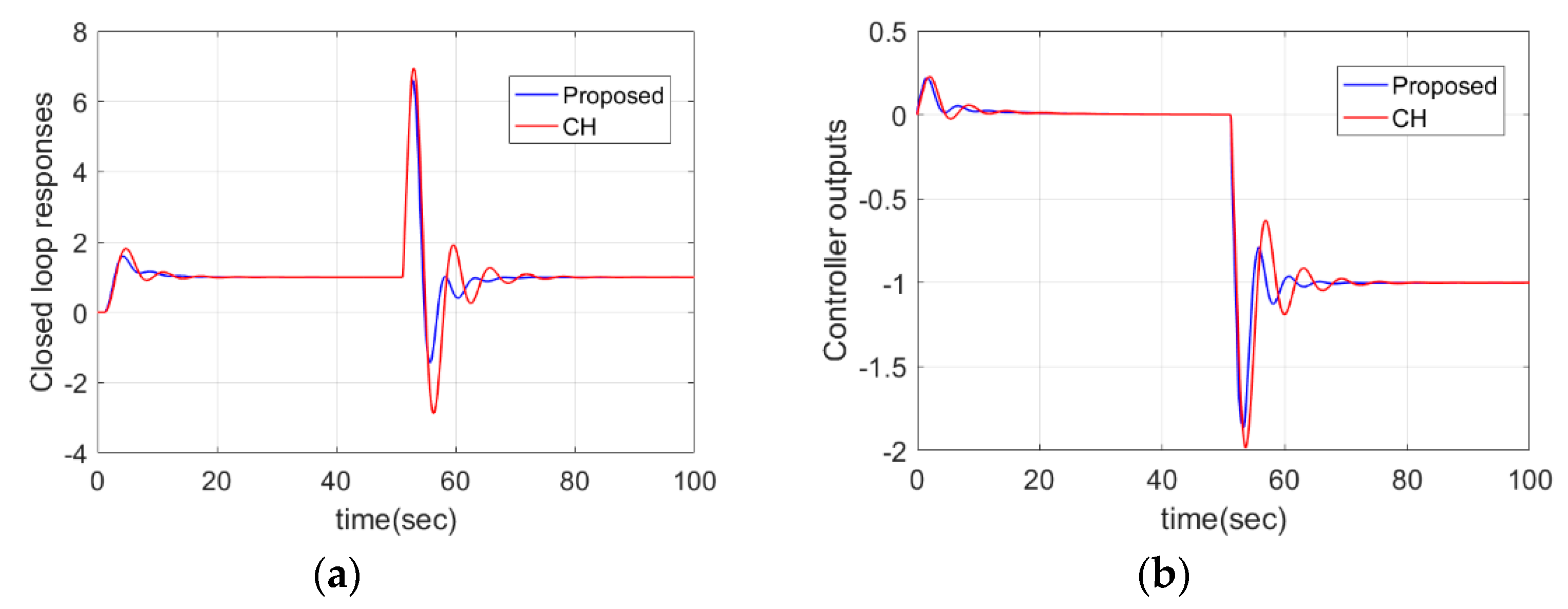
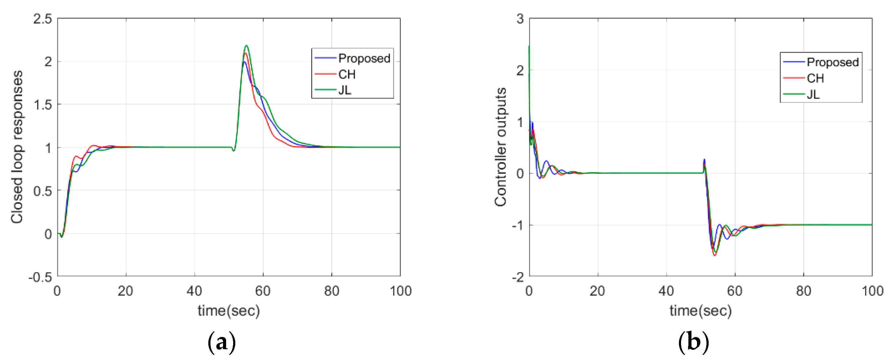
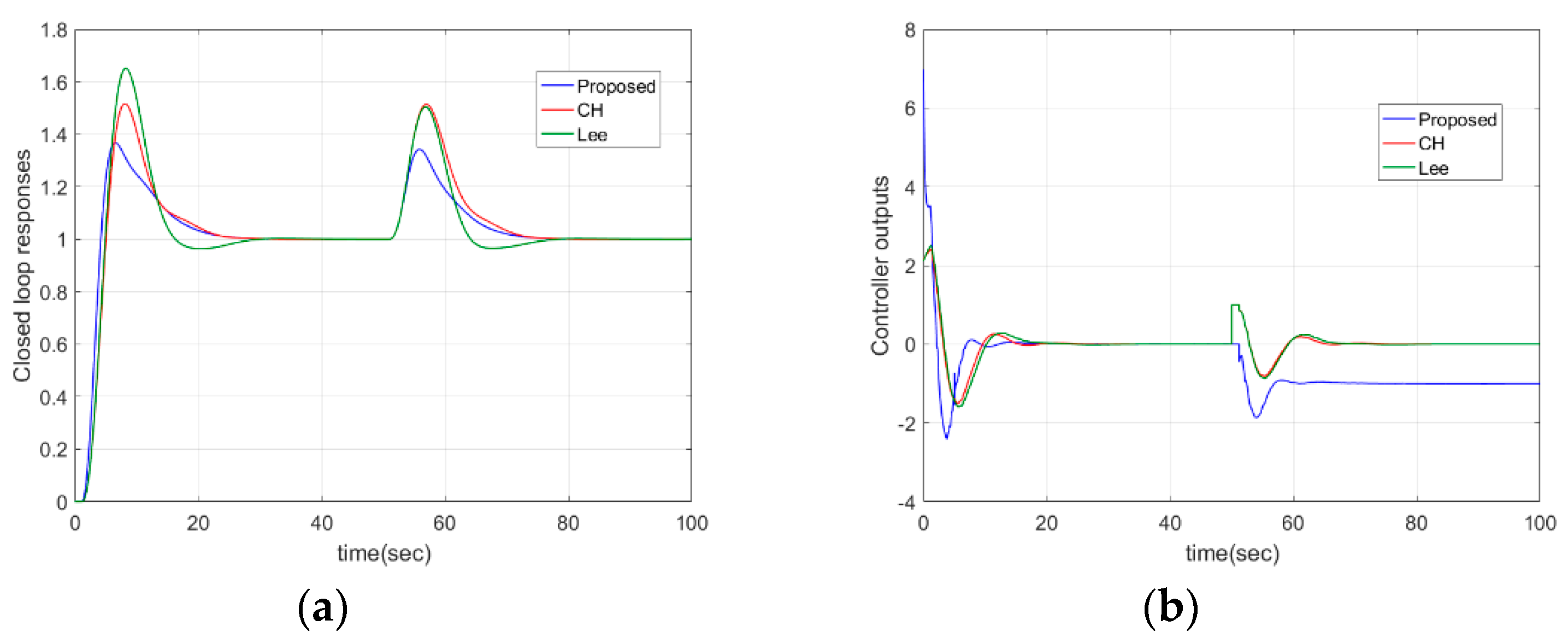
PID settings for 6 cases of various methods are displayed in Table 3. For simulation, step reference and disturbance are considered to illustrate the superiority of the proposed method in the simulation. Table 4 concludes the performance indices of the step response in terms of IAE, TV and OS (maximum overshoot) for all cases. Table 5 concludes the performance indices of step responses considering parameter perturbations. From Table 4, it can be proved that the proposed method almost has the smallest or the second smallest IAE, TV and OS compared with other methods, which implies that the proposed method has almost the best set point performance and the smoothest controller output. From Table 5, it can be seen that the proposed method can maintain the best performances compared with other methods when there exist parameter perturbations. In conclusion, compared with other methods, this method has good set-point tracking and interference suppression performance, and has better robustness.

4.1. PIPTD System

The simulation is conducted for a specific pure integrating time delay process model G p ( s ) = 0.05 e 5 s s . The proposed method is compared with the method of Ch. Anil and R. Padma Sree (CH) [37], M. Viteckova and A. Vitecek (V.V) [33] and M. Ajmeri and A. Ali (A.A) [36]. The value of the tuning parameter λ in the proposed method is adjusted to 8.1 to match the expected Ms given in the above method. The second-order dominant poles are placed at −0.1235 and the third-order non-dominant poles are located at −0.3705.
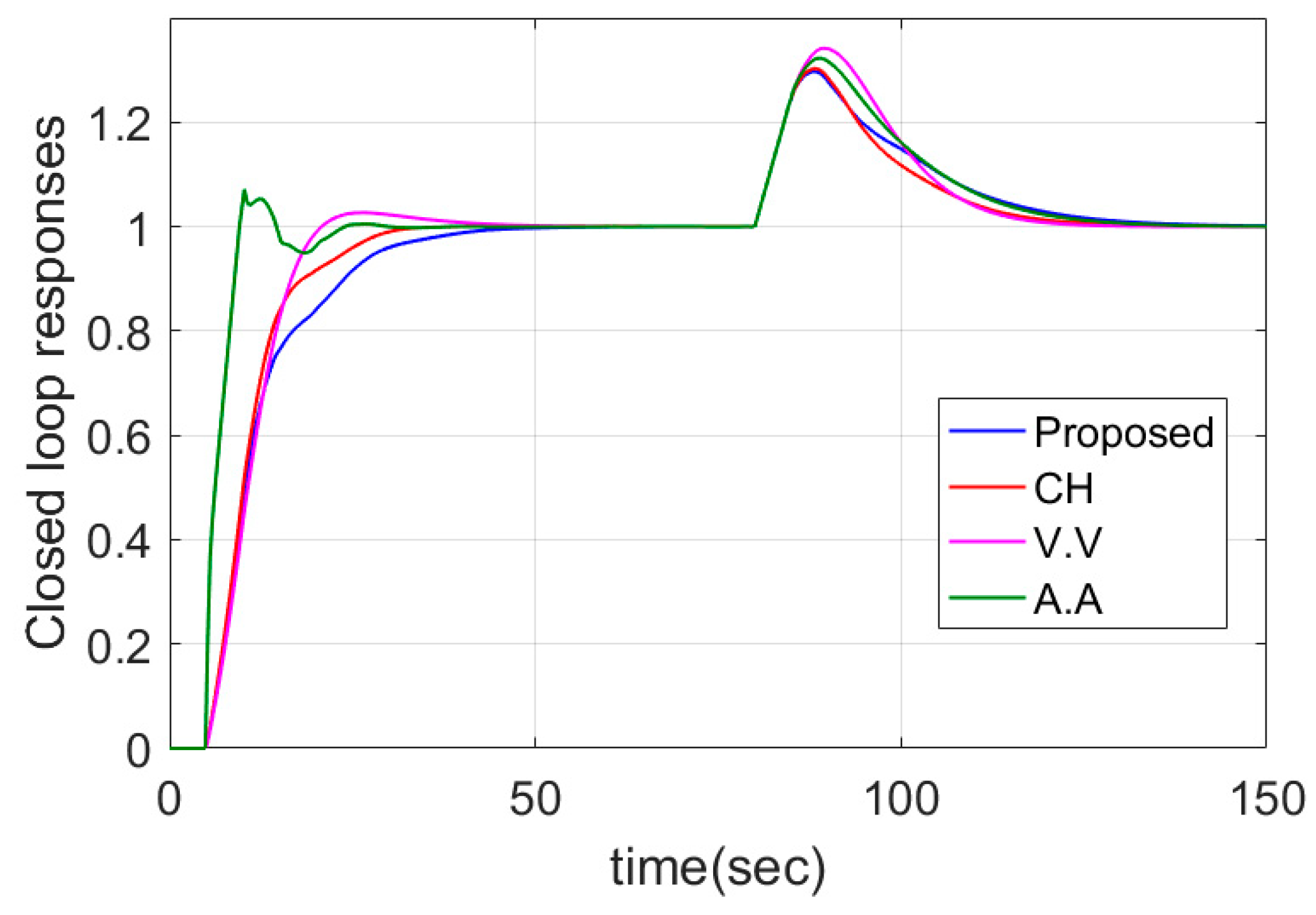
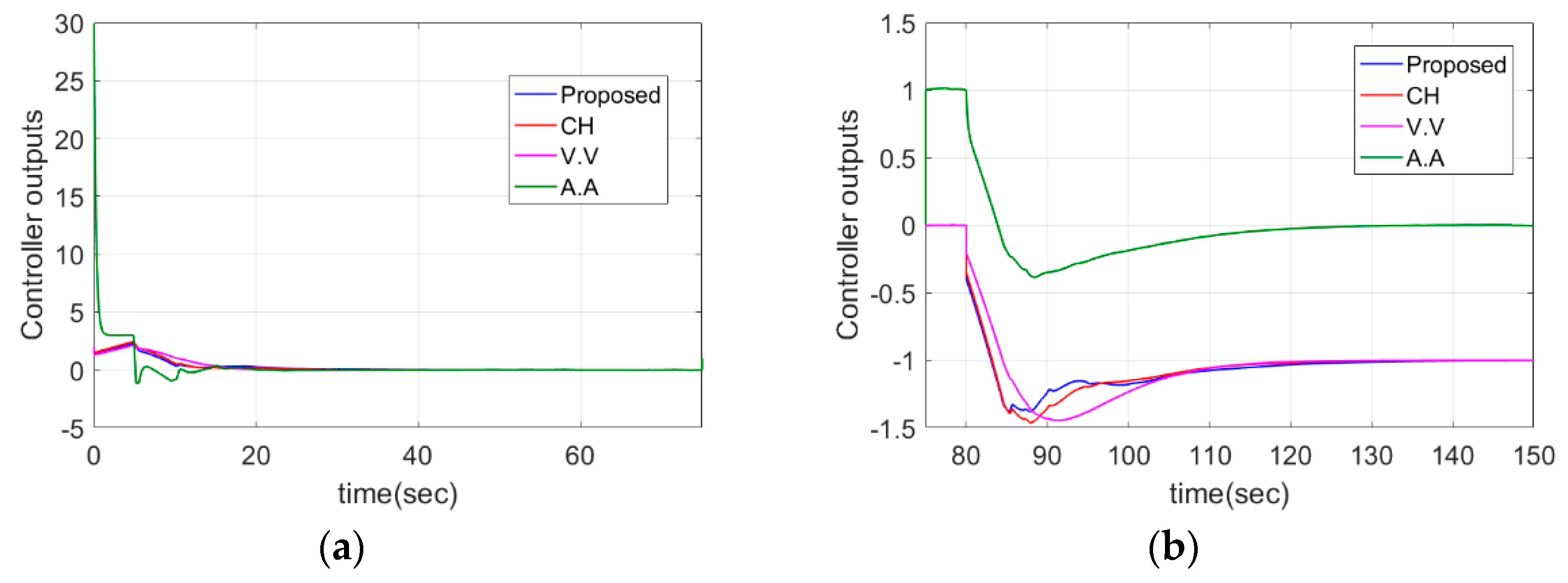
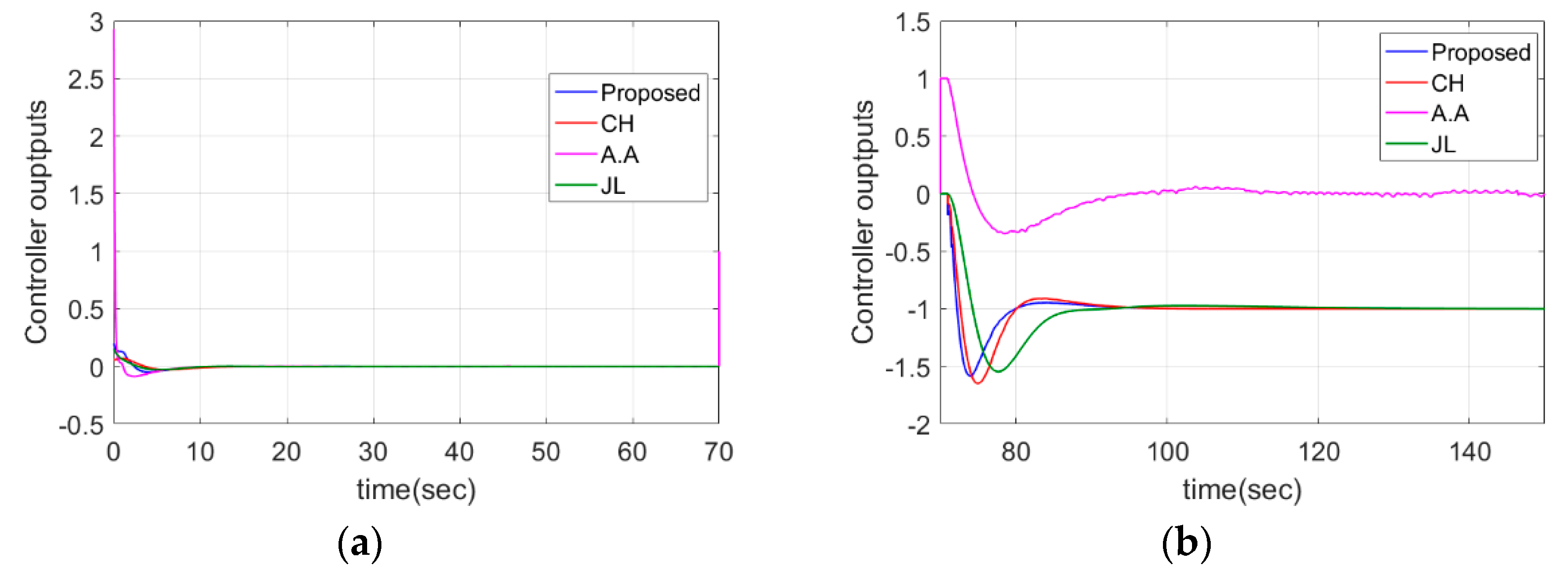
Servo and regulatory responses of various methods are detailed in Figure 5. The controller outputs of different methods are given in Figure 6. From Figure 5 and Figure 6 and Table 3, it can be verified that the controller reported by M. Ajmeri and A. Ali [36] has better servo performance than other controllers owing to the PD controller and the 2-DOF structure, but it has a large overshoot and large value of TV at the same time. The proposed controller has the smallest OS and TV and the IAE is close to the methods designed by Ch. Anil and R. Padma Sree [37] and M. Viteckova and A. Vitecek [33]. For the regulatory problem, the method of Ch. Anil and R. Padma Sree [37] has the smallest IAE and the IAE of the proposed method is close to Ch. Anil and R. Padma Sree [37]. The proposed method has the smallest OS and has the second smallest TV value.
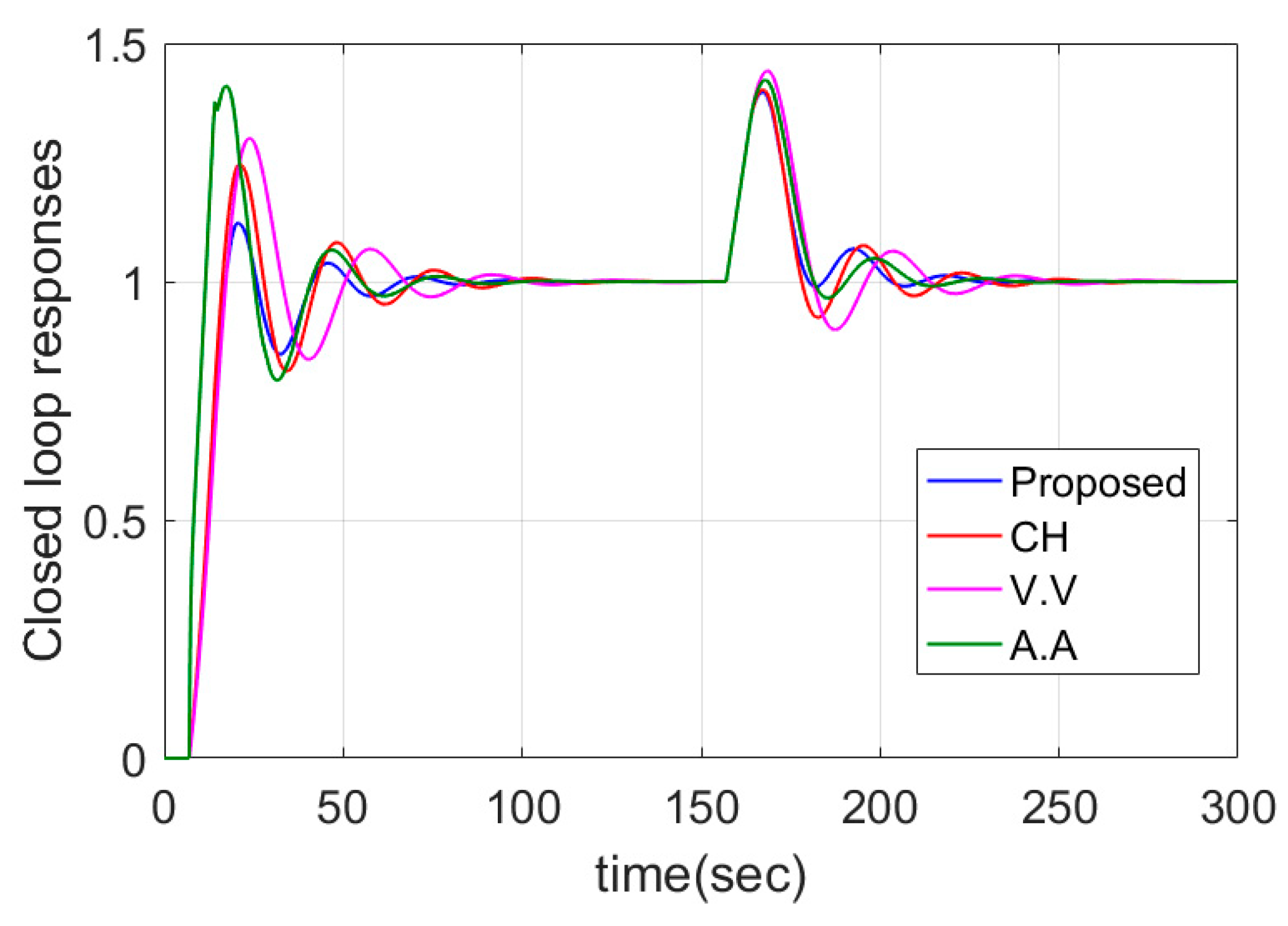
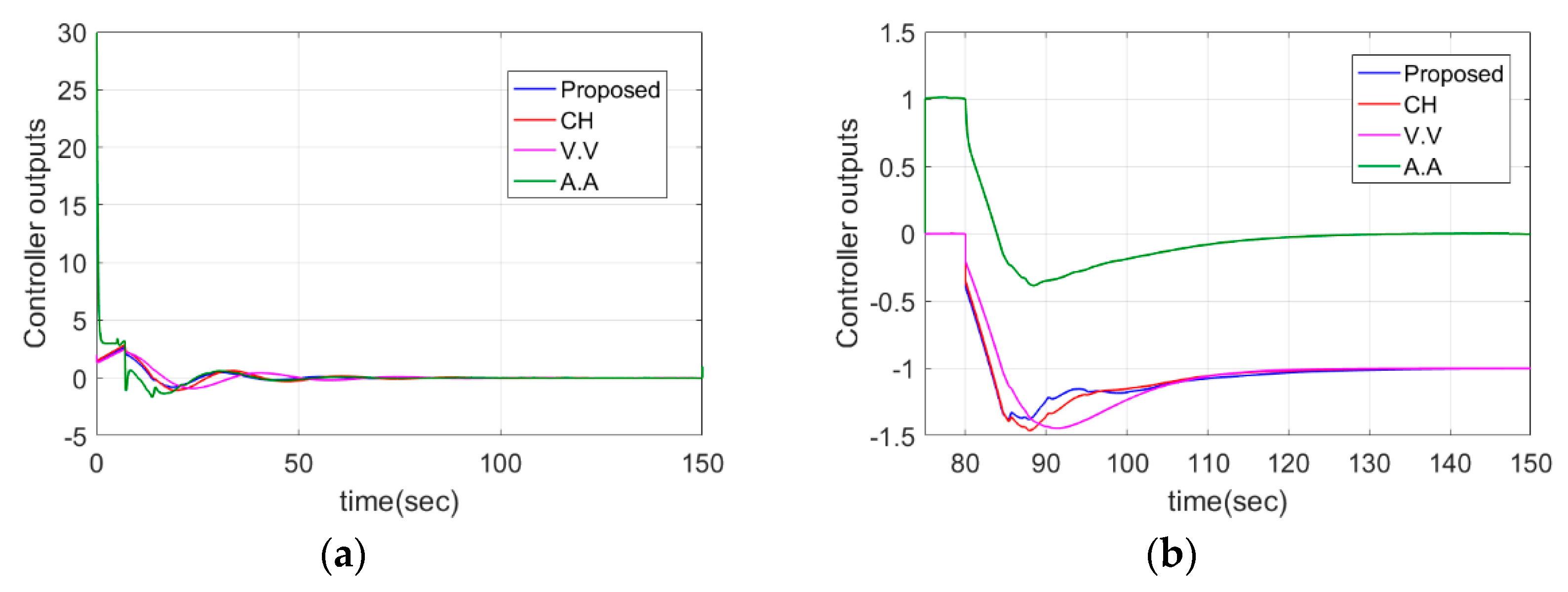
To test the robustness of the proposed method, parameter perturbations are considered. In simulation, 40% perturbation is added to time delay, that is, G r = 0.05 e 7 s s . Figure 7 and Figure 8 give the closed loop responses and controller outputs of different methods. From Figure 7 and Figure 8 and Table 5, it can be seen that the proposed method has the smallest IAE, TV and OS for servo problem. For the regulation problem, the proposed method has the smallest IAE and OS, and the TV is slightly bigger than M. Viteckova and A. Vitecek (V.V) [33].

4.2. DIPTD System

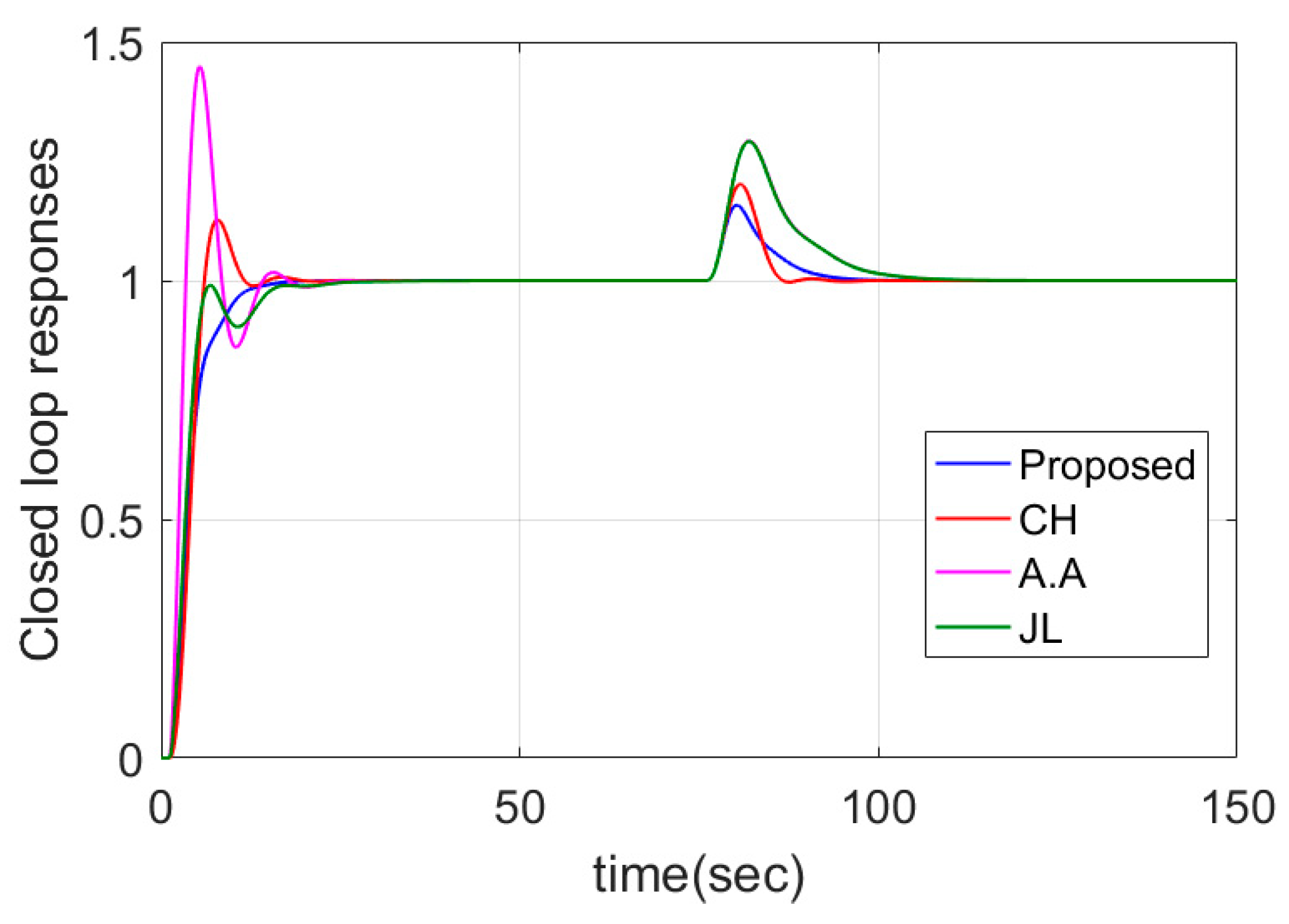
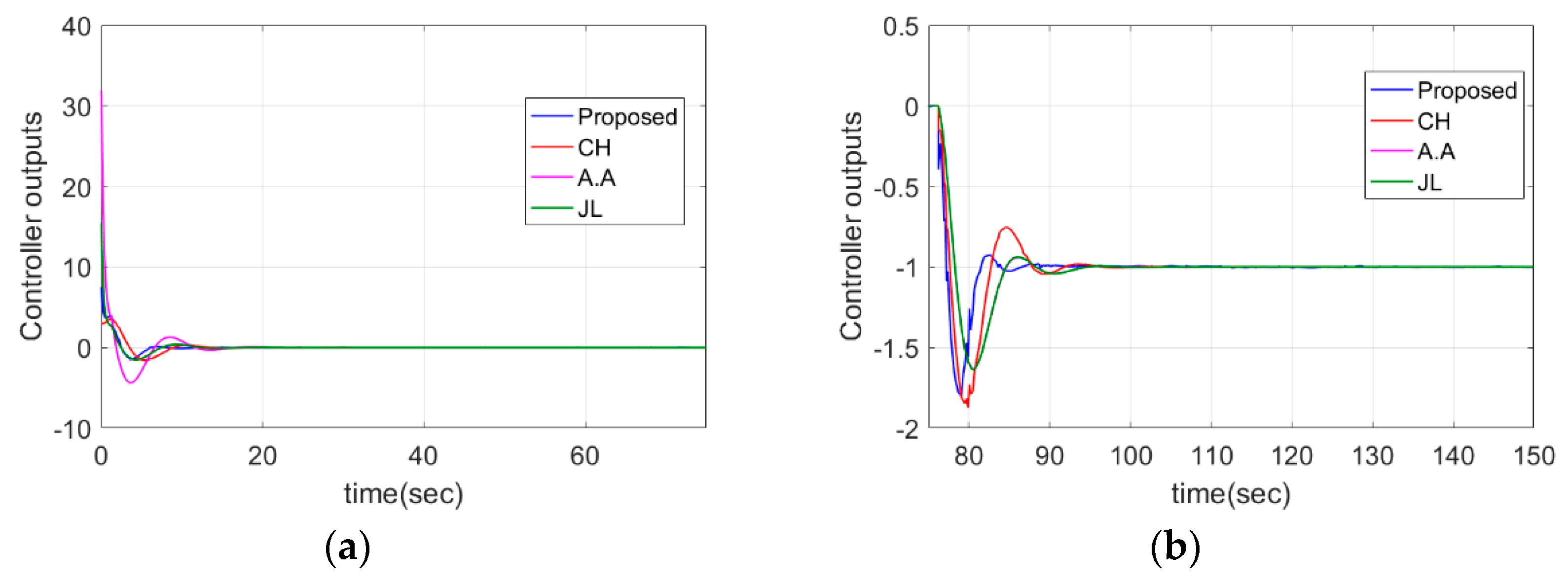
The DIPTD system G p ( s ) = e s s 2 is considered in this section. The proposed method is compared with the methods presented by Ch. Anil and R. Padma Sree (CH) [37], Q.B. Jin and Q. Liu (JL) [27] and M. Ajmeri and A. Ali (A.A) [36]. The tuning parameter λ of the proposed method is adjusted to 2.8232 to meet the desired Ms. The dominant poles are placed at −0.3542 and the non-dominant poles are located at −1.771.
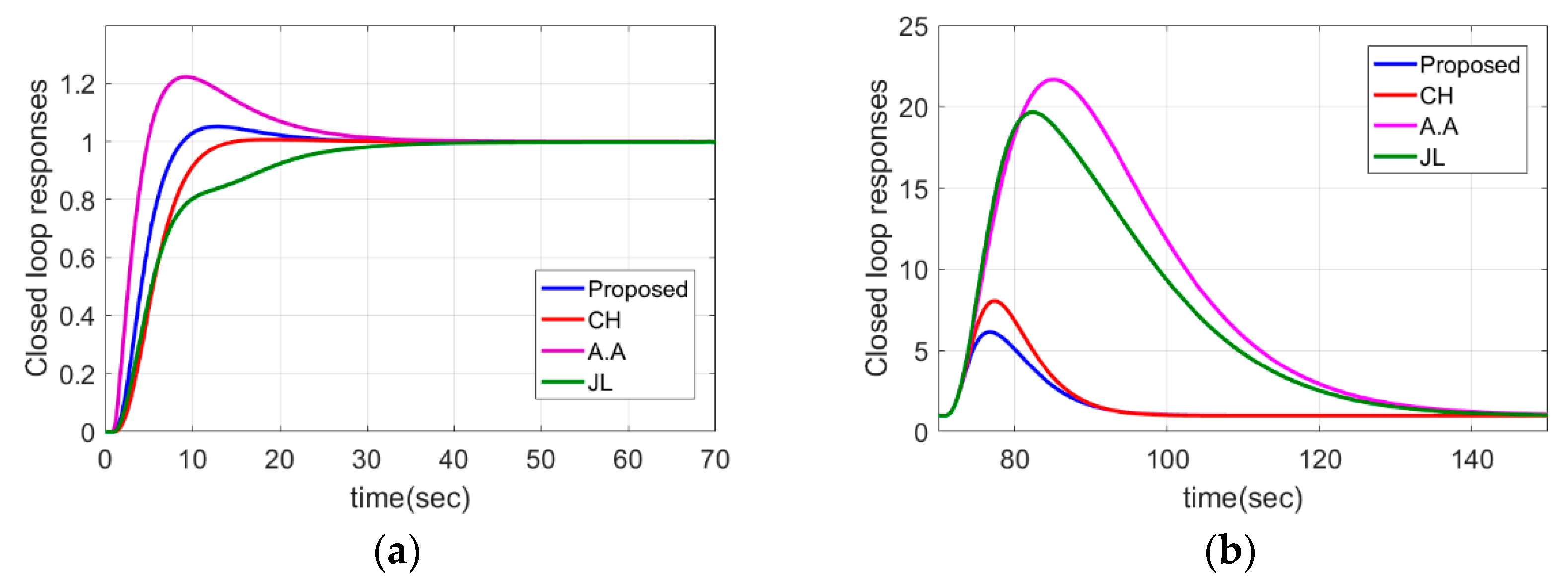
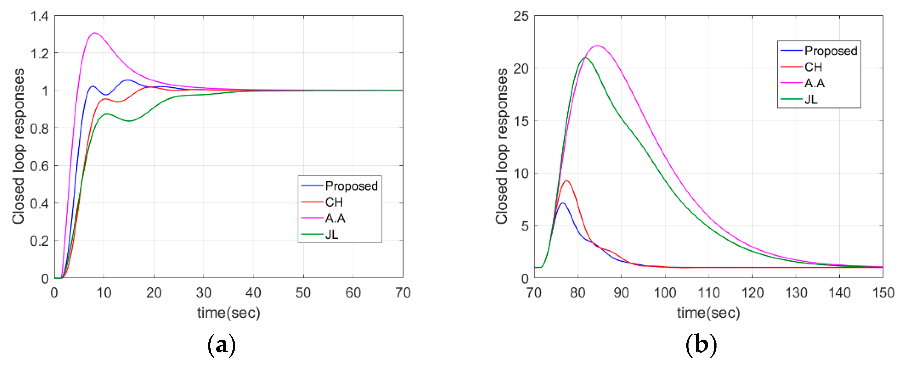
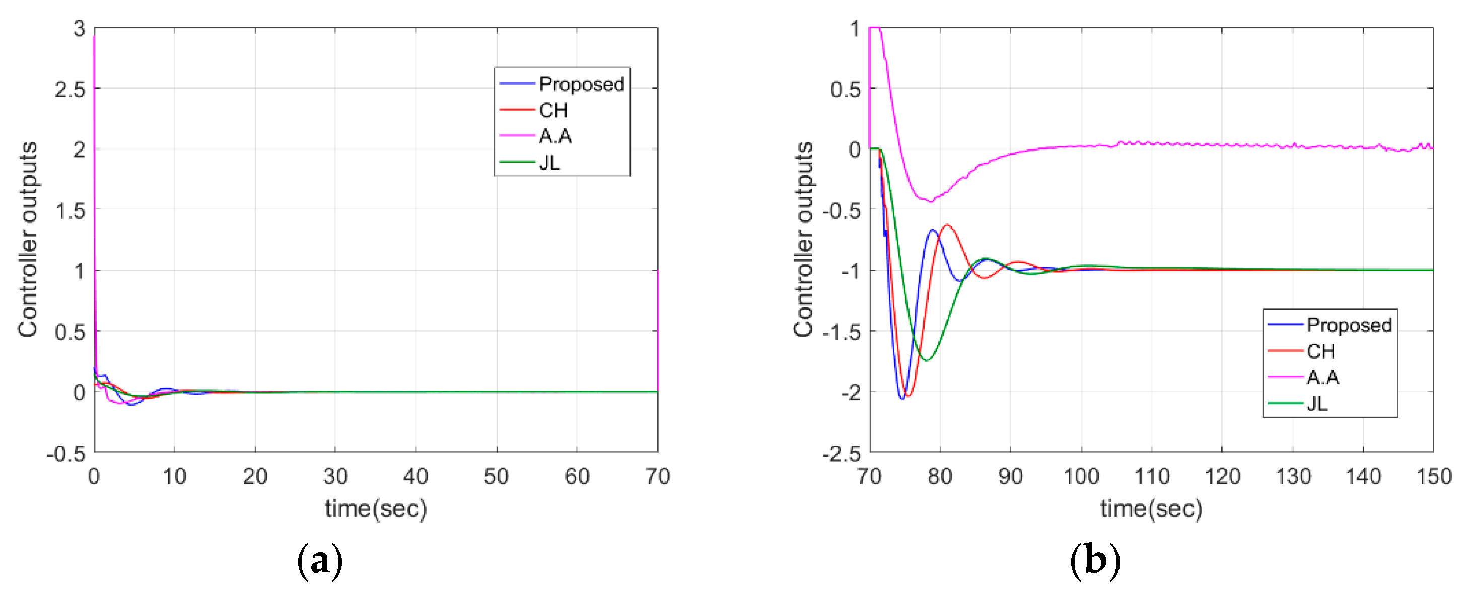
Servo and regulatory step responses of various methods are illustrated in Figure 9a,b. Figure 10 gives the controller outputs. From Figure 9a and Figure 10a and Table 4, it can be seen that proposed method has the second smallest IAE, TV and OS for servo problem. Though the method in M. Ajmeri and A. Ali (A.A) [36] has the smallest IAE value, but the OS and TV are much bigger than the proposed method. For the regulation problem, the proposed method has the smallest IAE and OS.
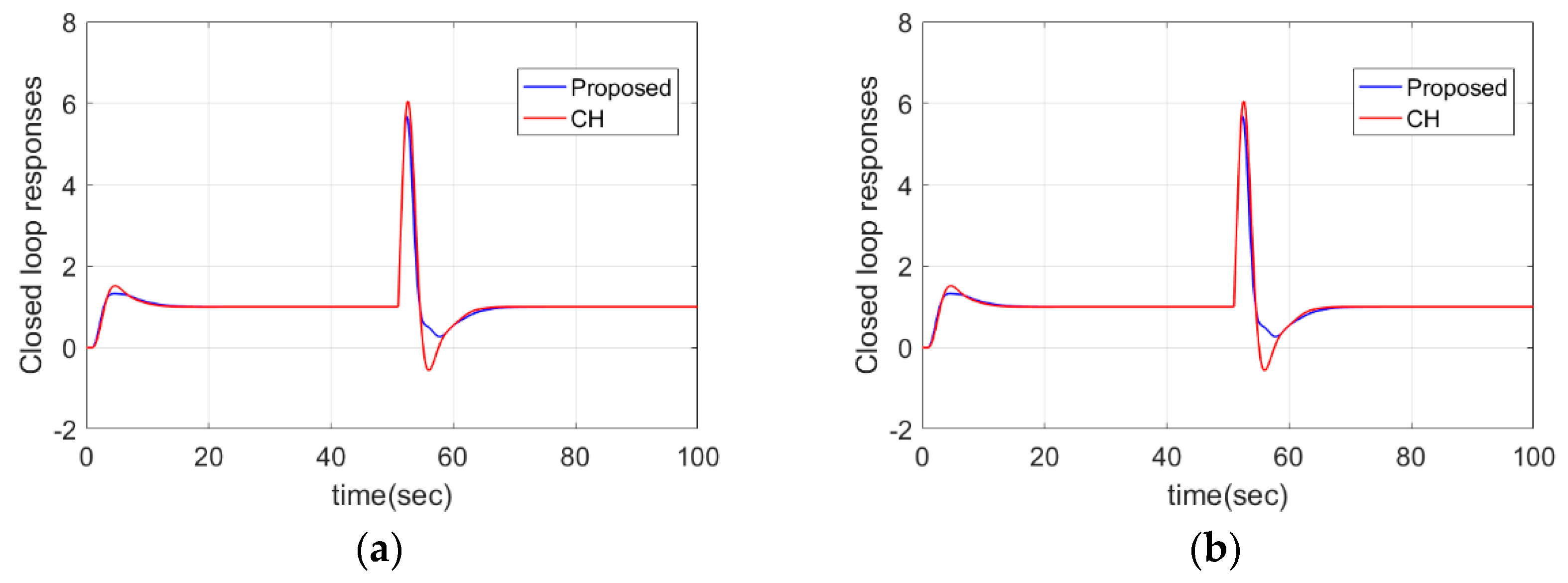
To test the robustness of the proposed method, parameter perturbations are considered. In simulation, 40% perturbation is added to time delay, that is G r = e 1.4 s s 2 . Figure 11 and Figure 12 give the closed loop responses and controller outputs of different methods. From Figure 11 and Figure 12 and Table 5, To solve servo problem, the proposed method has the smallest IAE. The value of TV and OS are close to the methods in Ch. Anil and R. Padma Sree (CH) [37] and M. Viteckova and A. Vitecek (V.V) [33]. For the regulation problem, the proposed method has the smallest IAE and OS.

4.3. Stable FOPTDI System

A stable FOPTDI system G p ( s ) = 0.2 e s s ( 4 s + 1 ) is considered in this part. The proposed method is compared with the methods proposed by Ch. Anil and R. Padma Sree [37], Q.B. Jin and Q. Liu [27] and M. Ajmeri and A. Ali [36]. For the proposed method, the tuning parameter λ is chosen as a value of 2.184 to satisfy the desired Ms. The dominant poles and the non-dominant poles are placed at −0.4579 and −2.2895, respectively.
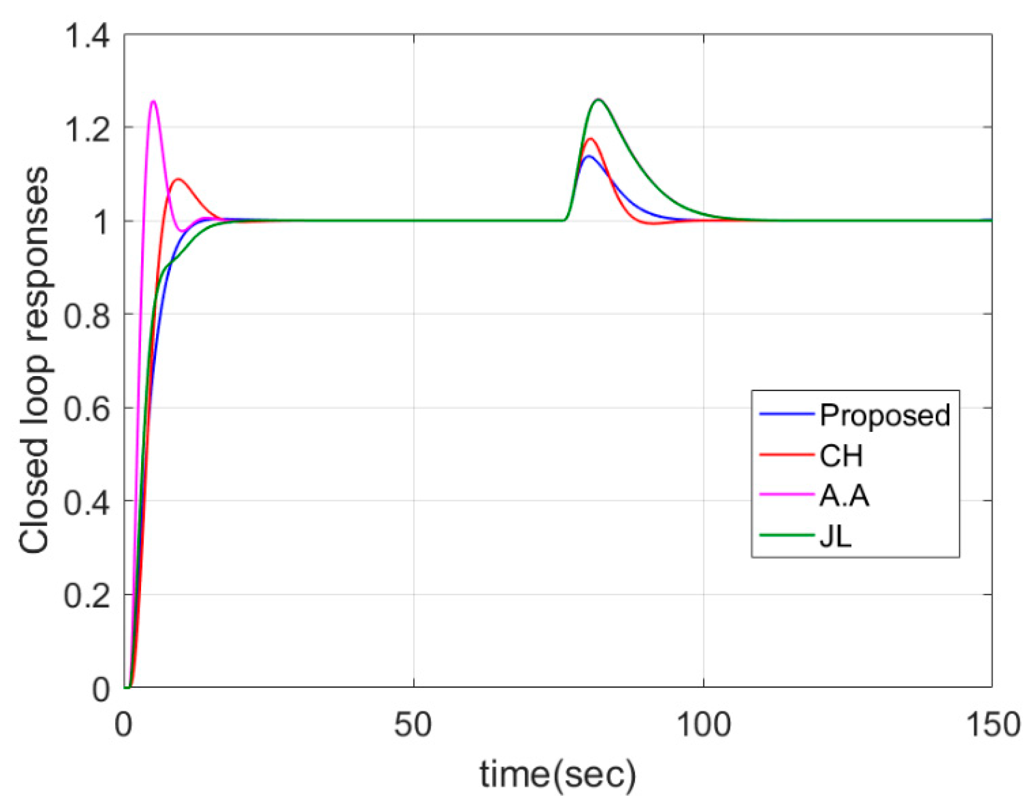
Servo and regulatory step responses of various methods are shown in Figure 13. Figure 14 gives the controller outputs of different methods. From Figure 13, it can be seen that the proposed method has the smallest OS for both servo and regulation problems. Though the method in M. Ajmeri and A. Ali [36] has the smallest IAE, it has a large overshoot and large value of TV at the same time. For the regulation problem, as far as IAE and OS are concerned, the proposed method has almost the best performance.
To test the robustness of the proposed method, parameter perturbations are considered. In simulation, 20% perturbations of all parameters are added, that is, G r = 0.24 e 1.2 s s ( 4.8 s + 1 ) . Figure 15 and Figure 16 give the closed loop responses and controller outputs of different methods. From Figure 15 and Figure 16 and Table 5, it can be seen that the proposed method has minimal OS for both servo problems and adjustment problems. For servo problems, the values of IAE and TV are close to other methods. For regulation problem, the proposed method has the second smallest IAE, which is very close to the method in Ch. Anil and R. Padma Sree (CH) [37].

4.4. Stable FOPTD System with a Negative Zero

Consider a stable FOPTD system with a negative zero given by G p ( s ) = ( 1 + 10 s ) e s s ( 2 s + 1 ) . The proposed method is compared with the method proposed by Ch. Anil and R. Padma Sree [37]. The tuning parameter λ of the proposed method is adjusted to 1.67 in a way that Ms equals to 2.35 as that is given in [37]. The dominant poles and the non-dominant poles are placed at −0.5988 and −2.994, respectively.
Servo and regulatory step responses and the controller outputs are shown in Figure 17. From Figure 17 and Table 4, it can be seen that the servo and regulation performances of the proposed method are better than [37] in terms of IAE, TV and OS.
To test the robustness of the proposed method, parameter perturbations are considered. In simulation, 20% perturbations of all parameters are added, that is, G r = ( 1 + 12 s ) e 1.2 s s ( 2.4 s + 1 ) . Figure 18 gives the closed loop responses and controller outputs of different methods. From Figure 18 and Table 5, it can be seen that the proposed method has smaller IAE, TV and OS for both servo problem and regulation problem.

4.5. High-Order System

To illustrate that the proposed method can also apply to high-order systems, a plant G p ( s ) = 0.5 ( 1 0.5 s ) e 0.7 s s ( 0.4 s + 1 ) ( 0.1 s + 1 ) ( 0.5 s + 1 ) is considered in this section. The process model is reduced by the reduction technique to an FOPTDI model given by G p ( s ) = 0.5183 e 1.2799 s s ( 1.1609 s + 1 ) . The proposed method is compared with the methods proposed by Ch. Anil and R. Padma Sree [37] and Q.B. Jin and Q. Liu [27]. The tuning parameter λ is adjusted to 2.235 to match Ms = 2.81. The dominant poles and the non-dominant poles are placed at −0.4474 and −2.237, respectively.
Servo and regulatory step responses and controller outputs are detailed in Figure 19. From Figure 19 and Table 4, it can be observed that the proposed method has the smallest OS and the IAE and TV performances are close to the methods in Ch. Anil and R. Padma Sree [37] and Q.B. Jin and Q. Liu [27].
Squar up the robustness of the proposed method, parameter perturbations are considered. In simulation, 20% perturbations of all parameters are added, that is, G r = 0.6 ( 1 0.6 s ) e 0.84 s s ( 0.48 s + 1 ) ( 0.12 s + 1 ) ( 0.6 s + 1 ) . Figure 20 gives the closed loop responses and controller outputs of different methods. From Figure 20 and Table 5, it can be seen that the proposed method has the smallest IAE and OS for the servo problem and the TV value is close to other methods. For the regulation problem, the proposed method has the smallest IAE, TV and OS.

4.6. Non-Linear Model

A Continuous Stirred Tank Reactor (CSTR) [35] is considered with model equations expressed as:
d C A d t = F V ( C A F C A ) r
d C B d t = C B F V + r
d T d t = F V ( T F T ) + ( Δ H ) r ρ C p h A V ρ C p ( T T c )
r = k C A e E / R T
Table 6 shows the values of the process parameters.
The above nonlinear equation is linearized near the unstable operating point CAs = 10 K mol/m3, CBs = 5.62 K mol/m3, Ts = 590 K. The transfer function model about the operating temperature to the feed concentration is expressed as:
T ( s ) C A F ( s ) = 0.07803 s + 0.007803 s 3 + 0.1766 s 2 + 0.00735 s 0.000031
Equation (31) can be simplified as
T ( s ) C A F ( s ) = 0.07803 ( 0.1 + s ) ( s + 0.1 ) ( s + 0.0805 ) ( s 0.0039 )
After the pole zero cancellation, Equation (32) can be reduced to:
T ( s ) C A F ( s ) = 0.07803 0.0805 × 0.0039 ( 12.4224 s + 1 ) ( 256.4103 s 1 )
In Equation (33), the unstable time constant with a value of 256.4103 in the denominator is considered into process gain because it is very large. Subsequently, a transfer function of the stable FOPTDI system is obtained as follows:
T ( s ) C A F ( s ) = 0.9693 s ( 12.4224 s + 1 )
Considering the 1 s measurement time delay in Equation (34), the transfer function model is expressed as:
T ( s ) C A F ( s ) = 0.9693 s ( 12.4224 s + 1 ) e s
A conventional PID controller is designed for the transfer function model of Equation (33) by selecting a tuning parameter with a value of 2.5 to match the same Ms as Ch. Anil and R. Padma Sree [35]. Lee et al. [26] proposed a simple analytical PID controller using a modified IMC method, and the PID parameters are obtained by assuming the transfer function model to be an FOPTDI plant. The tuning parameter λ is tuned to 2.5 to match Ms = 2. The dominant poles and the non-dominant poles are placed at −0.4 and −2, respectively.
Servo and regulatory responses and controller outputs of CSTR for the linear model in case 6 ( T ( s ) C A F ( s ) = 0.9693 e s s ( 12.4224 s + 1 ) ) given in Figure 21. From Figure 21 and Table 7, it can be seen that the proposed method has the smallest IAE and OS for servo problem. For the regulation problem, the proposed method has the smallest IAE, TV and OS.
To test the robustness of the proposed method, parameter perturbations are considered. In simulation, 20% perturbations of all parameters are added, that is, G r = 1.1632 e 1.2 s s ( 14.9069 s + 1 ) . Figure 22 gives the closed loop responses and controller outputs of different methods. From Figure 22 and Table 7, it can be seen that the proposed method has the smallest IAE and OS for servo problem and the TV value is close to other methods. For regulation problem, the proposed method has the smallest IAE, TV and OS.
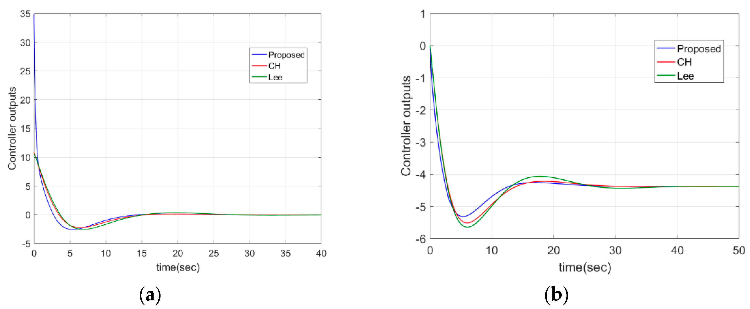
To explain the effectiveness of the method proposed in this article for nonlinear plant, simulations for the non-linear model are given. Figure 23 gives the servo responses and controller outputs of the non-linear model in case 6 for a step change in operating temperature from 590 K to 595 K. Figure 24 gives the regulatory responses and controller outputs of non-linear model in case 6 for a load change of feed concentration from 15.61 to 20 K mol/m3. Table 8 concludes the performance comparison of the CSTR nonlinear model in terms of IAE, TV and OS. From Table 7, it can be proved that the proposed method has the best performances for both servo and regulation problems.
From the above simulations, it can be concluded that the proposed method is superior to other methods in terms of IAE values and overshoot for both linear model and non-linear model of CSTR.

5. Conclusions

In this paper, a novel analytical tuning rule of a PID controller is proposed for integrating systems with time delay using the direct synthesis method and modified multiple dominant pole-placement method. A combination of third-order dominant poles and second-order non-dominant poles is adopted to achieve better performances. When using the analytical formula, the PID parameters can be directly calculated. According to the adjustment parameters and Ms, the adjustment rules are given to meet the required robustness and performance requirements.
Compared with other methods, the designed controller is found to be more effective in terms of IAE, TV and OS for both servo and regulation problems from simulation results. The controller used in this paper is a conventional PID control scheme. In the future, a differential forward PID control scheme or other advanced control schemes, such as a parallel control system and cascade control structure, can be considered to further improve the performance and robustness.

Author Contributions

W.Z. and Y.C. designed the experiments; W.Z. wrote the paper and completed simulation; Y.C. and X.D. processed experimental results, checked the paper. All authors have read and agreed to the published version of the manuscript.

Funding

This research was funded by the National Science Foundation of China (11502145, 61703277, 61673276, 61473183, and 61074087), and Shanghai Aerospace Science and Technology Innovation Foundation (SAST2018-022).

Conflicts of Interest

The authors declare no conflict of interest.

References

  1. Kumar, D.B.S.; Padma Sree, R. Tuning of IMC based PID controllers for integrating systems with time delay. ISA Trans. 2016, 63, 242–255. [Google Scholar] [CrossRef]
  2. Zhang, W.D. Quantitative Process Control Theory; CRC Press Inc.: Boca Raton, FL, USA, 2011. [Google Scholar]
  3. Ali, A.; Majhi, S. PID controller tuning for integrating processes. ISA Trans. 2010, 49, 70–78. [Google Scholar] [CrossRef]
  4. Krishna, D.; Suryanarayana, K.; Aparna, G.; Padma Sree, R. Tuning of PID controllers for continuous stirred tank reactors. Indian Chem. Eng. 2012, 54, 157–179. [Google Scholar] [CrossRef]
  5. Makaremi, I.; Labibi, B. Control of a distillation column: A decentralized approach. In Proceedings of the IEEE International Symposium on Computer Aided Control System Design, Anchorage, AK, USA, 25–27 September 2000; IEEE: New York, NY, USA, 2009. [Google Scholar]
  6. Zhou, L.; Sun, X. The study of boiler control system of water level of steam drum based on new immune PID controller. In Proceedings of the Second International Conference on Digital Manufacturing & Automation, Zhangjiajie, Hunan, China, 5–7 August 2011. [Google Scholar]
  7. Zhao, R.X.; Wang, X.J.; Teng, F. The PID control system of steam boiler drum water level based on genetic algorithms. In Proceedings of the Guidance, Navigation & Control Conference, Yantai, Shandong, China, 8–10 August 2014; IEEE: New York, NY, USA, 2014. [Google Scholar]
  8. Wang, L.; Cluett, W.R. Tuning PID controllers for integrating processes. IEE Proc. Control. Theory Appl. 1997, 144, 385–392. [Google Scholar] [CrossRef]
  9. Bequette, B.W. Process Control: Modeling, Design, and Simulation; Prentice Hall PTR: Upper Saddle River, NJ, USA, 2003. [Google Scholar]
  10. Kaya, I. Two-degree-of-freedom IMC structure and controller design for integrating processes based on gain and phase-margin specifications. IEE Proc. Control. Theory Appl. 2004, 151, 481–487. [Google Scholar] [CrossRef]
  11. Rao, C.V.N.; Padma Sree, R. IMC based controller design for integrating systems with time delay. Indian Chem. Eng. 2011, 52, 194–218. [Google Scholar] [CrossRef]
  12. Rao, A.S.; Rao, V.S.R.; Chidambaram, M. Direct synthesis-based controller design for integrating processes with time delay. J. Frankl. Inst. 2009, 346, 38–56. [Google Scholar]
  13. Vanavil, B.; Chaitanya, K.K.; Rao, A.S. Improved PID controller design for unstable time delay processes based on direct synthesis method and maximum sensitivity. Int. J. Syst. Sci. 2015, 46, 1349–1366. [Google Scholar] [CrossRef]
  14. Silva, L.R.D.; Flesch, R.C.C.; Normey-Rico, J.E. Controlling industrial dead-time systems: When to use a PID or an advanced controller. ISA Trans. 2020, 99, 339–350. [Google Scholar] [CrossRef]
  15. Fiser, J.; Zitek, P. PID Controller Tuning via Dominant Pole-placement in Comparison with Ziegler-Nichols Tuning. In Proceedings of the 15th IFAC Workshop on Time Delay Systems (TDS) Jointly Held with the 7th IFAC Symposium on System Structure and Control (SSSC), Sinaia, Romania, 9–11 September 2019; IFAC: New York, NY, USA, 2019; pp. 43–48. [Google Scholar]
  16. Alfaro, V.M.; Vilanova, R. Model reference robust tuning of 2DoF PI controllers for integrating controlled processes. In Proceedings of the Control & Automation, Barcelona, Spain, 3–6 July 2012; IEEE: New York, NY, USA, 2012. [Google Scholar]
  17. Alfaro, V.M.; Vilanova, R. Robust tuning and performance analysis of 2DoF PI controllers for integrating controlled processes. Ind. Eng. Chem. Res. 2012, 51, 13182–13194. [Google Scholar] [CrossRef]
  18. Chriss, G.; Sigurd, S. Optimal pi and pid control of first-order plus delay processes and evaluation of the original and improved simc rules. J. Proc. Control 2018, 70, 36–46. [Google Scholar]
  19. Madhuranthakam, C.R.; Singh, J.; Elkamel, A.; Budman, H. Optimal PID controller parameters for first order and second order systems with time delay using a connectionist approach. Eng. Opt. 2010, 42, 295–303. [Google Scholar] [CrossRef]
  20. Boskovic, M.; Sekara, T.B.; Rapaic, M.R. Novel tuning rules for PIDC and PID load frequency controllers considering robustness and sensitivity to measurement noise. Int. J. Electr. Power Energy Syst. 2020, 114, 105416. [Google Scholar] [CrossRef]
  21. Persson, P.; Aström, K.J. PID control revisited. IFAC Proc. Vol. 1993, 26, 451–454. [Google Scholar] [CrossRef]
  22. Padma Sree, R.; Chidambaram, M. Set point weighted PID controllers for unstable systems. Chem. Eng. Commun. 2005, 192, 1–13. [Google Scholar] [CrossRef]
  23. Uma, S.; Chidambaram, M.; Rao, A.S.; Yoo, C.K. Enhanced control of integrating cascade processes with time delays using modified Smith predictor. Chem. Eng. Sci. 2010, 65, 1065–1075. [Google Scholar] [CrossRef]
  24. Shamsuzzoha, M.; Lee, M. PID controller design for integrating processes with time delay. Korean J. Chem. Eng. 2008, 25, 637–645. [Google Scholar] [CrossRef]
  25. Vu, T.N.L.; Lee, M. A unified approach to the design of advanced proportional-integral-derivative controllers fortime delay processes. Korean J. Chem. Eng. 2013, 30, 546–558. [Google Scholar] [CrossRef]
  26. Lee, J.; Cho, W.; Edgar, T.F. Simple analytic PID controller tuning rules revisited. Ind. Eng. Chem. Res. 2014, 53, 5038–5047. [Google Scholar] [CrossRef]
  27. Jin, Q.B.; Liu, Q. Analytical IMC-PID design in terms of performance/robustness tradeoff for integrating processes: From 2-Dof to 1-Dof. J. Proc. Control 2014, 24, 22–32. [Google Scholar] [CrossRef]
  28. Santosh, S.; Chidambaram, M. A simple method of tuning parallel cascade controllers for unstable FOPTD systems. ISA Trans. 2016, 65, 475–486. [Google Scholar] [CrossRef]
  29. Shamsuzzoha, M. Closed-loop PI/PID controller tuning for stable and integrating process with time delay. Indust. Eng. Chem. Res. 2013, 52, 12973–12992. [Google Scholar] [CrossRef]
  30. Valentine, C.C.; Chidambaram, M. PID Control of unstable time delay systems. Chem. Eng. Commun. 1997, 162, 63–74. [Google Scholar] [CrossRef]
  31. Wang, Q.G.; Zhang, Z.; Astrom, K.J.; Chek, L.S. Guaranteed dominant pole-placement with PID controllers. J. Proc. Control 2009, 19, 349–352. [Google Scholar] [CrossRef]
  32. Viteckova, M.; Vitecek, A. Use of multiple dominant pole method for controller tuning. In Proceedings of the Carpathian Control Conference, High Tatras, Slovakia, 28–31 May 2012; IEEE: New York, NY, USA, 2012. [Google Scholar]
  33. Viteckova, M.; Vitecek, A. Two-degree of freedom controller tuning for integral plus time delay plants. ICIC Exp. Lett. 2008, 2, 225–229. [Google Scholar]
  34. Viteckova, M.; Vitecek, A. 2DOF PID controller tuning for integrating plants. In Proceedings of the Carpathian Control Conference, Tatranska Lomnica, Slovakia, 29 May–1 June 2016; IEEE: New York, NY, USA, 2016. [Google Scholar]
  35. Anil, C.; Padma Sree, R. PID control of integrating systems using multiple dominant pole-placement method. Asia Pac. J. Chem. Eng. 2015, 10, 734–742. [Google Scholar] [CrossRef]
  36. Ajmeri, M.; Ali, A. Direct synthesis based tuning of the parallel control structure for integrating processes. Int. J. Syst. Sci. 2015, 46, 2461–2473. [Google Scholar] [CrossRef]
  37. Anil, C.; Padma Sree, R. Tuning of PID controllers for integrating systems using direct synthesis method. ISA Trans. 2015, 57, 211–219. [Google Scholar] [CrossRef]
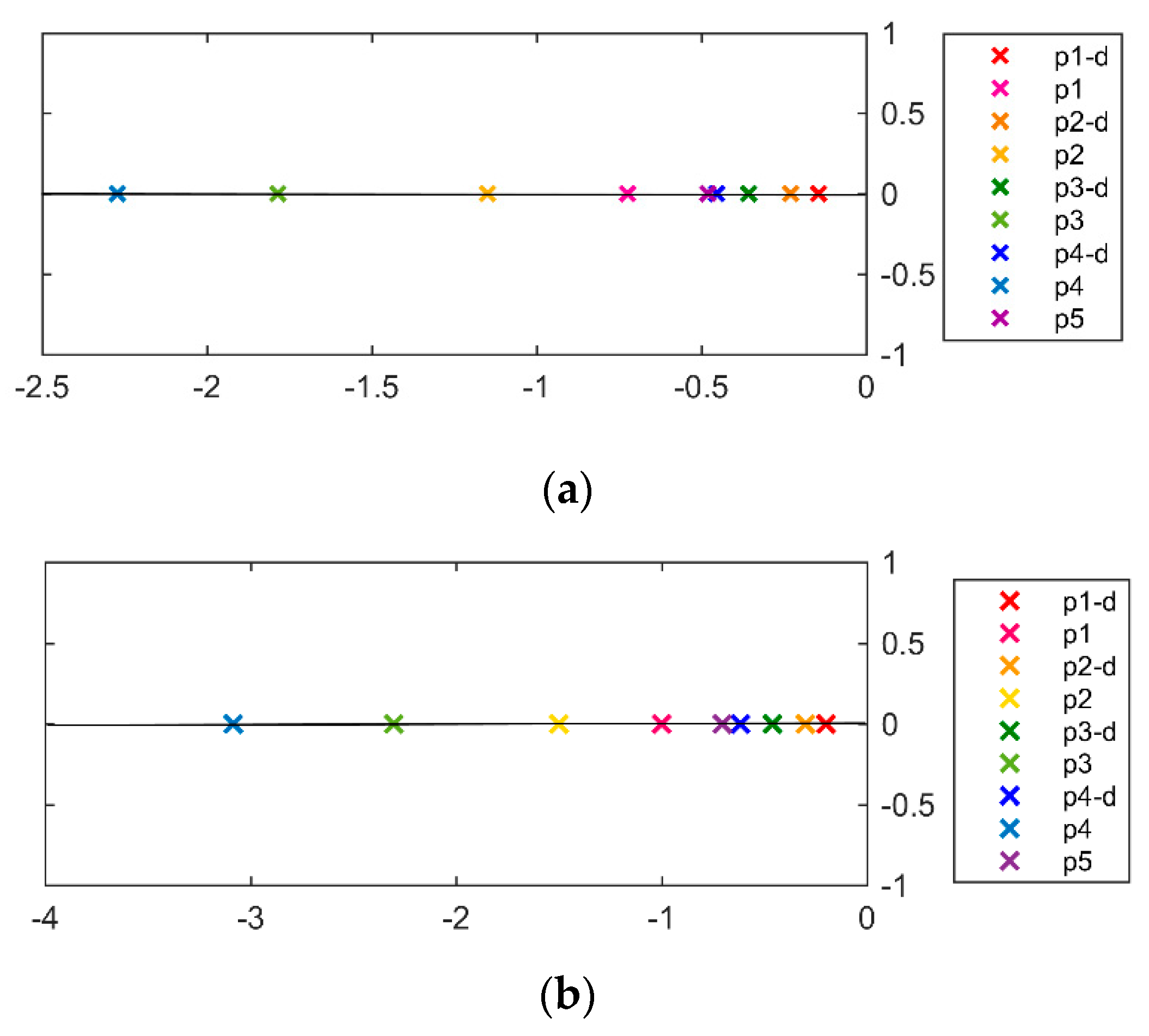
Figure 1. Locations of 1st-order, 2nd-order, 3rd-order, 4th-order dominant poles with their corresponding non-dominant poles and fifth-order dominant poles for a double integral plus time delay system (DIPTD) system (a) and a first-order plus integral time delay system (FOPTDI) system (b) with Ms = 2.
Symmetry 12 01449 g001
Figure 2. Step response of the closed-loop systems consist of 1st-order, 2nd-order, 3rd-order, 4th-order dominant poles with their corresponding non-dominant poles (solid line) and the step response of the systems consist of only dominant poles (dotted line) for a DIPTD system (a) and an FOPTDI system (b) with Ms = 2.
Symmetry 12 01449 g002
Figure 3. Responses of the systems consist of dominant poles with their corresponding non-dominant poles (a) and responses of the systems consist of only dominant poles (b) for a DIPTD system with Ms = 2.
Symmetry 12 01449 g003
Figure 4. Variation of Ms with λ/L for IPTD (a) and DIPTD (b) systems.
Symmetry 12 01449 g004
Figure 5. Servo step responses and regulatory step responses of case 1.
Symmetry 12 01449 g005
Figure 6. Controller outputs of servo (a) and regulatory (b) of case 1.
Symmetry 12 01449 g006
Figure 7. Servo step responses and regulatory step responses of case 1 with parameter mismatch (time delay +40%).
Symmetry 12 01449 g007
Figure 8. Controller outputs of servo (a) and regulatory (b) of case 1 with parameter mismatch (time delay +40%).
Symmetry 12 01449 g008
Figure 9. Servo (a) and regulatory (b) responses of case 2.
Symmetry 12 01449 g009
Figure 10. Controller outputs of servo (a) and regulatory (b) of case 2.
Symmetry 12 01449 g010
Figure 11. Servo (a) and regulatory (b) responses of case 2 with parameter mismatch (time delay +40%).
Symmetry 12 01449 g011
Figure 12. Controller outputs of servo (a) and regulatory (b) of case 2 with parameter mismatch (time delay +40%).
Symmetry 12 01449 g012
Figure 13. Servo and regulatory responses of case 3.
Symmetry 12 01449 g013
Figure 14. Controller outputs of servo (a) and regulatory (b) of case 3.
Symmetry 12 01449 g014
Figure 15. Servo step responses and regulatory step responses of case 3 with parameter mismatch (all parameters +20%).
Symmetry 12 01449 g015
Figure 16. Controller outputs of servo (a) and regulatory (b) of case 3 with parameter mismatches (all parameters +20%).
Symmetry 12 01449 g016
Figure 17. Servo and regulatory responses (a) and controller outputs (b) of case 4.
Symmetry 12 01449 g017
Figure 18. Servo and regulatory responses (a) and controller outputs (b) of case 4 with parameter mismatches (all parameters +20%).
Symmetry 12 01449 g018
Figure 19. Servo and regulatory responses (a) and controller outputs (b) of case 5.
Symmetry 12 01449 g019
Figure 20. Servo and regulatory responses (a) and controller outputs (b) of case 5 with parameter mismatches (all parameters +20%).
Symmetry 12 01449 g020
Figure 21. Servo and regulatory responses (a) and controller outputs (b) of linear model of case 6.
Symmetry 12 01449 g021
Figure 22. Servo and regulatory responses (a) and controller outputs (b) of linear model of case 6 with parameter mismatches (all parameters +20%).
Symmetry 12 01449 g022
Figure 23. Servo responses (T from 344 K to 346 K) (a) and regulatory responses (Tj from 317.4 K to 310 K) (b) of jacketed CSTR for the non-linear model in case 6.
Symmetry 12 01449 g023
Figure 24. Controller outputs (T from 344 K to 346 K) (a) and (Tj from 317.4 K to 310 K) (b) of jacketed CSTR for non-linear model in case 6.
Symmetry 12 01449 g024
Table 1. Proportional-Integral-Derivative (PID) tuning rules for IPTD and DIPTD.
ProcessControllerPID Parameters with Filter
k p e L s s k c ( 1 + 1 τ i s + τ d s ) 1.5     Ms     3.2 λ L = 1.333 + 9.567 M s 4.882
τ i = 7 λ 3 + 0.5 L
τ d = 5 λ 2 6 τ i + 0.25 L λ 3 3 L τ i
k c = ( k p ( 5 λ 2 3 τ i + 0.5 L τ d ) ) 1
k p e L s s 2 k c ( 1 + 1 τ i s + τ d s ) ( α s + 1 β s + 1 ) 1.8     Ms     4.8 λ L = 13.11 M s 3.301 + 1.493
τ i L = 3.628 ( λ L ) 0.9645 0.2809
τ d L = 1.356 ( λ L ) 0.9521 0.1023
k p k c L 2 = 1.181 ( λ L ) 1.745 0.01631
α L = 0.6381 ( λ L ) 0.03749 0.117 ( λ L 2.5 )
α L = 7.942 × 10 7 ( λ L ) 8.862 + 0.4961   ( λ L 2.5 )
β L = 0.02922 ( λ L ) 2.124 0.001047
Table 2. PID tuning rules for FOPTDI (Ms = 2).
ProcessControllerPID Parameters with Filter
k p e L s s ( τ s + 1 ) k c ( 1 + 1 τ i s + τ d s ) ( α s + 1 β s + 1 ) λ τ = 1.679 ( L τ ) 0.6607 0.1258
τ i τ = 3.44 ( λ τ ) 0.9723 0.050775
τ d τ = 0.81325 ( λ τ ) 0.3116 + 1.50325
k p k c τ = 1.5844 ( λ τ ) 1.946 + 0.19484
α τ = 0.2467 ( λ τ ) 1.685 + 0.034425
β τ = 0.074225 ( λ τ ) 0.9926 + 3.2825 × 10 3
Table 3. PID settings for cases 1–6.
Transfer FunctionMethod τiτdkcαβMs
Case 1:
G p = 0.05 e 5 s s
Proposed21.42.14933.6627--2
V.V a18.661.32003.1400--2
A.A20.5751.77053.3209--2
CH18.941.893.727--2
Case 2:
G p = e s s 2
Proposed9.59123.54030.17680.49670.26382
CH9.72643.82110.13781.07611.03922
JL b21.2817.25500.0460--2
A.A22.487.84150.0414--2
Case 3:
G p = 0.2 e s s ( 4 s + 1 )
Proposed7.43692.0356.67350.49370.1762
CH5.90461.95195.74220.63200.49152
A.A10.42212,47693.67--2
JL c10.3922.47303.6860--1.998
Case 4:
G p = ( 1 + 10 s ) e s s ( 2 s + 1 )
Proposed d5.65941.29561.2179--2.350
CH e5.15361.24581.1601--2.350
Case 5:
G p = 0.5 ( 1 0.5 s ) e 0.7 s s ( 0.4 s + 1 ) ( 0.1 s + 1 ) ( 0.5 s + 1 )
Proposed7.19910.64220.96841.03990.20982.81
JL f8.69801.12000.9700--2.81
CH6.37920.65731.00301.16080.5492.81
Case 6:
T ( s ) C A F ( s ) = 0.9693 e s s ( 12.4224 s + 1 )
Proposed8.50002.80343.00210.50000.21532
CH2.13078.97753.10331.011912
Lee2.11716.36303.1860--2
a Set point filter: 15.616 s 2 + 7.89318 s + 1 24.6312 s 2 + 18.66 s + 1 b Set point filter: 46.0093 s 2 + 13.513 s + 1 154.393655 s 2 + 21.281 s + 1 . c Set point filter: 9.7915 s 2 + 6.266 s + 1 25.699 s 2 + 10.392 s + 1 d PID filter: 0.5186 s + 1 1.118 s 2 + 10.1118 s + 1 . e PID filter: 0.5214 s + 1 2.674 s 2 + 10.2674 s + 1 f Set point filter: 2.25 s 2 + 4.045 s + 1 9.74 s 2 + 8.698 s + 1 .
Table 4. Performance comparison in terms of Integral Absolute Error (IAE), Total Variation (TV) and OS (Maximum overshoot) for step responses.
Transfer FunctionMethod Servo ProblemRegulation Problem
IAETVOSIAETVOS
Case 1:
G p = 0.05 e 5 s s
Proposed12.843.8105.792.000.3
CH11.423.890.005.072.020.31
V.V11.563.810.035.941.900.34
A.A7.1536.580.076.172.780.32
Case 2:
G p = e s s 2
Proposed5.810.21054.303.755.17
CH5.980.150.0170.762.547.06
A.A5.463.160.22541.193.1020.27
JL7.760.220486.062.1518.66
Case 3:
G p = 0.2 e s s ( 4 s + 1 )
Proposed4.5220.560.001.122.820.14
CH4.519.920.0891.102.350.17
A.A3.1340.210.2562.841.850.26
JL4.1317.540.002.831.860.26
Case 4:
G p = ( 1 + 10 s ) e s s ( 2 s + 1 )
Proposed4.050.380.3313.662.054.67
CH4.340.400.5217.042.225.03
Case 5:
G p = 0.5 ( 1 0.5 s ) e 0.7 s s ( 0.4 s + 1 ) ( 0.1 s + 1 ) ( 0.5 s + 1 )
Proposed4.433.450.017.533.060.97
CH4.101.670.026.512.751.07
JL4.683.200.009.032.571.15
Table 5. Performance comparison in terms of IAE, TV and OS (maximum overshoot) step responses with model mismatches.
Transfer FunctionMethod Servo ProblemRegulation Problem
IAETVOSIAETVOS
Case 1:
Time delay +40% G r = 0.05 e 7 s s
Proposed14.957.570.126.084.200.39
CH16.959.270.256.794.970.40
V.V18.537.810.308.494.130.44
A.A15.2842.610.416.794.960.42
Case2:
Time delay +40%
G p = e 1.4 s s 2
Proposed4.700.560.0654.334.566.13
CH6.030.260.0270.864.168.25
A.A6.043.220.31542.564.6321.12
JL7.760.250462.712.8319.98
Case3:
parameters +20% G r = 0.24 e 1.2 s s ( 4.8 s + 1 )
Proposed4.4616.5201.113.980.16
CH4.4110.030.131.053.340.20
A.A4.4044.140.452.842.490.29
JL4.1319.4802.832.510.29
Case 4:
parameters +20% G p = ( 1 + 10 s ) e s s ( 2 s + 1 )
Proposed4.370.530.6017.363.475.50
CH5.080.660.8225.684.345.87
Case 5:
parameters +20% G r = 0.6 ( 1 0.6 s ) e 0.84 s s ( 0.48 s + 1 ) ( 0.12 s + 1 ) ( 0.6 s + 1 )
Proposed4.585.390.057.586.001.35
CH5.974.830.218.318.121.47
JL5.655.350.109.967.101.56
Table 6. Parameter values for a continuous stirred tank reactor (CSTR).
ParameterValue
Volume, V50 m3
Feed flow rate, F5 m3/s
Feed temperature, TF580 K
Feed concentration, CAF15.61 K mol/m3
Heat transfer coefficient, hA2600 kJ/(min K)
Specific heat, Cp1.8 kJ/(kg K)
Heat of reaction, −ΔH20,000 kJ/kmol
Universal gas law constant, R8.314 kJ/(kmol K)
Activation energy, E80,000 kJ/kmol
Frequency factor, k680,000 min−1
Density, ρ800 kg/m3
Temperature, Tc401.6 K
Table 7. CSTR for linear model and added 20% perturbations in terms of IAE, TV and OS (Maximum overshoot) step responses.
Transfer FunctionMethod Servo ProblemRegulation Problem
IAETVOSIAETVOS
T ( s ) C A F ( s ) = 0.9693 e s s ( 12.4224 s + 1 ) Proposed5.7910.950.322.832.950.30
CH6.994.940.434.223.320.46
Lee7.635.450.553.703.570.45
parameters +20%
G r = 1.1632 e 1.2 s s ( 14.9069 s + 1 )
Proposed5.9613.790.372.833.550.34
CH7.186.570.524.223.970.51
Lee7.676.830.653.544.130.50
Table 8. Performance comparison in terms of IAE, TV and OS for non-linear model of CSTR.
Method For Step Change of Operating Temperature from 590 to 595 KFor Load Change of Feed Concentration from 15.61 to 20 K mol/m3
IAETVOSIAETVOS
Proposed26.6240.360.002412.416.511.2
CH31.3815.570.002918.746.981.7
Lee34.2016.550.003616.697.671.6