Article

Analytical Calculation of the Tooth Surface Contact Stress of Cylindrical Gear with Variable Hyperbolic Circular-Arc-Tooth-Trace

1
School of Mechanical and Electrical Engineering, Lanzhou University of Technology, Lanzhou 730050, China
2
Hubei Key Laboratory of Mechanical Transmission and Manufacturing Engineering, Wuhan 430081, China
*
Author to whom correspondence should be addressed.
Symmetry 2020, 12(8), 1318; https://doi.org/10.3390/sym12081318
Submission received: 27 May 2020 / Revised: 28 July 2020 / Accepted: 3 August 2020 / Published: 6 August 2020

Abstract

:
In order to theoretically research the tooth surface maximum contact stress of a Cylindrical Gear with Variable Hyperbolic Circular-Arc-Tooth-Trace (VH-CATT), the computing formula of maximum contact stress of VH-CATT cylindrical gear is investigated according to Hertz formula in this paper. Insufficient contact fatigue strength will lead to pitting corrosion, plastic deformation of tooth surface and other damages. Therefore, the maximum contact stress of tooth surface must be carried out. The contact stress calculation formula is particularly considering the effect of normal force, total carrying length, synthetical curvature radius, and position angle. The present work establishes analytical solutions to research the effect of different parameters for the contact stress of VH-CATT cylindrical gear incorporating elastic deformation on the tooth surface, and which have shown that the different module, transmission ratio, pressure angle, tooth width, and the cutter head radius have a crucial effect on the contact stress and contact ellipse of VH-CATT cylindrical gear along the tooth width direction. Moreover, a finite element analysis is carried out to verify the correctness of the theoretical computing formula of contact stress of VH-CATT cylindrical gear. By contrast with the theoretical calculated value and the stress value of finite element analysis, its error is very small. It is indicated that the derived formula of contact fatigue strength of VH-CATT cylindrical gear has high accuracy and can accurately reflect the real contact stress value of tooth surface, which is beneficial for research on tooth break reduction, pitting, wear resistance and fatigue life improvement of the VH-CATT cylindrical gear. The study results also have a certain reference value for the design and check calculation of the VH-CATT cylindrical gear.

1. Introduction

At present, gear transmission, as one of the most widely used transmission modes in the machinery industry, is focused on the optimization and improvement about transmission performance, service life, structure, etc. [1,2,3]. The Cylindrical Gear with Variable Hyperbolic Circular-Arc-Tooth-Trace (VH-CATT) is a kind of mechanical transmission part, which is different from the traditional gear in tooth line and tooth profile and depending on its distinguished advantages. Comparing with the involute spur gear and helical gear, the VH-CATT cylindrical gear has the arc tooth line as well as better meshing performance, that it has bigger contact ratio and no axial force [4,5,6,7,8]. This transmission has stable characteristic, low noise and high reliability, and the VH-CATT cylindrical gear will have a good application prospect.
The surface feature of VH-CATT cylindrical gear is so complex that the contact condition of gear pair is more complicated than the traditional gear pair. The contact characteristic of VH-CATT cylindrical gear has a great influence on the gear’s stability, reliability, structur, and noise [9,10,11]. The stress distribution of tooth surface affects the contact characteristic and the contact fatigue life of VH-CATT cylindrical gear. The poor design of contact fatigue strength will lead to pitting corrosion, plastic deformation of tooth surface and other damages. Therefore, the design process of the entire VH-CATT cylindrical gear pair needs to be optimized, and it will be hindered by the complexity of the contact phenomenon. For the moment, there are some researches on VH-CATT, including undercutting [12], gear machining [13], 3D modeling [14], and contact analysis [6]. However, there is no uniform and applied formula for calculating the contact fatigue strength of the VH-CATT cylindrical gear up to now. So, the calculating formula of contact fatigue strength of tooth surface must be accurately derived. The contact fatigue strength of the VH-CATT cylindrical gear with the material 45 steel is investigated, which can provide the reference for calculating the contact strength of VH-CATT cylindrical gear. By contrasting the helical gear, the contact fatigue strength of the VH-CATT cylindrical gear is increased by 26% and the pitting corrosion resistance is also improved [15]. Gear meshing is a common nonlinear contact. At present, the most effective method to solve nonlinear problems is the finite element method. The numerical analysis of gear strength is a small deformation problem, which accords with the basic conditions of statics. In the cause of evaluating the quality of gear pair under loading conditions, it is a common practice that extend gear contact analysis to the finite element analysis (FEA) of gear pair. According to the ansys parametric design language (APDL), Ruyang Wu and others establish the ideal identity model of tooth profile and gear based on ideal tooth profile equation, and it gets the ideal gear profile in meshing period and change curve of maximum contact stress with position of gear meshing [16]. In Morrish Kumar’s and others work. An investigation has been done numerically using FEA software on an asymmetric gear tooth with circular holes as Stress relieving features for the structural analysis under some pre-defined loading value [17]. The mathematical model of curvilinear cylindrical gears machined by the same face-milling cutter is established and the undercutting conditions and contact characteristics of VH-CATT cylindrical gear were analyzed according to Litvin’s research method [18]. A mathematical model of curvilinear cylindrical gear with variable tooth trace generated by a pair of independent face milling cutters was proposed, and its contact characteristics were analyzed, and the stress analysis was accomplished [19]. The geometric mathematical model of that type of gear was given a description, and their undercutting conditions and contact characteristics were analyzed [20]. The main curvature and normal curvature are the basic parameters which reflect the contact stress of tooth surface [8,21]. The gear’s transmission quality is determined by the curvature relationship of the conjugate tooth surfaces of the gear pair. And the contact form, contact characteristic and the contact stress of gear pairs are also determined by the curvature of tooth surface. Sun [22] derived the checking formula for contact strength of the VH-CATT cylindrical gear, but the change of curvature of tooth surface effecting on the contact stress isn’t considered in the reference.
So far, the basic form of contact strength calculation formula of the VH-CATT cylindrical gear are proposed based on the Hertz formula, but the mentioned formula cannot accurately reflect the contact stress and can’t be used to gear strength check. Some studies used FEA to analyze the contact strength, but the result was only a qualitative analysis. In order to obtain an accurate contact status between two meshing geometries, it requires an accurate formula to describe the contact characteristic. According to the tooth surface equation and the Hertz formula, the computing formula of contact fatigue strength of VH-CATT cylindrical gear is derived in this paper. The effect laws of design parameters on contact ellipse, stress variation and distribution in meshing process are computed and analyzed based on the computing formula. Moreover, a FEA will be carried out to verify the correctness of the theoretical computing formula of contact stress and the contact form of VH-CATT cylindrical gear.

2. Materials and Methods

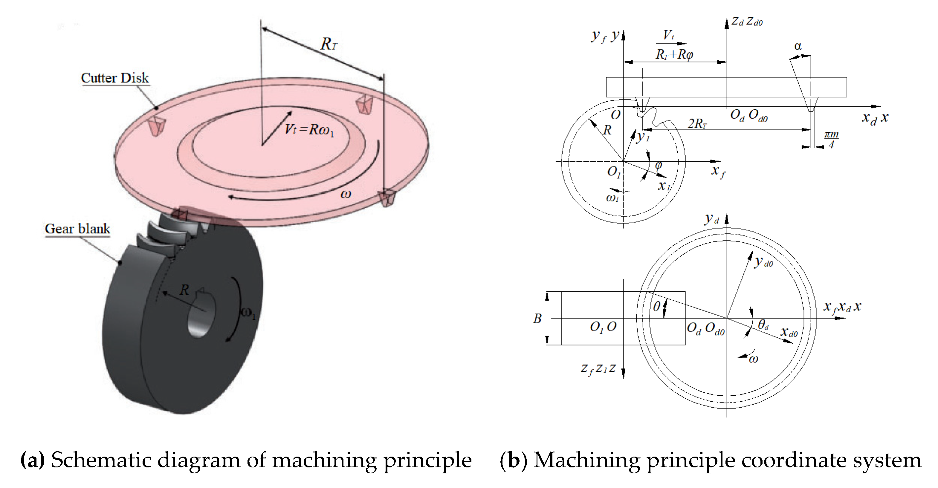
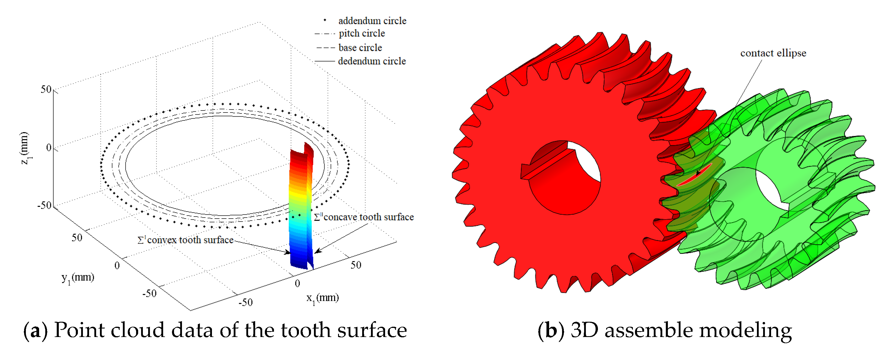
2.1. Math Equation for Tooth Surface of VH-CATT Cylindrical Gear

The processing method of VH-CATT cylindrical gear is similar to the processing method of hyperbolic bevel gear, which is completed by the mutual movement of the gear blank and the cutter installed on the rotating shaft. In the forming process of gear teeth, there is a fixed angle between the inside and outside cutting edge of tool and the tool axis, which is called as the pressure angle of cutting tool. The two conical surfaces will be formed in the cutting process of double edge cutting tool. The concave tooth surface is cut by the outside cutting edge, the convex tooth surface is cut by the inner cutting edge. Therefore, the concave tooth surface and convex tooth surface of VH-CATT cylindrical gear will be formed by the closely generating motion of the gear blank and the cutting tool.
The forming principle of VH-CATT cylindrical gear is shown as Figure 1, where the Coordinate system S d 0 ( x d 0 , y d 0 , z d 0 ) is the moving coordinate system which is attached to the cutter. Coordinate system S d ( x d , y d , z d ) is the static coordinate system which is fixed to the center of cutter. Coordinate system S 1 ( x 1 , y 1 , z 1 ) is the moving coordinate system which is fixed to the gear blank. Coordinate system S ( x , y , z ) is the reference coordinate system. Coordinate system S f ( x f , y f , z f ) is the auxiliary coordinate system.
In Figure 1, where R T is the radius of the cutter. R is the radius of the pitch circle of the gear. B is the tooth width of the gear. ω 1 is the angular velocity at which the gear rotates. ω is the angular velocity at which the cutter rotates. V t is the speed at which the tool moves.
According to the spatial meshing principle and differential geometry, based on the surface parameter equation of cutting tool and the corresponding coordinate transformation matrix, the math equation for tooth surface of VH-CATT cylindrical gear is obtained with the relationship of mutual movement between cutter and gear blank. The math equation for tooth surface is given in the Equation (1). The specific derivation process of tooth surface equation has been given in the literature [8,14].
{ x = [ ( ± u sin α + R T ± π m 4 ) cos θ + R T + R φ ] cos φ ( R + u cos α ) sin φ y = [ ( ± u sin α + R T ± π m 4 ) cos θ + R T + R φ ] sin φ + ( R + u cos α ) cos φ z = ( ± u sin α + R T ± π m 4 ) sin θ u = sin α cos θ [ cos θ ( R T ± π m 4 ) ( R T + R φ ) ] ,
where φ is the rotation angle of gear blank. The ± represent the concave tooth surface and convex tooth surface of the VH-CATT cylindrical gear. The tooth surface is the formed enveloping surface expressed by cutter parameter θ and rotation angle parameter φ .
As the forming principle of VH-CATT cylindrical gear is formed by the cutting edge with the cutter rotary process to form two conical surfaces, where the outer cutting edge (positive cone) cutting concave surface, the inner cutting edge (inverted cone) cutting the convex surface, resulting in the formation of tooth surface of cutter radius different, so that the variable hyperbolic cylindrical gear tooth surface in the meshing process is the point contact. VH-CATT cylindrical gear undergoes elastic deformation during engagement, and their instantaneous contact point area expands into an elliptical region. The center of the instantaneous contact ellipse coincides with the center of the theoretical tangent contact, and the contact traces formed are a set of contact ellipses.
Based on the tooth surface equation and gear parameters in Table 1, the point cloud data of concave and convex tooth surface of VH-CATT cylindrical gear are generated using the MATLAB. From Figure 2a, the left tooth surface is the concave tooth surface which is cut by the outside cutting edge of the cutter; the right tooth surface is the convex tooth surface which is cut by the inner cutting edge of cutter. The point cloud data of tooth surface is imported into Unigraphics NX (UG). The point cloud forms a curved surface and entity with the UG. The 3D assemble modeling of the VH-CATT cylindrical gear is shown in Figure 2b.
The 3D assemble modeling of the VH-CATT cylindrical gear is the basic of FEA. From the assemble modeling shown in Figure 2b, it is known that the contact form of the VH-CATT cylindrical gear is the ellipse contact under the load. Theoretically speaking the contact form of the VH-CATT cylindrical gear is the point contact. The contact surfaces of VH-CATT cylindrical gear are the concave and convex tooth surface. The principal curvatures and directions of tooth surface are changing in meshing. A pair of VH-CATT cylindrical gear can be regarded as the contact of two cylinders whose radii are equal to the curvature radii at the contact point of the concave and convex tooth profiles respectively.

2.2. Computing Formula of Maximum Contact Stress of VH-CATT Cylindrical Gear

In general, the tooth surface fatigue pitting is one of the main failure reasons of transmission device. The tooth surface fatigue pitting is connected with the tooth surface contact stress. The poor design of contact fatigue strength will lead to pitting corrosion, plastic deformation of tooth surface and other damages. Therefore, the contact fatigue strength check of tooth surface must be carried out. Based on the elastic mechanics, the maximum contact stress of the two parallel cylinder gears under the mutual compression of normal force can be calculated by the Hertz formula. According to Hertz formula, the computing formula of tooth surface maximum contact stress of the VH-CATT cylindrical gear can be established as following.

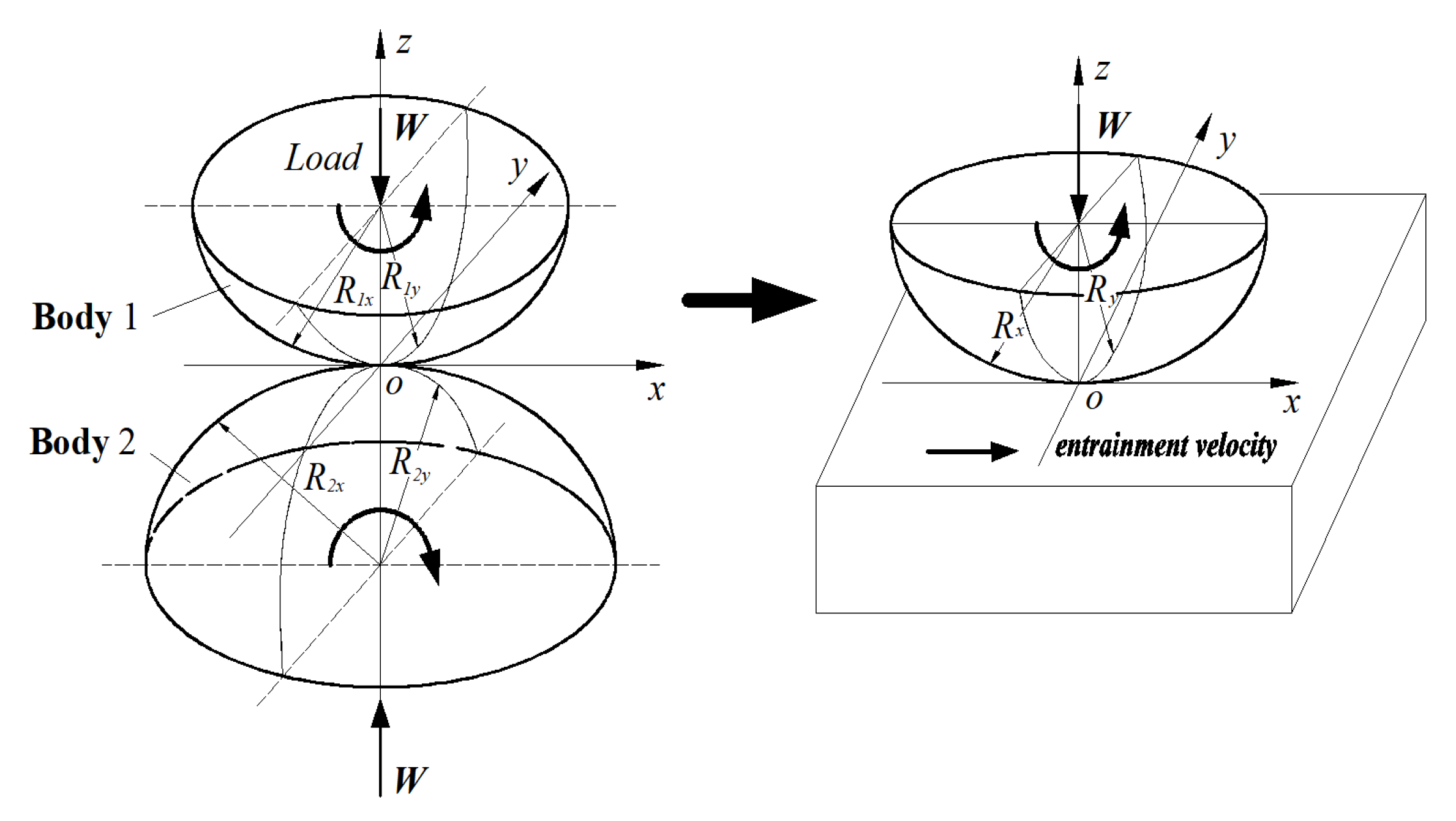
2.2.1. Hertz Contact Formula

The Hertz contact theory is the basis for the calculating the maximum contact stress of the VH-CATT cylindrical gear. The contact stress equations of VH-CATT cylindrical gear are derived by the Hertz theory of classical contact mechanics and gear meshing theory.
σ H = F n ( 1 ρ 1 ± 1 ρ 2 ) π [ ( 1 μ 1 2 E 1 + 1 μ 2 2 E 2 ) ] L
where the μ 1 and μ 2 are the poisson’s ratios of pinion and gear, E 1 and E 2 are the elastic modulus of pinion and gear, F n is the normal force acting on the gear pairs, ρ 1 and ρ 2 are the curvature radius of pinion and gear, L is the total carrying length. To calculate the contact stress σ H of tooth surface of VH-CATT cylindrical gear, the normal force F n , total load length L and the synthetical curvature radius ρ must be modified through analysis and design formula.

2.2.2. Normal Force

The instantaneous contact line of VH-CATT cylindrical gear is the circular arc curve under the load. As shown in Figure 3, the slope of different location of circular arc curve is different, so the spiral angle of different location of circular arc curve is also different. Therefore, according to the principle of differential and integral calculus, mathematical statistical method, the spiral angle of VH-CATT cylindrical gear can be obtained.
As shown in Figure 3, the spiral angle of pitch circle cylindrical surface at the arbitrary point can be expressed as following.
β x = arcsin ( y / R T )
According to the equipartition theorem, the average of spiral angle can be given as following.
β m = 2 0 B / 2 arcsin y R T d y B   = arcsin B 2 R T + 2 R T B ( 1 ( B 2 R T ) 2 1 )
where the B is the tooth width. R T is the cutter head radius. According to the Equations (3) and (4), the normal force of VH-CATT cylindrical gear can be obtained as following.
F n = F t cos α t cos β m = 2 K H T 1 d 1 cos α n cos β m
where the F t is the tangential force acting on the gear pairs; T 1 is the torque applied to the gear pairs; d 1 is the diameter of the pitch circle of the pinion; K H is load coefficient; α t is the tangential pressure angle of the gear; α n is the normal pressure angle of the gear.

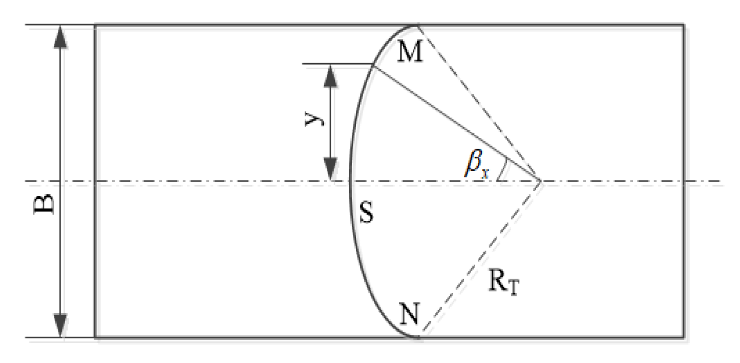
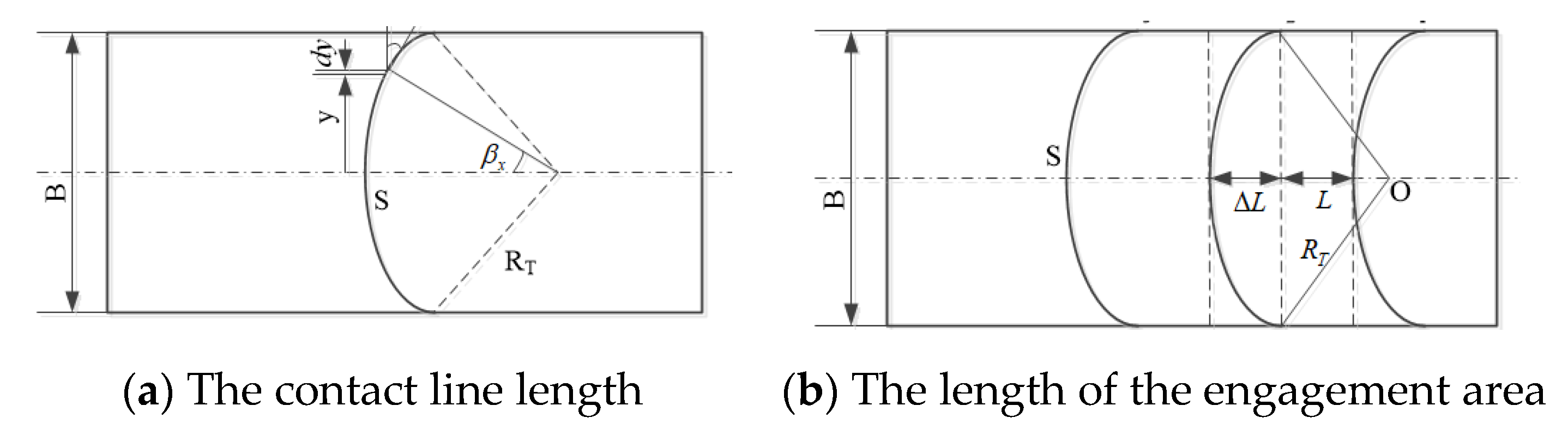
2.2.3. Total Carrying Length

The total carrying length L is connected with the tooth width, spiral angle of the base circle and contact ratio in the meshing process. The total carrying length is constantly changing at the different meshing position. And there are at least two or more teeth in meshing at the same time. Based on the differential thought, the VH-CATT cylindrical gear can be divided into several infinitesimal gear along the cylindrical arc line direction. Every infinitesimal gear can approximate be considered as the helical gear. As shown in Figure 4, the contact line length Δ S of infinitesimal gear can be obtained according to the calculation method of contact line length of helical gear, which is given as following.
Δ S = ε α d y cos β x
So, the total length of contact line of VH-CATT cylindrical gear can be given as following.
S = B / 2 B / 2 ε α d y cos β x = 2 0 B / 2 R T ε α R T 2 y 2 d y = 2 R T ε α arcsin B 2 R T ,
where the ε α is the transverse contact ratio of micro helical gear, which is also the transverse contact ratio of VH-CATT cylindrical gear. β x is the spiral angle of any micro helical gear on the plane of action.
The length Δ L + L of engagement area of VH-CATT cylindrical gear is shown as in Figure 4b.
The total contact ratio of VH-CATT cylindrical gear is given as following.
ε = L + Δ L p b t = ε α + ε β ,
where the ε is total contact ratio. ε β is the axial contact ratio of VH-CATT cylindrical gear and p b t is the axial pitch. The ε α and ε β are given as following.
ε α = L p b t = d a 1 2 d b 1 2 + d a 2 2 d b 2 2 2 a sin α t 2 π m t cos α t
ε β = Δ L p b t = cos β m π m n cos α t [ R T R T 2 ( B / 2 ) 2 ]
Based on the transverse contact ratio and the axial contact ratio, the coincidence coefficient Z ε is given as following.
Z ε = 4 ε α 4 ( 1 ε β ) + ε β ε α
where the d a 1 and d a 2 are the addendum circle diameter of pinion and gear. d b 1 and d b 2 are the basis circle diameter of pinion and gear. The a is the center distance. The α t is the meshing angle of gear end-face. α t is the pressure angle of gear end-face. Equation (10) reveals that the parameter R T 0.5 B . Although increasing the tooth width and decreasing the cutter diameter are beneficial to the increasing of axial contact ratio. The B and R T can’t be arbitrarily changed. The parameter R T is usually set as R T 1.5 B .
Using the coincidence coefficient Z ε , the length of contact line of VH-CATT cylindrical gear is modified. So, the total carrying length L can be obtained as following.
L = S Z ε 2 = 2 R T ε α arcsin B 2 R T Z ε 2

2.2.4. Synthetical Curvature Radius

With the changing of meshing point of the tooth profile, the curvature radius of tooth surface is also changing, and the synthetic curvature radius and the contact stress are also changing at the different meshing point. Based on the Hertz contact theory, the contact problem of VH-CATT cylindrical gear can be simplified to the elliptical equivalent contact model, which is shown as in Figure 5. The contact surfaces of pinion and gear coincide on the x y plane.
The two principal plane is choosed as the direction of x and y coordinate axis. R 1 x and R 2 x are the main curvature radius of pinion and gear at the meshing point in the x z plane. The equivalent curvature radius R x in the x z plane is the synthetical curvature radius of VH-CATT cylindrical gear in the direction of tooth profile. R 1 y and R 2 y are the main curvature radius of pinion and gear at the meshing point in the y z plane. The equivalent curvature radius R y in the y z plane is the synthetical curvature radius of VH-CATT cylindrical gear in the direction of tooth trace.
R x = R 1 x R 2 x R 1 x + R 2 x = 1 K 2 I + K 2 I I
R y = R 1 y R 2 y R 1 y + R 2 y = 1 K 1 I + K 1 I I
So the calculation formula of synthetic curvature radius of VH-CATT cylindrical gear can be derived according to the space meshing principle and tooth surface equation, which is given as following.
R = R x R y R x + R y = 1 K 1 I + K 1 I I + K 2 I + K 2 I I ,
where the K 1 and K 2 are the main curvature radius of convex tooth surface , K 1 and K 2 are the main curvature radius of concave tooth surface .
ρ = ρ 1 ρ 2 ρ 1 + ρ 2 = R
where the ρ 1 is the curvature radius of pinion. ρ 2 is the curvature radius of gear. ρ is the synthetical curvature radius. When the normal force F n , total load length L and synthetical curvature radius ρ are determined, the computing formula of contact fatigue strength of VH-CATT cylindrical gear can be obtained as following.
σ H = F n ( 1 ρ 1 ± 1 ρ 2 ) π [ ( 1 μ 1 2 E 1 + 1 μ 2 2 E 2 ) ] L = Z E Z ε Z β K H T 1 ( K 1 I + K 1 I I + K 2 I + K 2 I I ) R T d 1 ε α cos α n cos β arcsin B 2 R T
Because of the special contact types of VH-CATT cylindrical gear, the formula of contact stress needs correction coefficients to amend, such as the plastic coefficient Z E , helix angle coefficient Z β and load coefficient K H .

3. Results

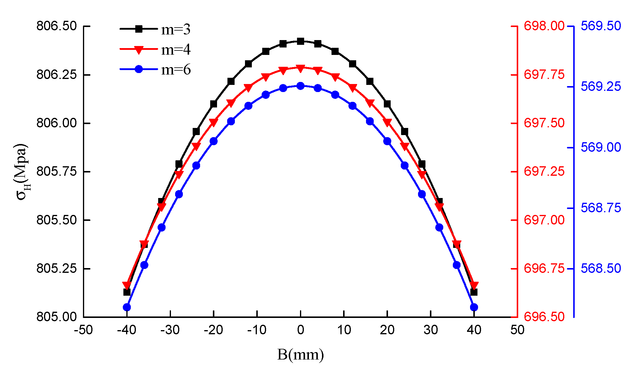
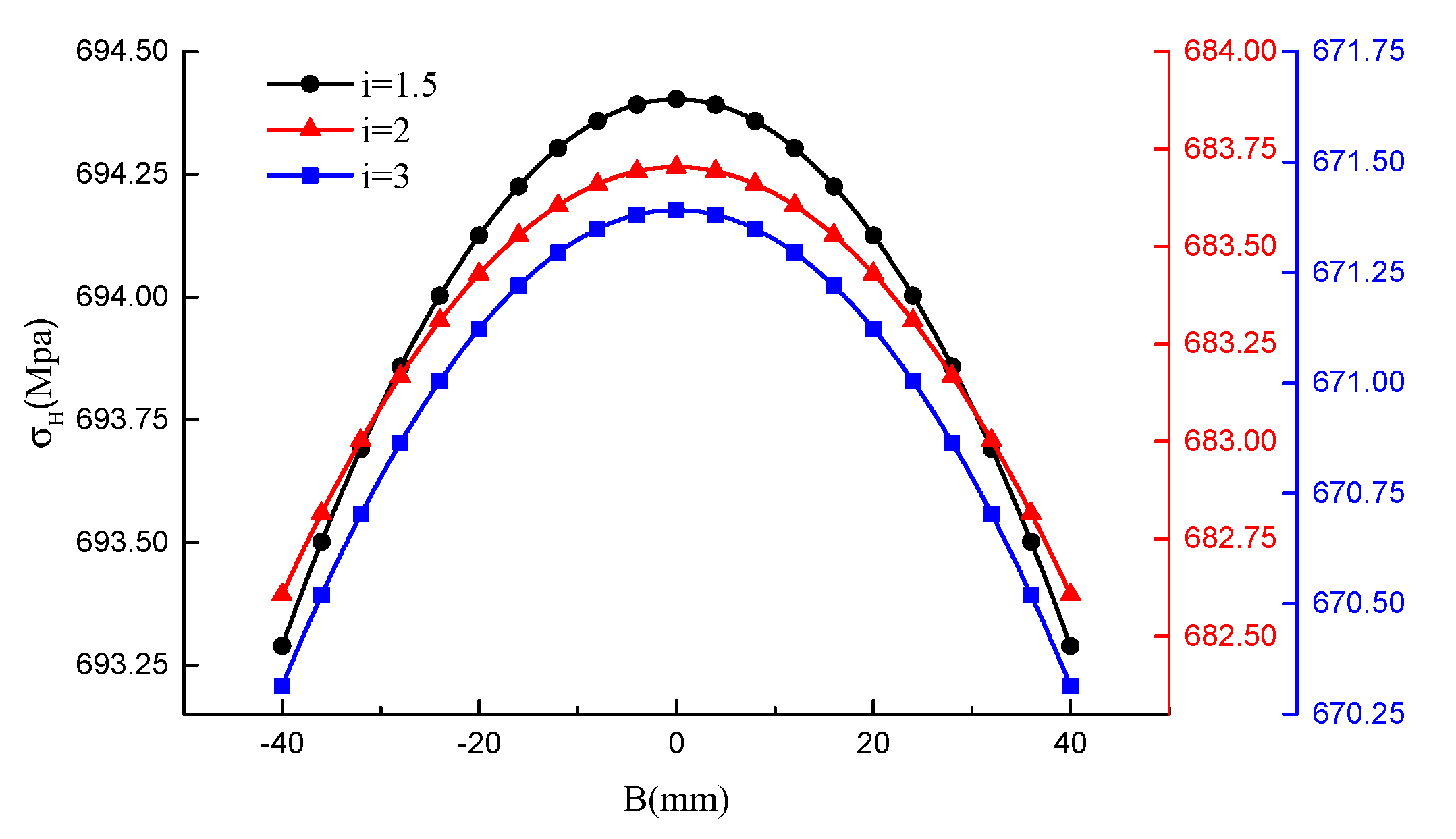
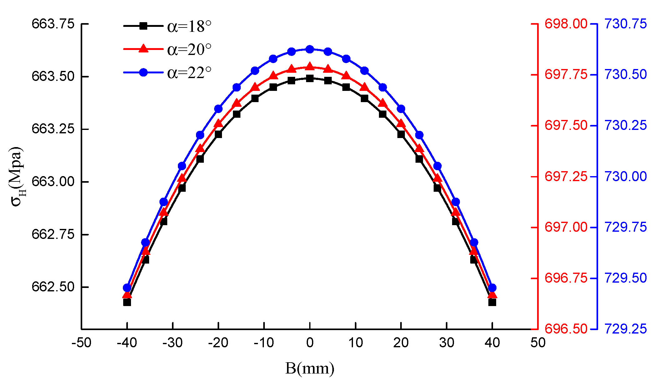
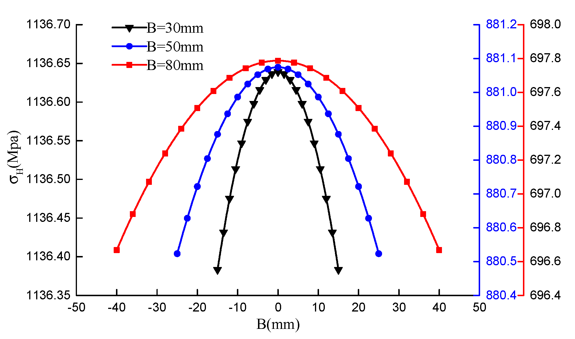
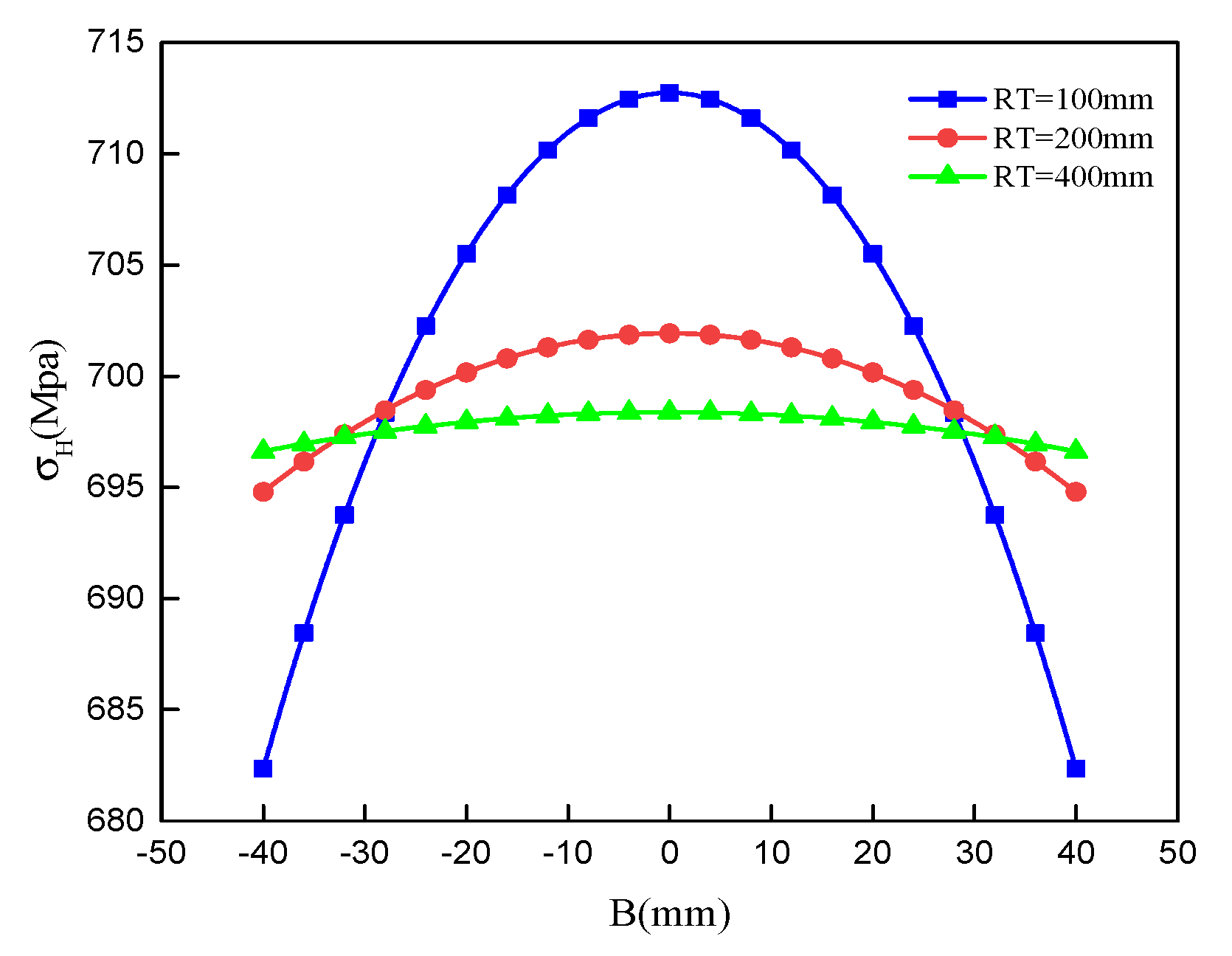
3.1. Analysis of Contact Stress

Based on Equation (17), the calculating parameter for contact stress of VH-CATT cylindrical gear are given as Table 1, and the load parameter is given as 191 N m . The contact stress of the VH-CATT cylindrical gear can be calculated according to the equation. From Equation (17), we can see that the characteristic parameters effecting contact stress are the modulus, transmission ratio, pressure angle, tooth width and cutter head radius. The impact of modulus, transmission ratio, pressure angle, tooth width, and cutter head radius on the distribution laws of contact stress of VH-CATT cylindrical gear will be discussed in the next subsections.
Figure 6 shows the effect of modulus on the distribution of contact stress in the tooth width direction. It could be seen from Figure 6 that the distribution of contact is close to the Hertz pressure distribution. It could be seen from Figure 6 that the contact stress reaches its maximum on the middle section and its minimum on the two sides in the tooth width direction. The contact stress presented a symmetric distribution along tooth width direction. The maximal contact stress decreases and the pressure tends to flatten with increase of modulus. This shows that increasing modulus can improve the contact strength of VH-CATT cylindrical gear.
Figure 7 shows the effect of transmission ratio on the distribution of contact stress in the tooth width direction. Where, the i is transmission ratio of the two gears, that is, the ratio of the number of teeth of the gear to that of the pinion. It can be seen in Figure 7 that the contact stress reaches its maximum on the middle section and its minimum on the two sides in the tooth width direction. The contact stress tends to decrease symmetrically along tooth width direction to the gear end-face. The maximal contact stress decreases and the pressure tends to flatten with increase of transmission ratio. This shows that the contact strength of VH-CATT cylindrical gear can be improved by selecting a larger transmission ratio.
Figure 8 shows the effect of pressure angle on the distribution of contact stress in the tooth width direction. It could be seen from Figure 8 that the contact stress reaches its maximum on the middle section and its minimum on the two sides in the tooth width direction. The contact stress tends to decrease symmetrically along tooth width direction to the gear end-face. The maximal contact stress increases with the increase of pressure angle. This shows that the contact strength of VH-CATT cylindrical gear will be reduced if a larger pressure angle is selected.
Figure 9 shows the effect of tooth width on the distribution of contact stress in the tooth width direction. It could be seen from Figure 9 that the contact stress reaches its maximum on the middle section and its minimum on the two sides in the tooth width direction. The contact stress tends to decrease symmetrically along tooth width direction to the gear end-face. The maximal contact stress increases with increase of tooth width. It shows that the contact strength of VH-CATT cylindrical gear can be improved and the length of contact line can be further increased with increase of tooth width.
Figure 10 shows the effect of cutter head radius on the distribution of contact stress in the tooth width direction. It could be seen from Figure 10 that the contact stress reaches its maximum on the middle section and its minimum on the two sides in the tooth width direction. The contact stress tends to decrease symmetrically along tooth width direction to the gear end-face. The maximal contact stress decreases with increase of cutter head radius. With the increase of cutter radius, the arc tooth trace of VH-CATT cylindrical gear gradually approaches to a straight line, and the contact stress distribution is closer to the constant value. The cutter head radius should not be too small, because it is too small, which will lead to a large stress peak value. Therefore, the dangerous section of VH-CATT cylindrical gear is the mid-section. The cutter head radius should not be too large, because too large it will cause arcuate tooth trace to approach the spur gear, making the length of the contact line in the meshing process shorter, thus reducing the bearing capacity of the VH-CATT cylindrical gear. Therefore, when designing and using VH-CATT cylindrical gear, it is necessary to choose the appropriate cutter head radius.

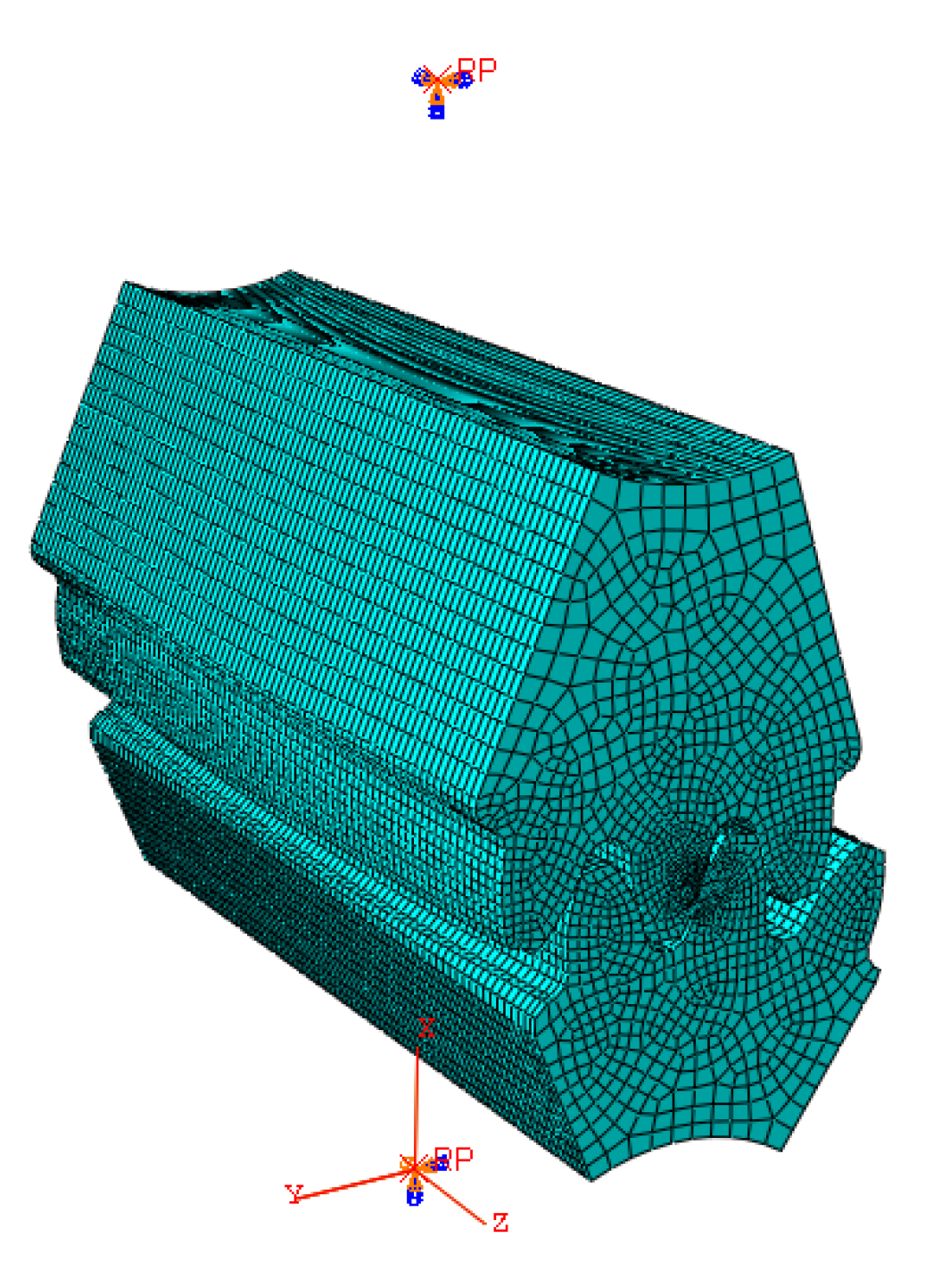
3.2. Finite Element Analysis

Finite Element Analysis (FEA) has become a common tool for predicting contact stress, load sharing, and bending stress distributions of gear drives. Several researchers have examined the contact and bending stresses in various types of gears using commercial FEA codes. Different meshing conditions can be conveniently established in a FEA model, which is widely used to calculate stress and strain of various types of gear pairs. More accurate results can be obtained, and the computational time can be saved by optimizing boundary conditions, grids and nodes. By solving FEA models, the geometric parameters and frictional forces of different gear pairs can be calculated quantitatively.
In the meshing process of the VH-CATT cylindrical gear, the curvature radii R x and R y of the meshing point at any time can be calculated, and the corresponding contact stress can be calculated by the formula derived in this paper. The revolutions per minute (RPM) and torque selected in this analysis are just an example to illustrate the change trend of contact stress on the tooth surface of cylindrical gear with variable hyperbolic arc profile and verify the correctness of the calculation by FEA. In order to obtain a grid that satisfies the contact analysis, a linear reduced integration cell is selected considering the efficiency and accuracy of the analytical calculations (C3D8R). The element mesh model and boundary conditions are shown in Figure 11. A reference point is established at the center of the gear. The gear establishes Multi-point constraints (MPC) constraints with the two reference points, and the boundary conditions and constraints are imposed on the on the reference point. A fixed constraint is applied at the reference point of the driving wheel, with only one degree of freedom of rotation along the driving wheel, and a bending moment is applied at that point; at the driven wheel, the reference point applie a full fixation constraint. The contact surfaces of the gears are set to contact pairs. The static universal solution is used.
In order to verify the correctness of the calculating formula of contact fatigue strength of VH-CATT cylindrical gear. The FEA is used to calculate and analyze its contact stress and contact form. Based on the gear parameters in Table 1, the FEA model of VH-CATT cylindrical gear pair is carried out in Abaqus. It can be seen in Figure 12 that the contact stress at the middle section is the largest, and it is distributed symmetrically along the tooth width in a decreasing trend to both ends. Analysis showed that the contact stress is elliptically distributed on the tooth surface, which is consistent with the ideal ellipse in the contact area of VH-CATT cylindrical gear. The maximum compressive stress occurs at the center of the contact ellipse, and the compressive stress on the convex surface is larger than that on the concave surface for a pair of contact surfaces. As shown in Figure 12a, the maximum contact stress of the convex surface is 625.3 Mpa. As shown in Figure 12b, the maximum contact stress of concave surface is 758.0 Mpa, and the average maximum stress of pinion and gear is 691.65 Mpa.
Based on Equation (17), the theoretical value of contact stress at the mid-section is calculated, which is 697.7871 Mpa. By contrast with the theoretical calculated value and the mean value of FEA, its error is only 0.8873%. This shows that the derived formula of contact fatigue strength of VH-CATT cylindrical gear in this paper has high accuracy and can accurately reflect the real contact stress value of tooth surface, which is suitable for the design and check calculation of gear.

4. Conclusions

The VH-CATT cylindrical gear is a kind of gear transmission and the computing formula of contact stress of VH-CATT cylindrical gear is derived in this paper according to Hertz formula. The effects of the module, transmission ratio, pressure angle, tooth width, and cutter head radius for the contact stress of the VH-CATT cylindrical gear along the tooth width direction were investigated. The results showed that the contact stress presented a symmetric distribution along the tooth width direction to the gear’s end-face. The maximal contact stress decreased with an increase of the modulus, transmission ratio, and cutter head radius. The maximal contact stress increased with the increase of the pressure angle and tooth width. So, the contact strength and service life of the VH-CATT cylindrical gear can be improved by selecting appropriate parameters. Moreover, a FEA was carried out to verify the correctness of the theoretical computing formula of the contact stress of the VH-CATT cylindrical gear. The stress value of FEA was in accordance with the theoretical calculated value by the formula. It indicates that the derived formula of the contact fatigue strength of the VH-CATT cylindrical gear has high accuracy and can accurately reflect the real contact stress value of the tooth surface. In this paper, the checking formula, analysis method, and results can provide references for the design and check of this kind of gear transmission.

Author Contributions

Conceptualization, Y.W.; methodology, Y.W., R.G., Y.L. and C.D.; software, Y.W., R.G. and D.L.; validation, Y.W. and R.G.; formal analysis, Y.W. and R.G.; investigation, Y.W., Y.L. and G.Z.; resources, R.G.; data curation, Y.W. and A.W.; writing—original draft preparation, Y.W., R.G. All authors have read and agreed to the published version of the manuscript.

Funding

This research was supported by Gansu Provincial Natural Science Foundation of China (Grant No. 18JR3RA140), The Open Fund of Hubei Key Laboratory of Mechanical Transmission and Manufacturing Engineering at Wuhan University of Science and Technology (Grant No. MTMEOF2019B02), and the Hongliu Youth Fund of Lanzhou University of Technology (Grant No.07-062005).

Conflicts of Interest

The authors declare no conflict of interest.

References

  1. Mo, S.; Zhang, T. Analytical Investigation on Load Sharing Characteristics of Herringbone Planetary Gear Train with Flexible Support and Floating Sun Gear. Mech. Mach. Theory 2020, 144, 1–27. [Google Scholar]
  2. Lingli, C.; Tongtong, L.; Jinfeng, H.; Huaqing, W. Improvement on Meshing Stiffness Algorithms of Gear with Peeling. Symmetry 2019, 11, 1–13. [Google Scholar]
  3. Qin, D. Review of research on international gear transmissions. J. Chongqing Univ. 2014, 8, 1–10. [Google Scholar]
  4. Xiao, H.; Hou, L.; Dong, L.; Jiang, Y.; Wei, Y. Mathematical Modeling of Rotary Cutter Arc Tooth Line of Cylindrical Gear Shaped by Origin Face of Rotary Cutter. J. Sichuan Univ. Eng. Sci. Ed. 2013, 45, 171–175. [Google Scholar]
  5. Wang, S.; Hou, L.; Dong, L.; Xiao, H. Modeling and strength analysis of cylindrical gears with curvilinear shape teeth for manufacture. J. Sichuan Univ. Eng. Sci. Ed. 2012, 2, 210–215. [Google Scholar]
  6. Tang, R.; Hou, L.; Zhou, B. Modelling and strength analysis for manufacture-oriented cylindrical gear with arcuate tooth trace. Aust. J. Mech. Eng. 2016, 26, 1–8. [Google Scholar] [CrossRef]
  7. Qi, Z.; Rui, T.; Guang, W. Method of processing and analysis of meshing and contact of circular-arc-tooth-trace cylindrical gears. Trans. FAMENA 2016, 40, 11–25. [Google Scholar]
  8. Wei, Y.; Ma, D.; Wu, Y.; Luo, L.; Bai, Q.; Hou, L. Study on the tooth surface and curvature characteristics of cylindrical gear with variable hyperbolic arc-tooth-trace. Adv. Eng. Sci. 2017, 49, 196–203. [Google Scholar]
  9. Luo, L.; Hou, L.; Zhao, F.; Wu, Y.; Bai, Q. Analysis on geometric characteristics of cylindrical gear with variable hyperbolic circular-arc-tooth-trace. Adv. Eng. Sci. 2018, 50, 17–179. [Google Scholar]
  10. Wei, Y.; Yang, S.; Zhang, Q.; Wang, Y.; Hou, L. Numerical Analysis for Isothermal Elastohydrodynamic Lubrication of Cylindrical Gears with Variable Hyperbolic Circular-Arc-Tooth-Trace. Trans. FAMENA 2018, 42, 61–72. [Google Scholar]
  11. Wei, Y.-Q.; Ma, D.-Q.; Liu, Y.-P.; Hou, L. Research on Thermal Elastohydrodynamic Lubrication of Cylindrical Gears with Curvilinear Shaped Teeth. J. Chin. Soc. Mech. Eng. 2018, 39, 451–458. [Google Scholar]
  12. Tseng, R.-T.; Tsay, C.-B. Mathematical model and undercutting of cylindrical gears with curvilinear shaped teeth. Mech. Mach. Theory 2001, 36, 1189–1202. [Google Scholar] [CrossRef]
  13. Ma, Z.; Deng, C. CNC machining method of whole modified surface of cylindrical gears with arcuate tooth trace. J. Mech. Eng. 2012, 48, 165–171. [Google Scholar] [CrossRef]
  14. Zhao, F.; Hou, L.; Duan, Y. Research on the forming theory analysis and digital model of circular arc gear shaped by rotary cutter. J. Sichuan Univ. Eng. Sci. Ed. 2016, 48, 119–125. (In Chinese) [Google Scholar]
  15. Litvin, F.L.; Tsay, C.B. Helical gears with circular arc teeth: Simulation of conditions of meshing and bearing contact. ASME J. Mech. Transm. Autom. Des. 1985, 107, 556–564. [Google Scholar] [CrossRef] [Green Version]
  16. Ru, Y.W. Analysis on Contact Stress after Gear Meshing and Finite Element of Stiffness. Appl. Mech. Mater. 2015, 3752, 670–675. [Google Scholar]
  17. Morrish, K.; Ajay, S.R.; Amalendu, B. Stress Analysis of an Asymmetric Spur Gear Tooth with Series of Circular Hole using Finite Element Method. J. Innov. Mech. Eng. 2018, 1, 21–25. [Google Scholar]
  18. Litvin, F.L.; Fuentes, A.; Hayasaka, K. Design, manufacture, stress analysis, and experimental tests of low-noise high endurance spiral bevel gear. Mech. Mach. Theory 2006, 41, 83–118. [Google Scholar] [CrossRef]
  19. Parsons, B.N.; Walton, D.; Andrei, L.; Andrei, G. Non-standard cylindrical gears. Gear Technol. 2004, 21, 30–37. [Google Scholar]
  20. Fuentes, A.; Ruiz-Orzaez, R.; Gonzalez-Perez, I. Computerized design, simulation of meshing, and finite element analysis of two types of geometry of curvilinear cylindrical gears. Comput. Methods Appl. Mech. Eng. 2014, 272, 321–339. [Google Scholar] [CrossRef]
  21. Shuai, M.; Zhongxiang, Y. Analytical investigation on load-sharing characteristics for multi-power face gear split flow system. J. Mech. Eng. Sci. 2020, 234, 676–692. [Google Scholar]
  22. Sun, Z.; Hou, L.; Wang, J. Contact strength analysis of ciucular-arc-tooth-trace cylindrical gear. J. Braz. Soc. Mech. Sci. Eng. 2016, 38, 999–1005. [Google Scholar]
Figure 1. Machining principle coordinate system with great cutter head.
Symmetry 12 01318 g001
Figure 2. Modeling of VH-CATT cylindrical gear
Symmetry 12 01318 g002
Figure 3. The circular arc tooth line of extended surface of VH-CATT cylindrical gear.
Symmetry 12 01318 g003
Figure 4. The extended surface of the VH-CATT cylindrical gear.
Symmetry 12 01318 g004
Figure 5. The elliptical equivalent contact model.
Symmetry 12 01318 g005
Figure 6. The distribution law of contact stress under the different modulus.
Symmetry 12 01318 g006
Figure 7. The distribution law of contact stress under the different transmission ratio.
Symmetry 12 01318 g007
Figure 8. The distribution law of contact stress under the different pressure angle.
Symmetry 12 01318 g008
Figure 9. The distribution law of contact stress under the different tooth width.
Symmetry 12 01318 g009
Figure 10. The distribution law of contact stress under the different cutter head radius.
Symmetry 12 01318 g010
Figure 11. Element mesh model and Setting of boundary conditions.
Symmetry 12 01318 g011
Figure 12. The contact stress by the Finite Element Analysis (FEA).
Symmetry 12 01318 g012
Table 1. Design and analysis parameters of the Cylindrical Gear with Variable Hyperbolic Circular-Arc-Tooth-Trace (VH-CATT) cylindrical gear.
ParametersPinionGear
Number of teeth2129
Modulus (mm)44
Pressure angle (degree)2020
Tooth width (mm)8080
Cutter radius (mm)500500
Poisson ratio0.30.3
Elasticity modulus (GPa)206206

