Article

Symmetry-Breaking for Airflow Control Optimization of an Oscillating-Water-Column System

Department of Automatic Control and Systems Engineering, Faculty of Engineering of Bilbao, Automatic Control Group (ACG), Institute of Research and Development of Processes (IIDP), University of the Basque Country (UPV/EHU), Po Rafael Moreno no3, 48013 Bilbao, Spain
*
Author to whom correspondence should be addressed.
Symmetry 2020, 12(6), 895; https://doi.org/10.3390/sym12060895
Submission received: 21 April 2020 / Revised: 5 May 2020 / Accepted: 9 May 2020 / Published: 1 June 2020
(This article belongs to the Special Issue Symmetry in Nonlinear Studies)

Abstract

:
Global optimization problems are mostly solved using search methods. Therefore, decreasing the search space can increase the efficiency of their solving. A widely exploited technique to reduce the search space is symmetry-breaking, which helps impose constraints on breaking existing symmetries. The present article deals with the airflow control optimization problem in an oscillating-water-column using the Particle Swarm Optimization (PSO). In an effort to ameliorate the efficiency of the PSO search, a symmetry-breaking technique has been implemented. The results of optimization showed that shrinking the search space helped to reduce the search time and ameliorate the efficiency of the PSO algorithm.

1. Introduction

Natural resources are the best alternative to limited fossil fuel for the European energy market, especially that EU countries consume one-fifth of the global oil and gas supplies. This leads to the annual purchase of 350 billion Euros worth of petroleum and gas products from other countries [1]. Nowadays, an upward trend to develop renewable energy projects in European countries has been at the forefront of European policies in order to reduce fossil fuel consumption [2]. The conclusion of the Conference of Parties (COP21) has put in place further motivated goals for a 2 C decrease [3], hence the need for Renewables to take a big part in the future of energy systems and markets. This calls for the importance of a stable and reliable energy mix development based on all renewable resources [4]. In fact, renewable energy sources are estimated to have provided 33% of total power generation in the UK and 40% in Germany and Spain in 2018 [5].
Even though Ocean energy is more reliable, predictable, and denser than other Renewables, Marine Renewable Energy (MRE) still remains underdeveloped and the least tapped energy industry [6]. The majority of MRE-based industries are up to the present time in the early-phase of development varying between theory and design, until the demonstration phase [1]. Although decades of research and development were invested, a mere 529 MW of MRE capacity has been recorded as operational at the end of 2017 and more than 93% of them are summarized in two main facilities [7]: Sihwa plant in South Korea with 254 MW [8] and La Rance tidal power station in France with 240 MW [9]. The main obstacles hindering the development of MRE are geographical installation that can affect nearby coastal and fishing areas and maritime routes, required and existing electricity infrastructure, potential environmental impacts, and legal and regulatory framework [7].
Wave energy is one of the most exploited forms of ocean energy and Wave Energy Converters (WEC) have seen increasing growth in research and development during the last few decades [10]. In fact, the number of WEC prototypes has increased to almost one thousand inventions [10]. However, barely two hundred of these devices have achieved the phase of model testing [11]. The same as the rest of the MRE industry, the WEC industry is still suffering from a high cost in comparison with the traditional electricity generation [10]. Efforts were invested to improve the efficiency of WECs by studying and carrying out feasibility in different sites like in [12,13,14]. Another way was by increasing the attractiveness of WECs by integrating them in other maritime constructions like breakwater, pier, or jetty [15]. An example of WEC integrated with a breakwater is the NEREIDA Multiple Oscillating Water Column (MOWC) installed in the breakwater of Mutriku in Spain [16].
This paper discusses the airflow control of an OWC system based on Wells turbine for wave energy conversion. The main drawback of Power-Take Off (PTO) systems equipped with Wells turbine is the power-limitation due to the occurrence of the stall effect [17,18]. In this context, an airflow control, tuned using Particle Swarm Optimization (PSO), is suggested to govern the air-valve within the plant’s capture-chamber which can help regulate the airflow speed. To further enhance the effectiveness of the PSO algorithm, the Symmetry-breaking Constraints (SBC) were introduced to the problem by reducing the search space.
Symmetry is often used to analyze and simplify complex problems in physics [19] and chemistry [20]. Symmetry is also used for geometric and structural optimization [21,22], problem formulation [23], and control system design [24,25]. In recent years, symmetry has been used to aid optimization problems [26,27,28]. In optimization theory, symmetries are transformations of the decision space that do not change the cost or feasible region. In some problems, symmetry can enlarge the dimension of the search space. Therefore, symmetries have to be taken into account in order to reduce the search time by visiting symmetric solutions. Many techniques have been developed in constraint satisfaction problems to rule out symmetry either statically by the inclusion of SBCs [29,30,31] or dynamically by altering the search technique to evade symmetric states [32,33,34].
PID controller tuning is a delicate and complex task when lacking a systematic approach. To solve the problem design of PID controllers, the optimization theory has been proven to be an effective method to tune and optimize the controller parameters [35,36,37]. Numerous optimization algorithms were investigated and tested with the PID controller in different applications for instance the Particle Swarm Optimization (PSO) [38,39], the Water Cycle Algorithm (WCA) [36,39], and the Harmony Search Algorithm (HSA) [37,39]. The PSO Optimization algorithm is an evolutionary computation method developed by J. Kennedy and R.C. Eberhart since 1995 [40]. This sophisticated algorithm is inspired from the swarming behavior of biological populations like birds’ flocks and fish schools [40,41]. PSO has received increased attention in many research fields recently such as in electric power systems [42], in electromagnetic [43], in advanced information technology and networking [44] and many more.
The remainder of the article has been arranged as follows: Section 2 introduces the modelling section that describes all elements of the OWC system. Section 3 introduces the stalling behavior and the problem formulation of the proposed airflow control. Section 4 explains the use of Symmetry-breaking constraints (SBC) to help reduce the search space. Section 5 presents the PSO algorithm adopted to optimally tune the parameters the Proportional-Integral-Derivative (PID) controller’s parameters. Section 6 presents the test and simulations carried out to demonstrate the efficiency of the PSO algorithm with and without SBCs and then the performance of the proposed PSO-PID airflow control in extreme wave conditions versus the uncontrolled case. Finally, we finished the article with some concluding remarks in Section 7.

2. Model Statement

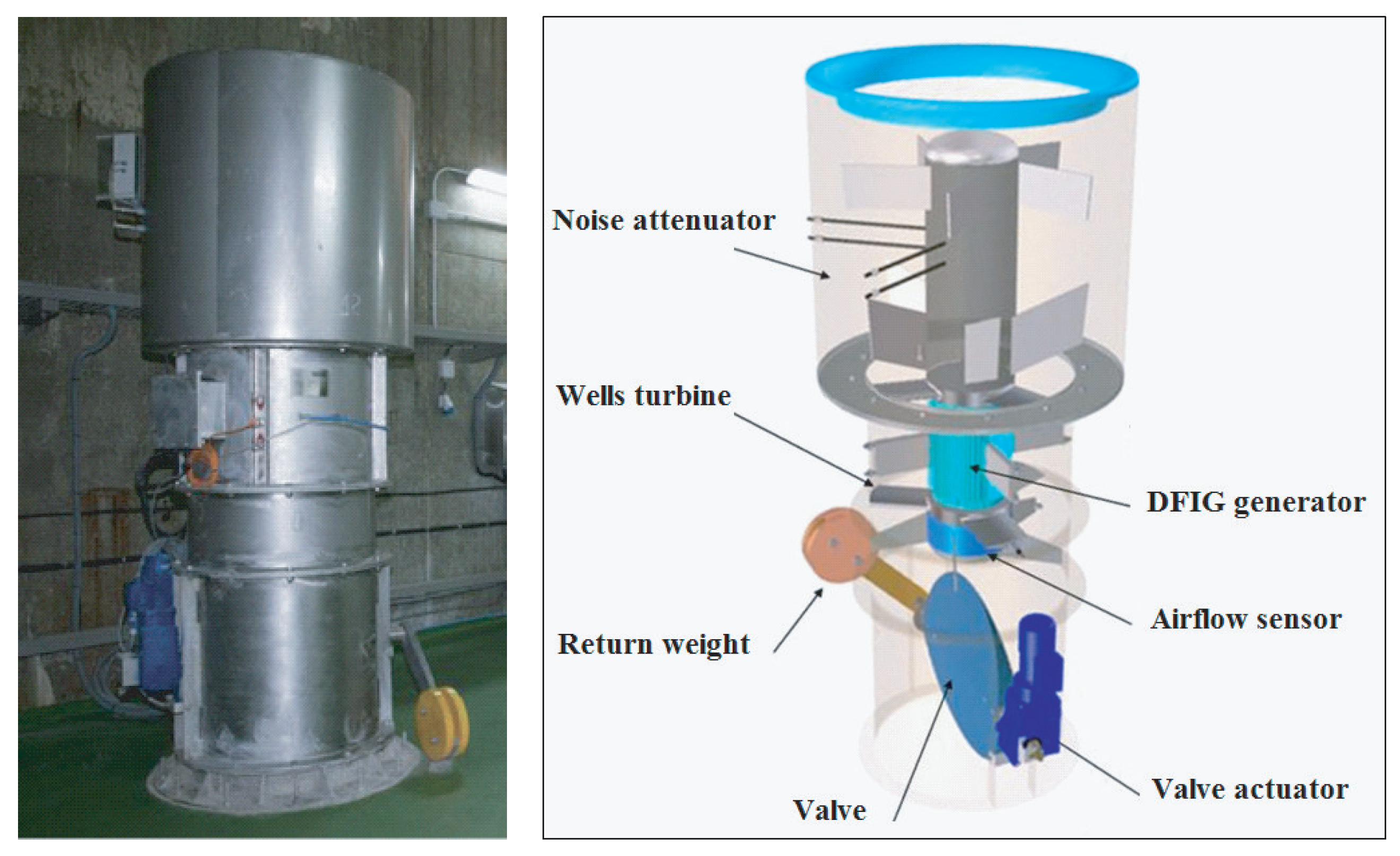
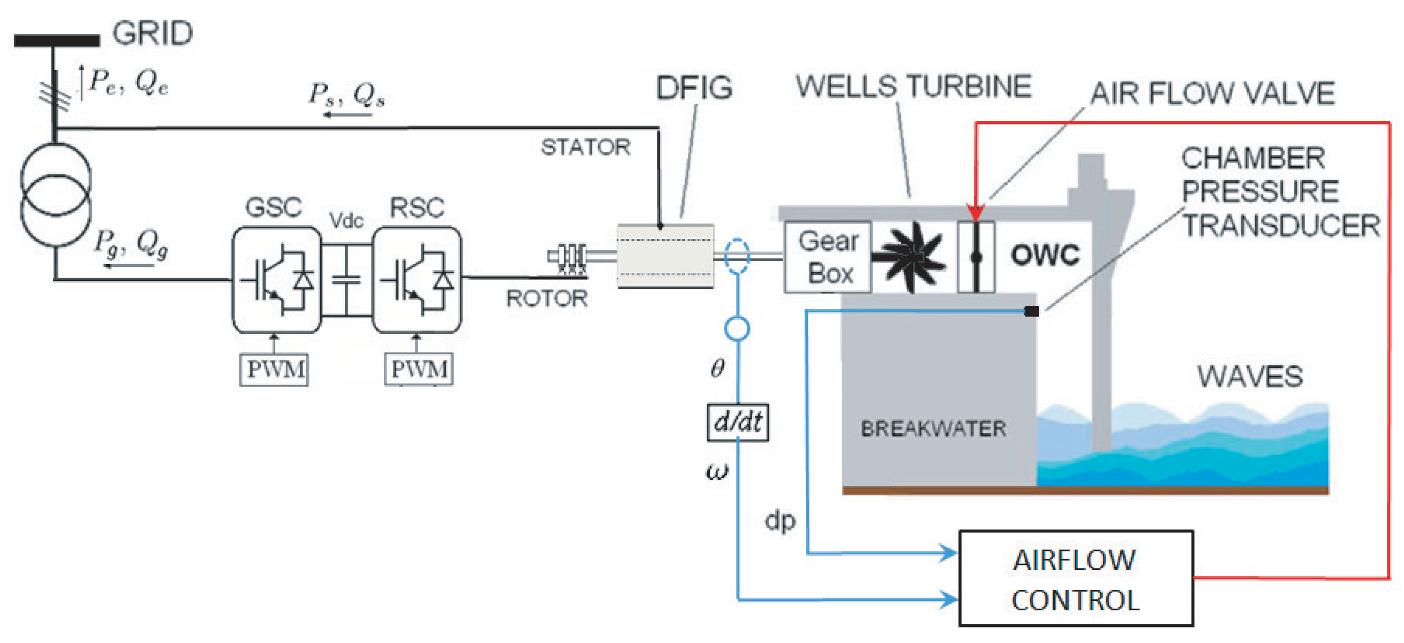
This section describes the modelling of the different subsystems of the Oscillating Water Column (OWC) shown in Figure 1, which would be including the mathematical models of the wave input, capture chamber, Wells turbine, and the Doubly Fed Induction Generator (DFIG).

2.1. Wave Surface Dynamics

A monochromatic unidirectional wave has been considered to be input into the implemented numerical model of the OWC system. There exist numerous wave theories in the literature to express the surface dynamics of ocean wave like the Cnoidal wave theory, second and higher-order Stokes theory and Airy linear theory [46,47]. In this paper, the Airy wave theory has been adopted because it presents the simplest description and it is the most widely used thanks to neglecting turbulence, friction losses, and other energy losses [47].
The parameters of a wave are detailed in Figure 1, with S W L represents the “Still-Water-Level”, h called “sea depth” represents the interval from the sea floor to S W L . H marks the interval from wave trough to wave crest called “wave height”. A measures the distance between S W L and the wave crest known as "wave amplitude" and λ represents the interval between successive crests known as “wavelength” [47,48]. Therefore, the surface elevation for a sea wave is given as [49,50]:
z ( x , t ) = A sin ω t k x θ = H / 2 sin ω t k x θ
where ω is the wave frequency, x is the wave horizontal coordinate, θ marks the the angular opening from the x-axis to waves’ direction, and k represents the wave number linked to ω with relation (2) as described in [49]:
k tanh ( k h ) = ω 2 / g
where g represents the acceleration gravity.

2.2. Capture Chamber Model

The volume of the air within the Oscillating Water Column’s chamber is defined in [38,48] as:
V ( t ) = V c + w c H k sin k l c / 2 sin ( ω t )
where V c , w c , and l c represent the chamber’s volume, inner width, and length, respectively.
The volume flow rate in the chamber can be obtained from Equation (3) and defined as [38,48]:
Q ( t ) = w c c H sin k l c 2 cos ( ω t )
with c = w / k .
Once the chamber’s geometry has been taken into account with Equation (4), the airflow velocity can be described as [38,48]:
v x ( t ) = Q ( t ) S = 8 A c w c π D 2 sin π l c c T w cos 2 π T w t
where T w is the wave period and D is the duct diameter.

2.3. Wells Turbine Model

The OWC is fitted with a Wells turbine, shown in Figure 2, is a self-rectifying axial-flow air turbine [50,51]. Self-rectifying air-turbines possess blades with special geometry allowing a unidirectional rotating motion regardless of the airflow direction [52,53,54].
The Wells turbine under study can be mathematically defined by Expressions (6)–(10) given in [18,55]:
d p = C a K 1 1 a a v x 2 + r ω r 2
K = ρ l b n / 2
T t = r C t K v x 2 + r ω r 2
ϕ = v x r ω r 1
Q = a v x
where d p represents the pressure drop, C a and C t represent the “power coefficients” and “torque coefficient”, ϕ stands for the “flow coefficient”, T t , K, and r represent the turbine’s torque, constant, and mean radius, l, b, and n represent the blade’s chord length, height, and number, ω r represents the “angular velocity”, a stands for the “cross-sectional area”, and ρ represents the air density.
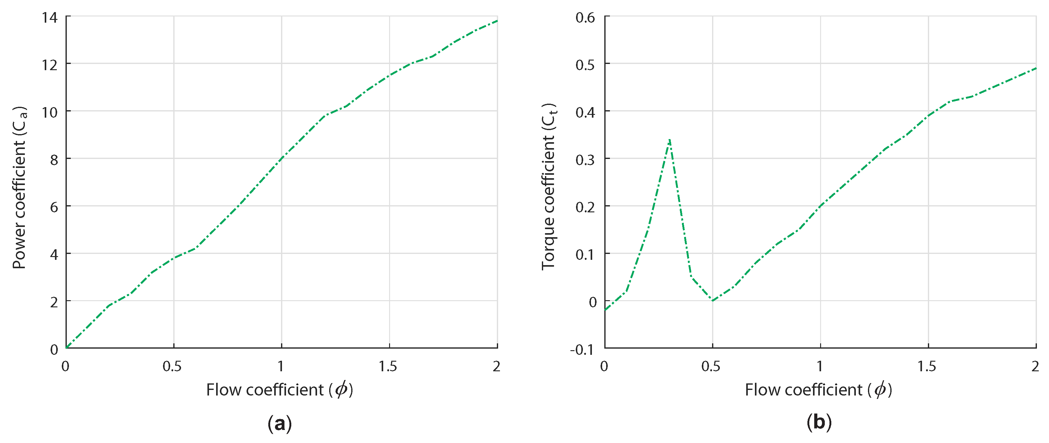
The characteristic curves of the Wells turbine under study are formed by the power coefficient C a and the torque coefficient C t versus the flow coefficient ϕ are shown in Figure 3.

2.4. Doubly Fed Induction Generator Model

In the OWC system under study, the Wells turbine drives a Doubly Fed Induction generator to deliver electrical power to the grid. In a d q diphase frame, the DFIG generator can be defined with the Expressions (11)–(16) given in [56,57]. Thus, the voltages of the stator and rotor in the d q frame can be defined as:
v d s = R s i d s + d ψ d s d t ω s ψ q s v q s = R s i q s + d ψ q s d t + ω s ψ d s
v d r = R r i d r + d ψ d r d t ω r ψ q r v q r = R r i q r + d ψ q r d t + ω r ψ d r
with R s , R r represent the stator and rotor resistances, ω s , ω r represent the stator and rotor angular velocity, i d s , i q s i d r and i q r represent the d-q stator and rotor currents.
The flux linkage at the stator and the rotor can be described by:
ψ d s = L s s i d s + L m i d r ψ q s = L s s i q s + L m i q r
ψ d r = L r r i d r + L m i d s ψ q r = L r r i q r + L m i q s
with L s s , L r r , and L m representing the stator, rotor, and magnetizing inductances, respectively.
The generated electromagnetic torque and its interaction with the turbine may be expressed as:
T e = 3 2 p ψ d s i q s ψ q s i d s
J p d ω r d t = T e T t
with p representing the pair pole number and J representing the inertia of the system.

3. Airflow Control Strategy

3.1. Stalling Behavior Problem

The stalling behavior in Wells turbines is a phenomenon which restricts the produced power. It happens in the event that the airflow speed v x rises; however, the rotational velocity ω r is slow because the generator is unable to spin quick enough to match the incoming airflow of strong waves. This behavior is visible in Figure 3b that demonstrates when the flow coefficient ϕ surpasses a critical value 0.3 . The torque coefficient C t declines considerably because the rotational speed ω r is unable to match the airflow velocity v x .
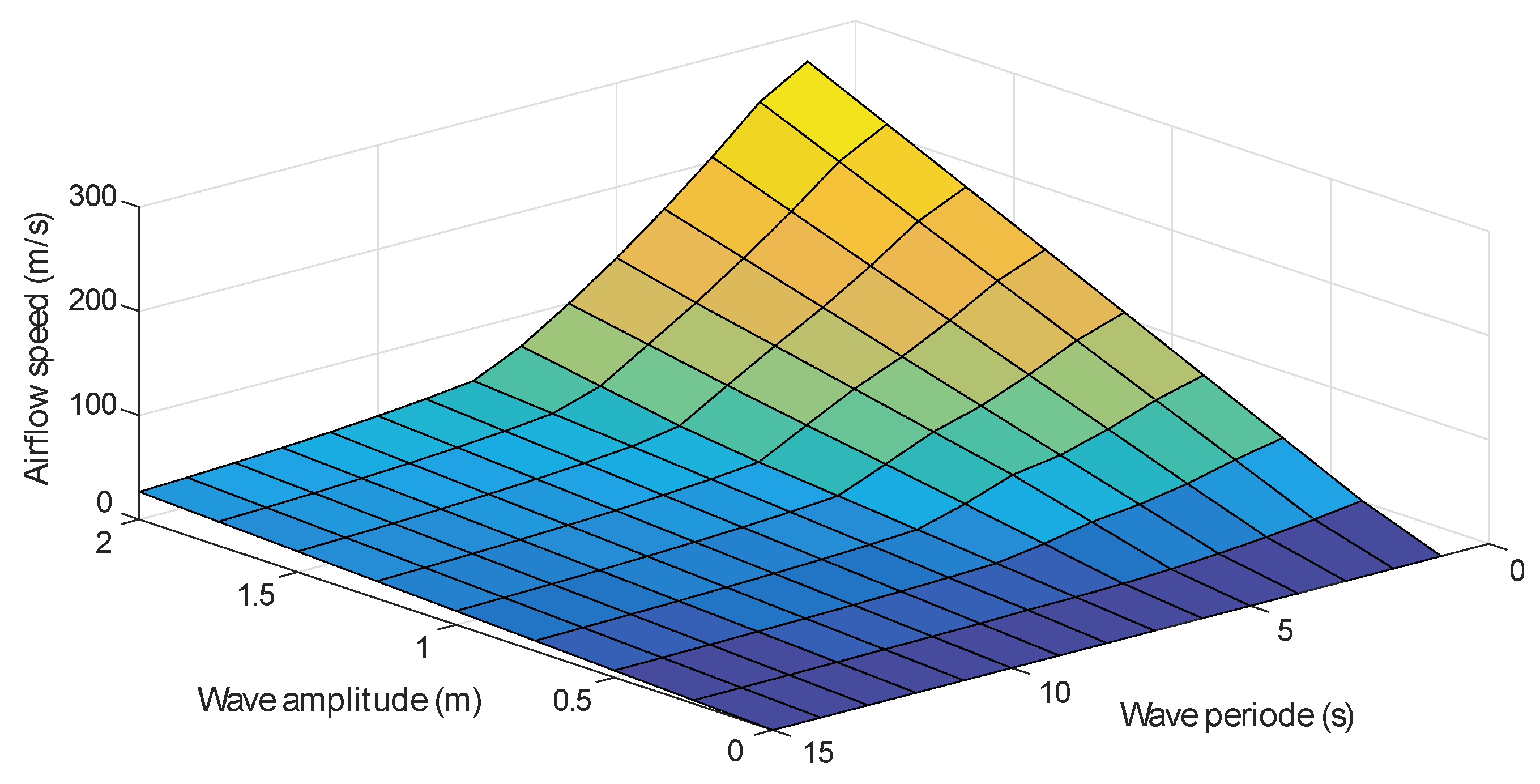
The flow coefficient ϕ defined in Section 2 (9) relies on the airflow velocity v x . In addition, as expressed in Section 2 (5), v x relies on both the wave amplitude and period. Indeed, the bigger the wave amplitude and the smaller the period are, the higher the pneumatic power and the airflow velocity are as shown in Figure 4.
The stall effect is demonstrated by investigating the uncontrolled OWC system with different sea states. The first sea condition is waves with a 10 s period and 0.9 m wave amplitude beginning at 0 s until 22.5 s. The second sea condition is waves with a 10 s period and a 1.2 m wave amplitude beginning at 22.5 s until 50 s. It may be observed in Figure 5 that during the first case the OWC offers a flow coefficient below the threshold value 0.3, but, during the second case, it surpasses 0.3.
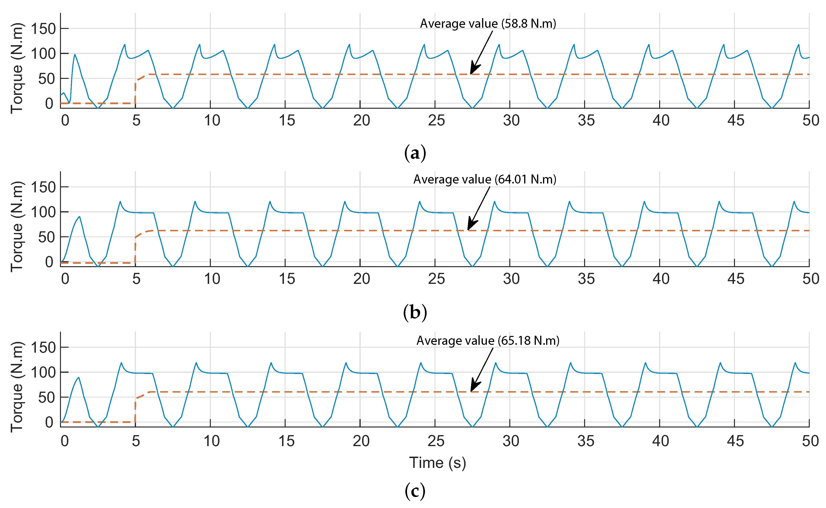
As a result, the attained turbine torque illustrated in Figure 6 shows no stalling during the first case and a significant decline at the crest of the second case because of the stall effect which reduces the obtained torque in terms of average value.
The Wells turbine’s stalling behavior can be evaded if the flow coefficient is constantly regulated [39,45]. From Expression (9), the flow coefficient relies on the airflow velocity in the turbine duct. Thus, adjusting the airflow speed v x will aid with evading the stall effect; therefore, an airflow control strategy has been suggested.
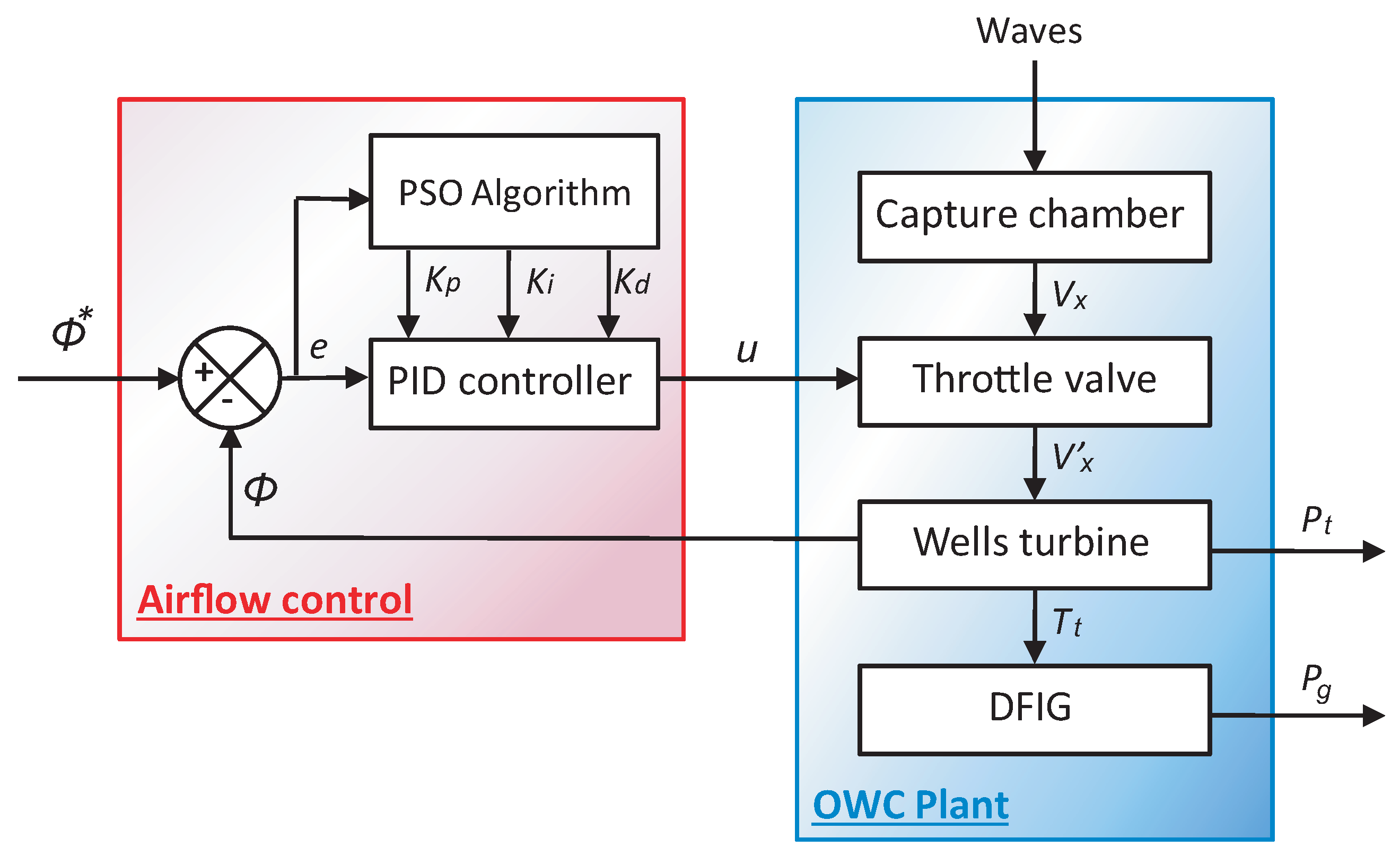
The implementation of the airflow control puts to use the air valve set within the capture chamber, and this device can be used to vary the pressure and airflow in the OWC system. The actuator of the air valve is controlled using a PID controller as explained by the scheme of Figure 7.
Tuning the PID controller in a complex system such as the OWC often is hard and tedious when using conventional methods and lacks an appropriate systematic design approach. In order to tune the PID controller, the use of optimization theory has been suggested as a promising recourse to easily calculate and optimize all PID gains [35,36,37].

3.2. Control Problem Formulation

The PID tuning optimization problem for the airflow control scheme’s objective is to compute the control design parameters x * = x 1 * , x 2 * , x 3 * T R 3 that represents the PID controller gains, i.e., x = K p , K i , K d T R + 3 . This is achieved while minimizing the cost function. The Integral of Absolute Error (IAE) has been adapted as the cost function for this problem [38,39]:
f I A E x = 0 + e x , t d t
with e . being the error between the reference and the controlled variable, as detailed in Figure 8.
The IAE cost function is minimized by considering some time-domain constraints, associated with the rise and settling times ( t r and t s ), the steady-state error E s s , and the overshoot δ % criteria of the closed-loop step response [38,39].
The PID tuning problem formulation for the airflow control has been formulated as a constrained and nonlinear optimization problem with Expression (18). The tuning problem can be solved by the PSO algorithm [38,39]:
m i n i m i z e f x x = K p , K i , K d T S R + 3 subject to : g 1 x = E s s E s s max 0 g 2 x = t r t r max 0 g 3 x = t s t s max 0
Here f : R 3 R represents the cost function, S = x R + 3 , x l o w x x u p p e r stands for the bounded search space for the control variables, and g i : R 3 R , i = 1 , 2 , 3 represent the constraints.
Many methods were proposed solve constraints such as Problem (18). The most often method relies on the application of penalties to the cost function. Thus, the external static penalty method has been adopted and may be written as [36,37]:
φ x = f x + j = 1 n c o n Λ j max 0 , g j x 2
where Λ j represents the “scaling penalty parameters” and n c o n represents the “number of constraints”.
In literature, for optimization problems, the scaling parameters Λ j , utilized by (19), are gradually increased with each iteration in a linear way for the aim of enforcing the constraints. Generally, the quality of the computed solutions depends on the values of the scaling parameters. However, in this study, in order to make the proposed technique simpler, big, and constant scaling penalty parameters have been taken into consideration [38,39]. From the second part of (19), the objective function will increase with static penalties. These penalties are proportional to the degree of infeasibility of the constraints g j [38,39].

4. Symmetry-Breaking Constraints

Symmetries in combinatorial optimization enlarge the dimensions of the search space; hence, extra time is invested to visit new solutions that are symmetric to the already visited solutions. The search time of a combinatorial problem “P” can be reduced by adding new set of constraints “C”, referred to as Symmetry-Breaking Constraints (SBC), such that some of the symmetric solutions are eliminated from the search space while preserving at least one solution [58,59,60].
The method of symmetry-breaking constraints can be used to take advantage of symmetries in many constrainted optimization problems, by adding constraints that eliminate symmetries and reduce the search space size. This method uses three types of symmetries [59,60]:
  • Variable symmetry where permuting variables are solution invariant defined as:
    x i = v i s o l ( P ) x σ ( i ) = v i s o l ( P )
  • Value symmetry where permuting solution values are solution invariant defined as:
    x i = v i s o l ( P ) x i = σ ( v i ) s o l ( P )
  • Variable/value symmetry where both variables and values permutation is solution invariant defined as:
    x i = v i s o l ( P ) x σ 1 ( i ) = σ 2 ( v i ) s o l ( P )
In the problem of PID tuning optimization, only value symmetries are considered which are broken by imposing further constraints on the original problem defined by Equation (18). As described by Equation (21), a value symmetry σ is a bijection on values which conserves solutions. That is, if X i = v i | 1 i n is a solution, then X i = σ v i | 1 i n is a solution as well. The lex leader approach may be applied to break value symmetries [60]. Let ∑ be the set of all value symmetry permutations, these symmetries are broken by imposing:
X 1 , X n l e x σ ( X 1 ) , σ ( X n ) , σ ,
where X 1 to X n is any fixed ordering on the variables, n is the number of variables, and σ is a symmetry.

5. Particle Swarm Optimization

The conventional PSO algorithm uses a group of individuals formed of n p particles, marked as x 1 , x 2 , , x n p , randomly scattered within an initially bounded search space, in order to find a global solution for a generic optimization problem like that of Equation (18) [38]. Each particle in the swarm has a position x k i : = x k i , 1 , x k i , 2 , , x k i , d T and a velocity v k i : = v k i , 1 , v k i , 2 , , v k i , d T where i , k 1 , n p × 1 , k max .
At the k t h iteration, the position of the i t h particle, with x i R d , changes depending on the future position and velocity equations:
x k + 1 i = x k i + v k + 1 i
v k + 1 i = w v k i + c 1 r 1 , k i p k i x k i + c 2 r 2 , k i p k g x k i
with w standing for the inertia factor, c 1 and c 2 representing the cognitive and the social scaling factors, r 1 , k i and r 2 , k i representing two random numbers uniformly scatted within the range 0 , 1 , and p k i and p k g are the best positions previously obtained for the ith particle and the entire population at the kth iteration [38].
The exploration and exploitation capabilities of the particle swarm optimization algorithm may be supplementary enhanced when using a linear evolution mechanism of the inertia factor [38,39], all while considering the iterations as follows:
w k + 1 = w max w max w min k k k max k max
with k max representing the maximum number of iterations and w max and w min representing the maximum and minimum inertia factor typically set to 0.9 and 0.4 [61].
In conclusion, a pseudocode of the PSO algorithm for a minimization problem has been detailed in Algorithm 1.
Algorithm 1 PSO algorithm
1. Define parameters of PSO algorithm: n p , c 1 , c 2 , k max , w max , w min .
2. Arbitrarily initialize the swarm particles’ positions x 0 i and velocities v 0 i .
3. Assess this initial population and calculate p 0 i and p 0 g .
4. Increment the iteration k and updated the position of every particle of the flock by means of the update Equations (24)–(26).
5. Assess the associated fitness values φ k i = φ x k i
(i) if φ k i p b e s t k i then p b e s t k i = φ k i and p k i = x k i ,
(ii) if φ k i g b e s t k then g b e s t k = φ k i and p k g = x k i .
where p b e s t k i represents the best previous fitness of the i t h particle and g b e s t k represents the best fitness in the whole swarm.
6. If the stopping criterion is met, the program finishes and stops searching with the obtained solution x * = arg min x k i f x k i , i , k . Otherwise, go back to step 4.

6. Results and Discussion

The performance evaluation of the suggested optimization for the airflow control in the OWC has been carried out by numerical simulations using a numerical wave-to-wire model on Matlab/Simulink. The OWC wave-to-wire model is configured using the parameters of NEREIDA detailed in Table 1.

6.1. Optimization Results

Due to the stochastic and irreproducible nature of PSO algorithms, validating its performance is supposed to be via statistical analysis on the goodness of the found solutions of several trials. Thus, the suggested particle swarm optimization algorithm has been simulated 20 times with a maximum number of iterations k max = 100 and a population size n p = 30 while running on a CPU Core i5, 3.30 GHz. Feasible solutions have been obtained in 75% of trials and in acceptable CPU calculation time. The attained optimization results have been introduced in Table 2, and the results show that, with the SBCs, the PSO algorithm performs faster and better.
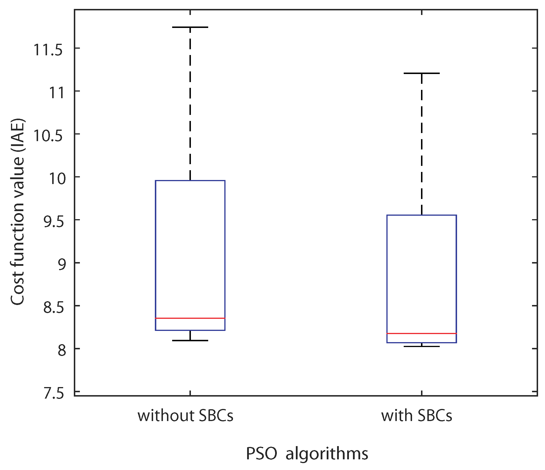
Figure 9 illustrates the box-and-whisker plot of the results of the optimization with and without SBCs for Problem (18). The figure shows that the median line is lower for the PSO algorithm with SBCs than that for the PSO algorithm without SBCs, which indicates that the use of SBCs allows for obtaining better cost function in terms of mean value. Moreover, the box of the algorithm with SBCs is narrower than that the one of the box of the PSO algorithm without SBCs, which means that the algorithm is able to converge to the same region of interesting search space when using SBCs. Both indicators increase the reproductivity of the SBC-based PSO algorithm leading to the optimal solution.
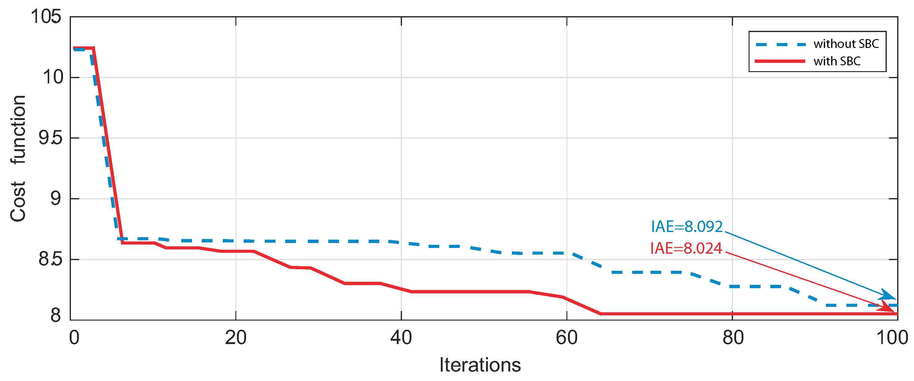
The behavior and performance of the PSO algorithm with and without the SBCs is further observed in the curves of the convergence history shown in Figure 10.
The convergence histories of the best case from optimization trials of Problem (18) using the PSO with and without SBCs show that the PSO algorithm in both cases converges to the same region which proves that it is able to find an interesting search space to explore. In addition, the curves show that with SBCs the algorithm converges to the interesting region in fewer iterations (64 iterations), whereas without SBCs it takes more iterations to reach the interesting region (91 iterations).
From the convergence curves of Figure 10, it is clear that the PSO algorithm manages to converge with fewer iterations to the region of interesting search space when using SBC, which explains the reduced simulation time of Table 2. This is due to the fact that the added symmetry-breaking constraints help narrow the area of search space and eliminates the need to visit symmetric solutions that have already been visited with other sets of variables.

6.2. OWC Performance

For the assessment of the performance of the suggested airflow-control on the OWC system, the optimized PID controller uses the parameters found of the mean case of the PSO optimization results. The evaluation will compare the performance of the uncontrolled OWC, the OWC using a traditionally tuned PID using the well known Ziegler–Nichols method (ZN-PID) and the OWC using the optimized PID using PSO (PSO-PID).
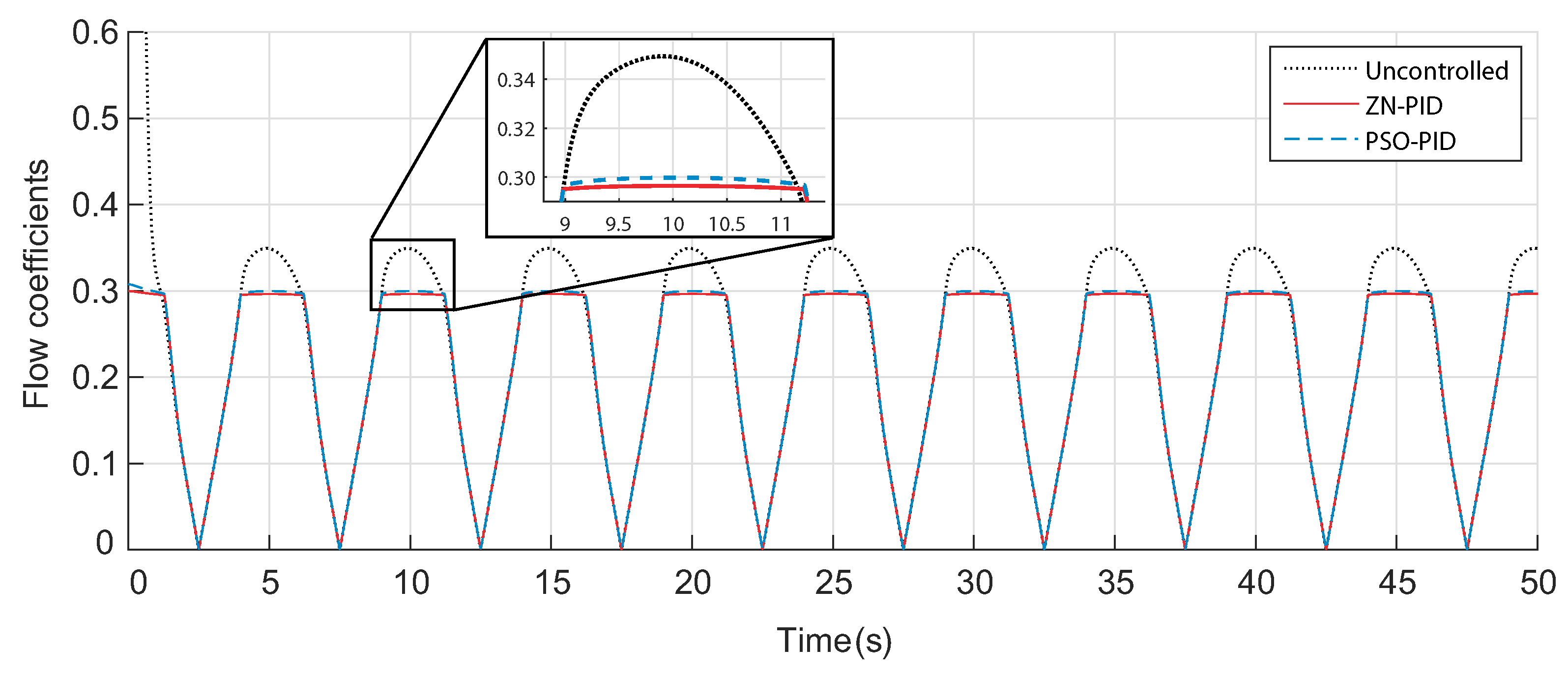
The flow coefficients of the OWC in the uncontrolled case and with the airflow control using the traditionally tuned PID (ZN-PID) and the optimized PID (PSO-PID) are illustrated in Figure 11. The figure shows that in the uncontrolled case the flow coefficient surpasses the threshold value 0.3 which will provoke the stall effect, whereas in both controlled cases the flow coefficients were regulated below 0.3 thanks to both ZN-PID and PSO-PID controllers. However, when zooming to the curves, it is observed that the PSO-PID manages to provide a slightly closer flow coefficient to the threshold value than that of the ZN-PID.
The obtained turbine torques of the PTO are shown in Figure 12. It may be observed that during the uncontrolled case the torque has been affected by the stall effect which reduced it in terms of average value. On the other hand, the airflow control manages to avoid the stall effect and increases the torques in terms of average values.
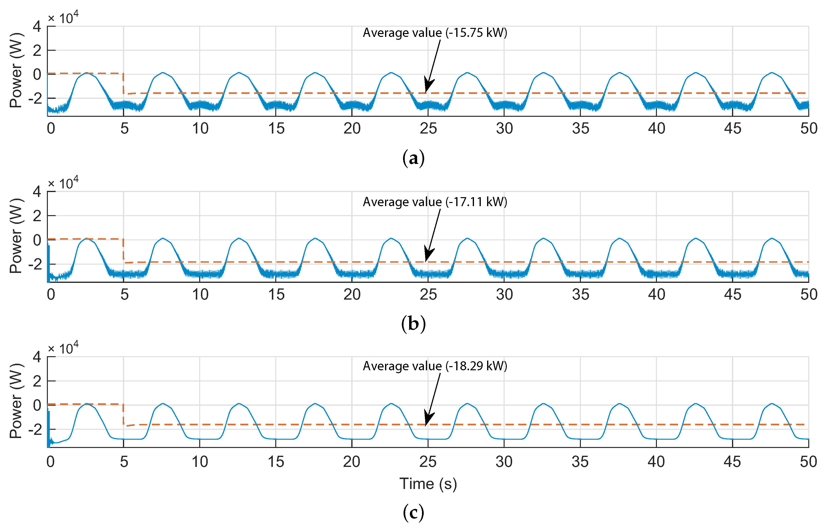
The outputs of the OWC system, which are the generated power, are presented in Figure 13.
As a result from the obtained torques of Figure 12, the generated power in the uncontrolled case is the lowest and the highest power is generated when using the PSO-PID.

7. Conclusions

The paper deals with the stall effect in the OWC system which is known to occur in Wells turbines when a certain airflow speed threshold is exceeded. The research work proposes an airflow control strategy to govern the valve in the air-chamber and avoid the stalling behavior. The PID controller is configured thanks to the Particle Swarm Optimization algorithm.
The PSO algorithm has been simulated to solve the airflow control problem and search for suitable control parameters, but, to further enhance its exploration capabilities, the use of symmetry-breaking constraints was introduced to shrink the search space by eliminating the symmetric solutions. The optimization and computational results indicate amelioration of the PSO performance.
The obtained control parameters from the PSO algorithm were used in the performance evaluation of the suggested airflow control. The operation of the uncontrolled OWC, the OWC using a traditionally tuned PID with the well known Ziegler–Nichols method (ZN-PID), and the OWC using the optimized PID with PSO algorithm (PSO-PID) were compared with the same sea conditions. The results show that the proposed airflow control scheme manages to successfully evade the stall effect in the Wells turbine. Moreover, the airflow control using the PSO-PID demonstrates a superior performance to that of the airflow control using the ZN-PID.

Author Contributions

All authors contributed to the modeling and implementation of the OWC plant. All authors conceived, developed, and implemented the control techniques. All authors analyzed and validated the results. All authors contributed to writing—review and editing the manuscript. All authors have read and agreed to the published version of the manuscript.

Acknowledgments

This work was supported in part by the Basque Government, through project IT1207-19 and by the MCIU/MINECO through RTI2018-094902-B-C21/RTI2018-094902-B-C22 (MCIU/AEI/FEDER, UE).

Conflicts of Interest

The authors declare no conflict of interest.

Nomenclature

The following symbols are used in this manuscript:
λ , A , H Wavelength, amplitude, and height (m)
h , z Sea depth and wave surface elevation (m)
T w , ω Wave period (s) and wave frequency (rad/s)
gAcceleration gravity (m/s 2 )
d P Pressure drop (Pa)
w c , l c Capture chamber inner width and length (m)
V , Q Capture chamber volume (m 3 ) and flow rate (m 3 /s)
ρ , v x Atmospheric density (kg/m 3 ) and airflow speed (m/s)
l , b , D Blade chord length, blade span and turbine diameter (m)
n , p , k , K Blade number, pole number, wave number, and turbine constant
T e , T t Electromagnetic and turbine torques (N·m)
JTurbo-generator inertia (kg·m 2 )
C t , C a , ϕ Torque, power and flow coefficients
R s , R r Stator and rotor resistances ( Ω )
L s , L r Stator and rotor inductances (H)
i s , i r Stator and rotor currents (A)
ψ s , ψ r Stator and rotor flux (Wb)
ω s , ω r Stator and rotor rotational speed (rad/s)
eError between the reference variable and measured variable
uControl signal obtained from the PID controller
K p , K i , K d Proportional, integral, and derivative gains of the PID controller
POptimization problem
x * Optimal solution for the problem
fCost function
φ Penalty function
Λ j Scaling penalty parameter for the jth constraint
n c o n Number of constraints
σ Symmetry permutation
Set of symmetry permutations
x k i , v k i Swarm particles positions and velocities
c 1 , c 2 Cognitive and social scaling factors
wInertia factor
p k i , p k g Best positions formerly found for the ith particle and the entire swarm at the kth iteration

References

  1. Rusu, L.; Onea, F. Assessment of the performances of various wave energy converters along the European continental coasts. Energy 2015, 82, 889–904. [Google Scholar] [CrossRef]
  2. European Parliament. Directive 2009/28/EC of the European Parliament and of the Council of 23 April 2009 on the promotion of the use of energy from renewable sources and amending and subsequently repealing Directives 2001/77/EC and 2003/30/EC. Off. J. Eur. Union 2009, 140, 47. [Google Scholar]
  3. UNFCCC. Adoption of the Paris Agreement FCCC/CP/2015/L. 9/Rev. 1. 1. United Nations Framework Convention on Climate Change. Paris. December 2015. Available online: http://unfccc.int/resource/docs/2015/cop21/eng/l09r01.pdf (accessed on 12 May 2020).
  4. Lavidas, G. Energy and socio-economic benefits from the development of wave energy in Greece. Renew. Energy 2019, 132, 1290–1300. [Google Scholar] [CrossRef]
  5. IRENA. Global Energy Transformation: A Roadmap to 2050, 2019th ed.; International Renewable Energy Agency: Abu Dhabi, UAE, 2019. [Google Scholar]
  6. Lehmann, M.; Karimpour, F.; Goudey, C.A.; Jacobson, P.T.; Alam, M.R. Ocean wave energy in the United States: Current status and future perspectives. Renew. Sustain. Energy Rev. 2017, 74, 1300–1313. [Google Scholar] [CrossRef]
  7. Maria-Arenas, A.; Garrido, A.J.; Rusu, E.; Garrido, I. Control Strategies Applied to Wave Energy Converters: State of the Art. Energies 2019, 12, 3115. [Google Scholar] [CrossRef] [Green Version]
  8. REN21. Renewables 2018 Global Status Report; REN21: Paris, France, 2018. [Google Scholar]
  9. Soukissian, T.H.; Denaxa, D.; Karathanasi, F.; Prospathopoulos, A.; Sarantakos, K.; Iona, A.; Georgantas, K.; Mavrakos, S. Marine Renewable Energy in the Mediterranean Sea: Status and Perspectives. Energies 2017, 10, 1512. [Google Scholar] [CrossRef] [Green Version]
  10. Mustapa, M.A.; Yaakob, O.B.; Ahmed, Y.M.; Rheem, C.K.; Koh, K.K.; Adnan, F.A. Wave energy device and breakwater integration: A review. Renew. Sustain. Energy Rev. 2017, 77, 43–58. [Google Scholar] [CrossRef]
  11. Hayward, J.; Behrens, S.; McGarry, S.; Osman, P. Economic modelling of the potential of wave energy. Renew. Energy 2012, 48, 238–250. [Google Scholar] [CrossRef]
  12. Neary, V.S.; Ahn, S.; Seng, B.E.; Allahdadi, M.N.; Wang, T.; Yang, Z.; He, R. Characterization of Extreme Wave Conditions for Wave Energy Converter Design and Project Risk Assessment. J. Mar. Sci. Eng. 2020, 8, 289. [Google Scholar] [CrossRef] [Green Version]
  13. Konispoliatis, D.N.; Mavrakos, S.A. Wave Power Absorption by Arrays of Wave Energy Converters in Front of a Vertical Breakwater: A Theoretical Study. Energies 2020, 13, 1985. [Google Scholar] [CrossRef] [Green Version]
  14. Aderinto, T.; Li, H. Conceptual Design and Simulation of a Self-Adjustable Heaving Point Absorber Based Wave Energy Converter. Energies 2020, 13, 1997. [Google Scholar] [CrossRef] [Green Version]
  15. Lee, H.H.; Chen, C.-H. Parametric Study for an Oscillating Water Column Wave Energy Conversion System Installed on a Breakwater. Energies 2020, 13, 1926. [Google Scholar] [CrossRef] [Green Version]
  16. Heath, T.V. A review of oscillating water columns. Philos. Trans. R. Soc. A Math. Phys. Eng. Sci. 2012, 370, 235–245. [Google Scholar] [CrossRef] [PubMed] [Green Version]
  17. Raghunathan, S. Performance of the Wells self-rectifying turbine. Aeronaut. J. 1985, 89, 369–379. [Google Scholar]
  18. Raghunathan, S. The Wells air turbine for wave energy conversion. Prog. Aerosp. Sci. 1995, 31, 335–386. [Google Scholar] [CrossRef]
  19. Avery, J. Symmetry-Adapted Basis Sets: Automatic Generation for Problems in Chemistry and Physics; World Scientific: Singapore, 2012. [Google Scholar]
  20. Carter, R.L. Molecular Symmetry and Group Theory; Wiley: New York, NY, USA, 1998; p. 201. [Google Scholar]
  21. Lockwood, E.H.; Macmillan, R.H. Geometric Symmetry; Cambridge University Press Archive: Cambridge, UK, 1978. [Google Scholar]
  22. Kosaka, I.; Swan, C.C. A symmetry reduction method for continuum structural topology optimization. Comput. Struct. 1999, 70, 47–61. [Google Scholar] [CrossRef] [Green Version]
  23. Deü, J.F.; Larbi, W.; Ohayon, R. Piezoelectric structural acoustic problems: Symmetric variational formulations and finite element results. Comput. Methods Appl. Mech. Eng. 2008, 197, 1715–1724. [Google Scholar] [CrossRef]
  24. de León, M.; Cortés, J.; de Diego, D.M.; Martínez, S. General symmetries in optimal control. Rep. Math. Phys. 2004, 53, 55–78. [Google Scholar] [CrossRef]
  25. Kwakernaak, H. Symmetries in control system design. In Trends in Control; Springer: London, UK, 1995; pp. 17–51. [Google Scholar]
  26. Hasan, M.A. On Optimization Problems with Symmetric Constraints. In Proceedings of the 2005 5th International Conference on Information Communications & Signal Processing, Bangkok, Thailand, 6–9 December 2005; pp. 367–371. [Google Scholar]
  27. Walsh, T. Symmetry in constraint optimization. In Proceedings of the Seventh International Workshop on Symmetry in Constraint Satisfaction Problems (SymCon’07) in Conjunction with the International Conference on Principles and Practice of Constraint Programming (CP’2007), Providence, RI, USA, 23–27 September 2007; pp. 1–6. [Google Scholar]
  28. Ji, X.; Ma, F.; Zhang, J. Solving global unconstrained optimization problems by symmetry-breaking. In Proceedings of the 2009 Eighth IEEE/ACIS International Conference on Computer and Information Science, Shanghai, China, 1–3 June 2009; pp. 107–111. [Google Scholar]
  29. Puget, J.F. On the satisfiability of symmetrical constrained satisfaction problems. In Proceedings of the 7th International Symposium on Methodologies for Intelligent Systems (ISMIS’93), Trondheim, Norway, 15–18 June 1993; pp. 350–361. [Google Scholar]
  30. Crawford, J.; Ginsberg, M.; Luks, E.; Roy, A. Symmetry-breaking predicates for search problems. In Principles of Knowledge Representation and Reasoning: Proceedings of the Fifth International Conference (KR’96); Morgan Kaufmann Publishers: San Francisco, CA, USA, 1996; pp. 148–159. [Google Scholar]
  31. Puget, J.F. An efficient way of breaking value symmetries. In Proceedings of the Twenty-First National Conference on Artificial Intelligence (AAAI-06), Boston, MA, USA, 16–20 July 2006; pp. 117–122. [Google Scholar]
  32. Gent, I.P.; Smith, B.M. Symmetry breaking in constraint programming. In Proceedings of ECAI-2000; IOS Press: Amsterdam, The Netherlands, 2000; pp. 599–603. [Google Scholar]
  33. Fahle, T.; Schamberger, S.; Sellmann, M. Symmetry breaking. In Proceedings of the 7th International Conference on Principles and Practice of Constraint Programming (CP2001), Paphos, Cyprus, 26 November–1 December 2001; Springer: Berlin, Germany, 2001; pp. 93–107. [Google Scholar]
  34. Roney-Dougal, C.M.; Gent, I.P.; Kelsey, T.; Linton, S. Tractable symmetry breaking using restricted search trees. In Proceedings of the 16th European Conference on Artificial Intelligence (ECAI 2004), Valencia, Spain, 22–27 August 2004; pp. 211–215. [Google Scholar]
  35. Legowski, A.; Niezabitowski, M. Robot path control based on PSO with fractional-order velocity. In Proceedings of the International Conference on Robotics and Automation Engineering (ICRAE), Jeju Island, Korea, 27–29 August 2016; pp. 21–25. [Google Scholar]
  36. M’zoughi, F.; Bouallègue, S.; Garrido, A.J.; Garrido, I.; Ayadi, M. Water Cycle Algorithm-based Airflow Control for an Oscillating Water Column-based Wave Generation Power Plant. Proc. Inst. Mech. Eng. Part I J. Syst. Control Eng. 2020, 234, 118–133. [Google Scholar]
  37. M’zoughi, F.; Bouallègue, S.; Ayadi, M.; Garrido, A.J.; Garrido, I. Harmony Search Algorithm-based Airflow Control of an Oscillating Water Column-based Wave Generation Power Plants. In Proceedings of the 2018 International Conference on Advanced Systems and Electric Technologies (IC_ASET), Hammamet, Tunisia, 22–25 March 2018; pp. 249–254. [Google Scholar]
  38. M’zoughi, F.; Bouallègue, S.; Garrido, A.J.; Garrido, I.; Ayadi, M. Stalling-free Control Strategies for Oscillating-Water-Column-based Wave Power Generation Plants. IEEE Trans. Energy Convers. 2018, 33, 209–222. [Google Scholar] [CrossRef]
  39. M’zoughi, F.; Garrido, I.; Bouallègue, S.; Ayadi, M.; Garrido, A.J. Intelligent Airflow Controls for a Stalling-Free Operation of an Oscillating Water Column-Based Wave Power Generation Plant. Electronics 2019, 8, 70. [Google Scholar] [CrossRef] [Green Version]
  40. Eberhart, R.C.; Kennedy, J. A new optimizer using particle swarm theory. In Proceedings of the 6th International Symposium on Micro Machine and Human Science MHS’95, Nagoya, Japan, 4–6 October 1995; pp. 39–43. [Google Scholar]
  41. Clerc, M.; Kennedy, J. The Particle Swarm-Explosion, Stability, and Convergence in a Multidimensional Complex Space. IEEE Trans. Evolut. Comput. 2002, 6, 58–73. [Google Scholar] [CrossRef] [Green Version]
  42. AlRashidi, M.R.; El-Hawary, M.E. A survey of particle swarm optimization applications in electric power systems. IEEE Trans. Evol. Comput. 2008, 13, 913–918. [Google Scholar] [CrossRef]
  43. Robinson, J.; Rahmat-Samii, Y. Particle swarm optimization in electromagnetics. IEEE Trans. Antennas Propag. 2004, 52, 397–407. [Google Scholar] [CrossRef]
  44. Pandey, S.; Wu, L.; Guru, S.M.; Buyya, R. A particle swarm optimization-based heuristic for scheduling workflow applications in cloud computing environments. In Proceedings of the 2010 24th IEEE International Conference on Advanced Information Networking and Applications, Perth, Australia, 20–23 April 2010; pp. 400–407. [Google Scholar]
  45. M’zoughi, F.; Garrido, I.; Garrido, A.J.; De La Sen, M. ANN-Based Airflow Control for an Oscillating Water Column Using Surface Elevation Measurements. Sensors 2020, 20, 1352. [Google Scholar] [CrossRef] [Green Version]
  46. Sobey, R.; Goodwin, P.; Thieke, R.; Westberg, R.J., Jr. Application of Stokes, Cnoidal, and Fourier wave theories. Waterw. Port Coast. Ocean Eng. 1987, 113, 565–587. [Google Scholar] [CrossRef]
  47. Le Roux, J.P. An extension of the Airy theory for linear waves into shallow water. Coast. Eng. 2008, 55, 295–301. [Google Scholar] [CrossRef]
  48. Garrido, A.J.; Otaola, E.; Garrido, I.; Lekube, J.; Maseda, F.J.; Liria, P.; Mader, J. Mathematical Modeling of Oscillating Water Columns Wave-Structure Interaction in Ocean Energy Plants. Math. Probl. Eng. 2015, 2015, 727982. [Google Scholar] [CrossRef] [Green Version]
  49. Sarmento, A.J.N.A.; de O. Falcão, A.F. Wave generation by an oscillating surface-pressure and its application in wave-energy extraction. J. Fluid Mech. 1985, 150, 467–485. [Google Scholar] [CrossRef]
  50. Falcão, A.F.O.; Rodrigues, R.J.A. Stochastic modelling of OWC wave power plant performance. Appl. Ocean Res. 2002, 24, 59–71. [Google Scholar] [CrossRef]
  51. Falcão, A.F.O.; Gato, L.M.C. Air Turbines. In Comprehensive Renewable Energy; Sayigh, A., Ed.; Elsevier: Oxford, UK, 2012; Volume 8, pp. 111–149. [Google Scholar] [CrossRef]
  52. López, I.; Andreu, J.; Ceballos, S.; de Alegría, I.M.; Kortabarria, I. Review of wave energy technologies and the necessary power-equipment. Renew. Sustain. Energy Rev. 2013, 27, 413–434. [Google Scholar] [CrossRef]
  53. Setoguchi, T.; Takao, M. Current status of self rectifying air turbines for wave energy conversion. Energy Convers. Manag. 2006, 47, 2382–2396. [Google Scholar] [CrossRef]
  54. O’Sullivan, D.L.; Lewis, A. Generator selection and comparative performance in offshore oscillating water column. IEEE Trans. Energy Convers. 2011, 26, 603–614. [Google Scholar] [CrossRef]
  55. Alberdi, M.; Amundarain, M.; Garrido, A.J.; Garrido, I.; Casquero, O.; De la Sen, M. Complementary control of oscillating water column-based wave energy conversion plants to improve the instantaneous power output. IEEE Trans. Energy Convers. 2011, 26, 1021–1032. [Google Scholar] [CrossRef]
  56. Muller, S.; Diecke, M.; De Donker, R.W. Doubly fed induction generator systems for wind turbines. IEEE Ind. Appl. Mag.. 2002, 26–33. [Google Scholar] [CrossRef]
  57. Ledesma, P.; Usaola, J. Doubly fed induction generator model for transient stability analysis. IEEE Trans. Energy Convers. 2005, 20, 388–397. [Google Scholar] [CrossRef]
  58. Lima, R.M.; Novais, A.Q. Symmetry breaking in MILP formulations for unit commitment problems. Comput. Chem. Eng. 2016, 85, 162–176. [Google Scholar] [CrossRef] [Green Version]
  59. Law, Y.C.; Lee, J.H.M. Symmetry breaking constraints for value symmetries in constraint satisfaction. Constraints 2006, 11, 221–267. [Google Scholar] [CrossRef]
  60. Walsh, T. General symmetry breaking constraints. In Proceedings of the International Conference on Principles and Practice of Constraint Programming, Nantes, France, 25–29 September 2006; pp. 650–664. [Google Scholar]
  61. Eberhart, R.C.; Shi, Y. Particle Swarm Optimization: Developments, Applications and Resources. In Proceedings of the IEEE Congress on Evolutionary Computation, Seoul, Korea, 27–30 May 2001; pp. 81–86. [Google Scholar]
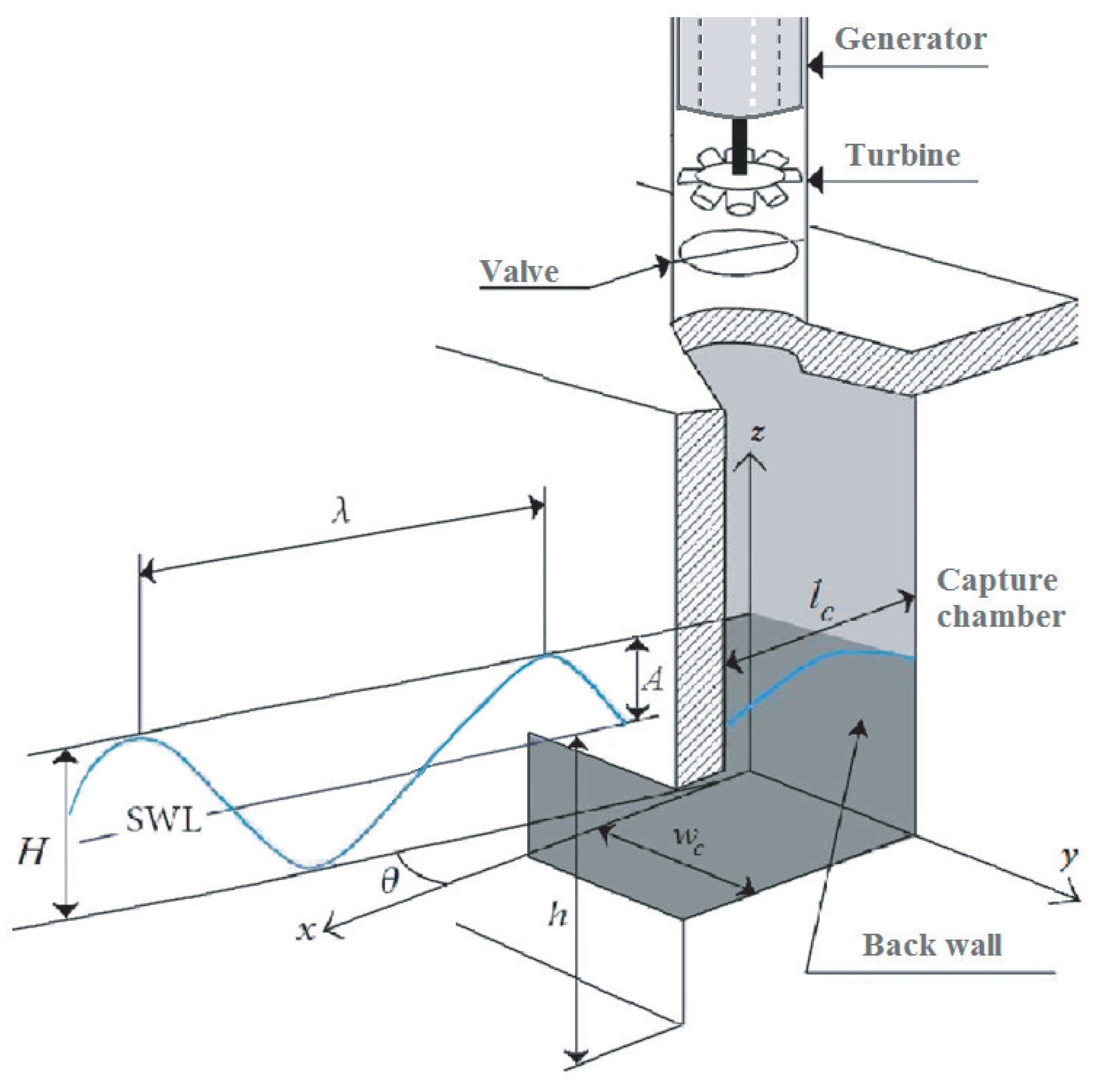
Figure 1. Sketch of a Oscillating Water Column system and the sea wave [45].
Symmetry 12 00895 g001
Figure 2. Wells turbine and the DFIG-based OWC system [45].
Symmetry 12 00895 g002
Figure 3. Wells turbine’s characteristic curves. (a) power coefficient against flow coefficient; (b) torque coefficient against flow.
Symmetry 12 00895 g003
Figure 4. Airflow velocity evolution with different wave amplitudes and periods [45].
Symmetry 12 00895 g004
Figure 5. Flow coefficient during two different wave conditions [45].
Symmetry 12 00895 g005
Figure 6. Turbine torques during two different wave conditions [45].
Symmetry 12 00895 g006
Figure 7. Airflow control scheme strategy for OWC plant equipped with Wells turbine [39].
Symmetry 12 00895 g007
Figure 8. PSO-based airflow control scheme for the Wells turbine-based OWC plant.
Symmetry 12 00895 g008
Figure 9. Box-and-whisker plot of the optimization results with and without SBCs for Problem (18).
Symmetry 12 00895 g009
Figure 10. Convergence histories of the PSO algorithm with and without SBCs for Problem (18).
Symmetry 12 00895 g010
Figure 11. Flow coefficients of the OWC in uncontrolled and controlled cases.
Symmetry 12 00895 g011
Figure 12. Turbine torque of the OWC. (a) in the uncontrolled case; (b) with ZN-PID, (c) with PSO-PID.
Symmetry 12 00895 g012
Figure 13. Generated power of the OWC. (a) in the uncontrolled case; (b) with ZN-PID; (c) with PSO-PID.
Symmetry 12 00895 g013
Table 1. Oscillating Water Column’s parameters from the NEREIDA wave power plant.
Capture ChamberWells TurbineDFIG Generator
w c = 4.5 mn = 5 R s = 0.5968 Ω P r a t e d = 18.45 kW
l c = 4.3 mb = 0.21 m R r = 0.6258 Ω V s r a t e d = 400 V
ρ a =1.19 kg/m 3 l = 0.165 m L s s = 0.0003495 H f r a t e d = 50 Hz
ρ w = 1029 kg/m 3 r = 0.375 m L r r = 0.324 H p = 2
a = 0.4417 m 2 L m = 0.324 H
Table 2. Computational and Optimization Results from 20 Trials of Problem (18).
SBCCost FunctionCPU Time (s)
WorstMeanBestS.D.WorstMeanBest
without11.74338.35768.09271.6928709167456492
with11.20618.33248.02431.4491587656045328