1. Introduction
The racing car life cycle is very short, and designers are always under pressure because of expenses, design innovations, material requirements, and precise manufacturing. The design of the upright is limited by the number of predefined physical vehicle body parameters, dynamic and kinematic requirements, and last but not least by the wheel suspension geometry [
1].
To successfully cope with a task such as the topology optimization of an upright, knowledge on the design of accurate machine components is necessary. In addition, both theoretical and practical knowledge of additive manufacturing is also necessary. The upright is one of the main components of the formula suspension system, and due to the fact that this is a component that has a major impact on the unsprung weight, which directly affects the driving properties, it is very desirable that its weight be as low as possible [
2].
However, the reduction in the weight of the upright could not be, in this case, the only goal, because it is also necessary to maintain sufficient stiffness; therefore, a compromise has to be found between weight, strength, and stiffness [
3,
4,
5].
Since the topology optimization means a change in shape while maintaining some of its properties, the goal is the effective use of the build material for the manufacturing of the upright. Due to the fact that the resulting optimized design of the component is often very difficult to manufacture by conventional production methods, it provides a natural connection with the modern methods of additive manufacturing, which are suitable for the production of dimensionally complex parts [
6].
Since the 1970s, many optimization methods have been developed during intensive research on topological optimization. Most remained only on the theoretical level due to lack of computational power. Two main methods, each representing a different approach to the solution, have been put to practical use in the solution of material distribution [
7,
8,
9].
2. Materials and Methods
2.1. Basic Requirements for an Upright Design
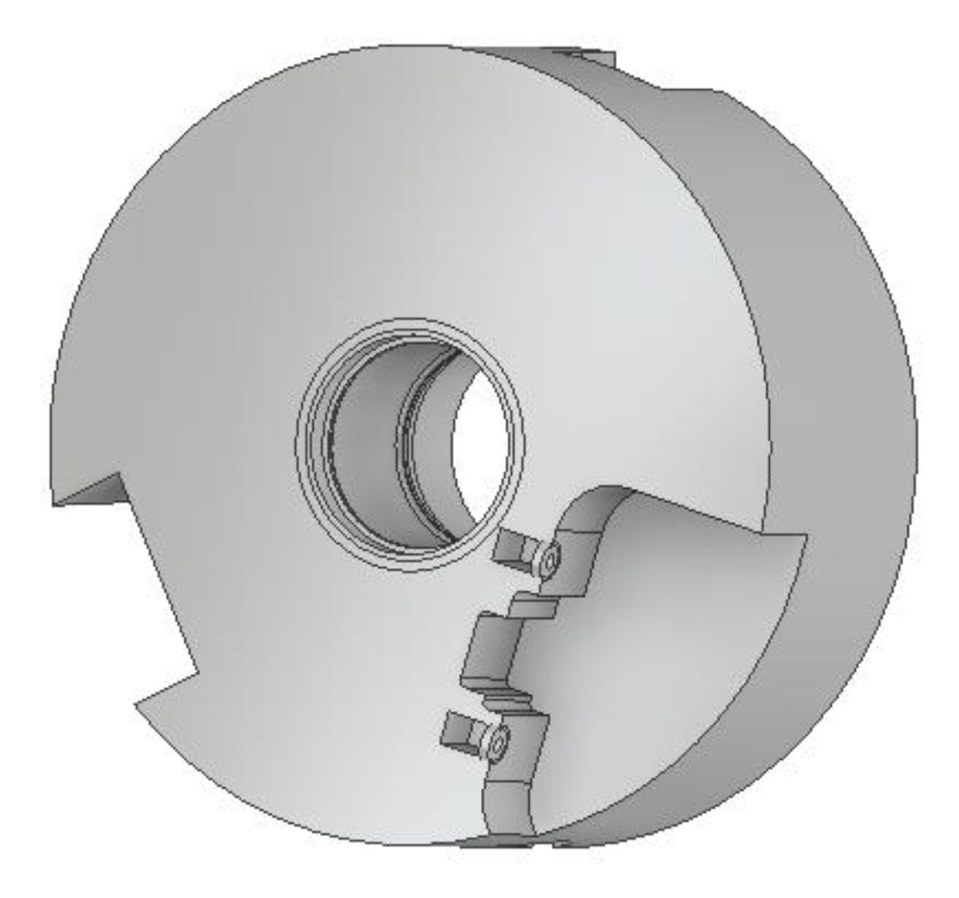
The upright transfers braking, driving, and steering forces and moments from the road and wheel to the suspension and vice versa. The upright is mounted in two bearings, which have to be able to absorb radial and axial forces. The driving shaft of the driving axle is mounted on the side of the upright with respect to the homokinetic joints for torque transmission.
Bearings in the chassis can be single row or double row, mostly with angular contact to provide axial force transmission. A brake drum or a brake disk is attached to the upright. A rim is mounted on a hub by screws or nuts and secured with one central nut.
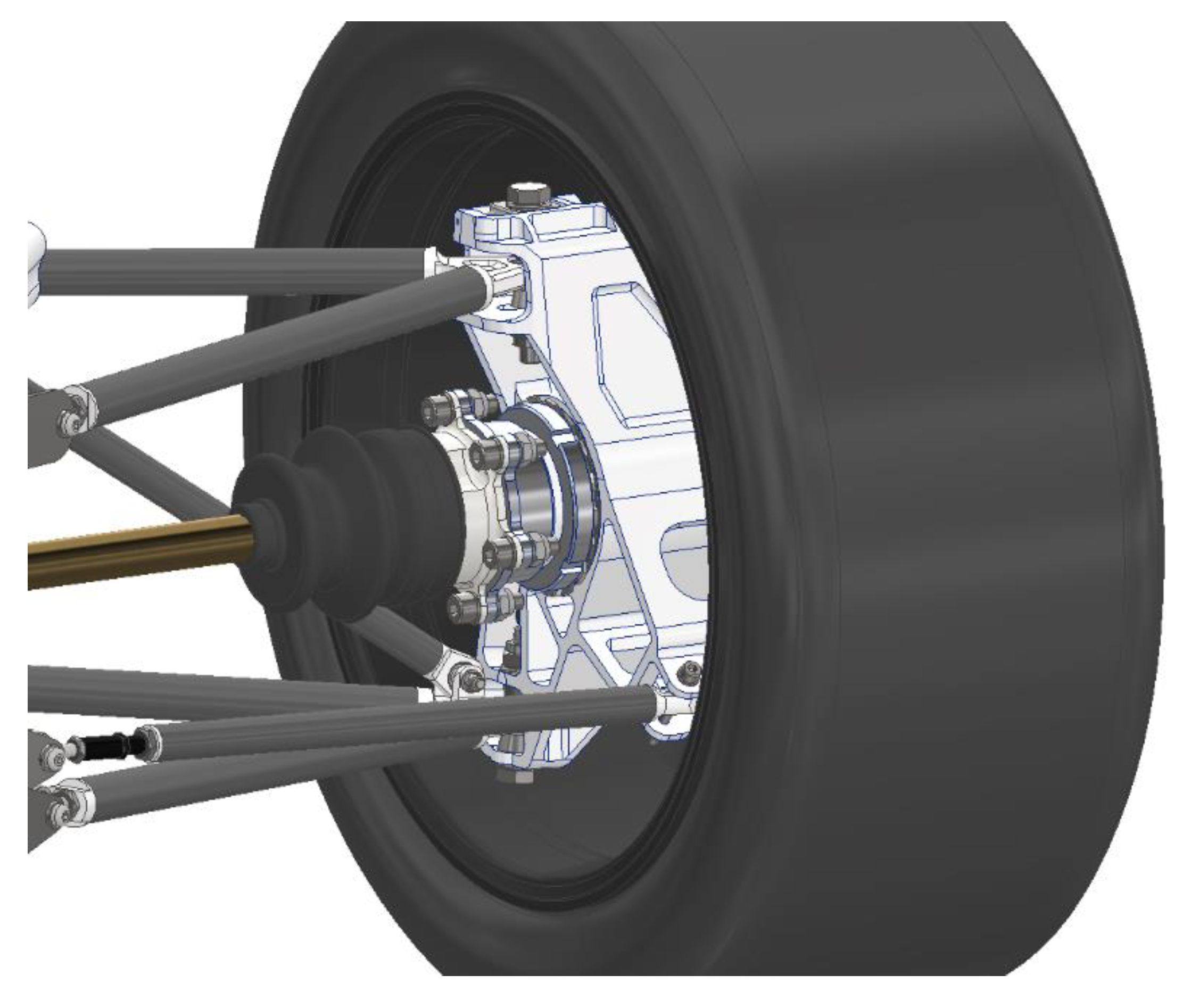
A racing car’s upright has different design options which correspond to the vehicle’s suspension configuration. For production cars, the uprights are produced by the casting of gray cast iron or steel. For the racing cars, weight is the key parameter. Due to this reason, the uprights are made of expensive materials using advanced manufacturing methods. The upright structure is mostly affected by the type of suspension and production technology used. The whole assembly of the rear hub with the upright and wheel is shown in
Figure 1. The basic requirements for racing car upright should be:
Minimal weight,
Maximal stiffness,
Sufficient strength.
2.2. Topology Optimization and Additive Manufacturing
Three-dimensional printing based on selective laser melting (SLM) is also known as powder bed fusion technology that utilizes atomized metal powder, which is applied layer by layer on the build platform and then sintered into the desired shape by a laser beam.
This method is capable of complex shapes which are practically unattainable by conventional manufacturing technologies. Another issue which could arise is manufacturing cost. For conventional manufacturing, it is generally known that the more complex the shape, the more expensive the manufacturing. The issue can be addressed via additive manufacturing because of its nature, which allows the production of complex shapes much more easily than with conventional manufacturing technologies like machining. The main limitation for SLM is the manufacturing of unsupported overhangs under critical angles (typically less than 45°). For the successful manufacturing of the part and the effective usage of the selective laser melting system, two key parameters must be held. The first parameter is the positioning of the printed part on the building platform in order to obtain a position with a minimal volume of supports. The relationship between the complexity of shape and production costs does not apply fully to parts produced on a selective laser melting system. In some cases it can be even opposite, because the more complex shape is more self-supporting than the simple shape and, as a result, fewer supports for overhangs are generated.
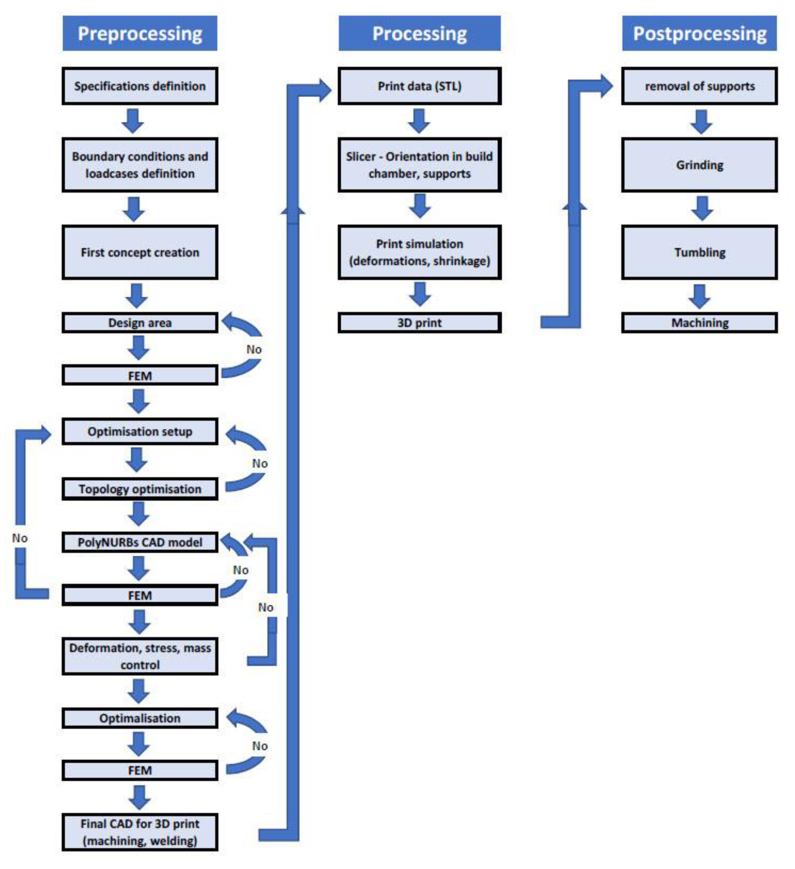
Figure 2 shows the whole process of topology optimization [
10,
11,
12].
2.3. Principle of Topology Optimization
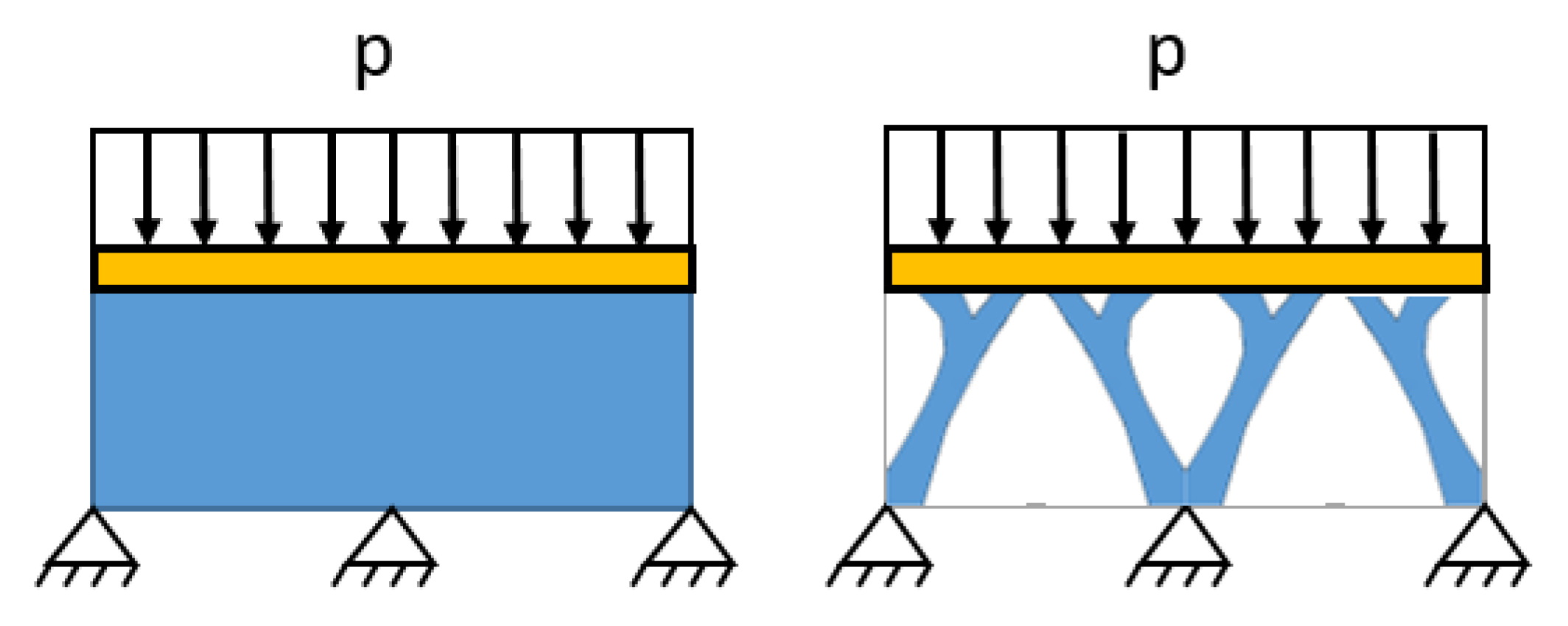
The principle of topology optimization can be explained by way of the example in
Figure 3, where we want to determine the volume of supportive structure needed to support a homogeneously distributed load on the surface. As
Figure 3 shows, in its lower part there are three fixed supports [
13,
14].
By topology optimization, we make a model of this structure as surface loaded by a homogeneously distributed load on it. Three fixed supports, one at each side and in the middle of the beam, are used. The outcome corresponds to the desired design, with a minimal volume of used material. The generated shape transfers the pressure load onto fixed supports. The model needs to be smoothed in order to obtain a continual surface mesh for the best manufacturability and end usability in a real-world scenario [
15,
16,
17].
2.4. Definition of Conception
The simulation of topology optimization is preceded by defining the design space, material, loads, supports, and non-design spaces. The forces on the uprights were calculated in the MSC Adams (MSC Software, Newport Beach, CA, USA) software when designing the suspension [
18]. Another important factor is the choice of material, which must be 3D printable and have the appropriate qualities required by the design of the upright. The dimensions of the rear upright are determined by the position of the attachment points of the suspension, the rear hub, and the brake caliper. There is a symmetry between the right and left upright, and thus the opposite upright can only be mirrored.
The goal of topological optimization was set to reduce the weight of the upright by 30–40% of the total weight of the milled upright from last season and to maintain a sufficient stiffness. The milled upright weighed 1175 g, and thus a topologically optimized upright should reach a weight of around 750 g.
2.5. Materials
Firstly, a table of all the available metal printable materials was determined (see
Table 1) and assigned the prices of the additive manufacturing powders and the most important mechanical parameters that affect the weight, deformation, and yield strength of the part.
AlSi10Mg, Ti6Al4V ELI, and Maraging steel M300 were considered for our topologically optimized upright as materials. Ti6Al4V ELI features very high-quality properties for printing racing parts. It has a large yield strength, sufficient modulus of elasticity, and medium density. The big disadvantage of titanium alloys is the price of their powder, which is around 2900 € for 10 Kg of powder. Maraging steel excels with its large yield strength and high modulus of elasticity. The disadvantage of Maraging steel is its density, which exceeds 8 g/cm
3, and thus the walls would have to be very thin to achieve our goal of reducing the weight of the upright by 30–40%. AlSi10Mg aluminum alloy is characterized by its low density, low yield strength, and low modulus of elasticity. The walls of AlSi10Mg must be large enough for the upright to be stiff, which the density of the AlSi10Mg allows. Aluminum alloy was also used for uprights produced by conventional methods of previous seasons of our formula student team; therefore, we have experience with this material. Another advantage of AlSi10 is its low cost of powder. Comparing these three materials, AlSi10Mg was selected as the material for the topologically optimized upright [
13,
21].
The disadvantage of AlSi10Mg is its low yield strength of 200 MPa compared to today’s high-strength aluminum alloys, which reach yield strength of up to 400 MPa. High-strength aluminum alloys are not used for 3D printing due to their susceptibility to embrittlement. The AlSi10Mg is characterized by a high thermal conductivity, high corrosion resistance, and decent response to post process finishing. The material properties of AlSi10Mg are shown in
Table 2.
2.6. Creation of Design Space
In order to start the simulation, it is necessary to define the design space which gives information on the software and which areas can be optimized. It is good to have a design space as big as possible. At the same time, the design space should be simple in shape because of the time reduction in the calculation. It is very important to check the design space in whole assembly for possible collisions.
At the beginning, a cylinder with the same diameter as the wheel rim was created. Secondly, the volumes for components such the brake caliper and suspension arms were removed. As the process progressed, we achieved the shape of the design space, as shown
Figure 4 and
Figure 5.
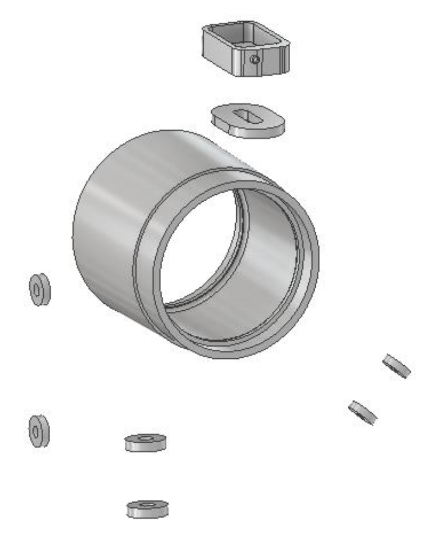
2.7. Set a Non-Design Parts
Non-design space includes parts that must be preserved untouched by the optimizing algorithm. Non-design space is represented by mounting places for the bearings, brake discs, suspension arms, and tie rod. Although parts of the non-design space cannot be altered by topology optimization, they can be optimized by removing unnecessary material. The inner ring was optimized from 0.4 kg to 0.25 kg. In addition, it was necessary to create components for fixing the brake caliper. The brake caliper is attached to the upright by two screws. In the place of attachment, rings were formed, which were dimensioned according to the diameter of the screw washer. The fit of the upper arm must stay movable for setting the wheel camber. Components for fixing the lower arm and push rod were created in the same way as for the brake caliper. The whole non-design space is shown in
Figure 6.
2.8. Set of the Loads and Supports
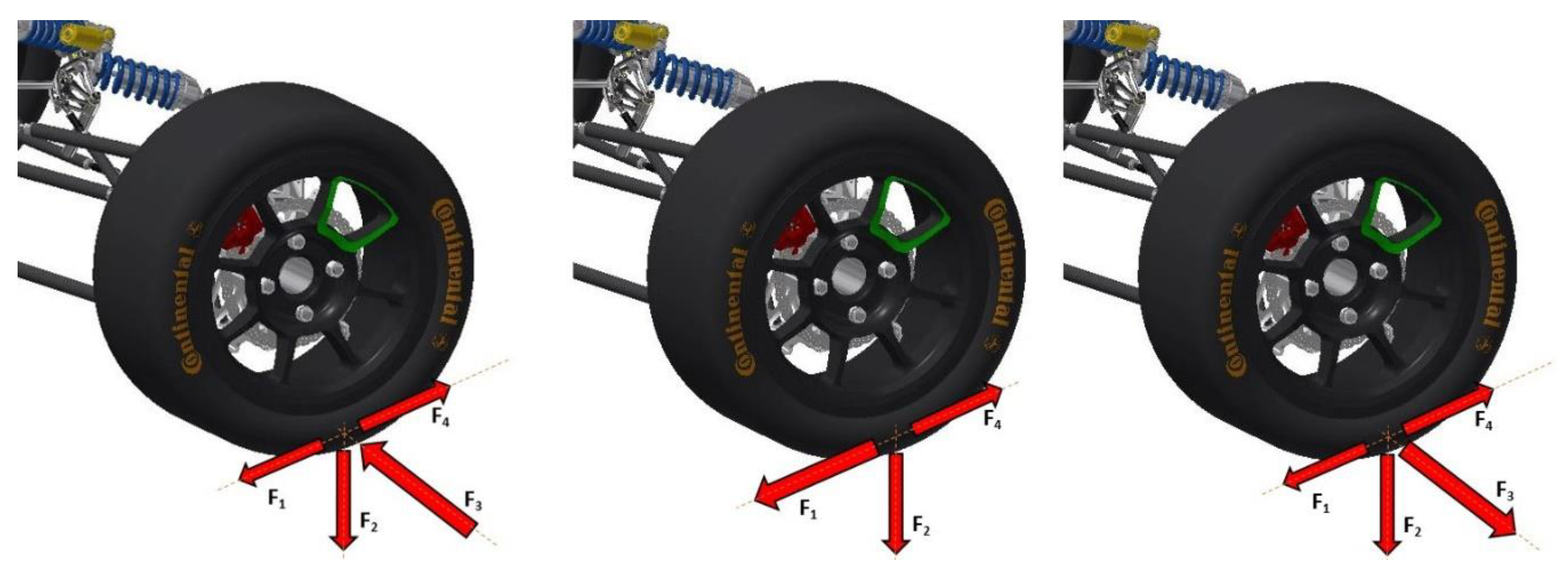
From the dimensions of the vehicle and its estimated weight, forces acting on a wheel at the point of contact of the tire with the road are determined (see
Figure 7). These are further used as an input to the multi-body simulation in Adams software. Here, the forces are converted into reaction forces acting at the points where the rod is attached to the vehicle. F
1 = braking force, F
2 = gravitational force, F
3 = lateral force, F
4 = reaction force from torque.
The three load cases were set–acceleration, braking, and cornering. Each of these load cases are characterized by the biggest reaction force. The load cases are set for a camber of 1.2 degrees and when the suspension is compressed by 25 mm. The cornering is defined as a maximum lateral force that a tire can transform before a skid occurs.
During hard braking, the greatest braking force that is generated from the brake caliper is transmitted to the brake caliper mounting bracket of the upright. The most burdensome state is cornering with a camber of 1.2 degrees and with braking where the acting forces to the lower arm (3500 N), upper arm (2000 N), steering rod (1220 N), push rod (3300 N), and braking moment from the braking caliper (146 Nm).
The upright is mounted in two ball bearings which transmit forces from the tires to upright. The forces are further transmitted from the upright to the suspension. The fixed supports were placed into main inner ring, wherein the ball bearing was mounted. The supports fix the upright against displacement both in the radial direction and in the axial direction.
2.9. Topology Optimization
Evolutionary Structural Optimization (ESO) is the name of a method whose principle is to calculate the required criterion (reduced stress, deformation) in each solution iteration. Based on the result, the elements with the smallest value are removed from the area under consideration. This method is random, which means that it searches for an “optimal” solution in a set of large numbers of generated solutions. However, at least the local optimum is not guaranteed. Theoretical principles more deeply are discussed in [
22,
23,
24,
25] together with examples of practical usage.
Solid Isotropic Microstructure with Penalization (SIMP) is a gradient numerical method [
26] which calculates the distribution of the variable in the specified area. The individual elements are assigned a value from the interval 0–1, which determines the proportion of, for example, the density or thickness of the material at a given location. From a practical point of view, it is necessary to divide the area only into elements with a value of exactly 1 or 0. This is done by so-called penalization methods, which deal with the values within the interval.
The topological calculation itself was performed using the SolidThinking Inspire (Altair, Troy, MI, USA) software [
27]. The software uses the OptiStruct solver core for optimization. OptiStruct uses the SIMP method to solve topological optimization tasks [
28].
Once the material, forces, design space, non-design space, and supports are defined, the simulation is ready to start. The goal of optimization was to minimize the weight by 30–40% of the milled upright while maintaining the stiffness; therefore, it was decided to reduce the mass to 5% of the total design space volume and set the objective of the analyses to maximize the stiffness. The minimal thickness of the optimized part was defined as 5 mm. The smaller the optimized part thickness, the longer the simulation takes [
29,
30]. The summary of the analysis setting is shown in
Table 3.
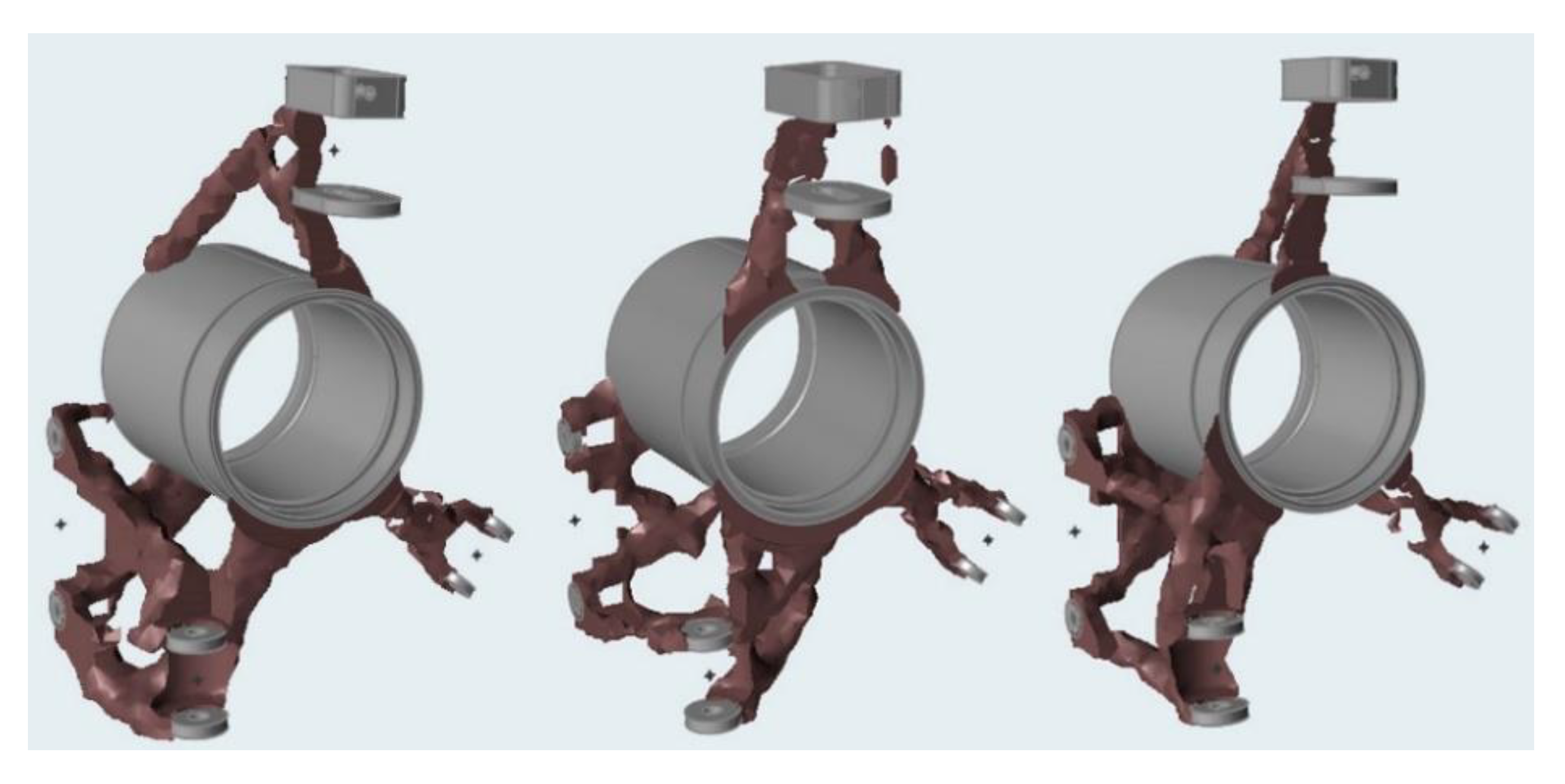
Three output results from each load case was obtained (as shown
Figure 8). For the final solution, a combination of these three outputs was used.
2.10. Creation of a 3D Model
There are two options on how to create a model with data from the simulation.
The first option uses modelling surfaces using the function polyNURBS and then subsequently imports the model into any of the CAD programs for editing the other parameters.
The other way is to edit the polygonal data in software that allows you to work with them.
We decided to use the software SolidThinking Inpsire and subsequent modifications in Autodesk Inventor (Autodesk, San Rafael, CA, USA) [
31]. The modelling was based on three results (
Figure 9) of the topologically optimized simulation. We tried to form the surfaces into beam shapes in order to increase the strength and stiffness of the upright. The final model (
Figure 9) was created after the third iteration.
2.11. Finite Element Assessment of the Upright
Topology optimization is an iterative process; once the first model of the upright is finished, it is followed by a finite element method (FEM) analysis. The FEM analysis must verify each load case. This analysis shows places within a model which can withstand load and places which should be reinforced. In places with a larger factor of safety, material should be removed and added to the highly stressed places. This process is repeated until the model reaches a 30–40% weight of the milled upright and can withstand the calculated load. The weight rise or reduction should be one of the assessed quantities.
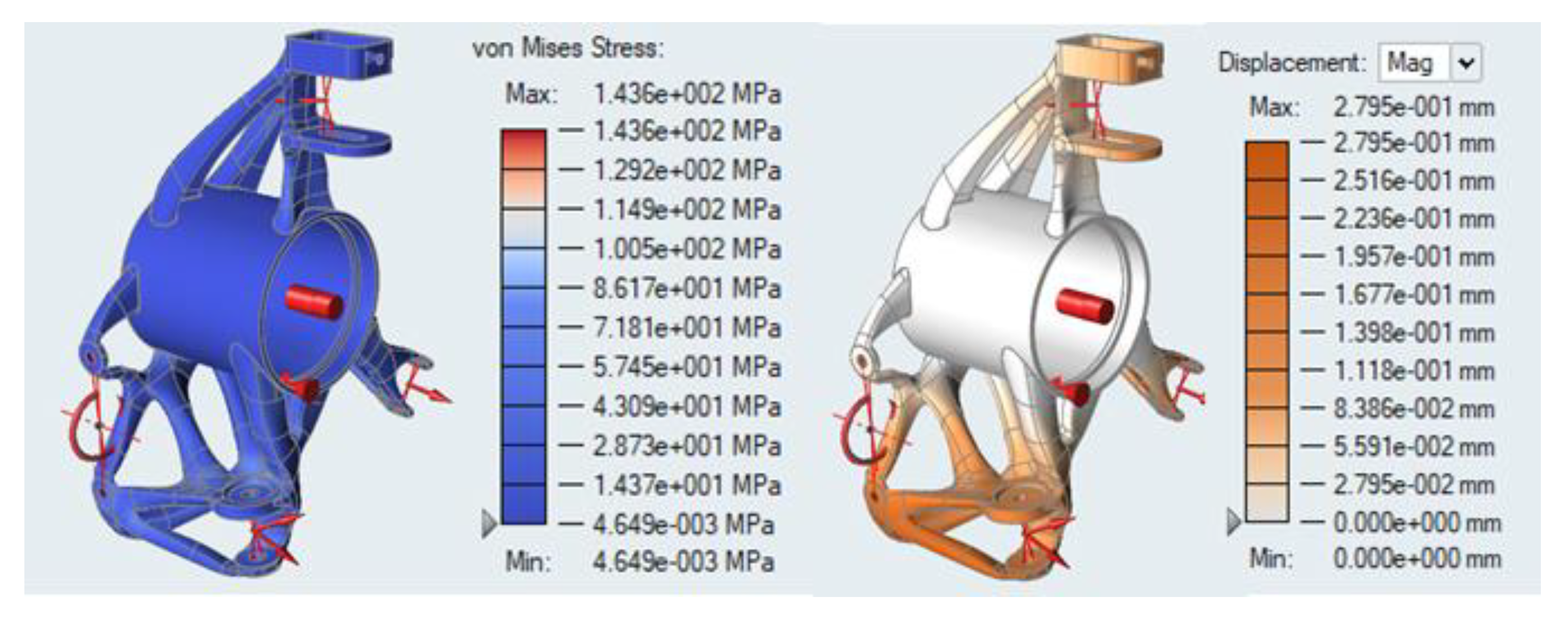
The first was material, forces, and supports set up, then the element size was determined to 1 mm. Our final upright was three times modified until the results were satisfactory. The maximal stress was 143 MPa in the peak of the seating of the lower arm, what is less than the yield strength of the aluminum alloy used. The maximum deformation of the upright when cornering is 0.28 mm, as shown in
Figure 10.
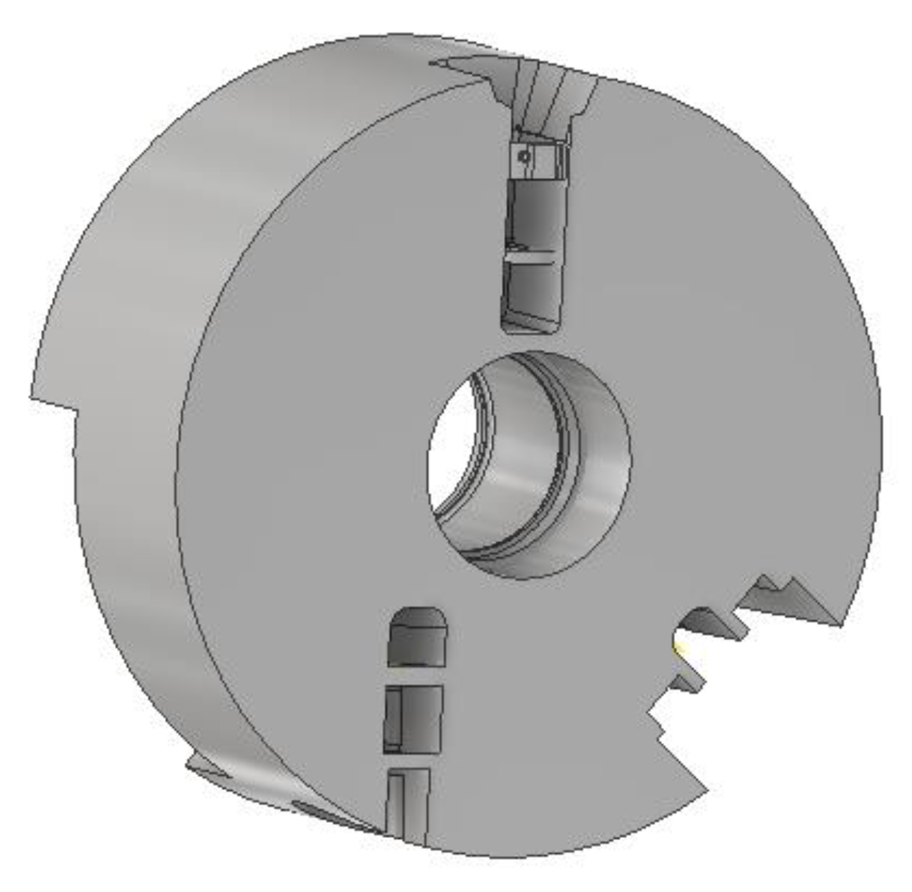
2.12. Machining Allowances
Machining allowances have been added to the places to be machined. Holes that must be within tolerances have been blinded and will be drilled after printing. The material from the other holes has been removed by 0.2 mm in diameter because of SLM inaccuracies. Grooves were solved as holes, and the material in the diameter was removed. The main machining allowances are placed where the upright rests on the bearings. There, we put a 1 mm allowance to each side, which means 2 mm added in diameter. These surfaces will be machined after printing [
32].
2.13. Printing Process Preparation
Once the final model of the upright was finished, preparing to manufacture it began. The 3D model of the upright was put into the software Materialise Magics (Materialise NV, Leuven, Belgium) [
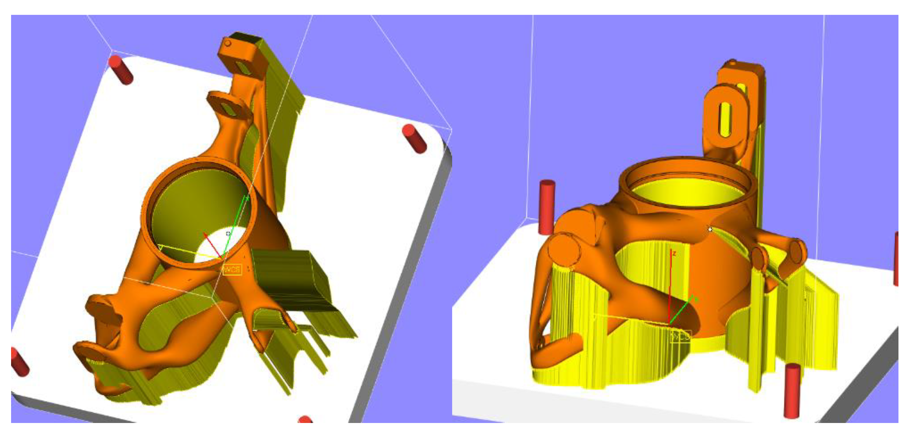
33]. It is a specialized data preparation program for additive production, particularly in creating the position and supports of the printed part. The upright has been put on a platform for manufacturing. First, a position for the upright on the platform was created. The position should be determined so that a large volume of material does not appear in one layer during construction, nor should it be parallel or perpendicular to the cutting edge of the recoater. The software Magics automatically generates supports and positions that cannot take place without modification, therefore we modified supports to the state that does not intersect the model. It is also important to consider the heat dissipation from places with a large volume of material.
Figure 11 shows a view of the upright in the Materialize Magics software.
2.14. Manufacturing
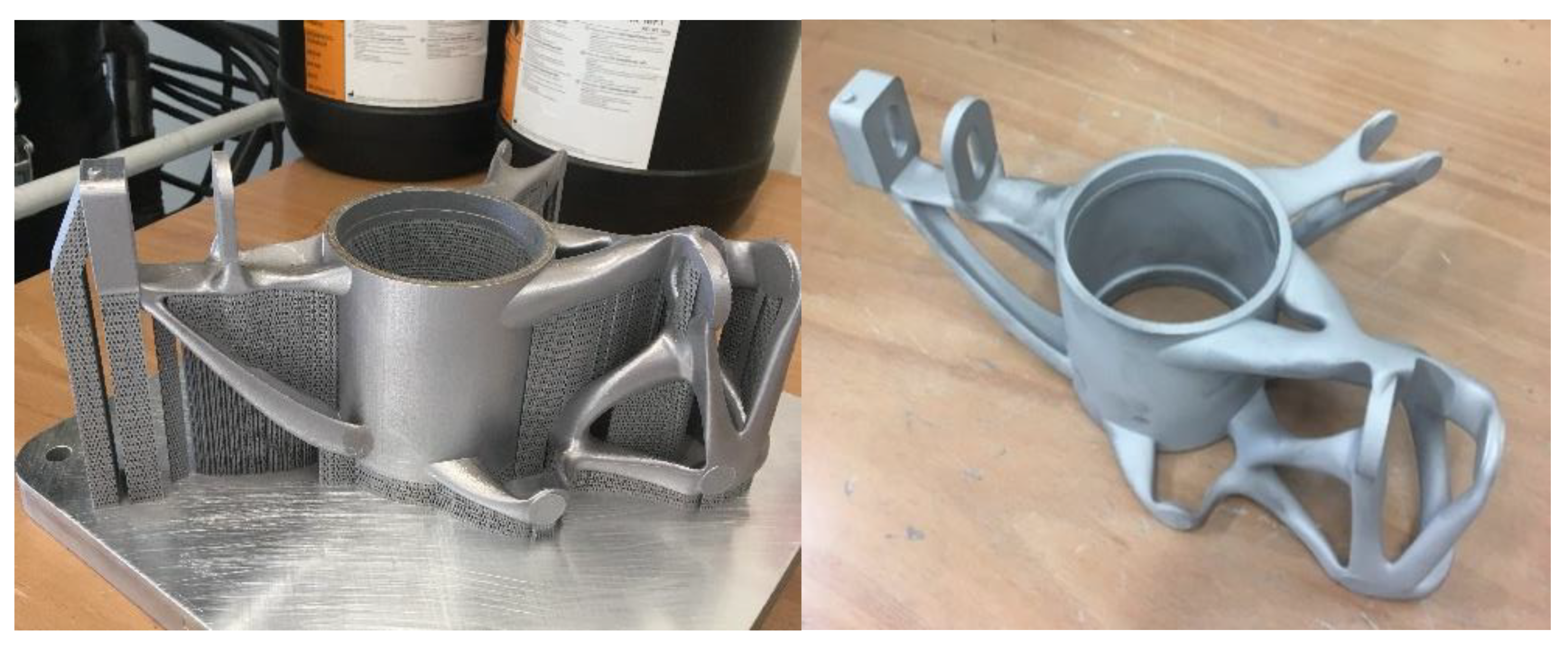
The manufacturing of the upright was performed by the SLM method—Selective Laser Melting. Since the material properties depend upon the quality of metal powder, it is important to choose an adequate producer of metal powder. For our upright, we used metal powder by the Renishaw company. The manufacturing took place on the printer SLM 280HL. The construction lasted about 15 h. During printing, we used a 400 W laser power, and the layer thickness was set to 25 μm. The metal powder was melted at 580 °C. The manufactured upright on the platform and with supports is shown in
Figure 12.
After manufacturing, a finishing process is required. This began with the removal of the upright from the machine and the subsequent cleaning of the untreated powder. This was followed by heat treatment, particularly annealing to 300 °C. Once the upright was removed from the platform, the supports were removed. At the end of the finishing process, tumbling for smoother structure should be performed.
The finishing process was followed by machining. All the surfaces were machined by a CNC machine. The main central holes were milled with tolerance H7; other holes were drilled according to ISO 2768-mK. Due to the SLM manufacturing inaccuracies, the holes do not have a precise circle shape but rather the shape of an ellipse, therefore each function hole must be drilled. The finished rear upright can be seen in
Figure 12.
3. Comparison of the Milled Upright and Topologically Optimized Upright
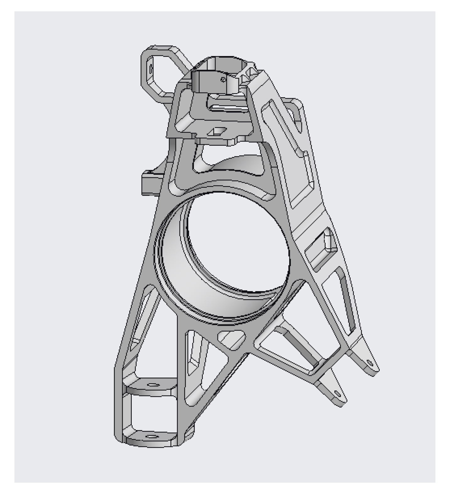
We had made two types of uprights. The first type of upright is manufactured by the conventional machining process like a milling (see
Figure 13). The second type of upright is created using the above-mentioned topology optimization. To compare the properties of the milled upright and the optimized upright, stress analyses were performed. The problem arises in the use of the material, because a high-strength aluminum alloy can be used for the milled upright, which cannot be used for a 3D printed upright due to its susceptibility to embrittlement. AlSi10Mg aluminum alloy had to be used for the 3D printed upright because it is the only one that has sufficient proven process parameters and good mechanical properties for 3D printed components [
34].
One of the important benefits of a 3D printed upright remains in its manufacture, which is quite complicated with the milled upright. Being a very complex model, most companies refuse to mill only one prototype part, while printing the topologically optimized upright was no problem, as 3D printing is becoming increasingly popular in companies. When produced by the conventional method of upright, the waste is over 90% of the material, which is also a major disadvantage of the milled upright. On the other hand, the cost of producing the milled upright is 350 € cheaper than the printed upright. The total price of the milled upright was calculated at 1500 €, by calculating the consumed material and the price of the CNC machining. The 3D printing of the printed upright was priced in the software QuantAM (Renishaw, Wotton-under-Edge, Great Britain) [
35] and subsequently the CNC machining of the functional surfaces and finishing processes was priced. The 3D printed upright was priced at 1850 €.
The weight reduction of the milled upright was performed by an iterative method of FEM analysis and the subsequent removal of material. A computer model was created and then FEM analysis was performed, which showed the maximum stress areas and the maximum deformation. The material was removed until the maximum stress began to approach the yield strength. The disadvantage of this method is that any kind of remove volume from the milled upright is at the expense of stiffness, while the topology-optimized upright offers possible developing for next season, in view of decreasing the weight and improving the stiffness.
In comparison the topology-optimized upright with the milled upright with the same aluminum alloy, AlSi10Mg, results of topologically optimized upright completely exceed results of milled upright. Not only is the topology-optimized upright 40% lighter, but it is also designed to withstand maximum loads with a safety factor greater than 1.8. The deformations are larger on the topology-optimized upright than on the milled upright, but the difference is not significant. The uprights are among the unsprung parts of the chassis, where each lightening of the material has a great influence on the driving properties. The summary of the comparison of milled upright and topologically optimized upright is shown in
Table 4.
4. Conclusions
Nowadays, topological optimization opens up new approaches to component design to reduce weight and increase stiffness. It is mainly used in the aviation and racing industries, into which the Formula Student rightfully falls. There were problems when creating the finished model that had to be solved. The aluminum alloy AlSi10Mg was used, which is produced in the form of a powder for 3D printing and cannot be equal in strength to the high-strength aluminum alloys used for uprights made by conventional methods; therefore, the upright had to be more reinforced and this resulted in an increased weight. On the other hand, heavy metal like maraging steel achieves a high strength yield, but its density is too high so that is not possible to reach a model under 1 kg with a factor of safety higher than 1.5.
Another problem occurred in the choice of the minimum element size for simulation. If the minimum element size was set to only 1 mm, the simulation could take days; therefore, a compromise has been established and the element size of 5 mm was selected with respect that the simulation will run in three load cases.
When performing the static structural analysis, the greatest stress was at the tip of the lower arm holder. The subsequent densification of the mesh has proven that the stress in tip is real and needs to be addressed. The model was exported to CAD software that no longer works with polyNURBS modelling, and the model was modified to reduce the peak stress. The problem was solved by increasing the radius and area around the stressed peak.
The model was subsequently checked by a static structural analysis to see if the radius adjustment addressed the issue of high stress.
The results of our first topologically optimized upright were satisfactory. The upright has reached 700 g with 0.28 mm of maximum deformation. This reduction in unsprung weight helps the vehicle to be faster and improves the dynamic control of the vehicle. However, there are still many improvements to this topologically optimized upright; therefore, subsequent development is possible, while the upright manufactured by conventional methods has reached its maximum.
Author Contributions
Conceptualization, M.H. and L.J.; methodology, M.H.; software, M.H.; validation, M.H. and L.J.; formal analysis, M.H.; investigation, M.H.; resources, M.H. and L.J.; data curation, L.J. and M.H.; writing—original draft preparation: M.H.; writing—review and editing, M.H., L.J., D.K. (David Krzikalla), D.K. (David Kaprinay) and D.S.; visualization, M.H.; supervision, M.H. and L.J.; project administration, M.H. and L.J.; funding acquisition, L.J. All authors have read and agreed to the published version of the manuscript.
Funding
The research was funded in association with project Innovative and additive manufacturing technology—new technological solutions for 3D printing of metals and composite materials, reg. no. CZ.02.1.01/0.0/0.0/17_049/0008407 financed by Structural Funds of the European Union and project.
Acknowledgments
This article has been completed in connection with project Innovative and additive manufacturing technology–new technological solutions for 3D printing of metals and composite materials, reg. no. CZ.02.1.01/0.0/0.0/17_049/0008407 financed by Structural Funds of European Union and project. This article has been elaborated in the research project Research Centre of Advanced Mechatronic Systems, reg. no. CZ.02.1.01/0.0/0.0/16_019/0000867 in the frame of the Operational Program Research, Development and Education.
Conflicts of Interest
The authors declare no conflict of interest.
References
- Formula Student Rules 2020, Version: 1.0, Formula Student Germany. Available online: https://www.formulastudent.de/fileadmin/user_upload/all/2020/rules/FS-Rules_2020_V1.0.pdf (accessed on 1 January 2020).
- Mesicek, J.; Richtar, M.; Petru, J.; Pagac, M.; Kutiova, K. Complex view to racing car upright design and manufacturing. Manuf. Technol. 2018, 18, 449–456. [Google Scholar] [CrossRef]
- Kumar, D.B.V.; Ruchitha, B.; Kumar, N.G.E. Design and analysis of upright for Formula vehicle. Int. J. Trend Sci. Res. Dev. 2019, 3, 1184–1189. [Google Scholar] [CrossRef]
- Maršálek, P.; Grycar, A.; Karásek, T.; Brzobohatý, T. Virtual prototyping of 3D printed cranial orthoses by finite element analysis. In Central European Symposium on Thermophysics 2019 (CEST); Aip Publishing: College Park, MD, USA, 2019. [Google Scholar]
- Čech, R.; Horyl, P.; Maršálek, P. Modelling of two-seat connection to the frame of rail wagon in terms of resistance at impact test. SC-JME 2016, 66, 101–106. [Google Scholar] [CrossRef]
- Mesicek, J.; Pagac, M.; Petru, J.; Novak, P.; Hajnys, J.; Kutiova, K. Topological optimization of the Formula Student bell crank. MM Sci. J. 2019, 3, 2964–2968. [Google Scholar] [CrossRef]
- Lipina, J.; Krys, V. Application of rapid prototyping technology in designing robots and peripheral devices. MM Sci. J. 2016, 1, 856–861. [Google Scholar] [CrossRef]
- Marler, R.T.; Arora, J.S. Survey of multi-objective optimization methods for engineering. Struct. Multidisc. Optim. 2004, 26, 369–395. [Google Scholar] [CrossRef]
- Cazacu, R.; Grama, L. Overview of structural topology optimization methods for plane and solid structures. Fasc. Manag. Technol. Eng. 2014, 23, 1583–1591. [Google Scholar]
- Vaverka, O.; Koutny, D.; Palousek, D. Topologically optimized axle carrier for Formula Student produced by selective laser melting. Rapid Prototyp. J. 2019, 25, 1545–1551. [Google Scholar] [CrossRef]
- Afkhami, S.; Dabiri, M.; Alavi, S.H.; Björk, T.; Salminen, A. Fatigue characteristics of steels manufactured by selective laser melting. Int. J. Fatigue 2019, 122, 72–83. [Google Scholar] [CrossRef]
- Spišák, E.; Gajdoš, I.; Slota, J. Optimization of FDM prototypes mechanical properties with path generation strategy. Appl. Mech. Mater. 2014, 474, 273–278. [Google Scholar] [CrossRef]
- Eschenauer, H.A.; Olhoff, N. Topology optimization of continuum structures: A review. Appl. Mech. Rev. 2001, 54, 331–390. [Google Scholar] [CrossRef]
- Bendsoe, M.P.; Sigmund, O. Topology Optimization: Theory, Methods and Applications; Springer: Berlin, Germany, 2003; ISBN 3-540-42992-1. [Google Scholar]
- Hajnyš, J.; Pagáč, M.; Kotera, O.; Petrů, J.; Scholz, S. Influence of basic process parameters on mechanical and internal properties of 316L steel in SLM process for Renishaw AM400. MM Sci. J. 2018, 1, 2790–2794. [Google Scholar] [CrossRef]
- Hajnyš, J.; Pagáč, M.; Zlámal, T.; Petrů, J.; Kousal, L. Stiffness of 316L stainless steel support structures proposed for the SLM process. MATEC Web Conf. 2018, 244. [Google Scholar] [CrossRef]
- Hajnys, J.; Pagáč, M.; Měsíček, J.; Petru, J.; Król, M. Influence of scanning strategy parameters on residual stress in the SLM process according to the Bridge Curvature Method for AISI 316L stainless steel. Materials 2020, 13, 1659. [Google Scholar] [CrossRef] [PubMed]
- Adams—The Multibody Dynamics Simulation Solution. Available online: https://www.mscsoftware.com/product/adams (accessed on 2 February 2020).
- Data Sheets—Additive Manufacturing, Powders for Additive Manufacturing. Available online: https://www.renishaw.com/en/data-sheets-additive-manufacturing--17862 (accessed on 16 August 2019).
- DMG MORI Online Shop, AM Powder. Available online: https://shop.dmgmori.com/b2b/en/DMQP/AM-Powder/c/AMPowder?filter=%3AsolrSorting&page=0 (accessed on 5 January 2020).
- Pagáč, M.; Hajnyš, J.; Petrů, J.; Zlámal, T. Coparision of hardness of surface 316L stainless steel made by additive technology and cold rolling. Mater. Sci. Forum 2018, 919, 84–91. [Google Scholar] [CrossRef]
- Xie, Y.M.; Steven, G.P. Evolutionary structural optimization for dynamic problems. Comput. Struct. 1996, 58, 1067–1073. [Google Scholar] [CrossRef]
- Huang, X.; Xie, Y.M. Convergent and mesh-independent solutions for the bi-directional evolutionary structural optimization method. Finite Elem. Anal. Des. 2007, 43, 1039–1049. [Google Scholar] [CrossRef]
- Li, Q.; Steven, G.P.; Querin, O.M.; Xie, Y.M. Shape and topology design for heat conduction by evolutionary structural optimization. Int. J. Heat Mass Transf. 1999, 42, 3361–3371. [Google Scholar] [CrossRef]
- Tanskanen, P. The evolutionary structural optimization method: Theoretical aspects. Comput. Method. Appl. Mech. Eng. 2002, 191, 5485–5498. [Google Scholar] [CrossRef]
- Rozvany, G.I.N. Aims, scope, methods, history and unified terminology of computer-aided topology optimization in structural mechanics. Struct. Multidisc. Optim. 2001, 21, 90–108. [Google Scholar] [CrossRef]
- Solidthinking, Inc. Altair Inspire: Generate Structurally Efficient Concepts Quickly and Easily. Available online: https://solidthinking.com/product/inspire/ (accessed on 16 March 2020).
- Bendsoe, M.P. Optimal shape design as a material distribution problem. Struct. Optim. 1989, 1, 193–202. [Google Scholar] [CrossRef]
- Schindlerová, V.; Šajdlerová, I.; Mohyla, P. Optimization of metallurgical processes using dynamic simulation. Metal 2016, 1, 2013–2018. [Google Scholar]
- Novák, M.; Náprstková, N.; Józwik, J. Analysis of the surface profile and its material share during the grinding inconel 718 alloy. Adv. Sci. Technol. Res. J. 2015, 9, 41–48. [Google Scholar] [CrossRef]
- Inventor-Professional-Grade 3D CAD Software for Product Design and Engineering. Available online: https://www.autodesk.com/products/inventor/overview (accessed on 25 January 2020).
- Václav, Š.; Sivtsev, N.S.; Senderská, K. Investigation of stress-strain state of a workpiece at gauge burnishing of its holes. Adv. Sci. Technol. Res. J. 2017, 11, 211–222. [Google Scholar] [CrossRef]
- Materialise Magics—Product Information. Available online: https://www.materialise.com/en/software/magics/product-information (accessed on 23 March 2020).
- Nasa Becomes First Customer of HRL High Strength Aluminum 3D Printing Powder. Available online: https://3dprintingindustry.com/news/nasa-becomes-first-customer-of-hrl-high-strength-aluminum-3d-printing-powder-163530/ (accessed on 17 October 2019).
- QuantAM Build Preparation Software. Available online: https://www.renishaw.com/en/quantam-build-preparation-software--35455 (accessed on 5 March 2019).
© 2020 by the authors. Licensee MDPI, Basel, Switzerland. This article is an open access article distributed under the terms and conditions of the Creative Commons Attribution (CC BY) license (http://creativecommons.org/licenses/by/4.0/).


